EP3581918B1 - Spektrometrische sonde zur probenentnahme von schüttgut und automatischer probennehmer zur probenentnahme mit der sonde - Google Patents
Spektrometrische sonde zur probenentnahme von schüttgut und automatischer probennehmer zur probenentnahme mit der sonde Download PDFInfo
- Publication number
- EP3581918B1 EP3581918B1 EP18750984.9A EP18750984A EP3581918B1 EP 3581918 B1 EP3581918 B1 EP 3581918B1 EP 18750984 A EP18750984 A EP 18750984A EP 3581918 B1 EP3581918 B1 EP 3581918B1
- Authority
- EP
- European Patent Office
- Prior art keywords
- sampling
- probe
- spectrometric
- bulk material
- reader
- Prior art date
- Legal status (The legal status is an assumption and is not a legal conclusion. Google has not performed a legal analysis and makes no representation as to the accuracy of the status listed.)
- Active
Links
Images

Classifications
-
- G—PHYSICS
- G01—MEASURING; TESTING
- G01N—INVESTIGATING OR ANALYSING MATERIALS BY DETERMINING THEIR CHEMICAL OR PHYSICAL PROPERTIES
- G01N21/00—Investigating or analysing materials by the use of optical means, i.e. using sub-millimetre waves, infrared, visible or ultraviolet light
- G01N21/17—Systems in which incident light is modified in accordance with the properties of the material investigated
- G01N21/25—Colour; Spectral properties, i.e. comparison of effect of material on the light at two or more different wavelengths or wavelength bands
- G01N21/27—Colour; Spectral properties, i.e. comparison of effect of material on the light at two or more different wavelengths or wavelength bands using photo-electric detection ; circuits for computing concentration
-
- G—PHYSICS
- G01—MEASURING; TESTING
- G01N—INVESTIGATING OR ANALYSING MATERIALS BY DETERMINING THEIR CHEMICAL OR PHYSICAL PROPERTIES
- G01N21/00—Investigating or analysing materials by the use of optical means, i.e. using sub-millimetre waves, infrared, visible or ultraviolet light
- G01N21/17—Systems in which incident light is modified in accordance with the properties of the material investigated
- G01N21/25—Colour; Spectral properties, i.e. comparison of effect of material on the light at two or more different wavelengths or wavelength bands
- G01N21/31—Investigating relative effect of material at wavelengths characteristic of specific elements or molecules, e.g. atomic absorption spectrometry
- G01N21/35—Investigating relative effect of material at wavelengths characteristic of specific elements or molecules, e.g. atomic absorption spectrometry using infrared light
- G01N21/3563—Investigating relative effect of material at wavelengths characteristic of specific elements or molecules, e.g. atomic absorption spectrometry using infrared light for analysing solids; Preparation of samples therefor
-
- G—PHYSICS
- G01—MEASURING; TESTING
- G01N—INVESTIGATING OR ANALYSING MATERIALS BY DETERMINING THEIR CHEMICAL OR PHYSICAL PROPERTIES
- G01N21/00—Investigating or analysing materials by the use of optical means, i.e. using sub-millimetre waves, infrared, visible or ultraviolet light
- G01N21/84—Systems specially adapted for particular applications
- G01N21/85—Investigating moving fluids or granular solids
- G01N21/8507—Probe photometers, i.e. with optical measuring part dipped into fluid sample
-
- G—PHYSICS
- G01—MEASURING; TESTING
- G01N—INVESTIGATING OR ANALYSING MATERIALS BY DETERMINING THEIR CHEMICAL OR PHYSICAL PROPERTIES
- G01N27/00—Investigating or analysing materials by the use of electric, electrochemical, or magnetic means
- G01N27/02—Investigating or analysing materials by the use of electric, electrochemical, or magnetic means by investigating impedance
- G01N27/22—Investigating or analysing materials by the use of electric, electrochemical, or magnetic means by investigating impedance by investigating capacitance
-
- G—PHYSICS
- G01—MEASURING; TESTING
- G01N—INVESTIGATING OR ANALYSING MATERIALS BY DETERMINING THEIR CHEMICAL OR PHYSICAL PROPERTIES
- G01N33/00—Investigating or analysing materials by specific methods not covered by groups G01N1/00 - G01N31/00
- G01N33/02—Food
-
- G—PHYSICS
- G01—MEASURING; TESTING
- G01N—INVESTIGATING OR ANALYSING MATERIALS BY DETERMINING THEIR CHEMICAL OR PHYSICAL PROPERTIES
- G01N21/00—Investigating or analysing materials by the use of optical means, i.e. using sub-millimetre waves, infrared, visible or ultraviolet light
- G01N21/84—Systems specially adapted for particular applications
- G01N21/85—Investigating moving fluids or granular solids
- G01N2021/8592—Grain or other flowing solid samples
-
- G—PHYSICS
- G01—MEASURING; TESTING
- G01N—INVESTIGATING OR ANALYSING MATERIALS BY DETERMINING THEIR CHEMICAL OR PHYSICAL PROPERTIES
- G01N21/00—Investigating or analysing materials by the use of optical means, i.e. using sub-millimetre waves, infrared, visible or ultraviolet light
- G01N21/17—Systems in which incident light is modified in accordance with the properties of the material investigated
- G01N21/25—Colour; Spectral properties, i.e. comparison of effect of material on the light at two or more different wavelengths or wavelength bands
- G01N21/31—Investigating relative effect of material at wavelengths characteristic of specific elements or molecules, e.g. atomic absorption spectrometry
- G01N21/35—Investigating relative effect of material at wavelengths characteristic of specific elements or molecules, e.g. atomic absorption spectrometry using infrared light
- G01N21/359—Investigating relative effect of material at wavelengths characteristic of specific elements or molecules, e.g. atomic absorption spectrometry using infrared light using near infrared light
Definitions
- the present invention relates to the field of devices, means or arrangements used for the sampling of bulk material, such as post-harvest grains, and more particularly the invention relates to a spectrometric probe and an automatic sampler for directly sampling parameters of quality and composition of bulk materials in the same place in which they are stored, such as a silo, truck or transport wagon, without the need to take samples that has to be transferred to remote units for their examination and evaluation.
- the sampling of post-harvest bulk material is well known, and it is known that it is a fundamental practice to know the conditions of, for example, grains, prior to their commercialization.
- the methodology to be used will depend on the type of vehicle or means on which grains are transported to the silos or shipping ports. Among the methods, the following can be found: the sampling of grains supplied in sacks, probe sampling, sampling by emptying the sacks, sampling of grains supplied in bulk, sampling of the product in rest state, sampling of the product in movement, cone method, among so many others. In all cases, the moisture content measurement and the corresponding quality analyzes will be carried out on the final sample.
- an automatic sampler is used, which is a probe remotely commanded from a cabin, which is inserted several times and in different locations in the load of the truck, both in the chassis and in the trailer to carry out the sampling.
- a plurality of nozzles along the entire probe are automatically opened to allow the entry of the sample by gravity.
- samples are taken at the top, middle and bottom, the collected sample being sent to the receiver bed via a pneumatic arrangement well known in the art, which is separated by sections (Upper, Middle, Bottom and bottom nozzle).
- the trained operator performs a "commercial" visual quality control, which is a physical analysis in which the composition analysis of the samples is not performed.
- some samples shall be selected manually, making a set for their subsequent processing in a countertop spectrometer. From this last procedure, parameters of grains composition that were taken as samples are obtained, the results being compared with standard parameters to know if they are suitable for commercialization.
- probes for sampling and/or performing measurements in a bulk material are described in paten documents WO 2007/000166 A1 , WO 2016/059865 A1 , US 2007/224853 A1 and US 2012/086429 A1 .
- It is also another object of the present invention to provide a spectrometric probe for the sampling of bulk material comprising at least one sampling module mounted on a section of the probe and which is formed by a casing having at least one front wall that has a transparent inspection window, said casing also having a capacitive sensor that protrudes outside the casing to contact the mass of the bulk material to be sampled, and at least one optical sampling sensor being arranged inside said casing and directed according to a reading path towards said inspection window, the optical sampling sensor being operatively connected to a remote control panel.
- the invention consists of a new spectrometric probe and an automatic sampler for sampling bulk material, where the probe allows to obtain information on parameters of interest of the composition of the material, such as protein, moisture, fat and others, directly in large quantities, avoiding the transfer of samples that shall be examined to external places under the observation and analysis of trained and specialized personnel, thus optimizing operation times and reducing related costs.
- parameters of interest of the composition of the material such as protein, moisture, fat and others
- the probe of the present invention can operate with wavelengths that vary between visible and NIR, the range being used according to the needs and requirements of each user.
- the probe in order to carry out the "opening" of the nozzles or intakes (14'), the probe can internally be provided with a rotating "C"-shaped half-shaft that is driven by an external motor (not shown).
- an external motor not shown
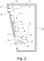
- the grains or bulk material enter allowing the taking of samples from the trailer of the truck or wagon for further analysis.
- the samples are transferred to an outbuilding or outer room (15) in which there is at least a trained and specialized personnel that performs the visual inspection of the samples and, if necessary, carries out the composition analysis as performed in conventional practice.
- the spectrometric probe is provided with the sampling module (16) which prevents the transfer of the grain samples to the outer room for carrying out the subsequent composition analysis thereof. That is to say, by means of the sampling module (16) according to the present invention, the obtaining of the different composition parameters of the grains can be carried out directly, significantly reducing times and related costs.
- the sampling module (16) can be fitted or mounted in the vicinity of the lower end (7) of the probe (2) and comprises a casing having a front wall (17) provided with a hole (18) and a transparent inspection window (19) that can be of quartz, sapphire or any other optical material that may be highly NIR (near infrared radiation) transmitter, a rear wall (20) and both side walls (21).
- said sampling module (16) may comprise a material selected from the group consisting of metallic, polymeric, ceramic materials or a combination thereof.
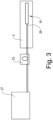
- said sampling module (16) is internally provided with at least one capacitive sensor (22) that can be arranged outwards and just beyond the hole (18) made on the front wall (17) of the module (16), or else right above, to come into contact with the bulk material, and which is connected to an electronic control unit (23).
- Said sampling module also has at least one optical sampling sensor (24) comprising a light source (25) defining a light beam along a lighting path directed towards said window (19), and a reader of light (26) reflected on the grain mass, wherein said reader (26) is directed according to said reading path and is connected to a remote control panel (27) by optical fiber (29).
- said light source (25) is mounted on a support (28) and can be a lamp or any type of related light source that is arranged adjacent to said transparent inspection window (19) provided on the front wall (17), while, said light reader (26) is a fiber optic reader which is also mounted on said support (28), at an angle with respect to the horizontal position of the light source (25) of between about 35 ° to 45.
- the beam of light emitted by the source (25) falls on the sample, producing a reflection of the beam at angles varying approximately between 35° and 45° and which is perceived and read by the reader (26) which is angularly arranged between said angles.
- the data read by the reader (26) are then sent to the control panel (27) who shall determine, based on different comparisons and data takings (mathematical model called calibration), the different composition parameters of the grains or sample.
- said control panel (27) can contain a NIR spectrometer, being that it can also be visible according to the wavelength used, protected and thermally stabilized. It is of the watertight type, protected and thermally stabilized, with industrial touch screen display, with integrated diode array, while said optical sampling sensor (24) is an optical sensor that covers the entire spectral bandwidth.
- the capacitive sensor (22) arranged at the opposite end to the transparent inspection window (19) has been illustrated, this is not a limitation for the invention, since said capacitive sensor can be arranged in the vicinity of the transparent window (19) without any inconvenience.
- the capacitive sensor (22) when the probe (2) is introduced into the grain, the capacitive sensor (22) is intended to send a signal informing that the sampling module (16) is already completely within the mass of the bulk material. Conversely, when the probe (2) is removed from the mass of bulk material, the capacitive sensor (22) shall detect that it is no longer in contact with the mass of material and this information shall be used by the software to, for example, interrupt the measurements and data collection.
- the sampling module (16) of the invention also has a linear actuator (9) comprising an actuator (10), for example a stepping motor that moves a piston (11) carrying at its end a black plate (12) and a white plate (13) intended to be positioned opposite the reading path of the fiber optic reader (26) to determine the limit points, of null reading, that is to say of null reflection by interposition of the black plate and of maximum reading, that is to say of maximum reflection by interposition of the white plate.
- an actuator (10) for example a stepping motor that moves a piston (11) carrying at its end a black plate (12) and a white plate (13) intended to be positioned opposite the reading path of the fiber optic reader (26) to determine the limit points, of null reading, that is to say of null reflection by interposition of the black plate and of maximum reading, that is to say of maximum reflection by interposition of the white plate.
- said black plate is made of a material selected from the group consisting of a matte black anodized aluminum laser cut and/or black eva rubber while said white plate is made of a material selected from the group consisting of a rectangular cut of Glaze Teflon material but it could also be ceramic or gold-plated metal plate 2 to 4 nm thick, Spectralon brand.
- the linear actuator is moved to extend the piston and place the black plate so that it stands in front of the reading path of the fiber optic reader.
- the software then establishes the zero point or zero reading point.
- the actuator is moved to place the white plate in the reading path of the fiber optic reader which shall read the reflection of the light emitted by the lamp that shall be reflected on the white plate that is made of a highly reflective material (Spectralon type).
- the reading of the light reflected on the white plate shall be taken by the software of the equipment as the maximum reflection point.
- the curves of reflections measured on the grain shall be drawn.
- This software can perform the system central command, acquisition, measurement, data recording and automatic communication with a computer cloud or with the plant system of the place.
- NIR near infrared radiation
- measurement through the use of Near Infrared Radiation is based on the ability of certain molecules to absorb energy in established bands. It is then an energetic phenomenon intimately related to the own and distinctive kinetics of the different molecules.
- This energy absorbed by a sample of bulk material results in a spectral image in the entire range of wavelengths in which the detector of the spectrometer is sensitive, being preferable to work between 900 nm and 2500 nm but understanding that the invention is not limited to said range, since it could be used without any inconvenience for any wavelength that varies between 400 nm and 3000 nm, being able to be Visible and/or NIR according to the needs of each user, and having thus other spectrometric ranges for the different applications that could occur in the future.
- the probe of the present invention can operate with wavelengths that vary between NIR or visible according to the needs of each user.
- This image is distinctive and unique, characteristic of the product analyzed.
- bands location of peaks
- the concentration of the different constituents is calculated.
- each molecular group Proteins, Fatty Acids, Fibers, Starch
- a truck, wagon or vehicle for transporting grain bulk material (30) enters the sampling street.
- the trained and specialized operator enters the Bill of Lading, activating the corresponding record in the corresponding Software.
- the Sampler operator starts the sampling operation.
- the probe (2) is introduced in the first location of the load of the truck.
- the capacitive sensor (22) detects when the mass of bulk material covers the quartz window (19).
- the spectral acquisition process is automatically triggered by a light beam generated by the source (25) and passing through the window (19).
- the system works like a "camera", obtaining complete spectra. This "scanning” process continues until the probe (2) reaches the bottom and the sampling nozzles (14) are opened.
- the software detects the opening pulse and stops the spectral acquisition. It averages the spectra taken in descent and delivers a partial result by sections. This allows the option of immediate and accurate re-samplings, saving notable times by repetition of operations once the sampling is completed.
- the pulse is detected by the Software restarting the spectral acquisition and continuing with the accumulation of complete punctual spectra.
- the capacitive sensor (22) is left to the "air" (free of bulk material)
- the indication of finishing the sampling arrives at the software. It averages and delivers a partial result of samplings.
- the process is repeated in each sampling. When finished, it is ordered to stop generating the total average of the truck, thus generating a complete grid for the cloud and system. The system is ready for the next truck/wagon that is triggered automatically with the first entry of the probe therein.
- partial quality determinations are achieved by probe lowering and by sampling (detection of specific foci and/or sampling repetition) without loss of time: precision of loads and fraud control.
- Visualization of average partial and final data moisture, protein, fat) in real time in industrial tactile panel. Classification of raw materials for the improvement of the quality of processed products.
- the sampling module that may or may not be fitted into the sampling probe, has been designed with the main objective of expanding and closing the grain quality control circle, generating reliable, traceable and historical information in pursuit of common welfare, managing to promote the sustainable development of regional agricultural production, improving and optimizing the nutritional composition of raw materials, with the efficient use of resources and through corrective actions.
Landscapes
- Physics & Mathematics (AREA)
- Chemical & Material Sciences (AREA)
- Health & Medical Sciences (AREA)
- Life Sciences & Earth Sciences (AREA)
- Immunology (AREA)
- Pathology (AREA)
- Analytical Chemistry (AREA)
- Biochemistry (AREA)
- General Health & Medical Sciences (AREA)
- General Physics & Mathematics (AREA)
- Engineering & Computer Science (AREA)
- Spectroscopy & Molecular Physics (AREA)
- Food Science & Technology (AREA)
- Medicinal Chemistry (AREA)
- Mathematical Physics (AREA)
- Theoretical Computer Science (AREA)
- Chemical Kinetics & Catalysis (AREA)
- Electrochemistry (AREA)
- Sampling And Sample Adjustment (AREA)
- Other Investigation Or Analysis Of Materials By Electrical Means (AREA)
- Investigating Or Analysing Materials By Optical Means (AREA)
Claims (8)
- Eine spektrometrische Sonde (2) zur Probenahme von Schüttgut, dadurch gekennzeichnet, dass sie Folgendes umfasst:- mindestens ein an einem Abschnitt der Sonde angebrachtes Probenahmemodul (16), das durch ein Gehäuse mit mindestens einer Vorderwand (17) mit einem transparenten Sichtfenster (19) gebildet ist,- wobei das Gehäuse ferner einen kapazitiven Sensor (22) hat, der aus dem Gehäuse herausragt, um die Masse des zu untersuchenden Schüttguts zu kontaktieren; und- wobei innerhalb des Gehäuses mindestens ein optischer Probenahmesensor (24) angeordnet ist, der gemäß einem Lesepfad zu dem Sichtfenster (19) hin gerichtet ist, wobei der optische Probenahmesensor (24) operativ mit einem Fernbedienfeld (27) verbunden ist; und- der optische Probenahmesensor (24) eine Lichtquelle (25), die einen Lichtstrahl entlang eines zum Fenster (19) hin gerichteten Beleuchtungspfads definiert, und einen Leser (26) von an der Masse des Schüttguts reflektiertem Licht umfasst, wobei der Leser (26) gemäß dem Lesepfad gerichtet ist, wobei der Leser (26) durch optische Faser mit dem Bedienfeld (27) verbunden ist; und- das Probenahmemodul (16) ferner einen linearen Aktor (9) hat, der einen Aktor (10) umfasst, der mit einem Kolben (11) verbunden ist, der an seinem Ende eine schwarze Platte (12) und eine weiße Platte (13) trägt, die zwischen temporären Betriebspositionen vor dem Lesepfad des Lesers (26) liegen.
- Eine spektrometrische Sonde nach Anspruch 1, dadurch gekennzeichnet, dass der reflektierte Lichtleser (26) ein faseroptischer Leser ist.
- Eine spektrometrische Sonde nach den vorhergehenden Ansprüchen, dadurch gekennzeichnet, dass die Lichtquelle (25) und der faseroptische Leser (26) auf einem Träger (28) montiert sind und winkelversetzt zwischen etwa 35° bis 45° angeordnet sind.
- Eine spektrometrische Sonde nach Anspruch 1, dadurch gekennzeichnet, dass das Bedienfeld (27) ein Spektrometer ist, während der optische Sensor (24) ein optischer Sensor ist, der alle spektrometrischen Bänder abdeckt.
- Eine spektrometrische Sonde nach Anspruch 1, dadurch gekennzeichnet, dass der kapazitive Sensor (22) operativ mit einer elektronischen Steuereinheit (23) verbunden ist.
- Eine spektrometrische Sonde nach Anspruch 1, dadurch gekennzeichnet, dass das Probenahmemodul (16) die Vorderwand (17), eine Rückwand (20) und jeweilige Seitenwände (21) umfasst, die aus einem Material hergestellt sein können, das ausgewählt ist aus der Gruppe bestehend aus metallischen, polymeren, keramischen Materialien oder einer Kombination davon.
- Eine spektrometrische Sonde nach Anspruch 1, dadurch gekennzeichnet, dass die schwarze Platte (12) aus einem Material hergestellt ist, das aus der Gruppe ausgewählt ist, die aus einem mattschwarz eloxierten Aluminium-Laserschnitt und/oder schwarzem Eva-Gummi besteht, während die weiße Platte (13) aus einem Material hergestellt ist, das aus der Gruppe ausgewählt ist, die aus einem rechteckigen Schnitt eines Spektralon-Materials mit einer Dicke von 2 bis 4 nm besteht.
- Ein automatischer Probenehmer zum Probennehmen von Schüttgut unter Verwendung der spektrometrischen Sonde (2) nach einem der vorhergehenden Ansprüche, dadurch gekennzeichnet, dass er Folgendes umfasst:- die Sonde (2), die von einem Gelenkarm (3) angetrieben wird;- wobei der Arm (3) eine Vielzahl von Düsen (14) hat, die sich in mindestens einem oberen, mittleren und unteren Abschnitt der Sonde (2) zum Entnehmen von Materialproben befinden;- wobei der Gelenkarm (3) mit einem seiner Enden an einer Säule (4) befestigt ist, die eine vertikale Stütze (5) hat;- wobei der Gelenkarm (3) von einem Zylinder (6) angetrieben wird, der aus der Gruppe ausgewählt ist, die aus einem Pneumatikzylinder, einem elektropneumatischen Zylinder und einem Hydraulikzylinder besteht, wobei der Zylinder ein Ende, das an der Basis der vertikalen Stütze (5) befestigt ist, und ein Ende gegenüber dem ersten hat, das an dem Gelenkarm (3) befestigt ist; und- wobei der automatische Probenehmer ferner eine Steuereinheit (23) umfasst, die wirksam mit dem kapazitiven Sensor (22) der spektrometrischen Sonde (2) verbunden ist, so dass, wenn der kapazitive Sensor (22) erfasst, wenn die Masse des Schüttguts das transparente Sichtfenster (19) der spektrometrischen Sonde (2) bedeckt, der Probenahmeprozess des Schüttguts automatisch ausgelöst wird.
Applications Claiming Priority (2)
| Application Number | Priority Date | Filing Date | Title |
|---|---|---|---|
| ARP170100339A AR107595A1 (es) | 2017-02-10 | 2017-02-10 | Sonda espectrométrica para muestreo de material a granel y calador automático de muestreo que incorpora la sonda |
| PCT/ES2018/070047 WO2018146352A1 (es) | 2017-02-10 | 2018-01-22 | Sonda espectométrica para muestreo de material a granel y calador automático de muestreo que incorpora la sonda |
Publications (4)
| Publication Number | Publication Date |
|---|---|
| EP3581918A1 EP3581918A1 (de) | 2019-12-18 |
| EP3581918A4 EP3581918A4 (de) | 2021-01-06 |
| EP3581918C0 EP3581918C0 (de) | 2025-03-12 |
| EP3581918B1 true EP3581918B1 (de) | 2025-03-12 |
Family
ID=62596967
Family Applications (1)
| Application Number | Title | Priority Date | Filing Date |
|---|---|---|---|
| EP18750984.9A Active EP3581918B1 (de) | 2017-02-10 | 2018-01-22 | Spektrometrische sonde zur probenentnahme von schüttgut und automatischer probennehmer zur probenentnahme mit der sonde |
Country Status (12)
| Country | Link |
|---|---|
| US (1) | US10816457B2 (de) |
| EP (1) | EP3581918B1 (de) |
| CN (1) | CN110462375A (de) |
| AR (1) | AR107595A1 (de) |
| AU (1) | AU2018218356B2 (de) |
| BR (1) | BR112019016607B1 (de) |
| ES (1) | ES3032137T3 (de) |
| PL (1) | PL3581918T3 (de) |
| RU (1) | RU2751572C2 (de) |
| UA (1) | UA125591C2 (de) |
| UY (1) | UY37579A (de) |
| WO (1) | WO2018146352A1 (de) |
Families Citing this family (6)
| Publication number | Priority date | Publication date | Assignee | Title |
|---|---|---|---|---|
| ES3010437T3 (en) * | 2018-09-18 | 2025-04-03 | Chrysalabs Inc | Optical probe and method for in situ soil analysis |
| CA3121099C (en) | 2020-02-26 | 2022-01-04 | 9371-0184 Quebec Inc. | Optical probe and method for real-time and in-situ measurements of soil properties |
| CA3211093A1 (en) * | 2021-04-13 | 2022-10-20 | The Gsi Group Llc | Autonomous grain probe |
| CN114166555B (zh) * | 2021-11-30 | 2025-08-15 | 浙江海洋大学 | 一种海底岩石层勘测用粘式碎石取样结构 |
| JP2023137889A (ja) * | 2022-03-18 | 2023-09-29 | 株式会社トプコン | 穀物成分センサ及び穀物成分分析装置 |
| CN115791643A (zh) * | 2022-11-30 | 2023-03-14 | 山东钢铁股份有限公司 | 一种铁前原料场铁矿粉在线料种辨识装置 |
Family Cites Families (19)
| Publication number | Priority date | Publication date | Assignee | Title |
|---|---|---|---|---|
| US3789671A (en) * | 1971-10-29 | 1974-02-05 | H Larson | Particulate material sampling device |
| US4037476A (en) | 1976-06-21 | 1977-07-26 | Mccrabb James | Grain sampling probe |
| FR2551868B1 (fr) * | 1983-08-19 | 1986-03-21 | Serval Sa | Procede et dispositif d'echantillonnage automatique de matieres en vrac contenues dans des vehicules de transport |
| SU1634191A1 (ru) * | 1989-07-01 | 1991-03-15 | Днепропетровский государственный университет им.300-летия воссоединения Украины с Россией | Способ отбора опаковой формы кукурузы |
| SE468334B (sv) * | 1991-04-23 | 1992-12-14 | Peter Perten | Saett och anordning foer infraroedanalys, speciellt avseende livsmedel |
| DE19714115C2 (de) * | 1997-04-05 | 1999-12-23 | Bran & Luebbe | Vorrichtung zur optischen Bestimmung von Inhaltsstoffen eines rieselfähigen Gutes |
| US6836325B2 (en) * | 1999-07-16 | 2004-12-28 | Textron Systems Corporation | Optical probes and methods for spectral analysis |
| AU2001240121B2 (en) * | 2000-03-10 | 2005-06-23 | Textron Systems Corporation | Optical probes and methods for spectral analysis |
| DE10348040A1 (de) * | 2003-10-15 | 2005-05-19 | Deere & Company, Moline | Messeinrichtung |
| DE102004020350A1 (de) | 2004-04-24 | 2005-11-10 | Sentronic GmbH Gesellschaft für optische Meßsysteme | Vorrichtung zur optischen Analyse von Propen |
| US8530844B2 (en) * | 2005-06-27 | 2013-09-10 | Sfk Technology A/S | Recording of position-specific wavelength absorption spectra |
| DE102006013341B3 (de) | 2006-03-23 | 2007-10-18 | J & M Analytische Mess- Und Regeltechnik Gmbh | Vorrichtung und Verfahren zur Analyse, insbesondere fotometrischen oder spektralfotometrischen Analyse |
| US8603772B2 (en) | 2007-07-28 | 2013-12-10 | Bug Lab LLC | Particle sensor with wide linear range |
| US9285501B2 (en) * | 2008-11-04 | 2016-03-15 | Veris Technologies, Inc. | Multiple sensor system and method for mapping soil in three dimensions |
| JP2013515248A (ja) * | 2009-12-22 | 2013-05-02 | ビューラー・アクチエンゲゼルシャフト | 揺動可能な生成物を測定するための装置及び方法 |
| US8542363B2 (en) * | 2010-12-22 | 2013-09-24 | Endress + Hauser Conducta Inc. | Self-aligning light source and detector assembly for absorbance measurement |
| US9523652B2 (en) * | 2010-10-08 | 2016-12-20 | Poet Research, Inc. | Method and apparatus for measuring moisture content |
| JP5973521B2 (ja) * | 2014-10-15 | 2016-08-23 | 株式会社クボタ | 光学式穀粒評価装置 |
| WO2017223435A1 (en) * | 2016-06-23 | 2017-12-28 | The Taxas A&M University System | Vis-nir equipped soil penetrometer |
-
2017
- 2017-02-10 AR ARP170100339A patent/AR107595A1/es active IP Right Grant
-
2018
- 2018-01-22 CN CN201880010850.6A patent/CN110462375A/zh active Pending
- 2018-01-22 UY UY0001037579A patent/UY37579A/es active IP Right Grant
- 2018-01-22 US US16/308,791 patent/US10816457B2/en active Active
- 2018-01-22 WO PCT/ES2018/070047 patent/WO2018146352A1/es not_active Ceased
- 2018-01-22 UA UAA201909861A patent/UA125591C2/uk unknown
- 2018-01-22 ES ES18750984T patent/ES3032137T3/es active Active
- 2018-01-22 EP EP18750984.9A patent/EP3581918B1/de active Active
- 2018-01-22 RU RU2019128000A patent/RU2751572C2/ru active
- 2018-01-22 BR BR112019016607-6A patent/BR112019016607B1/pt active IP Right Grant
- 2018-01-22 AU AU2018218356A patent/AU2018218356B2/en active Active
- 2018-01-22 PL PL18750984.9T patent/PL3581918T3/pl unknown
Also Published As
| Publication number | Publication date |
|---|---|
| US20190187046A1 (en) | 2019-06-20 |
| EP3581918A1 (de) | 2019-12-18 |
| PL3581918T3 (pl) | 2025-06-09 |
| US10816457B2 (en) | 2020-10-27 |
| UA125591C2 (uk) | 2022-04-27 |
| RU2019128000A (ru) | 2021-03-10 |
| BR112019016607A2 (pt) | 2020-03-31 |
| AU2018218356B2 (en) | 2021-07-29 |
| RU2751572C2 (ru) | 2021-07-15 |
| EP3581918C0 (de) | 2025-03-12 |
| UY37579A (es) | 2018-08-31 |
| EP3581918A4 (de) | 2021-01-06 |
| BR112019016607B1 (pt) | 2023-12-19 |
| CN110462375A (zh) | 2019-11-15 |
| WO2018146352A1 (es) | 2018-08-16 |
| AR107595A1 (es) | 2018-05-16 |
| RU2019128000A3 (de) | 2021-05-28 |
| ES3032137T3 (en) | 2025-07-15 |
| AU2018218356A1 (en) | 2019-09-26 |
Similar Documents
| Publication | Publication Date | Title |
|---|---|---|
| EP3581918B1 (de) | Spektrometrische sonde zur probenentnahme von schüttgut und automatischer probennehmer zur probenentnahme mit der sonde | |
| RU2383881C2 (ru) | Спектрометрическая измерительная головка для уборочных и других сельскохозяйственных машин | |
| EP1740928B1 (de) | Verfahren zur rekalibrierung eines spektrometrischen messkopfes | |
| US6483583B1 (en) | Near infrared spectrometry for real time analysis of substances | |
| RU2492453C2 (ru) | Способ и устройство для анализа и разделения зерна | |
| DE102018103509B3 (de) | Mobiles Inhaltsstoffanalysesystem sowie Verfahren zur probenrichtigen Messung und Nutzerführung mit diesem | |
| CA2066722A1 (en) | Soil test apparatus | |
| WO1999058959A1 (en) | Near infrared spectrometry for real time analysis of substances | |
| CA2317725C (en) | Sampling apparatus | |
| CN119715414A (zh) | 一种基于多模态数据融合的种子质量评估系统及装置 | |
| DE102004021448B4 (de) | Spektrometrischer Reflexionsmesskopf und Verfahren zu dessen interner Rekalibrierung | |
| US11982616B2 (en) | Spectrally resolved imaging for agricultural product assessment | |
| US7847947B2 (en) | Spectroscopic lance for bulk sampling | |
| EP4550233A1 (de) | Automatisierungssystem zur aufnahme von erntegut | |
| US12007741B2 (en) | Automation system for receiving crops | |
| KR20070045636A (ko) | 근적외선 분광분석 기법을 이용한 비파괴 계란신선도측정시스템 및 그 방법 | |
| AU2006264210B2 (en) | Spectroscopic lance for bulk sampling | |
| US20080231853A1 (en) | Qualitative Analysis System and Method for Agricultural Products in Harvesting Equipment | |
| Adame-Siles et al. | Assessing the potential of two customized fiber-optic probes for on-site analysis of bulk feed grains | |
| Beghi et al. | Grape and juice handling: Assessing the use of visible and near infrared spectroscopy to rapidly evaluate the health status of grapes entering wineries | |
| CN121141683A (zh) | 一种塑料瓶检测装置及方法 |
Legal Events
| Date | Code | Title | Description |
|---|---|---|---|
| STAA | Information on the status of an ep patent application or granted ep patent |
Free format text: STATUS: THE INTERNATIONAL PUBLICATION HAS BEEN MADE |
|
| PUAI | Public reference made under article 153(3) epc to a published international application that has entered the european phase |
Free format text: ORIGINAL CODE: 0009012 |
|
| STAA | Information on the status of an ep patent application or granted ep patent |
Free format text: STATUS: REQUEST FOR EXAMINATION WAS MADE |
|
| 17P | Request for examination filed |
Effective date: 20190910 |
|
| AK | Designated contracting states |
Kind code of ref document: A1 Designated state(s): AL AT BE BG CH CY CZ DE DK EE ES FI FR GB GR HR HU IE IS IT LI LT LU LV MC MK MT NL NO PL PT RO RS SE SI SK SM TR |
|
| AX | Request for extension of the european patent |
Extension state: BA ME |
|
| DAV | Request for validation of the european patent (deleted) | ||
| DAX | Request for extension of the european patent (deleted) | ||
| A4 | Supplementary search report drawn up and despatched |
Effective date: 20201207 |
|
| RIC1 | Information provided on ipc code assigned before grant |
Ipc: G01N 21/3563 20140101ALI20201201BHEP Ipc: G01N 21/359 20140101ALI20201201BHEP Ipc: G01N 27/22 20060101ALI20201201BHEP Ipc: G01N 21/27 20060101AFI20201201BHEP Ipc: G01N 33/02 20060101ALI20201201BHEP Ipc: G01N 21/85 20060101ALI20201201BHEP |
|
| STAA | Information on the status of an ep patent application or granted ep patent |
Free format text: STATUS: EXAMINATION IS IN PROGRESS |
|
| 17Q | First examination report despatched |
Effective date: 20211110 |
|
| REG | Reference to a national code |
Ref legal event code: R079 Ipc: G01N0021356300 Ref country code: DE Ref legal event code: R079 Ref document number: 602018080048 Country of ref document: DE Free format text: PREVIOUS MAIN CLASS: G01N0021270000 Ipc: G01N0021356300 |
|
| GRAP | Despatch of communication of intention to grant a patent |
Free format text: ORIGINAL CODE: EPIDOSNIGR1 |
|
| STAA | Information on the status of an ep patent application or granted ep patent |
Free format text: STATUS: GRANT OF PATENT IS INTENDED |
|
| RIC1 | Information provided on ipc code assigned before grant |
Ipc: G01N 21/359 20140101ALI20240324BHEP Ipc: G01N 33/02 20060101ALI20240324BHEP Ipc: G01N 27/22 20060101ALI20240324BHEP Ipc: G01N 21/85 20060101ALI20240324BHEP Ipc: G01N 21/3563 20140101ALI20240324BHEP Ipc: G01N 21/27 20060101AFI20240324BHEP |
|
| INTG | Intention to grant announced |
Effective date: 20240418 |
|
| RIC1 | Information provided on ipc code assigned before grant |
Ipc: G01N 21/359 20140101ALN20240408BHEP Ipc: G01N 33/02 20060101ALI20240408BHEP Ipc: G01N 27/22 20060101ALI20240408BHEP Ipc: G01N 21/85 20060101ALI20240408BHEP Ipc: G01N 21/3563 20140101AFI20240408BHEP |
|
| GRAJ | Information related to disapproval of communication of intention to grant by the applicant or resumption of examination proceedings by the epo deleted |
Free format text: ORIGINAL CODE: EPIDOSDIGR1 |
|
| STAA | Information on the status of an ep patent application or granted ep patent |
Free format text: STATUS: EXAMINATION IS IN PROGRESS |
|
| GRAP | Despatch of communication of intention to grant a patent |
Free format text: ORIGINAL CODE: EPIDOSNIGR1 |
|
| INTC | Intention to grant announced (deleted) | ||
| STAA | Information on the status of an ep patent application or granted ep patent |
Free format text: STATUS: GRANT OF PATENT IS INTENDED |
|
| RIC1 | Information provided on ipc code assigned before grant |
Ipc: G01N 21/359 20140101ALN20240919BHEP Ipc: G01N 33/02 20060101ALI20240919BHEP Ipc: G01N 27/22 20060101ALI20240919BHEP Ipc: G01N 21/85 20060101ALI20240919BHEP Ipc: G01N 21/3563 20140101AFI20240919BHEP |
|
| INTG | Intention to grant announced |
Effective date: 20240926 |
|
| GRAS | Grant fee paid |
Free format text: ORIGINAL CODE: EPIDOSNIGR3 |
|
| GRAA | (expected) grant |
Free format text: ORIGINAL CODE: 0009210 |
|
| STAA | Information on the status of an ep patent application or granted ep patent |
Free format text: STATUS: THE PATENT HAS BEEN GRANTED |
|
| AK | Designated contracting states |
Kind code of ref document: B1 Designated state(s): AL AT BE BG CH CY CZ DE DK EE ES FI FR GB GR HR HU IE IS IT LI LT LU LV MC MK MT NL NO PL PT RO RS SE SI SK SM TR |
|
| REG | Reference to a national code |
Ref country code: GB Ref legal event code: FG4D |
|
| REG | Reference to a national code |
Ref country code: CH Ref legal event code: EP |
|
| REG | Reference to a national code |
Ref country code: IE Ref legal event code: FG4D |
|
| U01 | Request for unitary effect filed |
Effective date: 20250312 |
|
| U07 | Unitary effect registered |
Designated state(s): AT BE BG DE DK EE FI FR IT LT LU LV MT NL PT RO SE SI Effective date: 20250318 |
|
| REG | Reference to a national code |
Ref country code: DE Ref legal event code: R096 Ref document number: 602018080048 Country of ref document: DE |
|
| PG25 | Lapsed in a contracting state [announced via postgrant information from national office to epo] |
Ref country code: RS Free format text: LAPSE BECAUSE OF FAILURE TO SUBMIT A TRANSLATION OF THE DESCRIPTION OR TO PAY THE FEE WITHIN THE PRESCRIBED TIME-LIMIT Effective date: 20250612 |
|
| PG25 | Lapsed in a contracting state [announced via postgrant information from national office to epo] |
Ref country code: NO Free format text: LAPSE BECAUSE OF FAILURE TO SUBMIT A TRANSLATION OF THE DESCRIPTION OR TO PAY THE FEE WITHIN THE PRESCRIBED TIME-LIMIT Effective date: 20250612 |
|
| REG | Reference to a national code |
Ref country code: ES Ref legal event code: FG2A Ref document number: 3032137 Country of ref document: ES Kind code of ref document: T3 Effective date: 20250715 |
|
| PG25 | Lapsed in a contracting state [announced via postgrant information from national office to epo] |
Ref country code: HR Free format text: LAPSE BECAUSE OF FAILURE TO SUBMIT A TRANSLATION OF THE DESCRIPTION OR TO PAY THE FEE WITHIN THE PRESCRIBED TIME-LIMIT Effective date: 20250312 |
|
| PG25 | Lapsed in a contracting state [announced via postgrant information from national office to epo] |
Ref country code: GR Free format text: LAPSE BECAUSE OF FAILURE TO SUBMIT A TRANSLATION OF THE DESCRIPTION OR TO PAY THE FEE WITHIN THE PRESCRIBED TIME-LIMIT Effective date: 20250613 |
|
| PG25 | Lapsed in a contracting state [announced via postgrant information from national office to epo] |
Ref country code: SM Free format text: LAPSE BECAUSE OF FAILURE TO SUBMIT A TRANSLATION OF THE DESCRIPTION OR TO PAY THE FEE WITHIN THE PRESCRIBED TIME-LIMIT Effective date: 20250312 |
|
| PG25 | Lapsed in a contracting state [announced via postgrant information from national office to epo] |
Ref country code: CZ Free format text: LAPSE BECAUSE OF FAILURE TO SUBMIT A TRANSLATION OF THE DESCRIPTION OR TO PAY THE FEE WITHIN THE PRESCRIBED TIME-LIMIT Effective date: 20250312 |
|
| PG25 | Lapsed in a contracting state [announced via postgrant information from national office to epo] |
Ref country code: SK Free format text: LAPSE BECAUSE OF FAILURE TO SUBMIT A TRANSLATION OF THE DESCRIPTION OR TO PAY THE FEE WITHIN THE PRESCRIBED TIME-LIMIT Effective date: 20250312 |
|
| PG25 | Lapsed in a contracting state [announced via postgrant information from national office to epo] |
Ref country code: IS Free format text: LAPSE BECAUSE OF FAILURE TO SUBMIT A TRANSLATION OF THE DESCRIPTION OR TO PAY THE FEE WITHIN THE PRESCRIBED TIME-LIMIT Effective date: 20250712 |
|
| PLBE | No opposition filed within time limit |
Free format text: ORIGINAL CODE: 0009261 |
|
| STAA | Information on the status of an ep patent application or granted ep patent |
Free format text: STATUS: NO OPPOSITION FILED WITHIN TIME LIMIT |
|
| REG | Reference to a national code |
Ref country code: CH Ref legal event code: L10 Free format text: ST27 STATUS EVENT CODE: U-0-0-L10-L00 (AS PROVIDED BY THE NATIONAL OFFICE) Effective date: 20260121 |