EP3579348A1 - Kontakthülse für einen elektrischen steckverbinder - Google Patents
Kontakthülse für einen elektrischen steckverbinder Download PDFInfo
- Publication number
- EP3579348A1 EP3579348A1 EP19182255.0A EP19182255A EP3579348A1 EP 3579348 A1 EP3579348 A1 EP 3579348A1 EP 19182255 A EP19182255 A EP 19182255A EP 3579348 A1 EP3579348 A1 EP 3579348A1
- Authority
- EP
- European Patent Office
- Prior art keywords
- contact
- sleeve
- contact spring
- contact sleeve
- elevations
- Prior art date
- Legal status (The legal status is an assumption and is not a legal conclusion. Google has not performed a legal analysis and makes no representation as to the accuracy of the status listed.)
- Granted
Links
Images
Classifications
-
- H—ELECTRICITY
- H01—ELECTRIC ELEMENTS
- H01R—ELECTRICALLY-CONDUCTIVE CONNECTIONS; STRUCTURAL ASSOCIATIONS OF A PLURALITY OF MUTUALLY-INSULATED ELECTRICAL CONNECTING ELEMENTS; COUPLING DEVICES; CURRENT COLLECTORS
- H01R13/00—Details of coupling devices of the kinds covered by groups H01R12/70 or H01R24/00 - H01R33/00
- H01R13/02—Contact members
- H01R13/04—Pins or blades for co-operation with sockets
- H01R13/05—Resilient pins or blades
-
- H—ELECTRICITY
- H01—ELECTRIC ELEMENTS
- H01R—ELECTRICALLY-CONDUCTIVE CONNECTIONS; STRUCTURAL ASSOCIATIONS OF A PLURALITY OF MUTUALLY-INSULATED ELECTRICAL CONNECTING ELEMENTS; COUPLING DEVICES; CURRENT COLLECTORS
- H01R13/00—Details of coupling devices of the kinds covered by groups H01R12/70 or H01R24/00 - H01R33/00
- H01R13/02—Contact members
- H01R13/15—Pins, blades or sockets having separate spring member for producing or increasing contact pressure
- H01R13/187—Pins, blades or sockets having separate spring member for producing or increasing contact pressure with spring member in the socket
-
- H—ELECTRICITY
- H01—ELECTRIC ELEMENTS
- H01R—ELECTRICALLY-CONDUCTIVE CONNECTIONS; STRUCTURAL ASSOCIATIONS OF A PLURALITY OF MUTUALLY-INSULATED ELECTRICAL CONNECTING ELEMENTS; COUPLING DEVICES; CURRENT COLLECTORS
- H01R13/00—Details of coupling devices of the kinds covered by groups H01R12/70 or H01R24/00 - H01R33/00
- H01R13/02—Contact members
- H01R13/04—Pins or blades for co-operation with sockets
- H01R13/05—Resilient pins or blades
- H01R13/052—Resilient pins or blades co-operating with sockets having a circular transverse section
-
- H—ELECTRICITY
- H01—ELECTRIC ELEMENTS
- H01R—ELECTRICALLY-CONDUCTIVE CONNECTIONS; STRUCTURAL ASSOCIATIONS OF A PLURALITY OF MUTUALLY-INSULATED ELECTRICAL CONNECTING ELEMENTS; COUPLING DEVICES; CURRENT COLLECTORS
- H01R13/00—Details of coupling devices of the kinds covered by groups H01R12/70 or H01R24/00 - H01R33/00
- H01R13/02—Contact members
- H01R13/10—Sockets for co-operation with pins or blades
- H01R13/11—Resilient sockets
-
- H—ELECTRICITY
- H01—ELECTRIC ELEMENTS
- H01R—ELECTRICALLY-CONDUCTIVE CONNECTIONS; STRUCTURAL ASSOCIATIONS OF A PLURALITY OF MUTUALLY-INSULATED ELECTRICAL CONNECTING ELEMENTS; COUPLING DEVICES; CURRENT COLLECTORS
- H01R13/00—Details of coupling devices of the kinds covered by groups H01R12/70 or H01R24/00 - H01R33/00
- H01R13/02—Contact members
- H01R13/10—Sockets for co-operation with pins or blades
- H01R13/11—Resilient sockets
- H01R13/111—Resilient sockets co-operating with pins having a circular transverse section
-
- H—ELECTRICITY
- H01—ELECTRIC ELEMENTS
- H01R—ELECTRICALLY-CONDUCTIVE CONNECTIONS; STRUCTURAL ASSOCIATIONS OF A PLURALITY OF MUTUALLY-INSULATED ELECTRICAL CONNECTING ELEMENTS; COUPLING DEVICES; CURRENT COLLECTORS
- H01R13/00—Details of coupling devices of the kinds covered by groups H01R12/70 or H01R24/00 - H01R33/00
- H01R13/02—Contact members
- H01R13/15—Pins, blades or sockets having separate spring member for producing or increasing contact pressure
- H01R13/17—Pins, blades or sockets having separate spring member for producing or increasing contact pressure with spring member on the pin
-
- H—ELECTRICITY
- H01—ELECTRIC ELEMENTS
- H01R—ELECTRICALLY-CONDUCTIVE CONNECTIONS; STRUCTURAL ASSOCIATIONS OF A PLURALITY OF MUTUALLY-INSULATED ELECTRICAL CONNECTING ELEMENTS; COUPLING DEVICES; CURRENT COLLECTORS
- H01R13/00—Details of coupling devices of the kinds covered by groups H01R12/70 or H01R24/00 - H01R33/00
- H01R13/02—Contact members
- H01R13/22—Contacts for co-operating by abutting
- H01R13/24—Contacts for co-operating by abutting resilient; resiliently-mounted
- H01R13/2464—Contacts for co-operating by abutting resilient; resiliently-mounted characterized by the contact point
- H01R13/2492—Contacts for co-operating by abutting resilient; resiliently-mounted characterized by the contact point multiple contact points
-
- H—ELECTRICITY
- H01—ELECTRIC ELEMENTS
- H01R—ELECTRICALLY-CONDUCTIVE CONNECTIONS; STRUCTURAL ASSOCIATIONS OF A PLURALITY OF MUTUALLY-INSULATED ELECTRICAL CONNECTING ELEMENTS; COUPLING DEVICES; CURRENT COLLECTORS
- H01R24/00—Two-part coupling devices, or either of their cooperating parts, characterised by their overall structure
- H01R24/38—Two-part coupling devices, or either of their cooperating parts, characterised by their overall structure having concentrically or coaxially arranged contacts
- H01R24/40—Two-part coupling devices, or either of their cooperating parts, characterised by their overall structure having concentrically or coaxially arranged contacts specially adapted for high frequency
-
- H—ELECTRICITY
- H01—ELECTRIC ELEMENTS
- H01R—ELECTRICALLY-CONDUCTIVE CONNECTIONS; STRUCTURAL ASSOCIATIONS OF A PLURALITY OF MUTUALLY-INSULATED ELECTRICAL CONNECTING ELEMENTS; COUPLING DEVICES; CURRENT COLLECTORS
- H01R4/00—Electrically-conductive connections between two or more conductive members in direct contact, i.e. touching one another; Means for effecting or maintaining such contact; Electrically-conductive connections having two or more spaced connecting locations for conductors and using contact members penetrating insulation
- H01R4/28—Clamped connections, spring connections
- H01R4/48—Clamped connections, spring connections utilising a spring, clip, or other resilient member
Definitions
- the invention relates to a contact sleeve in the form of a hollow cylinder having a lateral surface and a central longitudinal axis for an electrical connector for making electrical contact with a mating connector, wherein the contact sleeve has on its lateral surface at least two pairs of contact spring blades, each pair arranged contact spring blades on the contact sleeve radially opposite wherein each contact spring blade having a radial projection which forms an electrical contact surface, wherein the elevations of a pair of opposing contact spring blades in the axial direction with respect to the contact sleeve at the same location are arranged such that their contact surfaces lie on a straight line perpendicular to the central longitudinal axis of the contact sleeve cuts, according to the preamble of claim 1.
- Connectors serve for the detachable connection of coaxial cables.
- Coaxial connectors such as coaxial cables, are coaxial to have the advantages of coaxial cables, namely low electromagnetic interference and radiation, as well as good electrical shielding and impedance equal to that of the coaxial cable connected, to reflect reflections at the interface between coaxial connectors and coaxial cables avoid.
- a coaxial cable, or coaxial cable for short is understood to mean a two-pole cable with a concentric construction, which has an inner conductor (also called a core) which is surrounded at a constant distance by a hollow-cylindrical outer conductor. The outer conductor shields the inner conductor from electromagnetic interference. In the space between the inner conductor and the outer conductor, an insulator or dielectric is arranged.
- Coaxial connectors are adapted to a predetermined characteristic impedance, for. B. of 50 ⁇ , to provide a reflection-free transmission of RF signals.
- the characteristic impedance of a coaxial connector depends inter alia on the ratio of the inner diameter of the outer conductor and the diameter of the inner conductor. An electrical connection of a coaxial cable to a coaxial connector therefore requires the respective inner diameter and outer diameter of the coaxial cable adapted coaxial connector.
- a bush-shaped stamped and bent part known as a contact socket for mating with a contact pin (contact pin) at a plug-side end.
- the contact socket has a cylindrical portion between two rings.
- This cylindrical portion is composed of a plurality of pairs of axially extending contact spring blades (beams).
- Each contact spring blade has an inwardly uplifting, spherical contact boss.
- the contact surfaces of an opposite pair of contact spring blades are arranged at the same distance from the plug-side end, wherein the contact surfaces on the contact spring blades are both arranged at a slightly greater distance from the plug-side end.
- the publication DE 20 2015 006 807 U1 relates to a contact blade part and a connector with contact blade part.
- the contact lamella part has a plurality of contact lamellae which run approximately parallel next to one another and each extend between a first connection body in the form of a carrier strip and a second connection body in the form of a carrier strip.
- the contact blades each extend web-like in a longitudinal direction L, while the connecting bodies formed integrally therewith extend approximately perpendicular thereto in the transverse direction.
- the transverse direction and the longitudinal direction span a lamellar plane which corresponds to the plane of the paper.
- the publication US 8 821 170 B1 shows an electrical contact socket with contact spring blades, each serving as electrical contact bending regions 2 have.
- the bending regions of adjacent contact spring blades are spaced apart in the axial direction.
- the publication US 5,667,413 A relates to an electrical contact socket with a contact cage, which has a plurality of contact spring blades.
- Each contact spring blade has a contact point, which is formed by a bent and thereby radially inwardly elevating part of the spring blade itself.
- the contact points of adjacent contact spring blades are spaced longitudinally relative to each other.
- the invention has for its object to improve a contact sleeve in terms of manual handling when plugging with a mating connector.
- the elevations rise radially inwardly and / or outwardly beyond the contact sleeve or beyond the jacket wall.
- a particularly good reduction of the insertion forces at the same time many electrical contact surfaces are achieved in that three pairs justifyfederlamellen are formed with respective projections on the contact sleeve, the elevations of each pair is offset relative to the elevations of all other pairs offset relative to the axial direction.
- contact spring lamellae are formed by circumferentially spaced apart arranged recesses in the contact sleeve or the jacket wall of the contact sleeve.
- contact spring blades with high spring forces for a good electrical contact with high contact force is achieved in that the contact spring blades are positively connected at both axial ends with the contact sleeve or with the jacket wall of the contact sleeve.
- a contact surface with low mechanical stresses during compression of the contact spring blades is achieved by the fact that the elevations are arcuate.
- a particularly advantageous gradation of the insertion force when inserting the contact sleeve into a mating connector is achieved in that the axial offset length between the elevations different or axially adjacent pairs of contact spring blades 0.2 mm, or a multiple thereof.
- a symmetrical arrangement of the contact spring lamellae on the contact sleeve is achieved in that n, with n ⁇ 2, pairs of contact louvers are formed on the contact sleeve, wherein the contact spring lamellae are circumferentially spaced by an angle of 360 (2 * n).
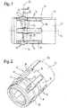
- a contact sleeve 10 is in the form of a hollow cylinder with casing wall 12 and a central longitudinal axis 14 is formed.
- a contact spring blade 18 By circumferentially uniformly spaced recesses 16 three pairs of contact spring blades 18 are formed, wherein each of the two contact spring blades 18 of a pair are arranged radially opposite to the jacket wall 12.
- Each contact spring blade 18 extends substantially in the axial direction Parallel to the central longitudinal axis 14.
- Respective axial ends of each contact spring blade 18 are positively formed with the jacket wall 12 of the contact sleeve 10.
- Each contact spring blade 18 has a radial elevation 20 is formed on the arcuate.
- the survey protrude radially outwardly beyond the jacket wall 12 of the contact sleeve 10 also.
- Each radial elevation forms at its highest point a contact surface 22 (indicated by dashed lines), which is designed for electrical and mechanical contacting of a mating connector.
- the contact surfaces 22 are rectangular and extend substantially perpendicular to the central longitudinal axis 14.
- the elevations of a pair of radially opposite contact spring blade 18 are located on a straight line 24 which intersects the central longitudinal axis 14 at a right angle.
- the elevations 20 or contact surfaces 22 of different pairs of contact spring blades 18 are spaced from one another in the axial direction with respect to the contact sleeve 10 by a predetermined axial offset length 26.
- a predetermined axial offset length 26 In the present example according to the Fig. 1 and 2 three pairs of contact spring blades 18 are arranged on the contact sleeve 10 and the respective contact surfaces 22 are axially spaced from each other by the axial offset length 26.
- This axial offset length 26 extends substantially parallel to the central longitudinal axis 14.
- the contact sleeve 10 is formed as a stamped and bent part and accordingly has a joining slot 28. Furthermore, the contact sleeve 10 is made of an electrically conductive and resilient material, so that the contact spring blades 18 are resiliently deflectable.
- the contact surfaces 22 of the elevations 20 contact an inner surface 30 (FIG. Fig. 3 ) of a mating connector 32 ( Fig. 3 ) Such that the corresponding corresponding to the elevations 20 contact spring blade 18 is elastically deflected radially inwardly.
- the resulting restoring force of the contact spring blade 18 accordingly generates a contact force with which the contact surface 2 is pressed against the inner side 30 of the mating connector 32, so that an electrical contact between the contact spring blade 18 and the inner side 30 of the mating connector 32 with contact force and contact surface 22 is formed is.
- a corresponding contact pressure then results from the quotient of contact force to contact surface 22.
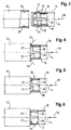
- FIG. 3 shows the contact sleeve 10 according to the invention with a corresponding mating connector 32 immediately before mating.
- Contact sleeve 10 and mating connector 32 are aligned with their respective longitudinal axes aligned and are moved to plug axially towards each other in the direction of arrow 36 toward each other.
- Fig. 4 the first mechanical contact between contact sleeve 10 and mating connector 32 is shown.
- the elevations 20 of a first pair of contact spring blades 18 contact the inner surface 30 of the mating connector 32, as indicated by arrows 34, at the same time the elevations 20 of the other two pairs of Maisfederlamellen 18 are still axially spaced from the inner surface 30 of the mating connector 32, so that these still have no mechanical contact with the mating connector 32.
- the contact spring blades 18 of the first pair of contact spring blades 18 must be deflected radially inwardly, which accordingly requires less force than if all contact spring blades 18 of all pairs of contact spring blades 18 would have to be deflected radially inward simultaneously.
- the contact spring blades 18 of the first pair of contact spring blades 18 contribute only with a frictional resistance to the insertion force, so that overall the insertion force is smaller even at this stage of mating, as if all Jardinfederlamellen 18 of all pairs of contact spring blades 18 would have to be deflected radially inwardly simultaneously ,
- Fig. 6 are now the contact spring blades 18 of the second pair of contact spring blades 18 already completely deflected radially inward and the elevations 20 of the third pair contact spring blades 18 now mechanically contact the inner surface 30 of the mating connector 32, as indicated by arrow 40.
- the contact spring blades 18 of the second pair of contact spring blades 18 now contribute as well as the contact spring blades 18 of the first pair of contact spring blades 18 only with a Reibungswiederstand to the insertion force. Accordingly, only the contact spring blades 18 of the third pair of contact spring blades 18 must be deflected radially inwards at this stage of the mating. Furthermore, overall, the insertion force is smaller even at this stage of the mating, as if all contact spring blades 18 of all pairs of contact spring blades 18 would have to be simultaneously deflected radially inwardly.
- the predetermined axial offset length 26 is, for example, 0.1 mm to 0.3 mm. In the illustrated embodiment, the axial offset length 26 has a value of 0.2 mm.
Landscapes
- Details Of Connecting Devices For Male And Female Coupling (AREA)
- Coupling Device And Connection With Printed Circuit (AREA)
Abstract
Description
- Die Erfindung betrifft eine Kontakthülse in Form eines Hohlzylinders mit einer Mantelfläche und einer Mittellängsachse für einen elektrischen Steckverbinder zum Herstellen eines elektrischen Kontaktes mit einem Gegensteckverbinder, wobei die Kontakthülse an deren Mantelfläche mindestens zwei Paar Kontaktfederlamellen aufweist, wobei jedes Paar Kontaktfederlamellen an der Kontakthülse radial gegenüberliegend angeordnet ist, wobei jede Kontaktfederlamelle eine radiale Erhebung aufweisen, welche eine elektrische Kontaktfläche ausbildet, wobei die Erhebungen eines Paares gegenüberliegender Kontaktfederlamellen in axialer Richtung bezüglich der Kontakthülse an derselben Stelle derart angeordnet sind, dass deren Kontaktflächen auf einer Geraden liegen, die die Mittellängsachse der Kontakthülse senkrecht schneidet, gemäß dem Oberbegriff des Patentanspruchs 1.
- Steckverbinder, insbesondere Koaxial-Steckverbinder, dienen der lösbaren Verbindung von Koaxialkabeln. Koaxial-Steckverbinder sind wie Koaxialkabel koaxial ausgeführt, damit sie die Vorteile der Koaxialkabel aufweisen, nämlich geringe elektromagnetische Beeinflussung und Abstrahlung sowie gute elektrische Abschirmung sowie eine Impedanz, die derjenigen des angeschlossenen Koaxialkabels entspricht, um Reflexionen an der Übergangsstelle zwischen Koaxial- Steckverbinder und Koaxialkabel zu vermeiden. Unter einem Koaxialkabel, kurz auch Koaxialkabel, wird dabei ein zweipoliges Kabel mit konzentrischem Aufbau verstanden, das einen Innenleiter (auch Seele genannt) aufweist, der in konstantem Abstand von einem hohlzylindrischen Außenleiter umgeben ist. Der Außenleiter schirmt den Innenleiter vor elektromagnetischer Störstrahlung ab. In dem Zwischenraum zwischen dem Innenleiter und dem Außenleiter ist ein Isolator oder Dielektrikum angeordnet.
- Koaxial-Steckverbinder sind dazu ausgebildet, einen vorbestimmten Wellenwiderstand, z. B. vom 50 Ω, bereitzustellen, um eine reflexionsfreie Übertragung von HF-Signalen zu gewährleisten. Der Wellenwiderstand eines Koaxial-Steckverbinders hängt u. a. von dem Verhältnis des Innendurchmessers des Außenleiters und dem Durchmesser des Innenleiters ab. Eine elektrische Anbindung eines Koaxialkabels an einen Koaxial-Steckverbinder erfordert daher an die jeweiligen Innendurchmesser und Außendurchmesser des Koaxialkabels angepasste Koaxial-Steckverbinder.
- Aus der
US 4 550 972 A ist ein buchsenförmiges Stanzbiegeteil als Kontaktbuchse zum Zusammenstecken mit einem Kontaktstift (contact pin) an einem steckseitigen Ende bekannt. wobei die Kontaktbuchse einen zylindrischen Abschnitt zwischen zwei Ringen aufweist. Dieser zylindrische Abschnitt setzt sich zusammen aus mehreren Paaren von sich in axialer Richtung erstreckenden Kontaktfederlamellen (beams). Jede Kontaktfederlamelle weist eine sich einwärts erhebende, sphärische Kontaktfläche (spherical contact boss) auf. Die Kontaktflächen eines gegenüberliegenden Paares von Kontaktfederlamellen sind in gleichem Abstand vom steckseitigen Ende angeordnet wobei die Kontaktflächen auf den Kontaktfederlamellen beide um eine etwas größere Distanz von dem steckseitigen Ende angeordnet sind. - Die Druckschrift
DE 20 2015 006 807 U1 betrifft ein Kontaktlamellenteil sowie einen Steckverbinder mit Kontaktlamellenteil. Das Kontaktlamellenteil weist eine Mehrzahl von etwa parallel nebeneinander verlaufenden Kontaktlamellen auf, die sich jeweils zwischen einem ersten Verbindungskörper in Form eines Trägerstreifens und einem zweiten Verbindungskörper in Form eines Trägerstreifens erstrecken. Die Kontaktlamellen erstrecken sich jeweils stegartig in einer Längsrichtung L, während sich die einteilig damit gebildeten Verbindungskörper etwa senkrecht dazu in der Querrichtung erstrecken. Die Querrichtung und die Längsrichtung spannen eine Lamellenebene auf, die der Papierebene entspricht. Durch ringförmiges Aufrollen der Trägerstreifen mit den dazwischen verlaufenden Kontaktlamellen wird ein gerader Lamellenkäfig gebildet. Jede Kontaktlamelle weist eine Kontaktzone zum Kontaktieren jeweils zweier Kontaktelemente auf. Die Kontaktzonen jeweils zweier benachbarter Kontaktlamellen sind in der Längsrichtung versetzt zueinander angeordnet. Hierdurch ergibt sich insgesamt eine alternierende Anordnung von Kontaktzonen in der Erstreckungsrichtung der Verbindungskörper. - Die Druckschrift
US 8 821 170 B1 zeigt eine elektrische Kontaktbuchse mit Kontaktfederlamellen, die jeweils als elektrischer Kontakt dienende Knickbereiche 2 aufweisen. Die Knickbereiche benachbarter Kontaktfederlamellen sind in axialer Richtung voneinander beabstandet. - Die Druckschrift
US 5 667 413 A betrifft eine elektrische Kontaktbuchse mit einem Kontaktkäfig, welcher mehrere Kontaktfederlamellen aufweist. Jede Kontaktfederlamelle weist einen Kontaktpunkt auf, welcher von einem gebogenen und sich dadurch radial einwärts erhebenden Teil der Federlamelle selbst ausgebildet ist. Die Kontaktpunkte von benachbarten Kontaktfederlamellen sind in Längsrichtung relativ zueinander beabstandet. - Der Erfindung liegt die Aufgabe zugrunde, eine Kontakthülse hinsichtlich der manuellen Handhabung beim Stecken mit einem Gegensteckverbinder zu verbessern.
- Diese Aufgabe wird erfindungsgemäß durch eine Kontakthülse der o. g. Art mit den in Anspruch 1 gekennzeichneten Merkmalen gelöst. Vorteilhafte Ausgestaltungen der Erfindung sind in den weiteren Ansprüchen beschrieben.
- Dazu ist es bei einer Kontakthülse der o. g. Art erfindungsgemäß vorgesehen, dass die axiale Versatzlänge zwischen den Erhebungen axial benachbarter Paare von Kataktfederlamellen 0,1 mm bis 0,3 mm beträgt und dass die Kontaktflächen rechteckig ausgebildet sind und sich rechtwinklig zur Mittellängsachse erstrecken.
- Dies hat den Vorteil, dass beim Einstecken der Kontakthülse in einen Gegenstecker in axialer Richtung die Erhebungen erst nacheinander den Gegenstecker mechanisch und elektrisch kontaktieren, so dass Steckkräfte reduziert sind, wobei eine Abstufung der Steckkraft beim Einstecken der Kontakthülse in einen Gegenstecker erzielt wird.
- Zum entsprechenden elektrischen und mechanischen Kontaktieren des Gegensteckers radial innen oder außen bezüglich der Kontakthülse erheben sich die Erhebungen radial nach innen und/oder außen über die Kontakthülse bzw. über die Mantelwandung hinaus.
- Eine besonders gute Reduzierung der Steckkräfte bei gleichzeitig vielen elektrischen Kontaktflächen erzielt man dadurch, dass drei Paar Kontaktfederlamellen mit jeweiligen Erhebungen an der Kontakthülse ausgebildet sind, wobei die Erhebungen eines jeden Paares zu den Erhebungen aller anderen Paare relativ in axialer Richtung versetzt angeordnet ist.
- Eine besonders einfach herzustellende Kontakthülse erzielt man dadurch, dass die Kontaktfederlamellen durch in Umfangsrichtung voneinander beabstandete angeordnete Ausnehmungen in der Kontakthülse bzw. der Mantelwandung der Kontakthülse ausgebildet sind.
- Besonders stabile und mechanisch widerstandsfähige Kontaktfederlamellen mit gleichzeitig hohen Federkräften für einen guten elektrischen Kontakt mit hoher Kontaktkraft erzielt man dadurch, dass die Kontaktfederlamellen an beiden axialen Enden formschlüssig mit der Kontakthülse bzw. mit der Mantelwandung der Kontakthülse verbunden sind.
- Eine Kontaktfläche mit geringen mechanischen Spannungen beim Einfedern der Kontaktfederlamellen erzielt man dadurch, dass die Erhebungen bogenförmig ausgebildet sind.
- Eine besonders vorteilhafte Abstufung der Steckkraft beim Einstecken der Kontakthülse in einen Gegenstecker erzielt man dadurch, dass die axiale Versatzlänge zwischen den Erhebungen verschiedener bzw. axial benachbarter Paare von Kontaktfederlamellen 0,2 mm, bzw. ein Vielfaches hiervon beträgt.
- Eine symmetrische Anordnung der Kontaktfederlamellen an der Kontakthülse erzielt man dadurch, dass n, mit n ≥ 2, Paare von Kontaktfederlamellen an der Kontakthülse ausgebildet sind, wobei die Kontaktfederlamellen in Umfangsrichtung um einen Winkel von 360 (2*n) voneinander beabstandet sind.
- Die Erfindung wird im Folgenden anhand der Zeichnung näher erläutert. Diese zeigt in
- Fig. 1
- eine bevorzugte Ausführungsform einer erfindungsgemäßen Kontakthülse in Seitenansicht;
- Fig. 2
- die bevorzugte Ausführungsform einer erfindungsgemäßen Kontakthülse gemäß
Fig. 1 in perspektivischer Ansicht; - Fig. 3
- die bevorzugte Ausführungsform einer erfindungsgemäßen Kontakthülse gemäß
Fig. 1 in Seitenansicht vor einem Einstecken in einen Gegensteckverbinder; - Fig. 4
- die bevorzugte Ausführungsform einer erfindungsgemäßen Kontakthülse gemäß
Fig. 1 in Seitenansicht bei dem Einstecken in einen Gegensteckverbinder in einem ersten teilgesteckten Zustand; - Fig. 5
- die bevorzugte Ausführungsform einer erfindungsgemäßen Kontakthülse gemäß
Fig. 1 in Seitenansicht bei dem Einstecken in einen Gegensteckverbinder in einem zweiten teilgesteckten Zustand und - Fig. 6
- die bevorzugte Ausführungsform einer erfindungsgemäßen Kontakthülse gemäß
Fig. 1 in Seitenansicht bei dem Einstecken in einen Gegensteckverbinder in einem vollständig gesteckten Zustand. - Die in
Fig. 1 und 2 dargestellte bevorzugte Ausführungsform einer erfindungsgemäßen Kontakthülse 10 ist in der Form eines Hohlzylinders mit Mantelwandung 12 und einer Mittellängsachse 14 ausgebildet. Durch in Umfangsrichtung gleichmäßig voneinander beabstandete Ausnehmungen 16 sind drei Paare von Kontaktfederlamellen 18 ausgebildet, wobei jeweils die beiden Kontaktfederlamellen 18 eines Paares radial gegenüberliegend an der Mantelwandung 12 angeordnet sind. Jede Kontaktfederlamelle 18 erstreckt sich in axialer Richtung im Wesentlichen parallel zu der Mittellängsachse 14. Jeweilige axiale Enden einer jeden Kontaktfederlamelle 18 sind formschlüssig mit der Mantelwandung 12 der Kontakthülse 10 ausgebildet. - Jede Kontaktfederlamelle 18 weist eine radiale Erhebung 20 auf die bogenförmig ausgebildet ist. In dem dargestellten Ausführungsbeispiel ragen die Erhebung radial nach außen über die Mantelwandung 12 der Kontakthülse 10 hinaus. Jede radiale Erhebung bildet an deren höchsten Stelle eine Kontaktfläche 22 aus (mit gestrichelten Linien angedeutet), welche zum elektrischen und mechanischen Kontaktieren eines Gegensteckverbinders ausgebildet ist. In dem dargestellten Ausführungsbeispiel sind die Kontaktflächen 22 rechteckig ausgebildet und erstrecken sich im Wesentlichen rechtwinklig zur Mittellängsachse 14. Die Erhebungen eines Paares von radial gegenüberliegenden Kontaktfederlamelle 18 befinden sich auf einer Geraden 24, welche die Mittellängsachse 14 in einem rechten Winkel schneidet.
- Die Erhebungen 20 bzw. Kontaktflächen 22 verschiedener Paare von Kontaktfederlamellen 18 sind in axialer Richtung bezüglich der Kontakthülse 10 um eine vorbestimmte axiale Versatzlänge 26 voneinander beabstandet bzw. versetzt. In dem vorliegenden Beispiel gemäß der
Fig. 1 und 2 sind drei Paare von Kontaktfederlamellen 18 an der Kontakthülse 10 angeordnet und die jeweiligen Kontaktflächen 22 sind um die axiale Versatzlänge 26 voneinander axial beabstandet. Diese axiale Versatzlänge 26 erstreckt sich im Wesentlichen parallel zu der Mittellängsachse 14. - In dem dargestellten Ausführungsbeispiel ist die Kontakthülse 10 als Stanz-Biegeteil ausgebildet und weist dementsprechend einen Fügeschlitz 28 auf. Weiterhin ist die Kontakthülse 10 aus einem elektrisch leitfähigen und federelastischen Werkstoff hergestellt, so dass die Kontaktfederlamellen 18 elastisch federnd auslenkbar sind. Beim Einstecken der Kontakthülse 10, wie in den
Fig. 3 bis 6 dargestellt, kontaktieren die Kontaktflächen 22 der Erhebungen 20 eine Innenfläche 30 (Fig. 3 ) eines Gegensteckverbinders 32 (Fig. 3 ) derart, dass die entsprechend zu der Erhebungen 20 gehörende Kontaktfederlamelle 18 federelastisch radial nach innen ausgelenkt wird. Die sich hierdurch ergebende Rückstellkraft der Kontaktfederlamelle 18 erzeugt dementsprechend eine Kontaktkraft, mit der die Kontaktfläche 2 gegen die Innenseite 30 des Gegensteckverbinders 32 gedrückt wird, so dass ein elektrischer Kontakt zwischen der Kontaktfederlamelle 18 und der Innenseite 30 des Gegensteckverbinders 32 mit Kontaktkraft und Kontaktfläche 22 ausgebildet ist. Ein entsprechender Kontaktdruck ergibt sich dann aus dem Quotienten aus Kontaktkraft zu Kontaktfläche 22. - Beim Einstecken der Kontakthülse 10 in den Gegensteckverbinder 32 werden also die Kontaktfederlamellen 18 radial nach innen ausgelenkt, was zu einer entsprechenden notwendigen Steckkraft führt, die beim Einstecken der Kontakthülse 10 in den Gegensteckverbinder 32 überwunden werden muss. Da erfindungsgemäß die Erhebungen 20 axial versetzt zueinander angeordnet sind, ist diese notwendige Steckkraft reduziert.
- Der Steckvorgang wird nachfolgend anhand der
Fig. 3 bis 6 erläutert. DieFig. 3 zeigt die erfindungsgemäße Kontakthülse 10 mit einem entsprechenden Gegensteckverbinder 32 unmittelbar vor dem Zusammenstecken. Kontakthülse 10 und Gegensteckverbinder 32 sind mit deren jeweiligen Längsachsen fluchten ausgerichtet und werden zum Stecken axial in Pfeilrichtung 36 aufeinander zu bewegt. - In
Fig. 4 ist der erste mechanische Kontakt zwischen Kontakthülse 10 und Gegensteckverbinder 32 dargestellt. Hierbei kontaktieren die Erhebungen 20 eines ersten Paares von Kontaktfederlamellen 18 die Innenfläche 30 des Gegensteckverbinders 32, wie mit Pfeilen 34 gekennzeichnet, wobei gleichzeitig die Erhebungen 20 der anderen beiden Paare von Kontaktfederlamellen 18 noch axial von der Innenfläche 30 des Gegensteckverbinders 32 beabstandet sind, so dass diese noch keinen mechanischen Kontakt zum Gegensteckverbinder 32 haben. Dementsprechend müssen beim Einstecken nur die Kontaktfederlamellen 18 des ersten Paares von Kontaktfederlamellen 18 radial nach innen ausgelenkt werden, was dementsprechend eine geringere Kraft erfordert, als wenn alle Kontaktfederlamellen 18 aller Paare von Kontaktfederlamellen 18 gleichzeitig radial nach innen ausgelenkt werden müssten. - In
Fig. 5 sind die Kontaktfederlamellen 18 des ersten Paares von Kontaktfederlamellen 18 bereits vollständig radial nach innen ausgelenkt und die Erhebungen 20 eines zweiten Paares von Kontaktfederlamellen 18 kontaktieren mechanisch die Innenfläche 30 des Gegensteckverbinders 32, wie mit Pfeil 38 gekennzeichnet. Dementsprechend müssen beim weiteren Einstecken der Kontakthülse 10 in den Gegensteckverbinder 32 nur die Kontaktfederlamellen 18 des zweiten Paares von Kontaktfederlamellen 18 radial nach innen ausgelenkt werden. Gleichzeitig sind die Erhebungen 20 des verbleibenden dritten Paares von Kontaktfederlamellen 18 noch axial von der Innenfläche 30 des Gegensteckverbinders 32 beabstandet, so dass diese noch keinen mechanischen Kontakt zum Gegensteckverbinder 32 haben. Die Kontaktfederlamellen 18 des ersten Paares von Kontaktfederlamellen 18 tragen nur noch mit einem Reibungswiderstand zur Steckkraft bei, so dass insgesamt die Steckkraft auch in diesem Stadium des Zusammensteckens kleiner ist, als wenn alle Kontaktfederlamellen 18 aller Paare von Kontaktfederlamellen 18 gleichzeitig radial nach innen ausgelenkt werden müssten. - In
Fig. 6 sind nun auch die Kontaktfederlamellen 18 des zweiten Paares von Kontaktfederlamellen 18 bereits vollständig radial nach innen ausgelenkt und die Erhebungen 20 des dritten Paares von Kontaktfederlamellen 18 kontaktieren nun mechanisch die Innenfläche 30 des Gegensteckverbinders 32, wie mit Pfeil 40 gekennzeichnet. Die Kontaktfederlamellen 18 des zweiten Paares von Kontaktfederlamellen 18 tragen nun ebenso wie die Kontaktfederlamellen 18 des ersten Paares von Kontaktfederlamellen 18 nur noch mit einem Reibungswiederstand zur Steckkraft bei. In diesem Stadium des Zusammensteckens müssen dementsprechend nur die Kontaktfederlamellen 18 des dritten Paares von Kontaktfederlamellen 18 radial nach innen ausgelenkt werden. Weiterhin ist insgesamt die Steckkraft auch in diesem Stadium des Zusammensteckens kleiner, als wenn alle Kontaktfederlamellen 18 aller Paare von Kontaktfederlamellen 18 gleichzeitig radial nach innen ausgelenkt werden müssten. - Im Ergebnis ergibt sich somit durch die axial versetzte Anordnung der Erhebungen 20 der Paare von Kontaktfederlamellen 18 über den gesamten axialen Steckweg eine reduzierte Steckkraft im Vergleich zu einem Steckvorgang, bei dem alle Kontaktfederlamellen 18 aller Paare von Kontaktfederlamellen 18 gleichzeitig radial nach innen ausgelenkt werden müssen.
- Die vorbestimmte axiale Versatzlänge 26 beträgt beispielsweise 0,1 mm bis 0,3 mm. In dem dargestellten Ausführungsbeispiel hat die axiale Versatzlänge 26 einen Wert von 0,2 mm.
Claims (7)
- Kontakthülse (10) in Form eines Hohlzylinders mit einer Mantelwandung (12) und einer Mittellängsachse (14) für einen elektrischen Steckverbinder zum Herstellen eines elektrischen Kontaktes mit einem Gegensteckverbinder (32), wobei die Kontakthülse (10) an deren Mantelwandung (12) mindestens zwei Paar Kontaktfederlamellen (18) aufweist, wobei die Kontaktfederlamellen (18) eines Paares an der Kontakthülse (10) radial gegenüberliegend angeordnet sind, wobei jede Kontaktfederlamelle (18) eine radiale Erhebung (20) aufweisen, welche eine elektrische Kontaktfläche (22) ausbildet, wobei die Erhebungen (20) eines Paares gegenüberliegender Kontaktfederlamellen (18) in axialer Richtung bezüglich der Kontakthülse (10) an derselben Stelle derart angeordnet sind, dass deren Kontaktflächen (22) auf einer Geraden (24) liegen, die die Mittellängsachse (14) der Kontakthülse (10) senkrecht schneidet,
dadurch gekennzeichnet, dass die Erhebungen (20) von mindestens einem ersten Paar von Kontaktfederlamellen (18) relativ zu den Erhebungen (20) von mindestens einem zweiten Paar von Kontaktfederlamellen (18) in axialer Richtung bezüglich der Kontakthülse (10) um eine vorbestimmte axiale Versatzlänge (26) versetzt angeordnet sind, wobei sich die Erhebungen (20) radial nach außen über die Kontakthülse (10) erheben. - Kontakthülse (10) nach Anspruch 1, dadurch gekennzeichnet, dass drei Paar Kontaktfederlamellen (18) mit jeweiligen Erhebungen (20) an der Kontakthülse (10) ausgebildet sind, wobei die Erhebungen (20) eines jeden Paares relativ zu den Erhebungen (20) aller anderen Paare in axialer Richtung versetzt angeordnet ist.
- Kontakthülse (10) nach mindestens einem der vorhergehenden Ansprüche, dadurch gekennzeichnet, dass die Kontaktfederlamellen (18) durch in Umfangsrichtung voneinander beabstandete angeordnete Ausnehmungen (16) in der Kontakthülse (10) ausgebildet sind.
- Kontakthülse (10) nach mindestens einem der vorhergehenden Ansprüche, dadurch gekennzeichnet, dass die Kontaktfederlamellen (18) an beiden axialen Enden formschlüssig mit der Kontakthülse (10) verbunden sind.
- Kontakthülse (10) nach mindestens einem der vorhergehenden Ansprüche, dadurch gekennzeichnet, dass die Erhebungen (20) bogenförmig ausgebildet sind.
- Kontakthülse (10) nach mindestens einem der vorhergehenden Ansprüche, dadurch gekennzeichnet, dass die axiale Versatzlänge (26) zwischen den Erhebungen (20) axial benachbarter Paare von Kontaktfederlamellen (18) 0,1 mm bis 0,3 mm, insbesondere 0,2 mm, beträgt.
- Kontakthülse (10) nach mindestens einem der vorhergehenden Ansprüche, dadurch gekennzeichnet, dass n, mit n > 2, Paare von Kontaktfederlamellen (18) an der Kontakthülse (10) ausgebildet sind, wobei die Kontaktfederlamellen (18) in Umfangsrichtung um einen Winkel von 360 (2*n) voneinander beabstandet sind.
Priority Applications (1)
| Application Number | Priority Date | Filing Date | Title |
|---|---|---|---|
| EP19182255.0A EP3579348B1 (de) | 2016-02-26 | 2016-02-26 | Kontakthülse für einen elektrischen steckverbinder |
Applications Claiming Priority (3)
| Application Number | Priority Date | Filing Date | Title |
|---|---|---|---|
| EP16706533.3A EP3227970B1 (de) | 2016-02-26 | 2016-02-26 | Kontakthülse für einen elektrischen steckverbinder |
| PCT/EP2016/000336 WO2017144069A1 (de) | 2016-02-26 | 2016-02-26 | Kontakthülse für einen elektrischen steckverbinder |
| EP19182255.0A EP3579348B1 (de) | 2016-02-26 | 2016-02-26 | Kontakthülse für einen elektrischen steckverbinder |
Related Parent Applications (2)
| Application Number | Title | Priority Date | Filing Date |
|---|---|---|---|
| EP16706533.3A Division EP3227970B1 (de) | 2016-02-26 | 2016-02-26 | Kontakthülse für einen elektrischen steckverbinder |
| EP16706533.3A Division-Into EP3227970B1 (de) | 2016-02-26 | 2016-02-26 | Kontakthülse für einen elektrischen steckverbinder |
Publications (2)
| Publication Number | Publication Date |
|---|---|
| EP3579348A1 true EP3579348A1 (de) | 2019-12-11 |
| EP3579348B1 EP3579348B1 (de) | 2021-08-04 |
Family
ID=55442761
Family Applications (2)
| Application Number | Title | Priority Date | Filing Date |
|---|---|---|---|
| EP16706533.3A Active EP3227970B1 (de) | 2016-02-26 | 2016-02-26 | Kontakthülse für einen elektrischen steckverbinder |
| EP19182255.0A Active EP3579348B1 (de) | 2016-02-26 | 2016-02-26 | Kontakthülse für einen elektrischen steckverbinder |
Family Applications Before (1)
| Application Number | Title | Priority Date | Filing Date |
|---|---|---|---|
| EP16706533.3A Active EP3227970B1 (de) | 2016-02-26 | 2016-02-26 | Kontakthülse für einen elektrischen steckverbinder |
Country Status (7)
| Country | Link |
|---|---|
| US (1) | US10224659B2 (de) |
| EP (2) | EP3227970B1 (de) |
| KR (1) | KR102094628B1 (de) |
| CN (3) | CN108701928A (de) |
| DE (1) | DE112016006492A5 (de) |
| TW (1) | TW201806255A (de) |
| WO (1) | WO2017144069A1 (de) |
Families Citing this family (21)
| Publication number | Priority date | Publication date | Assignee | Title |
|---|---|---|---|---|
| KR20180113539A (ko) * | 2016-02-26 | 2018-10-16 | 로젠버거 호흐프리쿠벤츠테흐닉 게엠베하 운트 코. 카게 | 전기 플러그 커넥터 |
| CN108701928A (zh) * | 2016-02-26 | 2018-10-23 | 罗森伯格高频技术有限及两合公司 | 用于电插头连接器的接触套筒 |
| DE102016123081B4 (de) * | 2016-11-30 | 2018-06-14 | Amphenol-Tuchel Electronics Gmbh | Zylindrische Hochstromkontakt-Steckverbinder-Buchse |
| US10992087B2 (en) | 2018-12-13 | 2021-04-27 | Amphenol Corporation | Contact member for electrical connector |
| DE102019114646A1 (de) | 2019-05-31 | 2020-12-03 | Te Connectivity Germany Gmbh | Steckverbindersystem |
| EP3761455B1 (de) * | 2019-07-01 | 2022-06-22 | ODU GmbH & Co. KG | Verbindungsstecker mit zentralem stift und lamellenhülse und einer verbindungsbuchse mit lamellenhülse |
| EP3783754A1 (de) * | 2019-08-20 | 2021-02-24 | Aptiv Technologies Limited | Verbinder für automobilanwendungen |
| US11075488B2 (en) | 2019-11-25 | 2021-07-27 | TE Connectivity Services Gmbh | Impedance control connector with dielectric seperator rib |
| US11146010B2 (en) | 2019-12-09 | 2021-10-12 | TE Connectivity Services Gmbh | Overmolded contact assembly |
| US11011875B1 (en) | 2019-12-10 | 2021-05-18 | TE Connectivity Services Gmbh | Electrical cable braid positioning clip |
| US10978832B1 (en) | 2020-02-07 | 2021-04-13 | TE Connectivity Services Gmbh | Protection member to protect resilient arms of a contact assembly from stubbing |
| US11296464B2 (en) | 2020-02-14 | 2022-04-05 | TE Connectivity Services Gmbh | Impedance control connector |
| EP3923421A1 (de) * | 2020-06-09 | 2021-12-15 | Afag Holding AG | Elektrische verbindungseinrichtung mit einem grundkörper und einem verschiebekörper |
| CN213782405U (zh) * | 2020-10-30 | 2021-07-23 | 泰科电子(上海)有限公司 | 高压连接器及用于高压连接器的电磁屏蔽壳 |
| US12170424B2 (en) | 2021-08-11 | 2024-12-17 | Te Connectivity Germany Gmbh | Contact of an electrical connector with protection tabs for cantilever beams |
| WO2023034396A1 (en) | 2021-09-01 | 2023-03-09 | Fci Usa Llc | High speed, ruggedized connector |
| JP7348258B2 (ja) | 2021-12-20 | 2023-09-20 | 日本航空電子工業株式会社 | 端子 |
| CN115133351B (zh) * | 2022-06-22 | 2025-02-14 | 中航光电科技股份有限公司 | 一种射频同轴连接器及其屏蔽套筒 |
| CN218602858U (zh) * | 2022-10-17 | 2023-03-10 | 深圳亚力盛连接器有限公司 | 一种h-mtd公端连接器的环形弹片结构 |
| CN218548994U (zh) * | 2022-10-17 | 2023-02-28 | 深圳亚力盛连接器有限公司 | 一种h-mtd公端连接器的接地弹片结构 |
| FR3165116A1 (fr) | 2024-07-25 | 2026-01-30 | Raydiall Sas | Corps de blindage électromagnétique pour connecteur de transmission de signaux électriques et/ou de données et/ou de signaux radiofréquences (RF), comprenant des pattes flexibles radialement à deux profils différents dont un à bossage destiné à former un point de contact électrique. |
Citations (7)
| Publication number | Priority date | Publication date | Assignee | Title |
|---|---|---|---|---|
| US4550972A (en) | 1984-04-09 | 1985-11-05 | Amp Incorporated | Cylindrical socket contact |
| US5269711A (en) * | 1991-06-17 | 1993-12-14 | Gte Products Corp. | Antenna connector |
| US5556292A (en) * | 1994-04-22 | 1996-09-17 | Smk Corporation | Cable connector |
| US5667413A (en) | 1995-11-13 | 1997-09-16 | Alcoa Fujikura Ltd. | Socket-type electrical connector |
| EP0858133A2 (de) * | 1996-09-19 | 1998-08-12 | Itt Manufacturing Enterprises, Inc. | Körper eines Koaxialverbinderns |
| US8821170B1 (en) | 2012-07-19 | 2014-09-02 | Robert Hla Thein | Electrical contact having multiple cantilevered beams |
| DE202015006807U1 (de) | 2015-09-29 | 2015-10-27 | Rosenberger Hochfrequenztechnik Gmbh & Co. Kg | Kontaktlamellenteil sowie Steckverbinder mit Kontaktlamellenteil |
Family Cites Families (19)
| Publication number | Priority date | Publication date | Assignee | Title |
|---|---|---|---|---|
| US4662706A (en) * | 1985-04-25 | 1987-05-05 | Elcon Products International Company | Electrical device |
| US4722704A (en) * | 1986-06-12 | 1988-02-02 | Amp Incorporated | High density socket contact receptacle |
| CN2162717Y (zh) * | 1993-03-12 | 1994-04-20 | 周文三 | 一种改进的汽车点烟器插头 |
| US5431576A (en) * | 1994-07-14 | 1995-07-11 | Elcon Products International | Electrical power connector |
| US5676571A (en) * | 1996-08-08 | 1997-10-14 | Elcon Products International | Socket contact with integrally formed hood and arc-arresting portion |
| US6299492B1 (en) * | 1998-08-20 | 2001-10-09 | A. W. Industries, Incorporated | Electrical connectors |
| DE19964299B4 (de) * | 1999-09-16 | 2004-02-26 | Spinner Gmbh Elektrotechnische Fabrik | Steckverbinder für abstrahlende Koaxialkabel |
| US6533617B1 (en) * | 2000-01-07 | 2003-03-18 | J. D'addario & Company, Inc. | Electrical plug connectors |
| CN2553532Y (zh) * | 2002-06-26 | 2003-05-28 | 章鸿斌 | 一种香蕉插头 |
| DE20311027U1 (de) * | 2003-07-17 | 2003-09-18 | Tsai Huang, Shun-Chih, Tainan | Signalstecker |
| DE102009030463A1 (de) * | 2009-06-25 | 2010-12-30 | Lapp Engineering & Co. | Elektrischer Steckverbinder |
| WO2012023041A1 (en) * | 2010-08-19 | 2012-02-23 | Fci Automotive Holding | Electrical power terminal |
| CN202111338U (zh) * | 2011-05-23 | 2012-01-11 | 罗森伯格亚太电子有限公司 | 一种同轴电缆连接器 |
| JP5541305B2 (ja) * | 2012-03-16 | 2014-07-09 | 第一精工株式会社 | プレスフィット用コネクタ端子 |
| DE102013213710B4 (de) * | 2013-07-12 | 2019-09-05 | Samsung Sdi Co., Ltd. | Batteriesystem und Verfahren zur Herstellung eines Batteriesystems |
| CN103490200B (zh) * | 2013-09-27 | 2015-07-29 | 苏州华旃航天电器有限公司 | 一种具有冲压接触元件的射频同轴电连接器 |
| CN204424520U (zh) * | 2015-01-15 | 2015-06-24 | 苏州工业园区丰年科技有限公司 | 一种线缆连接器 |
| CN204424526U (zh) * | 2015-02-13 | 2015-06-24 | 常州市新盛电器有限公司 | 公头单元射频连接器 |
| CN108701928A (zh) * | 2016-02-26 | 2018-10-23 | 罗森伯格高频技术有限及两合公司 | 用于电插头连接器的接触套筒 |
-
2016
- 2016-02-26 CN CN201680082383.9A patent/CN108701928A/zh active Pending
- 2016-02-26 US US16/060,494 patent/US10224659B2/en active Active
- 2016-02-26 DE DE112016006492.6T patent/DE112016006492A5/de not_active Withdrawn
- 2016-02-26 CN CN202110770725.9A patent/CN113422226A/zh active Pending
- 2016-02-26 EP EP16706533.3A patent/EP3227970B1/de active Active
- 2016-02-26 KR KR1020187023484A patent/KR102094628B1/ko active Active
- 2016-02-26 CN CN202110842023.7A patent/CN113571936A/zh active Pending
- 2016-02-26 WO PCT/EP2016/000336 patent/WO2017144069A1/de not_active Ceased
- 2016-02-26 EP EP19182255.0A patent/EP3579348B1/de active Active
-
2017
- 2017-01-24 TW TW106102738A patent/TW201806255A/zh unknown
Patent Citations (7)
| Publication number | Priority date | Publication date | Assignee | Title |
|---|---|---|---|---|
| US4550972A (en) | 1984-04-09 | 1985-11-05 | Amp Incorporated | Cylindrical socket contact |
| US5269711A (en) * | 1991-06-17 | 1993-12-14 | Gte Products Corp. | Antenna connector |
| US5556292A (en) * | 1994-04-22 | 1996-09-17 | Smk Corporation | Cable connector |
| US5667413A (en) | 1995-11-13 | 1997-09-16 | Alcoa Fujikura Ltd. | Socket-type electrical connector |
| EP0858133A2 (de) * | 1996-09-19 | 1998-08-12 | Itt Manufacturing Enterprises, Inc. | Körper eines Koaxialverbinderns |
| US8821170B1 (en) | 2012-07-19 | 2014-09-02 | Robert Hla Thein | Electrical contact having multiple cantilevered beams |
| DE202015006807U1 (de) | 2015-09-29 | 2015-10-27 | Rosenberger Hochfrequenztechnik Gmbh & Co. Kg | Kontaktlamellenteil sowie Steckverbinder mit Kontaktlamellenteil |
Also Published As
| Publication number | Publication date |
|---|---|
| KR20180113531A (ko) | 2018-10-16 |
| DE112016006492A5 (de) | 2018-11-15 |
| EP3579348B1 (de) | 2021-08-04 |
| CN113422226A (zh) | 2021-09-21 |
| CN113571936A (zh) | 2021-10-29 |
| US10224659B2 (en) | 2019-03-05 |
| KR102094628B1 (ko) | 2020-03-30 |
| TW201806255A (zh) | 2018-02-16 |
| US20180366856A1 (en) | 2018-12-20 |
| CN108701928A (zh) | 2018-10-23 |
| EP3227970A1 (de) | 2017-10-11 |
| EP3227970B1 (de) | 2019-09-04 |
| WO2017144069A1 (de) | 2017-08-31 |
Similar Documents
| Publication | Publication Date | Title |
|---|---|---|
| EP3227970B1 (de) | Kontakthülse für einen elektrischen steckverbinder | |
| EP3420612B1 (de) | Elektrischer steckverbinder | |
| EP3357127B1 (de) | Kontaktlamellenteil | |
| EP3396793B1 (de) | Kontaktkörper für einen steckverbinder | |
| EP3227971B1 (de) | Hf-steckverbindung mit selbstschliessender kontakthülse | |
| EP3396791B1 (de) | Aussenleiteranordnung | |
| DE102014221970A1 (de) | Stifteinheit für ein Verbindergehäuse und Verbindergehäuse hiermit | |
| DE202010009598U1 (de) | Steckverbinder mit Außenleiterschirm | |
| WO2011113594A1 (de) | Hochstromsteckverbinder | |
| DE102016006598A1 (de) | Steckverbinder | |
| EP1730815A1 (de) | Koaxialsteckverbindung für leiterplatten mit gefedertem toleranzausgleich | |
| DE102021112143B4 (de) | Elektrisches Kontaktelement mit einem Stützring | |
| EP3627636A1 (de) | Elektrische steckverbindung, baugruppenverbindung und leiterplattenanordnung | |
| EP1680840A1 (de) | Flachsteckbuchse | |
| EP3605746A1 (de) | Steckverbinder sowie steckverbindung mit einem solchen steckverbinder | |
| EP3579346B1 (de) | Elektrischer steckverbinder für leiterplatten | |
| WO2018024462A1 (de) | Hermaphroditisches elektrisches kontaktelement | |
| EP3879641B1 (de) | Steckverbinderanordnung zum elektrischen verbinden zweier kabel | |
| WO1998043321A1 (de) | Steckerbuchse mit in der form eines hyperboloids angeordneten kontaktbereichen | |
| WO2022152410A1 (de) | Elektrische steckverbindung und leiterplattenanordnung | |
| EP2697867B1 (de) | Steckverbinder | |
| DE102005054590A1 (de) | Elektrischer Steckverbinder | |
| DE102022106159A1 (de) | Elektrische Kontakthülse mit geringer Steckkraft | |
| DE102023110351A1 (de) | Gestrickpresslingbuchsenkontakt und Steckverbinderanordnung | |
| DE202007014059U1 (de) | HF-Steckverbinder |
Legal Events
| Date | Code | Title | Description |
|---|---|---|---|
| PUAI | Public reference made under article 153(3) epc to a published international application that has entered the european phase |
Free format text: ORIGINAL CODE: 0009012 |
|
| STAA | Information on the status of an ep patent application or granted ep patent |
Free format text: STATUS: THE APPLICATION HAS BEEN PUBLISHED |
|
| AC | Divisional application: reference to earlier application |
Ref document number: 3227970 Country of ref document: EP Kind code of ref document: P |
|
| AK | Designated contracting states |
Kind code of ref document: A1 Designated state(s): AL AT BE BG CH CY CZ DE DK EE ES FI FR GB GR HR HU IE IS IT LI LT LU LV MC MK MT NL NO PL PT RO RS SE SI SK SM TR |
|
| STAA | Information on the status of an ep patent application or granted ep patent |
Free format text: STATUS: REQUEST FOR EXAMINATION WAS MADE |
|
| 17P | Request for examination filed |
Effective date: 20200602 |
|
| RBV | Designated contracting states (corrected) |
Designated state(s): AL AT BE BG CH CY CZ DE DK EE ES FI FR GB GR HR HU IE IS IT LI LT LU LV MC MK MT NL NO PL PT RO RS SE SI SK SM TR |
|
| GRAP | Despatch of communication of intention to grant a patent |
Free format text: ORIGINAL CODE: EPIDOSNIGR1 |
|
| STAA | Information on the status of an ep patent application or granted ep patent |
Free format text: STATUS: GRANT OF PATENT IS INTENDED |
|
| INTG | Intention to grant announced |
Effective date: 20210426 |
|
| GRAS | Grant fee paid |
Free format text: ORIGINAL CODE: EPIDOSNIGR3 |
|
| GRAA | (expected) grant |
Free format text: ORIGINAL CODE: 0009210 |
|
| STAA | Information on the status of an ep patent application or granted ep patent |
Free format text: STATUS: THE PATENT HAS BEEN GRANTED |
|
| AC | Divisional application: reference to earlier application |
Ref document number: 3227970 Country of ref document: EP Kind code of ref document: P |
|
| AK | Designated contracting states |
Kind code of ref document: B1 Designated state(s): AL AT BE BG CH CY CZ DE DK EE ES FI FR GB GR HR HU IE IS IT LI LT LU LV MC MK MT NL NO PL PT RO RS SE SI SK SM TR |
|
| REG | Reference to a national code |
Ref country code: GB Ref legal event code: FG4D Free format text: NOT ENGLISH |
|
| REG | Reference to a national code |
Ref country code: AT Ref legal event code: REF Ref document number: 1417962 Country of ref document: AT Kind code of ref document: T Effective date: 20210815 |
|
| REG | Reference to a national code |
Ref country code: CH Ref legal event code: EP |
|
| REG | Reference to a national code |
Ref country code: DE Ref legal event code: R096 Ref document number: 502016013567 Country of ref document: DE |
|
| REG | Reference to a national code |
Ref country code: IE Ref legal event code: FG4D Free format text: LANGUAGE OF EP DOCUMENT: GERMAN |
|
| REG | Reference to a national code |
Ref country code: SE Ref legal event code: TRGR |
|
| REG | Reference to a national code |
Ref country code: LT Ref legal event code: MG9D |
|
| REG | Reference to a national code |
Ref country code: NL Ref legal event code: MP Effective date: 20210804 |
|
| PG25 | Lapsed in a contracting state [announced via postgrant information from national office to epo] |
Ref country code: RS Free format text: LAPSE BECAUSE OF FAILURE TO SUBMIT A TRANSLATION OF THE DESCRIPTION OR TO PAY THE FEE WITHIN THE PRESCRIBED TIME-LIMIT Effective date: 20210804 Ref country code: FI Free format text: LAPSE BECAUSE OF FAILURE TO SUBMIT A TRANSLATION OF THE DESCRIPTION OR TO PAY THE FEE WITHIN THE PRESCRIBED TIME-LIMIT Effective date: 20210804 Ref country code: ES Free format text: LAPSE BECAUSE OF FAILURE TO SUBMIT A TRANSLATION OF THE DESCRIPTION OR TO PAY THE FEE WITHIN THE PRESCRIBED TIME-LIMIT Effective date: 20210804 Ref country code: BG Free format text: LAPSE BECAUSE OF FAILURE TO SUBMIT A TRANSLATION OF THE DESCRIPTION OR TO PAY THE FEE WITHIN THE PRESCRIBED TIME-LIMIT Effective date: 20211104 Ref country code: LT Free format text: LAPSE BECAUSE OF FAILURE TO SUBMIT A TRANSLATION OF THE DESCRIPTION OR TO PAY THE FEE WITHIN THE PRESCRIBED TIME-LIMIT Effective date: 20210804 Ref country code: HR Free format text: LAPSE BECAUSE OF FAILURE TO SUBMIT A TRANSLATION OF THE DESCRIPTION OR TO PAY THE FEE WITHIN THE PRESCRIBED TIME-LIMIT Effective date: 20210804 Ref country code: NO Free format text: LAPSE BECAUSE OF FAILURE TO SUBMIT A TRANSLATION OF THE DESCRIPTION OR TO PAY THE FEE WITHIN THE PRESCRIBED TIME-LIMIT Effective date: 20211104 Ref country code: PT Free format text: LAPSE BECAUSE OF FAILURE TO SUBMIT A TRANSLATION OF THE DESCRIPTION OR TO PAY THE FEE WITHIN THE PRESCRIBED TIME-LIMIT Effective date: 20211206 |
|
| PG25 | Lapsed in a contracting state [announced via postgrant information from national office to epo] |
Ref country code: PL Free format text: LAPSE BECAUSE OF FAILURE TO SUBMIT A TRANSLATION OF THE DESCRIPTION OR TO PAY THE FEE WITHIN THE PRESCRIBED TIME-LIMIT Effective date: 20210804 Ref country code: LV Free format text: LAPSE BECAUSE OF FAILURE TO SUBMIT A TRANSLATION OF THE DESCRIPTION OR TO PAY THE FEE WITHIN THE PRESCRIBED TIME-LIMIT Effective date: 20210804 Ref country code: GR Free format text: LAPSE BECAUSE OF FAILURE TO SUBMIT A TRANSLATION OF THE DESCRIPTION OR TO PAY THE FEE WITHIN THE PRESCRIBED TIME-LIMIT Effective date: 20211105 |
|
| PG25 | Lapsed in a contracting state [announced via postgrant information from national office to epo] |
Ref country code: NL Free format text: LAPSE BECAUSE OF FAILURE TO SUBMIT A TRANSLATION OF THE DESCRIPTION OR TO PAY THE FEE WITHIN THE PRESCRIBED TIME-LIMIT Effective date: 20210804 |
|
| PG25 | Lapsed in a contracting state [announced via postgrant information from national office to epo] |
Ref country code: DK Free format text: LAPSE BECAUSE OF FAILURE TO SUBMIT A TRANSLATION OF THE DESCRIPTION OR TO PAY THE FEE WITHIN THE PRESCRIBED TIME-LIMIT Effective date: 20210804 |
|
| REG | Reference to a national code |
Ref country code: DE Ref legal event code: R097 Ref document number: 502016013567 Country of ref document: DE |
|
| PG25 | Lapsed in a contracting state [announced via postgrant information from national office to epo] |
Ref country code: SM Free format text: LAPSE BECAUSE OF FAILURE TO SUBMIT A TRANSLATION OF THE DESCRIPTION OR TO PAY THE FEE WITHIN THE PRESCRIBED TIME-LIMIT Effective date: 20210804 Ref country code: SK Free format text: LAPSE BECAUSE OF FAILURE TO SUBMIT A TRANSLATION OF THE DESCRIPTION OR TO PAY THE FEE WITHIN THE PRESCRIBED TIME-LIMIT Effective date: 20210804 Ref country code: RO Free format text: LAPSE BECAUSE OF FAILURE TO SUBMIT A TRANSLATION OF THE DESCRIPTION OR TO PAY THE FEE WITHIN THE PRESCRIBED TIME-LIMIT Effective date: 20210804 Ref country code: EE Free format text: LAPSE BECAUSE OF FAILURE TO SUBMIT A TRANSLATION OF THE DESCRIPTION OR TO PAY THE FEE WITHIN THE PRESCRIBED TIME-LIMIT Effective date: 20210804 Ref country code: CZ Free format text: LAPSE BECAUSE OF FAILURE TO SUBMIT A TRANSLATION OF THE DESCRIPTION OR TO PAY THE FEE WITHIN THE PRESCRIBED TIME-LIMIT Effective date: 20210804 Ref country code: AL Free format text: LAPSE BECAUSE OF FAILURE TO SUBMIT A TRANSLATION OF THE DESCRIPTION OR TO PAY THE FEE WITHIN THE PRESCRIBED TIME-LIMIT Effective date: 20210804 |
|
| PLBE | No opposition filed within time limit |
Free format text: ORIGINAL CODE: 0009261 |
|
| STAA | Information on the status of an ep patent application or granted ep patent |
Free format text: STATUS: NO OPPOSITION FILED WITHIN TIME LIMIT |
|
| 26N | No opposition filed |
Effective date: 20220506 |
|
| PG25 | Lapsed in a contracting state [announced via postgrant information from national office to epo] |
Ref country code: SI Free format text: LAPSE BECAUSE OF FAILURE TO SUBMIT A TRANSLATION OF THE DESCRIPTION OR TO PAY THE FEE WITHIN THE PRESCRIBED TIME-LIMIT Effective date: 20210804 |
|
| PG25 | Lapsed in a contracting state [announced via postgrant information from national office to epo] |
Ref country code: MC Free format text: LAPSE BECAUSE OF FAILURE TO SUBMIT A TRANSLATION OF THE DESCRIPTION OR TO PAY THE FEE WITHIN THE PRESCRIBED TIME-LIMIT Effective date: 20210804 |
|
| REG | Reference to a national code |
Ref country code: CH Ref legal event code: PL |
|
| REG | Reference to a national code |
Ref country code: BE Ref legal event code: MM Effective date: 20220228 |
|
| PG25 | Lapsed in a contracting state [announced via postgrant information from national office to epo] |
Ref country code: LU Free format text: LAPSE BECAUSE OF NON-PAYMENT OF DUE FEES Effective date: 20220226 |
|
| PG25 | Lapsed in a contracting state [announced via postgrant information from national office to epo] |
Ref country code: LI Free format text: LAPSE BECAUSE OF NON-PAYMENT OF DUE FEES Effective date: 20220228 Ref country code: IE Free format text: LAPSE BECAUSE OF NON-PAYMENT OF DUE FEES Effective date: 20220226 Ref country code: CH Free format text: LAPSE BECAUSE OF NON-PAYMENT OF DUE FEES Effective date: 20220228 |
|
| PG25 | Lapsed in a contracting state [announced via postgrant information from national office to epo] |
Ref country code: BE Free format text: LAPSE BECAUSE OF NON-PAYMENT OF DUE FEES Effective date: 20220228 |
|
| REG | Reference to a national code |
Ref country code: AT Ref legal event code: MM01 Ref document number: 1417962 Country of ref document: AT Kind code of ref document: T Effective date: 20220226 |
|
| PG25 | Lapsed in a contracting state [announced via postgrant information from national office to epo] |
Ref country code: AT Free format text: LAPSE BECAUSE OF NON-PAYMENT OF DUE FEES Effective date: 20220226 |
|
| P01 | Opt-out of the competence of the unified patent court (upc) registered |
Effective date: 20230515 |
|
| PG25 | Lapsed in a contracting state [announced via postgrant information from national office to epo] |
Ref country code: MK Free format text: LAPSE BECAUSE OF FAILURE TO SUBMIT A TRANSLATION OF THE DESCRIPTION OR TO PAY THE FEE WITHIN THE PRESCRIBED TIME-LIMIT Effective date: 20210804 Ref country code: CY Free format text: LAPSE BECAUSE OF FAILURE TO SUBMIT A TRANSLATION OF THE DESCRIPTION OR TO PAY THE FEE WITHIN THE PRESCRIBED TIME-LIMIT Effective date: 20210804 |
|
| PG25 | Lapsed in a contracting state [announced via postgrant information from national office to epo] |
Ref country code: HU Free format text: LAPSE BECAUSE OF FAILURE TO SUBMIT A TRANSLATION OF THE DESCRIPTION OR TO PAY THE FEE WITHIN THE PRESCRIBED TIME-LIMIT; INVALID AB INITIO Effective date: 20160226 |
|
| PG25 | Lapsed in a contracting state [announced via postgrant information from national office to epo] |
Ref country code: MT Free format text: LAPSE BECAUSE OF FAILURE TO SUBMIT A TRANSLATION OF THE DESCRIPTION OR TO PAY THE FEE WITHIN THE PRESCRIBED TIME-LIMIT Effective date: 20210804 |
|
| PG25 | Lapsed in a contracting state [announced via postgrant information from national office to epo] |
Ref country code: TR Free format text: LAPSE BECAUSE OF FAILURE TO SUBMIT A TRANSLATION OF THE DESCRIPTION OR TO PAY THE FEE WITHIN THE PRESCRIBED TIME-LIMIT Effective date: 20210804 |
|
| PGFP | Annual fee paid to national office [announced via postgrant information from national office to epo] |
Ref country code: SE Payment date: 20260223 Year of fee payment: 11 |
|
| PGFP | Annual fee paid to national office [announced via postgrant information from national office to epo] |
Ref country code: GB Payment date: 20260223 Year of fee payment: 11 |
|
| PGFP | Annual fee paid to national office [announced via postgrant information from national office to epo] |
Ref country code: DE Payment date: 20260220 Year of fee payment: 11 |
|
| PGFP | Annual fee paid to national office [announced via postgrant information from national office to epo] |
Ref country code: IT Payment date: 20260220 Year of fee payment: 11 |
|
| PGFP | Annual fee paid to national office [announced via postgrant information from national office to epo] |
Ref country code: FR Payment date: 20260224 Year of fee payment: 11 |