EP3579314B1 - Kohlenstoffbasierte elektrode mit grossen geometrischen abmessungen - Google Patents
Kohlenstoffbasierte elektrode mit grossen geometrischen abmessungen Download PDFInfo
- Publication number
- EP3579314B1 EP3579314B1 EP18176121.4A EP18176121A EP3579314B1 EP 3579314 B1 EP3579314 B1 EP 3579314B1 EP 18176121 A EP18176121 A EP 18176121A EP 3579314 B1 EP3579314 B1 EP 3579314B1
- Authority
- EP
- European Patent Office
- Prior art keywords
- carbon based
- electrode
- sub
- electrodes
- cathode
- Prior art date
- Legal status (The legal status is an assumption and is not a legal conclusion. Google has not performed a legal analysis and makes no representation as to the accuracy of the status listed.)
- Active
Links
- OKTJSMMVPCPJKN-UHFFFAOYSA-N Carbon Chemical compound [C] OKTJSMMVPCPJKN-UHFFFAOYSA-N 0.000 title claims description 90
- 229910052799 carbon Inorganic materials 0.000 title claims description 77
- 239000004020 conductor Substances 0.000 claims description 33
- 238000009792 diffusion process Methods 0.000 claims description 22
- 229910052751 metal Inorganic materials 0.000 claims description 21
- 239000002184 metal Substances 0.000 claims description 21
- XLYOFNOQVPJJNP-UHFFFAOYSA-N water Substances O XLYOFNOQVPJJNP-UHFFFAOYSA-N 0.000 claims description 21
- 239000000446 fuel Substances 0.000 claims description 5
- 230000000813 microbial effect Effects 0.000 claims description 3
- 239000003566 sealing material Substances 0.000 claims description 3
- 230000015572 biosynthetic process Effects 0.000 claims description 2
- 238000003786 synthesis reaction Methods 0.000 claims description 2
- 238000004065 wastewater treatment Methods 0.000 claims 1
- 210000004027 cell Anatomy 0.000 description 34
- 238000012360 testing method Methods 0.000 description 24
- 239000007789 gas Substances 0.000 description 23
- 238000004519 manufacturing process Methods 0.000 description 16
- 239000000463 material Substances 0.000 description 11
- 239000000243 solution Substances 0.000 description 11
- 239000002351 wastewater Substances 0.000 description 11
- 229910001220 stainless steel Inorganic materials 0.000 description 10
- 239000003792 electrolyte Substances 0.000 description 9
- 239000007788 liquid Substances 0.000 description 9
- 238000000034 method Methods 0.000 description 9
- 230000002209 hydrophobic effect Effects 0.000 description 7
- 239000010935 stainless steel Substances 0.000 description 7
- FAPWRFPIFSIZLT-UHFFFAOYSA-M Sodium chloride Chemical compound [Na+].[Cl-] FAPWRFPIFSIZLT-UHFFFAOYSA-M 0.000 description 6
- 230000010287 polarization Effects 0.000 description 6
- 238000004769 chrono-potentiometry Methods 0.000 description 5
- 230000003247 decreasing effect Effects 0.000 description 5
- 239000010840 domestic wastewater Substances 0.000 description 5
- 239000004800 polyvinyl chloride Substances 0.000 description 5
- 239000000376 reactant Substances 0.000 description 5
- 238000000840 electrochemical analysis Methods 0.000 description 4
- 229920001343 polytetrafluoroethylene Polymers 0.000 description 4
- 229920000915 polyvinyl chloride Polymers 0.000 description 4
- QTBSBXVTEAMEQO-UHFFFAOYSA-M Acetate Chemical compound CC([O-])=O QTBSBXVTEAMEQO-UHFFFAOYSA-M 0.000 description 3
- 239000011149 active material Substances 0.000 description 3
- 239000003054 catalyst Substances 0.000 description 3
- 230000003197 catalytic effect Effects 0.000 description 3
- 230000008859 change Effects 0.000 description 3
- 238000006243 chemical reaction Methods 0.000 description 3
- 229920001940 conductive polymer Polymers 0.000 description 3
- 238000009826 distribution Methods 0.000 description 3
- 238000003487 electrochemical reaction Methods 0.000 description 3
- 239000000835 fiber Substances 0.000 description 3
- 229910002804 graphite Inorganic materials 0.000 description 3
- 239000010439 graphite Substances 0.000 description 3
- 238000009434 installation Methods 0.000 description 3
- 239000000203 mixture Substances 0.000 description 3
- 239000004033 plastic Substances 0.000 description 3
- 229920003023 plastic Polymers 0.000 description 3
- 239000004810 polytetrafluoroethylene Substances 0.000 description 3
- 239000011780 sodium chloride Substances 0.000 description 3
- 238000005476 soldering Methods 0.000 description 3
- 239000008399 tap water Substances 0.000 description 3
- 235000020679 tap water Nutrition 0.000 description 3
- 238000003466 welding Methods 0.000 description 3
- 229910021607 Silver chloride Inorganic materials 0.000 description 2
- VMHLLURERBWHNL-UHFFFAOYSA-M Sodium acetate Chemical compound [Na+].CC([O-])=O VMHLLURERBWHNL-UHFFFAOYSA-M 0.000 description 2
- RTAQQCXQSZGOHL-UHFFFAOYSA-N Titanium Chemical compound [Ti] RTAQQCXQSZGOHL-UHFFFAOYSA-N 0.000 description 2
- 239000000853 adhesive Substances 0.000 description 2
- 230000001070 adhesive effect Effects 0.000 description 2
- 230000002411 adverse Effects 0.000 description 2
- QVGXLLKOCUKJST-UHFFFAOYSA-N atomic oxygen Chemical compound [O] QVGXLLKOCUKJST-UHFFFAOYSA-N 0.000 description 2
- 230000008901 benefit Effects 0.000 description 2
- 210000003850 cellular structure Anatomy 0.000 description 2
- 238000005260 corrosion Methods 0.000 description 2
- 230000007797 corrosion Effects 0.000 description 2
- 229910001039 duplex stainless steel Inorganic materials 0.000 description 2
- 239000007772 electrode material Substances 0.000 description 2
- 238000005516 engineering process Methods 0.000 description 2
- 238000007654 immersion Methods 0.000 description 2
- 239000011159 matrix material Substances 0.000 description 2
- 229910052760 oxygen Inorganic materials 0.000 description 2
- 239000001301 oxygen Substances 0.000 description 2
- 230000002093 peripheral effect Effects 0.000 description 2
- 239000008363 phosphate buffer Substances 0.000 description 2
- 238000011020 pilot scale process Methods 0.000 description 2
- 239000004417 polycarbonate Substances 0.000 description 2
- 229920000515 polycarbonate Polymers 0.000 description 2
- -1 polytetrafluoroethylene Polymers 0.000 description 2
- 239000011148 porous material Substances 0.000 description 2
- 230000008569 process Effects 0.000 description 2
- 238000012545 processing Methods 0.000 description 2
- 238000006722 reduction reaction Methods 0.000 description 2
- 230000002940 repellent Effects 0.000 description 2
- 239000005871 repellent Substances 0.000 description 2
- HKZLPVFGJNLROG-UHFFFAOYSA-M silver monochloride Chemical compound [Cl-].[Ag+] HKZLPVFGJNLROG-UHFFFAOYSA-M 0.000 description 2
- 235000017281 sodium acetate Nutrition 0.000 description 2
- 239000001632 sodium acetate Substances 0.000 description 2
- RZVAJINKPMORJF-UHFFFAOYSA-N Acetaminophen Chemical compound CC(=O)NC1=CC=C(O)C=C1 RZVAJINKPMORJF-UHFFFAOYSA-N 0.000 description 1
- NLXLAEXVIDQMFP-UHFFFAOYSA-N Ammonia chloride Chemical compound [NH4+].[Cl-] NLXLAEXVIDQMFP-UHFFFAOYSA-N 0.000 description 1
- 101100317222 Borrelia hermsii vsp3 gene Proteins 0.000 description 1
- VEXZGXHMUGYJMC-UHFFFAOYSA-M Chloride anion Chemical compound [Cl-] VEXZGXHMUGYJMC-UHFFFAOYSA-M 0.000 description 1
- 239000004743 Polypropylene Substances 0.000 description 1
- 229910000831 Steel Inorganic materials 0.000 description 1
- 230000006978 adaptation Effects 0.000 description 1
- 229910045601 alloy Inorganic materials 0.000 description 1
- 239000000956 alloy Substances 0.000 description 1
- 235000019270 ammonium chloride Nutrition 0.000 description 1
- 238000013459 approach Methods 0.000 description 1
- 239000012431 aqueous reaction media Substances 0.000 description 1
- 238000011021 bench scale process Methods 0.000 description 1
- 238000005452 bending Methods 0.000 description 1
- 239000011230 binding agent Substances 0.000 description 1
- 238000007664 blowing Methods 0.000 description 1
- 229920005549 butyl rubber Polymers 0.000 description 1
- 238000003490 calendering Methods 0.000 description 1
- 239000002041 carbon nanotube Substances 0.000 description 1
- 229910021393 carbon nanotube Inorganic materials 0.000 description 1
- 239000003575 carbonaceous material Substances 0.000 description 1
- 238000003763 carbonization Methods 0.000 description 1
- 238000005266 casting Methods 0.000 description 1
- 238000000970 chrono-amperometry Methods 0.000 description 1
- 238000012937 correction Methods 0.000 description 1
- 238000005336 cracking Methods 0.000 description 1
- 238000012864 cross contamination Methods 0.000 description 1
- BNIILDVGGAEEIG-UHFFFAOYSA-L disodium hydrogen phosphate Chemical compound [Na+].[Na+].OP([O-])([O-])=O BNIILDVGGAEEIG-UHFFFAOYSA-L 0.000 description 1
- 229910000397 disodium phosphate Inorganic materials 0.000 description 1
- 235000019800 disodium phosphate Nutrition 0.000 description 1
- 229920001971 elastomer Polymers 0.000 description 1
- 230000005611 electricity Effects 0.000 description 1
- 239000011262 electrochemically active material Substances 0.000 description 1
- 238000005323 electroforming Methods 0.000 description 1
- 239000012527 feed solution Substances 0.000 description 1
- 239000000945 filler Substances 0.000 description 1
- 239000010419 fine particle Substances 0.000 description 1
- 239000006260 foam Substances 0.000 description 1
- 239000011888 foil Substances 0.000 description 1
- 239000003292 glue Substances 0.000 description 1
- 229910021389 graphene Inorganic materials 0.000 description 1
- 238000010438 heat treatment Methods 0.000 description 1
- 238000013101 initial test Methods 0.000 description 1
- 230000010354 integration Effects 0.000 description 1
- 230000001788 irregular Effects 0.000 description 1
- 239000007791 liquid phase Substances 0.000 description 1
- 229910001092 metal group alloy Inorganic materials 0.000 description 1
- 235000019799 monosodium phosphate Nutrition 0.000 description 1
- 230000003647 oxidation Effects 0.000 description 1
- 238000007254 oxidation reaction Methods 0.000 description 1
- 230000001590 oxidative effect Effects 0.000 description 1
- 239000002245 particle Substances 0.000 description 1
- 239000008055 phosphate buffer solution Substances 0.000 description 1
- 238000001259 photo etching Methods 0.000 description 1
- 230000000704 physical effect Effects 0.000 description 1
- 229920000642 polymer Polymers 0.000 description 1
- 229920001155 polypropylene Polymers 0.000 description 1
- 239000000843 powder Substances 0.000 description 1
- 238000010248 power generation Methods 0.000 description 1
- 238000003825 pressing Methods 0.000 description 1
- 238000000746 purification Methods 0.000 description 1
- 230000009467 reduction Effects 0.000 description 1
- 239000011347 resin Substances 0.000 description 1
- 229920005989 resin Polymers 0.000 description 1
- 238000005096 rolling process Methods 0.000 description 1
- 238000007493 shaping process Methods 0.000 description 1
- AJPJDKMHJJGVTQ-UHFFFAOYSA-M sodium dihydrogen phosphate Chemical compound [Na+].OP(O)([O-])=O AJPJDKMHJJGVTQ-UHFFFAOYSA-M 0.000 description 1
- 229910000162 sodium phosphate Inorganic materials 0.000 description 1
- 125000006850 spacer group Chemical group 0.000 description 1
- 229910001256 stainless steel alloy Inorganic materials 0.000 description 1
- 239000010959 steel Substances 0.000 description 1
- 239000000126 substance Substances 0.000 description 1
- 239000000758 substrate Substances 0.000 description 1
- 229920001187 thermosetting polymer Polymers 0.000 description 1
- 239000010936 titanium Substances 0.000 description 1
- 229910052719 titanium Inorganic materials 0.000 description 1
- 238000012546 transfer Methods 0.000 description 1
- 230000009466 transformation Effects 0.000 description 1
- 238000011282 treatment Methods 0.000 description 1
- 238000009827 uniform distribution Methods 0.000 description 1
- 125000000391 vinyl group Chemical group [H]C([*])=C([H])[H] 0.000 description 1
- 229920002554 vinyl polymer Polymers 0.000 description 1
- 239000002918 waste heat Substances 0.000 description 1
- 239000002699 waste material Substances 0.000 description 1
Images


Classifications
-
- H—ELECTRICITY
- H01—ELECTRIC ELEMENTS
- H01M—PROCESSES OR MEANS, e.g. BATTERIES, FOR THE DIRECT CONVERSION OF CHEMICAL ENERGY INTO ELECTRICAL ENERGY
- H01M4/00—Electrodes
- H01M4/86—Inert electrodes with catalytic activity, e.g. for fuel cells
-
- H—ELECTRICITY
- H01—ELECTRIC ELEMENTS
- H01M—PROCESSES OR MEANS, e.g. BATTERIES, FOR THE DIRECT CONVERSION OF CHEMICAL ENERGY INTO ELECTRICAL ENERGY
- H01M4/00—Electrodes
- H01M4/86—Inert electrodes with catalytic activity, e.g. for fuel cells
- H01M4/8605—Porous electrodes
- H01M4/8626—Porous electrodes characterised by the form
-
- H—ELECTRICITY
- H01—ELECTRIC ELEMENTS
- H01M—PROCESSES OR MEANS, e.g. BATTERIES, FOR THE DIRECT CONVERSION OF CHEMICAL ENERGY INTO ELECTRICAL ENERGY
- H01M4/00—Electrodes
- H01M4/86—Inert electrodes with catalytic activity, e.g. for fuel cells
- H01M4/96—Carbon-based electrodes
-
- Y—GENERAL TAGGING OF NEW TECHNOLOGICAL DEVELOPMENTS; GENERAL TAGGING OF CROSS-SECTIONAL TECHNOLOGIES SPANNING OVER SEVERAL SECTIONS OF THE IPC; TECHNICAL SUBJECTS COVERED BY FORMER USPC CROSS-REFERENCE ART COLLECTIONS [XRACs] AND DIGESTS
- Y02—TECHNOLOGIES OR APPLICATIONS FOR MITIGATION OR ADAPTATION AGAINST CLIMATE CHANGE
- Y02E—REDUCTION OF GREENHOUSE GAS [GHG] EMISSIONS, RELATED TO ENERGY GENERATION, TRANSMISSION OR DISTRIBUTION
- Y02E60/00—Enabling technologies; Technologies with a potential or indirect contribution to GHG emissions mitigation
- Y02E60/30—Hydrogen technology
- Y02E60/50—Fuel cells
Definitions
- the present invention relates to a carbon based electrode with an increased surface area as compared to existing carbon based electrodes, in particular a carbon based electrode with a geometric surface area that is larger when compared to existing carbon based electrodes.
- Electrochemical reactions have attracted significant interest because the technique opens new possibilities for a more efficient use of resources and permits a direct transformation of electrical energy into chemical energy or vice versa, while reducing the production of waste heat. Besides this, reaction rate and selectivity may be controlled by adapting one or more of the electrode potential, catalyst, surface structure and concentrations in the electrochemical cell.
- the porous gas diffusion electrode contained therein has been identified as a critical, but decisive component.
- Electrochemical reactors may be constructed of a plurality of electrochemical single cells that are electrically connected, either in a unipolar or bipolar arrangement.
- the bipolar plate connects electrically adjacent cells in series and electrons generated or consumed in the electrochemical reaction flow in the direction perpendicular to the plane of the electrode along the bipolar plate.
- the bipolar plate also connects the anode of one cell and the cathode of the adjacent cell.
- all cathodes are electrically connected in parallel, and all anodes are electrically connected in parallel, and the entire assembly is immersed in a single electrolyte bath or tank.
- Current unipolar carbon-based electrodes are typically composed of a layer of an electrochemically active material, in particular a catalytically active material arranged in a matrix of a porous active carbon material, which is usually applied on top of a porous electrically conductive current density distributor often in the form of a porous mesh.
- the conductive current density distributor adds the required in-plane conductivity to the electrode in the direction along the direction of major current flow, and may also add in-plane conductivity in cross direction thereof.
- the conductive current density distributor further provides mechanical and dimensional support to the electrochemically active layer of the electrode.
- Metal grids or meshes with a low electrical resistance made of a variety of alloys in a wide combination of thicknesses and open areas, are commercially available and typically used.
- a particular example of such current density distributor, which has been developed at VITO is described in PCT application PCT/EP2014/053737 .
- porous carbon electrode material is namely brittle and fragile, and consequentially producing a large thin electrode sheet or plate requires special manufacturing techniques like casting or calendering and a high degree of skill. Besides these challenges encountered already in the manufacturing of the gas diffusion electrode, simply increasing the size of the electrode presents further disadvantages, like mechanical weakness of the electrode and ohmic losses during operation.
- JPH04169070 carbonaceous powders of two different particle sizes are mixed and used as the filler component for an adhesive, with the purpose of forming an adhesion layer in which conductive fine particles at the time of baking and carbonization, are contained inside a thermosetting resin.
- the viscosity of the adhesive should be kept between 500-5000 poises and formed in a layer of 50-200 ⁇ m thick.
- the adhesion layer is joined to a porous carbonaceous electrode plate to be hardened under pressurization and heating and is baked and carbonized at 800°C or more in a non-oxidizing atmosphere.
- this process for producing the electrode is harsh, energy consuming and as a consequence expensive.
- the present invention therefor seeks to solve the problem of providing a geometrically large-sized carbon based electrode, which is suitable for use with both an anode and cathode in gas diffusion electrodes.
- the present invention relates to a carbon based electrode with an increased surface area comprising a frame of a conductive material with several cut-outs with a surface area, which cut-outs are separated from each other by portions of the conductive material, wherein carbon based sub-electrodes dimensioned so as to a least cover the surface area of the cut-outs are positioned in the cut-outs and conductively connected to at least part of each of the portions of the conductive material adjacent to the carbon based sub-electrodes.
- the over-all active electrode surface area will be formed by the combined surface areas of the individual sub-electrodes and the integration of the sub-electrodes into a frame ensures a good mechanical robustness.
- the present invention presents the advantage that the manufacturing process currently used for manufacturing the sub-electrodes can be maintained and needs not be adapted to render the sub-electrodes suitable for use with the present invention.
- the sub-electrodes are not positioned on top of a continuous supporting metal plate but rather fit in cut-outs or gaps in a supporting conductive frame or similar, the accessibility of all sides of the active surface of the sub-electrodes is ensured and diffusion of reactant gasses to the catalytically active layer from all sides is permitted. Thus, the individual catalytic activity of each of the sub-electrodes may at least be maintained.
- homogeneous electrode properties may be ensured over the whole surface area of the large geometric surface area of the electrode and a uniform current density distribution. If so desired however, by a different arrangement of the sub-electrodes electrode properties may be anisotropic as well, or vary over the electrode surface according to a desired pattern.
- the present invention presents the advantage over state of the art solutions to the need for larger electrode areas of carbon based electrodes, where several electrodes are stacked in the direction perpendicular to the plane of the electrodes, to permit reducing the volume or space required for a reactor capable of processing large volumes of liquid per unit of time.
- the stacking approach results in a large space required for the installation and in large numbers of costly cell components and peripheral equipment.
- the present invention permits keeping such costs related to the large number of cell components an peripheral appliances required at a minimum.
- the present invention provides a solution to the problem that a carbon based electrode with large geometric dimensions cannot simply be produced by linear expansion of the size of existing carbon based electrodes. This may be difficult to realise from a technical point of view, as homogeneous electrode properties need to be ensured over the entire surface of the electrode, and a sufficient mechanical and dimensional stability must be ensured regardless of the large geometric dimensions in the order of 0.5 to 1 m 2 .
- the present invention also solves the problem that a proper and uniform distribution of current density over the whole surface area of the electrode may be ensured.
- a preferred embodiment of this invention is characterised in that each of the sub-electrodes contains a current density distributor, and in that the current density distributor of each of the sub-electrodes is connected to at least part of each of the portions of the conductive material adjacent to the carbon based sub-electrode containing the current density distributor.
- the frame and the current density distributor of the sub-electrode have an electric conductivity which differ to the smallest possible extent, but preferably are the same.
- the frame and the current density distributor of the sub-electrode having an electric conductivity which differ to the smallest possible extent is meant that the electric conductivity of the frame may differ from that of the current density distributor by a maximum of 10 %, preferably by 5 %. This may in particular be achieved by a frame and current density distributor which are made of the same electrically conductive material.
- the carbon based electrode of this invention is further characterised in that the frame is made of an electrically conductive material with an electrical resistance that is the same or smaller than the electrical resistance of the current density distributor of the sub-electrodes. This assures a uniform current density distribution over the whole surface area of the carbon based electrode.
- the present invention also relates to an electrochemical cell comprising at least one carbon based electrode as described above. Often, the at least one carbon based electrode will function as the cathode.
- the electrochemical cell according to the invention will usually besides the at least one cathode, further contain at least one anode.
- an anode or an array containing several anodes may be connected to two or more carbon based electrodes as described above.
- opposite sides of each anode are connected to a more carbon based electrodes as described above.
- the cathode will preferably have an active surface which is at least 5 times larger than the active surface of the anode, preferably at least 10 times, more preferably at least 20 times or even more.
- sub-electrodes located in a lower position in the electrochemical cell closer to a bottom of the electrochemical cell preferably have a smaller porosity than sub-electrodes located in a higher position in the electrochemical cell closer to an upper part of the electrochemical cell.
- different cathodes may be used in the bottom of the chamber where the water pressure is greatest, compared to cathodes at the top of the water chamber where there is much less of an impact of water pressure.
- the carbon based electrode of this invention is suitable for use in a large number of applications, for example in electrochemical synthesis using carbon based electrodes, in electrochemical waste stream treatments using carbon based electrodes.
- the carbon based electrode of this invention is suitable for use as air cathode in a microbial fuel cell (MFC) for example for treating wastewater (in a pilot-scale MFC installation with a size ⁇ 1000 liters).
- MFC microbial fuel cell
- the cathode will be permeable to air on one side, impermeable to water on the other side, and demonstrate catalytic activity as described further below.
- the electrochemical cell further comprises at least one anode, wherein opposite sides of each anode are connected to a carbon based electrode as this permits improving power production as well as improving COD removal rate
- the present invention relates to a carbon based electrode with a large geometrical surface area.
- a carbon based electrode with a large geometrical surface area is meant according to the invention a carbon based electrode the geometrical surface area of which is at least a factor 4 larger than that of prior art carbon based electrodes, preferably at least a factor 5, more preferably at least a factor 10, most preferably at least a factor 50, in particular at least a factor 100 or even at least a factor 500 larger than existing carbon based electrodes.
- a carbon based electrode with a large geometrical surface area in particular refers to an electrode having a length of at least 20 cm, preferably at least 30 or 40 cm, more preferably at least 50 cm, or at least 75 or even at least 100 cm, and a width of at least 20 cm, preferably at least 30 or 40 cm, more preferably at least 50 cm, or at least 75 or even at least 100 cm. It will be understood by the skilled person that length and width of the carbon based electrode may the same or different.
- a carbon based electrode with a large geometrical surface area in particular refers to an electrode having a total surface area, i.e. including the surface area occupied by the frame, the frame portions and sub-electrodes, of at least 400 cm 2 , preferably at least 900 or 1600 cm 2 , more preferably at least 1000 cm 2 , or at least 75 or even at least 100 cm, and a width of at least 20 cm, preferably ate least 30 or 40 cm, more preferably at least 50 cm, or at least 5500 cm 2 or even at least 10 4 cm 2 .
- the shape of carbon based electrode is not critical to this invention and may be selected by the skilled person taking into account any requirements imposed by its intended use.
- the carbon based electrode may have a regular or an irregular shape, symmetric or asymmetric.
- the carbon based electrode may for example have a mainly circular shape, it may be elliptical, rectangular, square or any other suitable shape.
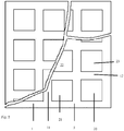
- the carbon based electrode 1 of this invention comprises a frame 10 of an electrically conductive material wherein several cut-outs 20, 21, 22, 23 are provided.
- a frame may be obtained according to various ways well known to the skilled person, for example by appropriate shaping of the electrically conductive material into a frame, by removing parts from an electrically conductive sheet of plate, or by connecting portions of electrically conductive material in such a way that a frame with several cut-outs is formed, or in any other suitable way.
- Adjacent cut-outs are separated from each other by portions 11, 12 of the conductive material.
- Portions 11, 12 may be made of the same or of a different electrically conductive material, but preferably they are made of the same electrically conductive material.
- a circumferential edge of the carbon based electrode may comprise a circumferential frame 5, which may be made of the same material as the portions 11, 12 of electrically conductive material which is preferred or frame 5 may be made of a different material.
- portions 11, 12 may be made of the same or of a different material.
- the distance between adjacent sub-electrodes is preferably kept as small as possible.
- the dimensions of the portions of the conductive material present between the cut-outs are kept as small as possible.
- the dimensions of the frame and the portions of conductive material between the cut-outs are preferably selected such that the geometric surface area occupied by them is smaller than 30 % of the total geometric surface area of the electrode, more preferably smaller than 25 %, most preferably smaller than 20 %, in particular smaller than 15% or even smaller than 10%. This will also permit increasing the portion of active electrode surface area in relation to the total surface area of the electrode.
- Electrochemical performance is understood to also refer to the potential shown by or voltage produced or voltage output or power density by the electrode at a certain current density.
- the shape of the cut-outs is not critical to the invention either and it may be selected and varied by the skilled person taking into account the shape of the frame 10 of the electrically conductive material.
- the cut-outs 20, 21, 22, 23 may be arranged within the frame 10 in a random manner, but preferably they are arranged according to a regular geometric pattern to ensure a distribution of the current over the electrode which is as homogenous as possible.
- the dimensions of the cut-outs are not critical to the invention either, in as long as they do not adversely affect the mechanical and dimensional stability of the sub-electrodes mounted therein.
- the dimensions of the cut-outs will preferably correspond to the dimensions of conventional carbon based electrodes, in particular gas diffusion carbon based electrodes, frequently used in the art.
- Suitable dimensions are, without being limited thereto, a width of about 5 to 50 cm, and a length of about 5 to 50 cm, 20X20cm being a frequently used size.
- a sub-electrode is mounted in each cut-out.
- the carbon based electrode of this invention electrode may either be an anode or a cathode, but preferably is a cathode.
- a carbon based sub-electrode suitable for mounting in the frame of electrically conductive material as described above usually comprises one or more current density distributors 8, with a layer of an electrochemically active or catalytically active material on a carbon support 3 embedded in a porous polymer matrix and arranged to one side 18 or face of the current density distributor.
- a water repellent layer 13 or hydrophobic gas diffusion outer layer may be added, which allows diffusion of reactant gasses to the catalytic reactive layer while preventing the electrolyte from leaking out of the electrolyte chamber through the electrode.
- These electrodes are tailored for use in those electrochemical cells where anode and cathode are separated by a free electrolyte liquid phase (e.g.: aqueous reaction medium, wastewater streams).
- Water Repellent Layer (WRL) or hydrophobic gas diffusion layer 2 is understood to comprise a layer of a hydrophobic material having an external surface in contact with gas and showing porosity to the gas and the ability of preventing leakage of an aqueous electrolyte into the gas diffusion layer.
- EAL Electrochemically Active Layer
- EAL is a layer in which the electrochemical reaction takes place having high electrical conductivity and porosity to gas and electrolyte and having an interface with electrolyte on one surface and a water repellant (hydrophobic gas diffusion) layer on the other.
- Either the entire face of the current density distributor 8 may be covered with the EAL and the WRL respectively or only part of it.
- the dimensions of this band 15 in width direction of the band are preferably such that a liquid tight connection to the portions of the conductive material adjacent to the sub-electrodes and the frame may be ensured in order to minimize the risk to the occurrence of cross contamination, for example leakage of reactant from one side of the electrode to the other side.
- the sub-electrodes are gas diffusion electrodes, which are typically composed of a hydrophilic catalytically active layer one side of the current density distributor and a porous hydrophobic gas diffusion layer permeable to gas and impermeable to liquid on the opposite side of the current density distributor.
- the electrodes of this invention function to separate different electrolytes from each other, at either side of the active layers of the sub-electrodes.
- a liquid tight connection between the sub-electrodes, preferably the circumferential band, and the relevant portions of electrically conductive material of the electrically conductive frame may be achieved according to various methods known to the skilled person. Particularly suitable methods include welding or soldering, as those techniques permit establishing a mechanically strong connection, with a good resistance to pressure and a minimal risk to creating a potential difference over the connection between the sub-electrodes and the portions of the electrically conductive frame.
- Other liquid tight connections may be achieved by the presence of a sealing material along the circumferential edge of the sub-electrodes, which holds the sub-electrode in the cut out in a liquid tight manner, for example a rubber gasket.
- the preferred current density distributor may take the form of a porous mesh, for example a woven, knitted or braided material, porosity being provided by the pores between the woven - knitted or braided fibers.
- the current density distributor may also take the form of a web, net, plate, sheet, foil, film or screen, with pores provided therein for example using photochemical etching or electro forming.
- the current density distributor may be made of a wide variety of electrically conductive materials, for example of metal, a metal-plastic combination, a mixed metal type, a mixture of metal and other non-metallic conductive (such as conductive polymers and conductive carbon e.g. graphite, graphene and carbon nano-tubes), and any combination thereof.
- electrically conductive material suitable for use with this invention include intrinsically conductive polymers (ICP' s), metal alloys.
- ICP' s intrinsically conductive polymers
- Preferred electrically conductive materials include stainless steel alloys, more preferably austenitic stainless steels and duplex stainless steel because of its high yield strength and stress corrosion cracking resistance to chloride, when compared to austenitic stainless steels. Austenitic stainless steels and duplex stainless steel are preferred because of their good corrosion resistance, and minimal magnetic properties.
- the carbon based electrode 1 of this invention comprises a frame 10 of an electrically conductive material wherein several cut-outs 20, 21, 22, 23 are provided. Preferably in each cut-out a carbon based sub-electrode as described above is mounted in a liquid tight manner. Thereby, all sub-electrodes may be the same. Within the scope of this invention however, sub-electrodes in different parts of the frame may be different as well. This may be of particular interest if use is made of electrochemical cells with a large volume, wherein a substantial pressure difference exists between an upper part of the cell or chamber and a lower part in the vicinity of the bottom of the cell or chamber. In the case of large volume cells, it may be preferred to provide in a lower part of the frame sub-electrodes with a smaller porosity, and to provide in an upper part of the frame sub-electrodes with a higher porosity.
- cathodes with varying dimensions (18 X 18 cm, 324 cm 2 , 0.45 mm thick) were produced using sheets manufactured by VITO (Mol, Belgium), using a proprietary process based on pressing together a mixture of AC (70-90 wt%; Norit SX plus, Norit Americas Inc., TX) and polytetrafluoroethylene (PTFE) binder, onto a stainless steel mesh current collector.
- a PTFE diffusion layer (70% porosity) was then added on top of the catalytically active layer containing the catalyst which became the air-side of the cathode.
- Sub-cathodes for small (11.3 cm 2 ) and medium (52 cm 2 ) chambers were made from portions cut from these sheets.
- a circular cathode 3.8 cm in diameter (11.2 cm 2 ) was used for the smallest reactor (0.028 liter), and a rectangular cathode of 9.2 X 5.6 cm (52 cm 2 ) was used in a medium size reactor (0.22liter).
- the large cathode (107 cm long by 64 cm in height, 0.68 m 2 ) contained 15 sub-cathodes which had been welded to one single stainless steel panel cut with 15 holes to provide the frame. The cathodes were exposed to water on one side, and air on the other side.
- the use of a single metal panel enabled obtaining a low electrical resistance of ⁇ 0.2 ⁇ between the center of each sub-cathode and any other part of the external stainless steel panel.
- Brush anodes were made with two different sizes for the different sized-chamber MFC tests.
- brushes were 2.5 cm in diameter and 2.5 cm long, and made from graphite fiber (PANEX 35 50K, Zoltek) wound between two titanium wires (Mill-Rose, Mentor, OH).
- the brushes used in the larger reactor were 5.1 cm in diameter and 61 cm long, made from the same materials as the smaller brushes (Gordon Brush, CA, USA). All anodes were heat treated at 450 °C in air for 30 min prior to use in MFCs.
- the smaller cell (SC) was a single chamber, cube-shaped reactor constructed from a polycarbonate block 4 cm in length (5 cm ⁇ 5 cm), with an inside cylindrical chamber having a diameter of 3 cm (0.028 liter total volume), and an exposed cathode area of 7 cm 2 (Table 1) that has been used in many previous MFC laboratory studies (Figure 1C).
- the cathode specific surface area was 25 m 2 m -3 -anolyte volume. Table 1.
- the medium-sized cell was a polycarbonate rectangular-shaped reactor, with an anolyte chamber 10.9 cm long, 3.5 cm wide, and 6.2 cm high, filled with 0.22 liter of electrolyte.
- the cell had a bracket slot 3.5 cm from the wall of the water side, where the cathode was attached separating the anolyte chamber from the air cathode chamber.
- the cathodes were secured to the frame with screws using a plastic U-shape fastener and a gasket (butyl rubber).
- the air chamber was 6.8 cm long, 1.0 cm wide and 4.4 cm high.
- the large cell (LC) was a specially-designed tank (1.1 m long, 0.15 m wide and 0.85 m height) that was used to examine the physical properties of the cathodes, such as mechanical strength (deformation when filled) and the resistance to water pressure (based on leaking), as well as to evaluate the electrochemical characteristics of the cathodes.
- the tank had a bracket slot 10 cm from the wall of the water side, where the cathode was attached to form the anolyte chamber.
- the cathodes were secured to the frame with screws using a plastic U-shape fastener and a gasket (Closed Cell PVC vinyl foam).
- the anolyte tank was filled with 85 liter of water, and examined by eye for deformation and water leakage when filled.
- the cathode specific surface area was 7.3 m 2 m -3 - anolyte volume. This lower specific area of the cathode permitted to accommodate the larger diameter anode brushes and provide ample room for moving the reference electrode within the chamber.
- the cathode air chamber was formed by sliding sheet of PVC into a slotted grove 5 cm from the cathode. To reduce the cathode deformation caused by water pressue, the space between the clear PVC sheet and the cathode was filled with 19 spacers 32 , constructed by rolling polypropylene mesh (XN3110-48P, Industrial Netting, USA) into tubes 4-cm diameter tubes 1 m long, with the rolled tubes held together using zip ties.
- an anode module made of polyvinyl chloride (PVC) was constructed using a linear array of graphite fiber brushes.
- the PVC module held either 8 or 22 brushes (as indicated), with the ends of the brushes secured at the top and at the bottom of the module.
- the brush modules was placed parallel to the cathode, in the middle of the anode chamber, producing a distance between the edge of the anode brushes and the cathode of 3.45 cm in initial tests.
- the anodes were connected in parallel to the circuit by an external single titanium wire.
- a clip was used to reduce the bending of the cathode sheet and to secure it in position and improving electrical connections.
- the anodes were placed horizontally in the middle of MFC chambers (perpendicular to the cathode) with a distance of 1.4 cm between the edge of the brush and the cathode.
- Electrochemical tests were performed using a potentiostat (VMP3, BioLogic, Knoxville, TN) with the cathode as the working electrode (WE), and steel mesh as the counter electrode (CE) in the medium and large chamber reactors and Pt mesh as the CE in the small chamber.
- VMP3, BioLogic, Knoxville, TN potentiostat
- CE counter electrode
- An Ag/AgCl reference electrode (RE-5B, BASi, West Lafayette, IN; + 0.209 V vs. SHE) was used in the SC and MC electrochemical tests, and placed 1.15 cm from the cathode. The ohmic losses due to the distance between the RE and the WE were corrected based on the conductivity of the solution (see information in SI and Figure S4).
- An immersion reference electrode (AGG, Electrochemical Devices Inc., OH; + 0.199 V vs. SHE) was used in the large chamber and kept close to the cathode, in the same position for all the tests. All potentials were reported versus SHE.
- the anodes in the SC reactors were fully pre-acclimated to wastewater in MFCs for over four months at a fixed external resistance of 1000 ⁇ , at a constant temperature (30 °C).
- domestic wastewater was collected once a week from the effluent of the primary clarifier at the Pennsylvania State University Waste Water Treatment Plant, and stored at 4 °C prior to use.
- Single cycle polarization tests were conducted by varying the external resistance from 1000, 500, 200, 100 and 75 at a 20 min interval after open circuiting for 2 h with a total test duration of 3.7 h, in a constant temperature room (30°C).
- the LC MFC was operated at room temperature and directly fed with fresh primary effluent wastewater.
- the feed solution was 35 L of primary effluent wastewater mixed with 40 L of 0.5 g L -1 sodium acetate in 50 mM PBS, and 10 L effluent collected over several weeks from MFCs fed acetate and wastewater.
- the external resistance was 1000 ⁇ for the first two days and then was decreased daily to 100 ⁇ , 25 ⁇ , 10 ⁇ and 5 ⁇ .
- the solution was 55 L of wastewater, 20 L of 50 mM PBS containing 0.5 g L -1 sodium acetate, and 10 L of MFC effluent.
- the LC MFC was operated using only primary effluent. After a stable cycle of voltage production for three successive fed-batch cycles, single cycle polarization tests were conducted with the LC MFC by feeding the reactor with fresh wastewater and holding the system at open circuit conditions for 2 h, and then varying the external resistance from 100, 25, 10, 5, 2, 1 to 0.4 ⁇ at a 20 min intervals.
- the current was calculated based on the voltage drop (U) across the external resistor, and recorded using a computer based data acquisition system (2700, Keithley Instrument, OH).
- anode and cathode potentials were also recorded using a reference electrode.
- An Ag/AgCl reference electrode (RE-5B, BASi, West Lafayette, IN; + 0.209 V vs.
- An immersion reference electrode (AGG, Electrochemical Devices Inc., OH; + 0.199 V vs. SHE) was used in the large chamber (LC) biotic tests to measure the cathode potential (ECt), and it was kept close to the cathode, and in the same position for all the tests.
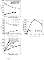
- the large cathode voltage at a current density of 0.64 A m -2 was 0.09 ⁇ 0.01 V, compared to 0.23 ⁇ 0.00 V of the medium size cathode at 0.63 ⁇ 0.00 A m -2 and 0.26 ⁇ 0.01 V at 0.62 ⁇ 0.00 A m -2 of the smaller cathode.
- Example 2 Power production of the 85 L MFC fed domestic wastewater (22 anodes).
- the slope of the trendline from the linearization of the anode potential was 0.56 ⁇ m-2 in LC biotic test, 65 % higher than the 0.34 ⁇ m -2 from the correction of the SC biotic test for the larger electrode spacing ( Figure 5D ).
- the cathode performance change of
- the anodes change of
- the reduced active area of the cathode due to the metal frame could also have been a factor in reducing anode performance, as the metal frame accounted for 23% of the exposed projected area of the cathode. Normalizing the power produced by only the active cathode area would produce a power density of 0.10 W m -2 .
- Example 3 Power production of the 85 L MFC fed domestic wastewater using 8 anodes.
- the anode potential at the maximum power density with 8 anodes was - 0.121 ⁇ 0.002 V at 0.206 ⁇ 0.006 A m -2 (normalized to the cross-sectional or projected cathode area) compared to - 0.16 ⁇ 0.01 V at the highest current density of 0.250 ⁇ 0.006 A m -2 with 22 anodes.
- maximizing full coverage of the cathodes by the anodes will permit to improve power production. 37.
- Example 4 Power production using 22 anodes.
- the MFC with 8 or 22 anodes achieved similar COD removal efficiencies of 75-80%.
- the presence of a higher number of anodes therefore did not increase the rate of COD removal, although the number of anodes did impact the amount of COD converted to electricity.
- the coulombic efficiency38 CE was 27% when using 22 anodes, but it decreased to 13% with 8 anodes.
- a cathode was manufactured to include a 316L stainless steel mesh current density distributor and an activated carbon catalyst with specifications described below:
- the cathode sheets meet the demonstration reactor dimensional requirements (1.07 m wide x 0.64 m long).
- Step 1 manufacture of 15 VITO CoRE® gas diffusion electrodes (20*20 sqcm).
- Step 2 realisation of an electrically conducting metal frame for the assembly of the electrodes using a stainless steel 316L plate from TESTAS, Belgium of 1070 x 640 mm 2 .
- the spaces for mounting the carbon based electrodes were laser cut from the metal plate, which was made of the material as the conductive current density distributor of the individual electrodes above also stainless steel 316L.
- the metal frame and the metal mesh for the current density distributor of the electrodes consist of the same metal; the thickness of the metal frame is 2,5 times the thickness of the wires forming the metal mesh.
- the conductivity of these materials was be the same, but the frame had a lower electrical resistance than the electrically conductive current density distributor present within the sub-electrodes, due to the larger thickness of the frame.
- Step 3 assembly of the Gas Diffusion Electrodes onto the metal frame
- the overall thickness of the assembly is not larger than the thickness of a single electrode.
- the welded connection between the conductive frame and the (sub)electrodes is sealed. This may be done by applying sealing material around the welding edges to ensure tightness of the assembly.
- Two component glue (MacroPlast from Loctite) was applied at the seams/jointures on the white layer side (gas feed side), it is allowed to dry for 2 days.
Landscapes
- Chemical & Material Sciences (AREA)
- Chemical Kinetics & Catalysis (AREA)
- Electrochemistry (AREA)
- General Chemical & Material Sciences (AREA)
- Electrodes For Compound Or Non-Metal Manufacture (AREA)
- Water Treatment By Electricity Or Magnetism (AREA)
Claims (15)
- Elektrode auf Kohlenstoffbasis mit einer großen geometrischen Oberfläche (mit einer Länge von wenigstens 20 cm und einer Breite von wenigstens 20 cm), umfassend einen Rahmen aus einem elektrisch leitenden Material mit mehreren Ausschnitten mit einer Oberfläche, wobei die Ausschnitte durch Abschnitte des leitenden Materials voneinander getrennt sind, wobei Unterelektroden auf Kohlenstoffbasis, die so dimensioniert sind, dass sie wenigstens die Oberfläche der Ausschnitte bedecken, in den Ausschnitten positioniert und mit wenigstens einem Teil von jedem der Abschnitte des leitenden Materials verbunden sind, das an die Unterelektroden auf Kohlenstoffbasis angrenzt.
- Elektrode auf Kohlenstoffbasis nach Anspruch 1, wobei jede der Unterelektroden einen Stromdichteverteiler enthält und wobei der Stromdichteverteiler mit wenigstens einem Teil der Abschnitte des leitenden Materials verbunden ist, das an die Unterelektrode auf Kohlenstoffbasis mit dem Stromdichteverteiler angrenzt.
- Elektrode auf Kohlenstoffbasis nach Anspruch 2, wobei der Rahmen eine elektrische Leitfähigkeit aufweist, die der elektrischen Leitfähigkeit des leitenden Stromdichteverteilers entspricht, wobei der Rahmen und der Stromdichteverteiler der Unterelektrode vorzugsweise aus dem gleichen elektrisch leitenden Material hergestellt sind.
- Elektrode auf Kohlenstoffbasis nach Anspruch 2 oder 3, wobei der Rahmen einen elektrischen Widerstand aufweist, der gleich oder kleiner als der elektrische Widerstand des Stromdichteverteilers ist.
- Elektrode auf Kohlenstoffbasis nach einem der Ansprüche 1 bis 4, wobei die Unterelektroden auf Kohlenstoffbasis wasserdicht in die Ausschnitte passen.
- Elektrode auf Kohlenstoffbasis nach Anspruch 5, wobei ein Dichtungsmaterial auf die Verbindung der Unterelektrode mit dem Rahmen aufgebracht wird.
- Elektrode auf Kohlenstoffbasis nach einem der Ansprüche 1 bis 6, wobei der Rahmen aus leitendem Material aus Metall hergestellt ist.
- Elektrode auf Kohlenstoffbasis nach einem der Ansprüche 1 bis 7, wobei die Elektrode auf Kohlenstoffbasis eine Gasdiffusionselektrode ist.
- Elektrode auf Kohlenstoffbasis nach einem der Ansprüche 1 bis 8, wobei die Abmessungen des Rahmens und die Abschnitte des leitenden Materials zwischen den Ausschnitten so ausgewählt sind, dass ihre geometrische Oberfläche höchstens 30 % der gesamten geometrischen Oberfläche der Elektrode, bevorzugter höchstens 25 %, am meisten bevorzugt höchstens 20 %, insbesondere höchstens 15 % oder sogar höchstens 10 % einnimmt.
- Elektrode auf Kohlenstoffbasis nach einem der Ansprüche 1 bis 9, wobei die Elektrode eine gesamte Oberfläche von wenigstens 400 cm2, vorzugsweise wenigstens 900 cm2, bevorzugter wenigstens 1600 cm2, am bevorzugtesten wenigstens 1000 cm2 aufweist.
- Elektrochemische Zelle, umfassend wenigstens eine Elektrode auf Kohlenstoffbasis gemäß einem der Ansprüche 1 bis 10.
- Elektrochemische Zelle nach Anspruch 11, ferner umfassend wenigstens eine Anode, wobei gegenüberliegende Seiten jeder Anode mit einer Elektrode auf Kohlenstoffbasis nach einem der Ansprüche 1 bis 10 verbunden sind.
- Elektrochemische Zelle nach Anspruch 12, wobei die Kathode eine aktive Oberfläche aufweist, die wenigstens fünfmal größer ist als die aktive Oberfläche der Anode, vorzugsweise wenigstens zehnmal.
- Elektrochemische Zelle nach einem der Ansprüche 11 bis 13, wobei Unterelektroden, die sich in einer unteren Position in der elektrochemischen Zelle näher an einem Boden der elektrochemischen Zelle befinden, eine geringere Porosität als Unterelektroden aufweisen, die sich in einer höheren Position in der elektrochemische Zelle näher an einem oberen Teil der elektrochemischen Zelle befinden.
- Elektrochemische Zelle nach einem der Ansprüche 11 bis 14, wobei die elektrochemische Zelle eine Zelle für die elektrochemische Synthese, eine elektrochemische Abwasserbehandlungszelle oder eine mikrobielle Brennstoffzelle ist.
Priority Applications (5)
| Application Number | Priority Date | Filing Date | Title |
|---|---|---|---|
| EP18176121.4A EP3579314B1 (de) | 2018-06-05 | 2018-06-05 | Kohlenstoffbasierte elektrode mit grossen geometrischen abmessungen |
| ES18176121T ES2858698T3 (es) | 2018-06-05 | 2018-06-05 | Electrodo basado en carbono con grandes dimensiones geométricas |
| US16/753,027 US11962019B2 (en) | 2017-10-03 | 2018-09-21 | Carbon based electrode with large geometric dimensions |
| CN201880064601.5A CN111758177A (zh) | 2017-10-03 | 2018-09-21 | 具有大几何尺寸的碳基电极 |
| PCT/EP2018/075646 WO2019068488A1 (en) | 2017-10-03 | 2018-09-21 | CARBON ELECTRODE HAVING LARGE GEOMETRIC DIMENSIONS |
Applications Claiming Priority (1)
| Application Number | Priority Date | Filing Date | Title |
|---|---|---|---|
| EP18176121.4A EP3579314B1 (de) | 2018-06-05 | 2018-06-05 | Kohlenstoffbasierte elektrode mit grossen geometrischen abmessungen |
Publications (2)
| Publication Number | Publication Date |
|---|---|
| EP3579314A1 EP3579314A1 (de) | 2019-12-11 |
| EP3579314B1 true EP3579314B1 (de) | 2020-12-23 |
Family
ID=62567381
Family Applications (1)
| Application Number | Title | Priority Date | Filing Date |
|---|---|---|---|
| EP18176121.4A Active EP3579314B1 (de) | 2017-10-03 | 2018-06-05 | Kohlenstoffbasierte elektrode mit grossen geometrischen abmessungen |
Country Status (2)
| Country | Link |
|---|---|
| EP (1) | EP3579314B1 (de) |
| ES (1) | ES2858698T3 (de) |
Family Cites Families (7)
| Publication number | Priority date | Publication date | Assignee | Title |
|---|---|---|---|---|
| JPS61155260A (ja) | 1984-12-27 | 1986-07-14 | 呉羽化学工業株式会社 | 炭素材同士を接合した炭素製品の製造方法 |
| EP1229149A1 (de) | 2001-01-31 | 2002-08-07 | CSEM Centre Suisse d'Electronique et de Microtechnique SA | Elektrode mit grossen Abmessungen |
| TWI317186B (en) * | 2006-08-17 | 2009-11-11 | Optodisc Technology Corp | Column type fuel cell, series device thereof and stack thereof |
| US20080297980A1 (en) * | 2007-05-31 | 2008-12-04 | Roy Joseph Bourcier | Layered carbon electrodes useful in electric double layer capacitors and capacitive deionization and methods of making the same |
| EP2770565A1 (de) | 2013-02-26 | 2014-08-27 | Vito NV | Verfahren zur Herstellung von Gasverteilungselektroden |
| US20170226647A1 (en) * | 2014-08-05 | 2017-08-10 | Vito Nv | A device and method for the production of hydrogen peroxide |
| CN108699710A (zh) * | 2015-12-14 | 2018-10-23 | 奥克海德莱克斯控股有限公司 | 高压力电化学电池 |
-
2018
- 2018-06-05 EP EP18176121.4A patent/EP3579314B1/de active Active
- 2018-06-05 ES ES18176121T patent/ES2858698T3/es active Active
Non-Patent Citations (1)
| Title |
|---|
| None * |
Also Published As
| Publication number | Publication date |
|---|---|
| ES2858698T3 (es) | 2021-09-30 |
| EP3579314A1 (de) | 2019-12-11 |
Similar Documents
| Publication | Publication Date | Title |
|---|---|---|
| CN106575776B (zh) | 与电化学电池一起使用的流场 | |
| EP2351130B1 (de) | Elektroden zur verwendung in bakteriellen kraftstoffzellen und bakteriellen elektrolysezellen sowie bakterielle kraftstoffzellen und bakterielle elektrolysezellen mit solchen elektroden | |
| US7951284B2 (en) | Electrolysis apparatus, electrochemical reaction membrane apparatus, porous electrical conductor, and production method thereof | |
| CN110199055B (zh) | 阳极、水电解用阳极、电解单元以及氢的制造方法 | |
| US8679701B2 (en) | Fuel cells | |
| JP2007242433A (ja) | 電気化学反応用電極触媒、その製造方法及び前記電極触媒を有する電気化学用電極 | |
| KR20150063347A (ko) | 가스 투과성 전극 및 전기화학적 전지 | |
| CN106133199A (zh) | 有机氢化物制造装置 | |
| JP2019119654A (ja) | 電気化学式水素ポンプ | |
| WO2008101281A1 (en) | A membrane electrode assembly with electrode support | |
| CN110402240B (zh) | 具有隔离电极的用于废水处理的电化学电池的堆叠 | |
| EP3579314B1 (de) | Kohlenstoffbasierte elektrode mit grossen geometrischen abmessungen | |
| US11962019B2 (en) | Carbon based electrode with large geometric dimensions | |
| EP1724861A1 (de) | Neue Materialien für alkalische Elektrolyseure und alkalische Brennstoffzellen | |
| JP2004300451A (ja) | ガス拡散電極、その製造方法、及び電解方法 | |
| JP3625633B2 (ja) | ガス拡散電極構造体とその製造方法 | |
| CN111463448A (zh) | 用于燃料电池和电解装置的气体分配器结构 | |
| WO2004095669A2 (en) | Clad metallic bipolar plates and electricity-producing systems and fuel cells using the same | |
| FI73008B (fi) | Elektrod till elektrolyscell av membrantyp. | |
| AU2013204526A1 (en) | Electrodes for use in bacterial fuel cells and bacterial electrolysis cells and bacterial fuel cells and bacterial electrolysis cells employing such electrodes |
Legal Events
| Date | Code | Title | Description |
|---|---|---|---|
| PUAI | Public reference made under article 153(3) epc to a published international application that has entered the european phase |
Free format text: ORIGINAL CODE: 0009012 |
|
| STAA | Information on the status of an ep patent application or granted ep patent |
Free format text: STATUS: THE APPLICATION HAS BEEN PUBLISHED |
|
| AK | Designated contracting states |
Kind code of ref document: A1 Designated state(s): AL AT BE BG CH CY CZ DE DK EE ES FI FR GB GR HR HU IE IS IT LI LT LU LV MC MK MT NL NO PL PT RO RS SE SI SK SM TR |
|
| AX | Request for extension of the european patent |
Extension state: BA ME |
|
| STAA | Information on the status of an ep patent application or granted ep patent |
Free format text: STATUS: REQUEST FOR EXAMINATION WAS MADE |
|
| 17P | Request for examination filed |
Effective date: 20200610 |
|
| RBV | Designated contracting states (corrected) |
Designated state(s): AL AT BE BG CH CY CZ DE DK EE ES FI FR GB GR HR HU IE IS IT LI LT LU LV MC MK MT NL NO PL PT RO RS SE SI SK SM TR |
|
| GRAP | Despatch of communication of intention to grant a patent |
Free format text: ORIGINAL CODE: EPIDOSNIGR1 |
|
| STAA | Information on the status of an ep patent application or granted ep patent |
Free format text: STATUS: GRANT OF PATENT IS INTENDED |
|
| INTG | Intention to grant announced |
Effective date: 20200721 |
|
| GRAS | Grant fee paid |
Free format text: ORIGINAL CODE: EPIDOSNIGR3 |
|
| GRAA | (expected) grant |
Free format text: ORIGINAL CODE: 0009210 |
|
| STAA | Information on the status of an ep patent application or granted ep patent |
Free format text: STATUS: THE PATENT HAS BEEN GRANTED |
|
| AK | Designated contracting states |
Kind code of ref document: B1 Designated state(s): AL AT BE BG CH CY CZ DE DK EE ES FI FR GB GR HR HU IE IS IT LI LT LU LV MC MK MT NL NO PL PT RO RS SE SI SK SM TR |
|
| REG | Reference to a national code |
Ref country code: GB Ref legal event code: FG4D |
|
| REG | Reference to a national code |
Ref country code: DE Ref legal event code: R096 Ref document number: 602018010997 Country of ref document: DE |
|
| REG | Reference to a national code |
Ref country code: AT Ref legal event code: REF Ref document number: 1348599 Country of ref document: AT Kind code of ref document: T Effective date: 20210115 |
|
| REG | Reference to a national code |
Ref country code: IE Ref legal event code: FG4D |
|
| REG | Reference to a national code |
Ref country code: NL Ref legal event code: FP |
|
| PG25 | Lapsed in a contracting state [announced via postgrant information from national office to epo] |
Ref country code: FI Free format text: LAPSE BECAUSE OF FAILURE TO SUBMIT A TRANSLATION OF THE DESCRIPTION OR TO PAY THE FEE WITHIN THE PRESCRIBED TIME-LIMIT Effective date: 20201223 Ref country code: RS Free format text: LAPSE BECAUSE OF FAILURE TO SUBMIT A TRANSLATION OF THE DESCRIPTION OR TO PAY THE FEE WITHIN THE PRESCRIBED TIME-LIMIT Effective date: 20201223 Ref country code: GR Free format text: LAPSE BECAUSE OF FAILURE TO SUBMIT A TRANSLATION OF THE DESCRIPTION OR TO PAY THE FEE WITHIN THE PRESCRIBED TIME-LIMIT Effective date: 20210324 Ref country code: NO Free format text: LAPSE BECAUSE OF FAILURE TO SUBMIT A TRANSLATION OF THE DESCRIPTION OR TO PAY THE FEE WITHIN THE PRESCRIBED TIME-LIMIT Effective date: 20210323 |
|
| REG | Reference to a national code |
Ref country code: AT Ref legal event code: MK05 Ref document number: 1348599 Country of ref document: AT Kind code of ref document: T Effective date: 20201223 |
|
| PG25 | Lapsed in a contracting state [announced via postgrant information from national office to epo] |
Ref country code: BG Free format text: LAPSE BECAUSE OF FAILURE TO SUBMIT A TRANSLATION OF THE DESCRIPTION OR TO PAY THE FEE WITHIN THE PRESCRIBED TIME-LIMIT Effective date: 20210323 Ref country code: LV Free format text: LAPSE BECAUSE OF FAILURE TO SUBMIT A TRANSLATION OF THE DESCRIPTION OR TO PAY THE FEE WITHIN THE PRESCRIBED TIME-LIMIT Effective date: 20201223 Ref country code: SE Free format text: LAPSE BECAUSE OF FAILURE TO SUBMIT A TRANSLATION OF THE DESCRIPTION OR TO PAY THE FEE WITHIN THE PRESCRIBED TIME-LIMIT Effective date: 20201223 |
|
| PG25 | Lapsed in a contracting state [announced via postgrant information from national office to epo] |
Ref country code: HR Free format text: LAPSE BECAUSE OF FAILURE TO SUBMIT A TRANSLATION OF THE DESCRIPTION OR TO PAY THE FEE WITHIN THE PRESCRIBED TIME-LIMIT Effective date: 20201223 |
|
| REG | Reference to a national code |
Ref country code: LT Ref legal event code: MG9D |
|
| PG25 | Lapsed in a contracting state [announced via postgrant information from national office to epo] |
Ref country code: SM Free format text: LAPSE BECAUSE OF FAILURE TO SUBMIT A TRANSLATION OF THE DESCRIPTION OR TO PAY THE FEE WITHIN THE PRESCRIBED TIME-LIMIT Effective date: 20201223 Ref country code: CZ Free format text: LAPSE BECAUSE OF FAILURE TO SUBMIT A TRANSLATION OF THE DESCRIPTION OR TO PAY THE FEE WITHIN THE PRESCRIBED TIME-LIMIT Effective date: 20201223 Ref country code: EE Free format text: LAPSE BECAUSE OF FAILURE TO SUBMIT A TRANSLATION OF THE DESCRIPTION OR TO PAY THE FEE WITHIN THE PRESCRIBED TIME-LIMIT Effective date: 20201223 Ref country code: RO Free format text: LAPSE BECAUSE OF FAILURE TO SUBMIT A TRANSLATION OF THE DESCRIPTION OR TO PAY THE FEE WITHIN THE PRESCRIBED TIME-LIMIT Effective date: 20201223 Ref country code: PT Free format text: LAPSE BECAUSE OF FAILURE TO SUBMIT A TRANSLATION OF THE DESCRIPTION OR TO PAY THE FEE WITHIN THE PRESCRIBED TIME-LIMIT Effective date: 20210423 Ref country code: SK Free format text: LAPSE BECAUSE OF FAILURE TO SUBMIT A TRANSLATION OF THE DESCRIPTION OR TO PAY THE FEE WITHIN THE PRESCRIBED TIME-LIMIT Effective date: 20201223 Ref country code: LT Free format text: LAPSE BECAUSE OF FAILURE TO SUBMIT A TRANSLATION OF THE DESCRIPTION OR TO PAY THE FEE WITHIN THE PRESCRIBED TIME-LIMIT Effective date: 20201223 |
|
| PG25 | Lapsed in a contracting state [announced via postgrant information from national office to epo] |
Ref country code: AT Free format text: LAPSE BECAUSE OF FAILURE TO SUBMIT A TRANSLATION OF THE DESCRIPTION OR TO PAY THE FEE WITHIN THE PRESCRIBED TIME-LIMIT Effective date: 20201223 Ref country code: PL Free format text: LAPSE BECAUSE OF FAILURE TO SUBMIT A TRANSLATION OF THE DESCRIPTION OR TO PAY THE FEE WITHIN THE PRESCRIBED TIME-LIMIT Effective date: 20201223 |
|
| REG | Reference to a national code |
Ref country code: DE Ref legal event code: R097 Ref document number: 602018010997 Country of ref document: DE |
|
| PG25 | Lapsed in a contracting state [announced via postgrant information from national office to epo] |
Ref country code: IS Free format text: LAPSE BECAUSE OF FAILURE TO SUBMIT A TRANSLATION OF THE DESCRIPTION OR TO PAY THE FEE WITHIN THE PRESCRIBED TIME-LIMIT Effective date: 20210423 |
|
| REG | Reference to a national code |
Ref country code: ES Ref legal event code: FG2A Ref document number: 2858698 Country of ref document: ES Kind code of ref document: T3 Effective date: 20210930 |
|
| PG25 | Lapsed in a contracting state [announced via postgrant information from national office to epo] |
Ref country code: AL Free format text: LAPSE BECAUSE OF FAILURE TO SUBMIT A TRANSLATION OF THE DESCRIPTION OR TO PAY THE FEE WITHIN THE PRESCRIBED TIME-LIMIT Effective date: 20201223 |
|
| PLBE | No opposition filed within time limit |
Free format text: ORIGINAL CODE: 0009261 |
|
| STAA | Information on the status of an ep patent application or granted ep patent |
Free format text: STATUS: NO OPPOSITION FILED WITHIN TIME LIMIT |
|
| PG25 | Lapsed in a contracting state [announced via postgrant information from national office to epo] |
Ref country code: DK Free format text: LAPSE BECAUSE OF FAILURE TO SUBMIT A TRANSLATION OF THE DESCRIPTION OR TO PAY THE FEE WITHIN THE PRESCRIBED TIME-LIMIT Effective date: 20201223 |
|
| 26N | No opposition filed |
Effective date: 20210924 |
|
| PG25 | Lapsed in a contracting state [announced via postgrant information from national office to epo] |
Ref country code: MC Free format text: LAPSE BECAUSE OF FAILURE TO SUBMIT A TRANSLATION OF THE DESCRIPTION OR TO PAY THE FEE WITHIN THE PRESCRIBED TIME-LIMIT Effective date: 20201223 |
|
| REG | Reference to a national code |
Ref country code: CH Ref legal event code: PL |
|
| PG25 | Lapsed in a contracting state [announced via postgrant information from national office to epo] |
Ref country code: SI Free format text: LAPSE BECAUSE OF FAILURE TO SUBMIT A TRANSLATION OF THE DESCRIPTION OR TO PAY THE FEE WITHIN THE PRESCRIBED TIME-LIMIT Effective date: 20201223 |
|
| PG25 | Lapsed in a contracting state [announced via postgrant information from national office to epo] |
Ref country code: LI Free format text: LAPSE BECAUSE OF NON-PAYMENT OF DUE FEES Effective date: 20210630 Ref country code: IE Free format text: LAPSE BECAUSE OF NON-PAYMENT OF DUE FEES Effective date: 20210605 Ref country code: CH Free format text: LAPSE BECAUSE OF NON-PAYMENT OF DUE FEES Effective date: 20210630 |
|
| PG25 | Lapsed in a contracting state [announced via postgrant information from national office to epo] |
Ref country code: IS Free format text: LAPSE BECAUSE OF FAILURE TO SUBMIT A TRANSLATION OF THE DESCRIPTION OR TO PAY THE FEE WITHIN THE PRESCRIBED TIME-LIMIT Effective date: 20210423 |
|
| PG25 | Lapsed in a contracting state [announced via postgrant information from national office to epo] |
Ref country code: CY Free format text: LAPSE BECAUSE OF FAILURE TO SUBMIT A TRANSLATION OF THE DESCRIPTION OR TO PAY THE FEE WITHIN THE PRESCRIBED TIME-LIMIT Effective date: 20201223 |
|
| P01 | Opt-out of the competence of the unified patent court (upc) registered |
Effective date: 20230528 |
|
| PG25 | Lapsed in a contracting state [announced via postgrant information from national office to epo] |
Ref country code: HU Free format text: LAPSE BECAUSE OF FAILURE TO SUBMIT A TRANSLATION OF THE DESCRIPTION OR TO PAY THE FEE WITHIN THE PRESCRIBED TIME-LIMIT; INVALID AB INITIO Effective date: 20180605 |
|
| PGFP | Annual fee paid to national office [announced via postgrant information from national office to epo] |
Ref country code: ES Payment date: 20230703 Year of fee payment: 6 |
|
| PG25 | Lapsed in a contracting state [announced via postgrant information from national office to epo] |
Ref country code: MK Free format text: LAPSE BECAUSE OF FAILURE TO SUBMIT A TRANSLATION OF THE DESCRIPTION OR TO PAY THE FEE WITHIN THE PRESCRIBED TIME-LIMIT Effective date: 20201223 |
|
| PGFP | Annual fee paid to national office [announced via postgrant information from national office to epo] |
Ref country code: LU Payment date: 20240521 Year of fee payment: 7 |
|
| PGFP | Annual fee paid to national office [announced via postgrant information from national office to epo] |
Ref country code: NL Payment date: 20240521 Year of fee payment: 7 |
|
| PG25 | Lapsed in a contracting state [announced via postgrant information from national office to epo] |
Ref country code: TR Free format text: LAPSE BECAUSE OF FAILURE TO SUBMIT A TRANSLATION OF THE DESCRIPTION OR TO PAY THE FEE WITHIN THE PRESCRIBED TIME-LIMIT Effective date: 20201223 |
|
| PGFP | Annual fee paid to national office [announced via postgrant information from national office to epo] |
Ref country code: GB Payment date: 20240521 Year of fee payment: 7 |
|
| PGFP | Annual fee paid to national office [announced via postgrant information from national office to epo] |
Ref country code: DE Payment date: 20240521 Year of fee payment: 7 |
|
| PGFP | Annual fee paid to national office [announced via postgrant information from national office to epo] |
Ref country code: IT Payment date: 20240522 Year of fee payment: 7 Ref country code: FR Payment date: 20240522 Year of fee payment: 7 |
|
| PGFP | Annual fee paid to national office [announced via postgrant information from national office to epo] |
Ref country code: BE Payment date: 20240521 Year of fee payment: 7 |
|
| PG25 | Lapsed in a contracting state [announced via postgrant information from national office to epo] |
Ref country code: MT Free format text: LAPSE BECAUSE OF FAILURE TO SUBMIT A TRANSLATION OF THE DESCRIPTION OR TO PAY THE FEE WITHIN THE PRESCRIBED TIME-LIMIT Effective date: 20201223 |