EP3576922B1 - Verfahren und vorrichtung zur herstellung von schaum-verbundelementen - Google Patents
Verfahren und vorrichtung zur herstellung von schaum-verbundelementen Download PDFInfo
- Publication number
- EP3576922B1 EP3576922B1 EP18701201.8A EP18701201A EP3576922B1 EP 3576922 B1 EP3576922 B1 EP 3576922B1 EP 18701201 A EP18701201 A EP 18701201A EP 3576922 B1 EP3576922 B1 EP 3576922B1
- Authority
- EP
- European Patent Office
- Prior art keywords
- distributor
- reaction mixture
- rake
- discharge
- mixing
- Prior art date
- Legal status (The legal status is an assumption and is not a legal conclusion. Google has not performed a legal analysis and makes no representation as to the accuracy of the status listed.)
- Active
Links
- 238000000034 method Methods 0.000 title claims description 30
- 239000002131 composite material Substances 0.000 title description 23
- 239000006260 foam Substances 0.000 title description 20
- 239000011541 reaction mixture Substances 0.000 claims description 71
- 229920005862 polyol Polymers 0.000 claims description 26
- 150000003077 polyols Chemical class 0.000 claims description 25
- 239000000203 mixture Substances 0.000 claims description 16
- 239000004604 Blowing Agent Substances 0.000 claims description 15
- 239000000463 material Substances 0.000 claims description 14
- 239000005056 polyisocyanate Substances 0.000 claims description 7
- 229920001228 polyisocyanate Polymers 0.000 claims description 7
- 239000000376 reactant Substances 0.000 claims description 4
- 238000005266 casting Methods 0.000 description 57
- 239000010410 layer Substances 0.000 description 53
- 239000000047 product Substances 0.000 description 47
- 238000004519 manufacturing process Methods 0.000 description 20
- LYCAIKOWRPUZTN-UHFFFAOYSA-N Ethylene glycol Chemical compound OCCO LYCAIKOWRPUZTN-UHFFFAOYSA-N 0.000 description 13
- -1 ester polyols Chemical class 0.000 description 13
- 239000003054 catalyst Substances 0.000 description 12
- 238000005187 foaming Methods 0.000 description 11
- 238000009413 insulation Methods 0.000 description 11
- MTHSVFCYNBDYFN-UHFFFAOYSA-N diethylene glycol Chemical compound OCCOCCO MTHSVFCYNBDYFN-UHFFFAOYSA-N 0.000 description 9
- 239000003380 propellant Substances 0.000 description 9
- 150000001875 compounds Chemical class 0.000 description 8
- 125000002496 methyl group Chemical group [H]C([H])([H])* 0.000 description 8
- 125000004432 carbon atom Chemical group C* 0.000 description 7
- 238000006243 chemical reaction Methods 0.000 description 7
- 150000002009 diols Chemical class 0.000 description 7
- PEDCQBHIVMGVHV-UHFFFAOYSA-N Glycerine Chemical compound OCC(O)CO PEDCQBHIVMGVHV-UHFFFAOYSA-N 0.000 description 6
- OFOBLEOULBTSOW-UHFFFAOYSA-N Propanedioic acid Natural products OC(=O)CC(O)=O OFOBLEOULBTSOW-UHFFFAOYSA-N 0.000 description 6
- ZMANZCXQSJIPKH-UHFFFAOYSA-N Triethylamine Chemical compound CCN(CC)CC ZMANZCXQSJIPKH-UHFFFAOYSA-N 0.000 description 6
- 239000002253 acid Substances 0.000 description 6
- 229910052782 aluminium Inorganic materials 0.000 description 6
- XAGFODPZIPBFFR-UHFFFAOYSA-N aluminium Chemical compound [Al] XAGFODPZIPBFFR-UHFFFAOYSA-N 0.000 description 6
- WERYXYBDKMZEQL-UHFFFAOYSA-N butane-1,4-diol Chemical compound OCCCCO WERYXYBDKMZEQL-UHFFFAOYSA-N 0.000 description 6
- 239000012948 isocyanate Substances 0.000 description 6
- 150000002513 isocyanates Chemical class 0.000 description 6
- XNGIFLGASWRNHJ-UHFFFAOYSA-N phthalic acid Chemical compound OC(=O)C1=CC=CC=C1C(O)=O XNGIFLGASWRNHJ-UHFFFAOYSA-N 0.000 description 6
- 239000004417 polycarbonate Substances 0.000 description 6
- 229920000515 polycarbonate Polymers 0.000 description 6
- 229920000570 polyether Polymers 0.000 description 6
- SCVFZCLFOSHCOH-UHFFFAOYSA-M potassium acetate Chemical compound [K+].CC([O-])=O SCVFZCLFOSHCOH-UHFFFAOYSA-M 0.000 description 6
- PUPZLCDOIYMWBV-UHFFFAOYSA-N (+/-)-1,3-Butanediol Chemical compound CC(O)CCO PUPZLCDOIYMWBV-UHFFFAOYSA-N 0.000 description 5
- SVYKKECYCPFKGB-UHFFFAOYSA-N N,N-dimethylcyclohexylamine Chemical compound CN(C)C1CCCCC1 SVYKKECYCPFKGB-UHFFFAOYSA-N 0.000 description 5
- OFBQJSOFQDEBGM-UHFFFAOYSA-N Pentane Chemical compound CCCCC OFBQJSOFQDEBGM-UHFFFAOYSA-N 0.000 description 5
- 239000004721 Polyphenylene oxide Substances 0.000 description 5
- 239000000654 additive Substances 0.000 description 5
- 238000009826 distribution Methods 0.000 description 5
- 238000005516 engineering process Methods 0.000 description 5
- CXMXRPHRNRROMY-UHFFFAOYSA-N sebacic acid Chemical compound OC(=O)CCCCCCCCC(O)=O CXMXRPHRNRROMY-UHFFFAOYSA-N 0.000 description 5
- GTEXIOINCJRBIO-UHFFFAOYSA-N 2-[2-(dimethylamino)ethoxy]-n,n-dimethylethanamine Chemical compound CN(C)CCOCCN(C)C GTEXIOINCJRBIO-UHFFFAOYSA-N 0.000 description 4
- RGSFGYAAUTVSQA-UHFFFAOYSA-N Cyclopentane Chemical compound C1CCCC1 RGSFGYAAUTVSQA-UHFFFAOYSA-N 0.000 description 4
- VZCYOOQTPOCHFL-OWOJBTEDSA-N Fumaric acid Chemical compound OC(=O)\C=C\C(O)=O VZCYOOQTPOCHFL-OWOJBTEDSA-N 0.000 description 4
- DNIAPMSPPWPWGF-UHFFFAOYSA-N Propylene glycol Chemical compound CC(O)CO DNIAPMSPPWPWGF-UHFFFAOYSA-N 0.000 description 4
- KKEYFWRCBNTPAC-UHFFFAOYSA-N Terephthalic acid Chemical compound OC(=O)C1=CC=C(C(O)=O)C=C1 KKEYFWRCBNTPAC-UHFFFAOYSA-N 0.000 description 4
- WNLRTRBMVRJNCN-UHFFFAOYSA-N adipic acid Chemical compound OC(=O)CCCCC(O)=O WNLRTRBMVRJNCN-UHFFFAOYSA-N 0.000 description 4
- 229930195733 hydrocarbon Natural products 0.000 description 4
- 150000002430 hydrocarbons Chemical class 0.000 description 4
- BDJRBEYXGGNYIS-UHFFFAOYSA-N nonanedioic acid Chemical compound OC(=O)CCCCCCCC(O)=O BDJRBEYXGGNYIS-UHFFFAOYSA-N 0.000 description 4
- 239000000123 paper Substances 0.000 description 4
- UKODFQOELJFMII-UHFFFAOYSA-N pentamethyldiethylenetriamine Chemical compound CN(C)CCN(C)CCN(C)C UKODFQOELJFMII-UHFFFAOYSA-N 0.000 description 4
- ZUFQCVZBBNZMKD-UHFFFAOYSA-M potassium 2-ethylhexanoate Chemical compound [K+].CCCCC(CC)C([O-])=O ZUFQCVZBBNZMKD-UHFFFAOYSA-M 0.000 description 4
- 230000009257 reactivity Effects 0.000 description 4
- VZCYOOQTPOCHFL-UHFFFAOYSA-N trans-butenedioic acid Natural products OC(=O)C=CC(O)=O VZCYOOQTPOCHFL-UHFFFAOYSA-N 0.000 description 4
- UPMLOUAZCHDJJD-UHFFFAOYSA-N 4,4'-Diphenylmethane Diisocyanate Chemical compound C1=CC(N=C=O)=CC=C1CC1=CC=C(N=C=O)C=C1 UPMLOUAZCHDJJD-UHFFFAOYSA-N 0.000 description 3
- WYURNTSHIVDZCO-UHFFFAOYSA-N Tetrahydrofuran Chemical compound C1CCOC1 WYURNTSHIVDZCO-UHFFFAOYSA-N 0.000 description 3
- GSEJCLTVZPLZKY-UHFFFAOYSA-N Triethanolamine Chemical compound OCCN(CCO)CCO GSEJCLTVZPLZKY-UHFFFAOYSA-N 0.000 description 3
- 150000007513 acids Chemical class 0.000 description 3
- 150000001336 alkenes Chemical class 0.000 description 3
- KRKNYBCHXYNGOX-UHFFFAOYSA-N citric acid Chemical compound OC(=O)CC(O)(C(O)=O)CC(O)=O KRKNYBCHXYNGOX-UHFFFAOYSA-N 0.000 description 3
- 150000002148 esters Chemical class 0.000 description 3
- 150000002170 ethers Chemical class 0.000 description 3
- 239000011888 foil Substances 0.000 description 3
- ZZUFCTLCJUWOSV-UHFFFAOYSA-N furosemide Chemical compound C1=C(Cl)C(S(=O)(=O)N)=CC(C(O)=O)=C1NCC1=CC=CO1 ZZUFCTLCJUWOSV-UHFFFAOYSA-N 0.000 description 3
- XXMIOPMDWAUFGU-UHFFFAOYSA-N hexane-1,6-diol Chemical compound OCCCCCCO XXMIOPMDWAUFGU-UHFFFAOYSA-N 0.000 description 3
- 125000002887 hydroxy group Chemical group [H]O* 0.000 description 3
- ZFSLODLOARCGLH-UHFFFAOYSA-N isocyanuric acid Chemical compound OC1=NC(O)=NC(O)=N1 ZFSLODLOARCGLH-UHFFFAOYSA-N 0.000 description 3
- QQVIHTHCMHWDBS-UHFFFAOYSA-N isophthalic acid Chemical compound OC(=O)C1=CC=CC(C(O)=O)=C1 QQVIHTHCMHWDBS-UHFFFAOYSA-N 0.000 description 3
- 229910052751 metal Inorganic materials 0.000 description 3
- 239000002184 metal Substances 0.000 description 3
- 229920005906 polyester polyol Polymers 0.000 description 3
- 229920000582 polyisocyanurate Polymers 0.000 description 3
- 239000011495 polyisocyanurate Substances 0.000 description 3
- 239000004814 polyurethane Substances 0.000 description 3
- 229920002635 polyurethane Polymers 0.000 description 3
- 235000011056 potassium acetate Nutrition 0.000 description 3
- DNIAPMSPPWPWGF-VKHMYHEASA-N (+)-propylene glycol Chemical compound C[C@H](O)CO DNIAPMSPPWPWGF-VKHMYHEASA-N 0.000 description 2
- LDTMPQQAWUMPKS-OWOJBTEDSA-N (e)-1-chloro-3,3,3-trifluoroprop-1-ene Chemical compound FC(F)(F)\C=C\Cl LDTMPQQAWUMPKS-OWOJBTEDSA-N 0.000 description 2
- GIWQSPITLQVMSG-UHFFFAOYSA-N 1,2-dimethylimidazole Chemical compound CC1=NC=CN1C GIWQSPITLQVMSG-UHFFFAOYSA-N 0.000 description 2
- YPFDHNVEDLHUCE-UHFFFAOYSA-N 1,3-propanediol Substances OCCCO YPFDHNVEDLHUCE-UHFFFAOYSA-N 0.000 description 2
- RXYPXQSKLGGKOL-UHFFFAOYSA-N 1,4-dimethylpiperazine Chemical compound CN1CCN(C)CC1 RXYPXQSKLGGKOL-UHFFFAOYSA-N 0.000 description 2
- OMDXZWUHIHTREC-UHFFFAOYSA-N 1-[2-(dimethylamino)ethoxy]ethanol Chemical compound CC(O)OCCN(C)C OMDXZWUHIHTREC-UHFFFAOYSA-N 0.000 description 2
- RTBFRGCFXZNCOE-UHFFFAOYSA-N 1-methylsulfonylpiperidin-4-one Chemical compound CS(=O)(=O)N1CCC(=O)CC1 RTBFRGCFXZNCOE-UHFFFAOYSA-N 0.000 description 2
- AHDSRXYHVZECER-UHFFFAOYSA-N 2,4,6-tris[(dimethylamino)methyl]phenol Chemical compound CN(C)CC1=CC(CN(C)C)=C(O)C(CN(C)C)=C1 AHDSRXYHVZECER-UHFFFAOYSA-N 0.000 description 2
- LSYBWANTZYUTGJ-UHFFFAOYSA-N 2-[2-(dimethylamino)ethyl-methylamino]ethanol Chemical compound CN(C)CCN(C)CCO LSYBWANTZYUTGJ-UHFFFAOYSA-N 0.000 description 2
- GHPVDCPCKSNJDR-UHFFFAOYSA-N 2-hydroxydecanoic acid Chemical compound CCCCCCCCC(O)C(O)=O GHPVDCPCKSNJDR-UHFFFAOYSA-N 0.000 description 2
- WAPWXMDDHHWKNM-UHFFFAOYSA-N 3-[2,3-bis[3-(dimethylamino)propyl]triazinan-1-yl]-n,n-dimethylpropan-1-amine Chemical compound CN(C)CCCN1CCCN(CCCN(C)C)N1CCCN(C)C WAPWXMDDHHWKNM-UHFFFAOYSA-N 0.000 description 2
- YEJRWHAVMIAJKC-UHFFFAOYSA-N 4-Butyrolactone Chemical compound O=C1CCCO1 YEJRWHAVMIAJKC-UHFFFAOYSA-N 0.000 description 2
- CURLTUGMZLYLDI-UHFFFAOYSA-N Carbon dioxide Chemical compound O=C=O CURLTUGMZLYLDI-UHFFFAOYSA-N 0.000 description 2
- JOYRKODLDBILNP-UHFFFAOYSA-N Ethyl urethane Chemical compound CCOC(N)=O JOYRKODLDBILNP-UHFFFAOYSA-N 0.000 description 2
- IAYPIBMASNFSPL-UHFFFAOYSA-N Ethylene oxide Chemical compound C1CO1 IAYPIBMASNFSPL-UHFFFAOYSA-N 0.000 description 2
- KWYHDKDOAIKMQN-UHFFFAOYSA-N N,N,N',N'-tetramethylethylenediamine Chemical compound CN(C)CCN(C)C KWYHDKDOAIKMQN-UHFFFAOYSA-N 0.000 description 2
- UEEJHVSXFDXPFK-UHFFFAOYSA-N N-dimethylaminoethanol Chemical compound CN(C)CCO UEEJHVSXFDXPFK-UHFFFAOYSA-N 0.000 description 2
- AKNUHUCEWALCOI-UHFFFAOYSA-N N-ethyldiethanolamine Chemical compound OCCN(CC)CCO AKNUHUCEWALCOI-UHFFFAOYSA-N 0.000 description 2
- GOOHAUXETOMSMM-UHFFFAOYSA-N Propylene oxide Chemical compound CC1CO1 GOOHAUXETOMSMM-UHFFFAOYSA-N 0.000 description 2
- 229910000831 Steel Inorganic materials 0.000 description 2
- SLINHMUFWFWBMU-UHFFFAOYSA-N Triisopropanolamine Chemical compound CC(O)CN(CC(C)O)CC(C)O SLINHMUFWFWBMU-UHFFFAOYSA-N 0.000 description 2
- ZJCCRDAZUWHFQH-UHFFFAOYSA-N Trimethylolpropane Chemical compound CCC(CO)(CO)CO ZJCCRDAZUWHFQH-UHFFFAOYSA-N 0.000 description 2
- 239000001361 adipic acid Substances 0.000 description 2
- 235000011037 adipic acid Nutrition 0.000 description 2
- 150000001298 alcohols Chemical class 0.000 description 2
- 229910052784 alkaline earth metal Inorganic materials 0.000 description 2
- 150000008064 anhydrides Chemical class 0.000 description 2
- JFCQEDHGNNZCLN-UHFFFAOYSA-N anhydrous glutaric acid Natural products OC(=O)CCCC(O)=O JFCQEDHGNNZCLN-UHFFFAOYSA-N 0.000 description 2
- 230000001174 ascending effect Effects 0.000 description 2
- WPYMKLBDIGXBTP-UHFFFAOYSA-N benzoic acid Chemical compound OC(=O)C1=CC=CC=C1 WPYMKLBDIGXBTP-UHFFFAOYSA-N 0.000 description 2
- IISBACLAFKSPIT-UHFFFAOYSA-N bisphenol A Chemical compound C=1C=C(O)C=CC=1C(C)(C)C1=CC=C(O)C=C1 IISBACLAFKSPIT-UHFFFAOYSA-N 0.000 description 2
- BVKZGUZCCUSVTD-UHFFFAOYSA-N carbonic acid Chemical class OC(O)=O BVKZGUZCCUSVTD-UHFFFAOYSA-N 0.000 description 2
- 150000007942 carboxylates Chemical class 0.000 description 2
- 239000002666 chemical blowing agent Substances 0.000 description 2
- 229960002887 deanol Drugs 0.000 description 2
- 150000001991 dicarboxylic acids Chemical class 0.000 description 2
- 235000014113 dietary fatty acids Nutrition 0.000 description 2
- 125000005442 diisocyanate group Chemical group 0.000 description 2
- XXBDWLFCJWSEKW-UHFFFAOYSA-N dimethylbenzylamine Chemical compound CN(C)CC1=CC=CC=C1 XXBDWLFCJWSEKW-UHFFFAOYSA-N 0.000 description 2
- 239000012972 dimethylethanolamine Substances 0.000 description 2
- 239000012971 dimethylpiperazine Substances 0.000 description 2
- SHZIWNPUGXLXDT-UHFFFAOYSA-N ethyl hexanoate Chemical compound CCCCCC(=O)OCC SHZIWNPUGXLXDT-UHFFFAOYSA-N 0.000 description 2
- 229930195729 fatty acid Natural products 0.000 description 2
- 239000000194 fatty acid Substances 0.000 description 2
- 150000004665 fatty acids Chemical class 0.000 description 2
- 239000001530 fumaric acid Substances 0.000 description 2
- DMEGYFMYUHOHGS-UHFFFAOYSA-N heptamethylene Natural products C1CCCCCC1 DMEGYFMYUHOHGS-UHFFFAOYSA-N 0.000 description 2
- MNWFXJYAOYHMED-UHFFFAOYSA-N hexane carboxylic acid Natural products CCCCCCC(O)=O MNWFXJYAOYHMED-UHFFFAOYSA-N 0.000 description 2
- WGCNASOHLSPBMP-UHFFFAOYSA-N hydroxyacetaldehyde Natural products OCC=O WGCNASOHLSPBMP-UHFFFAOYSA-N 0.000 description 2
- 239000011261 inert gas Substances 0.000 description 2
- NNPPMTNAJDCUHE-UHFFFAOYSA-N isobutane Chemical compound CC(C)C NNPPMTNAJDCUHE-UHFFFAOYSA-N 0.000 description 2
- QWTDNUCVQCZILF-UHFFFAOYSA-N isopentane Chemical compound CCC(C)C QWTDNUCVQCZILF-UHFFFAOYSA-N 0.000 description 2
- LVHBHZANLOWSRM-UHFFFAOYSA-N itaconic acid Chemical compound OC(=O)CC(=C)C(O)=O LVHBHZANLOWSRM-UHFFFAOYSA-N 0.000 description 2
- 150000002596 lactones Chemical class 0.000 description 2
- VZCYOOQTPOCHFL-UPHRSURJSA-N maleic acid Chemical compound OC(=O)\C=C/C(O)=O VZCYOOQTPOCHFL-UPHRSURJSA-N 0.000 description 2
- 239000011976 maleic acid Substances 0.000 description 2
- BDAGIHXWWSANSR-UHFFFAOYSA-N methanoic acid Natural products OC=O BDAGIHXWWSANSR-UHFFFAOYSA-N 0.000 description 2
- CRVGTESFCCXCTH-UHFFFAOYSA-N methyl diethanolamine Chemical group OCCN(C)CCO CRVGTESFCCXCTH-UHFFFAOYSA-N 0.000 description 2
- SLCVBVWXLSEKPL-UHFFFAOYSA-N neopentyl glycol Chemical compound OCC(C)(C)CO SLCVBVWXLSEKPL-UHFFFAOYSA-N 0.000 description 2
- WXZMFSXDPGVJKK-UHFFFAOYSA-N pentaerythritol Chemical compound OCC(CO)(CO)CO WXZMFSXDPGVJKK-UHFFFAOYSA-N 0.000 description 2
- MSSNHSVIGIHOJA-UHFFFAOYSA-N pentafluoropropane Chemical compound FC(F)CC(F)(F)F MSSNHSVIGIHOJA-UHFFFAOYSA-N 0.000 description 2
- WLJVNTCWHIRURA-UHFFFAOYSA-N pimelic acid Chemical compound OC(=O)CCCCCC(O)=O WLJVNTCWHIRURA-UHFFFAOYSA-N 0.000 description 2
- 239000002985 plastic film Substances 0.000 description 2
- 229920006255 plastic film Polymers 0.000 description 2
- 229920000728 polyester Polymers 0.000 description 2
- 229920000166 polytrimethylene carbonate Polymers 0.000 description 2
- 235000013772 propylene glycol Nutrition 0.000 description 2
- 239000002994 raw material Substances 0.000 description 2
- 229910001220 stainless steel Inorganic materials 0.000 description 2
- 239000010935 stainless steel Substances 0.000 description 2
- 239000007858 starting material Substances 0.000 description 2
- 239000010959 steel Substances 0.000 description 2
- TYFQFVWCELRYAO-UHFFFAOYSA-N suberic acid Chemical compound OC(=O)CCCCCCC(O)=O TYFQFVWCELRYAO-UHFFFAOYSA-N 0.000 description 2
- 150000003512 tertiary amines Chemical class 0.000 description 2
- IMFACGCPASFAPR-UHFFFAOYSA-N tributylamine Chemical compound CCCCN(CCCC)CCCC IMFACGCPASFAPR-UHFFFAOYSA-N 0.000 description 2
- ARCGXLSVLAOJQL-UHFFFAOYSA-N trimellitic acid Chemical compound OC(=O)C1=CC=C(C(O)=O)C(C(O)=O)=C1 ARCGXLSVLAOJQL-UHFFFAOYSA-N 0.000 description 2
- 238000005829 trimerization reaction Methods 0.000 description 2
- NIDNOXCRFUCAKQ-UMRXKNAASA-N (1s,2r,3s,4r)-bicyclo[2.2.1]hept-5-ene-2,3-dicarboxylic acid Chemical compound C1[C@H]2C=C[C@@H]1[C@H](C(=O)O)[C@@H]2C(O)=O NIDNOXCRFUCAKQ-UMRXKNAASA-N 0.000 description 1
- SZCWBURCISJFEZ-UHFFFAOYSA-N (3-hydroxy-2,2-dimethylpropyl) 3-hydroxy-2,2-dimethylpropanoate Chemical compound OCC(C)(C)COC(=O)C(C)(C)CO SZCWBURCISJFEZ-UHFFFAOYSA-N 0.000 description 1
- 125000004169 (C1-C6) alkyl group Chemical group 0.000 description 1
- DNIAPMSPPWPWGF-GSVOUGTGSA-N (R)-(-)-Propylene glycol Chemical compound C[C@@H](O)CO DNIAPMSPPWPWGF-GSVOUGTGSA-N 0.000 description 1
- NLOLSXYRJFEOTA-UPHRSURJSA-N (z)-1,1,1,4,4,4-hexafluorobut-2-ene Chemical compound FC(F)(F)\C=C/C(F)(F)F NLOLSXYRJFEOTA-UPHRSURJSA-N 0.000 description 1
- ZBBLRPRYYSJUCZ-GRHBHMESSA-L (z)-but-2-enedioate;dibutyltin(2+) Chemical compound [O-]C(=O)\C=C/C([O-])=O.CCCC[Sn+2]CCCC ZBBLRPRYYSJUCZ-GRHBHMESSA-L 0.000 description 1
- SAPOZTRFWJZUFT-UHFFFAOYSA-N 1,1,1,2,3,4,5,5,5-nonafluoro-4-(trifluoromethyl)pent-2-ene Chemical compound FC(F)(F)C(F)=C(F)C(F)(C(F)(F)F)C(F)(F)F SAPOZTRFWJZUFT-UHFFFAOYSA-N 0.000 description 1
- LVGUZGTVOIAKKC-UHFFFAOYSA-N 1,1,1,2-tetrafluoroethane Chemical compound FCC(F)(F)F LVGUZGTVOIAKKC-UHFFFAOYSA-N 0.000 description 1
- WZLFPVPRZGTCKP-UHFFFAOYSA-N 1,1,1,3,3-pentafluorobutane Chemical compound CC(F)(F)CC(F)(F)F WZLFPVPRZGTCKP-UHFFFAOYSA-N 0.000 description 1
- ZFDWWDZLRKHULH-UHFFFAOYSA-N 1,2-dimethyl-5,6-dihydro-4h-pyrimidine Chemical compound CN1CCCN=C1C ZFDWWDZLRKHULH-UHFFFAOYSA-N 0.000 description 1
- AZYRZNIYJDKRHO-UHFFFAOYSA-N 1,3-bis(2-isocyanatopropan-2-yl)benzene Chemical compound O=C=NC(C)(C)C1=CC=CC(C(C)(C)N=C=O)=C1 AZYRZNIYJDKRHO-UHFFFAOYSA-N 0.000 description 1
- RTTZISZSHSCFRH-UHFFFAOYSA-N 1,3-bis(isocyanatomethyl)benzene Chemical compound O=C=NCC1=CC=CC(CN=C=O)=C1 RTTZISZSHSCFRH-UHFFFAOYSA-N 0.000 description 1
- FCQPNTOQFPJCMF-UHFFFAOYSA-N 1,3-bis[3-(dimethylamino)propyl]urea Chemical compound CN(C)CCCNC(=O)NCCCN(C)C FCQPNTOQFPJCMF-UHFFFAOYSA-N 0.000 description 1
- PCHXZXKMYCGVFA-UHFFFAOYSA-N 1,3-diazetidine-2,4-dione Chemical compound O=C1NC(=O)N1 PCHXZXKMYCGVFA-UHFFFAOYSA-N 0.000 description 1
- AGJCSCSSMFRMFQ-UHFFFAOYSA-N 1,4-bis(2-isocyanatopropan-2-yl)benzene Chemical compound O=C=NC(C)(C)C1=CC=C(C(C)(C)N=C=O)C=C1 AGJCSCSSMFRMFQ-UHFFFAOYSA-N 0.000 description 1
- ALQLPWJFHRMHIU-UHFFFAOYSA-N 1,4-diisocyanatobenzene Chemical compound O=C=NC1=CC=C(N=C=O)C=C1 ALQLPWJFHRMHIU-UHFFFAOYSA-N 0.000 description 1
- OVBFMUAFNIIQAL-UHFFFAOYSA-N 1,4-diisocyanatobutane Chemical compound O=C=NCCCCN=C=O OVBFMUAFNIIQAL-UHFFFAOYSA-N 0.000 description 1
- SBJCUZQNHOLYMD-UHFFFAOYSA-N 1,5-Naphthalene diisocyanate Chemical compound C1=CC=C2C(N=C=O)=CC=CC2=C1N=C=O SBJCUZQNHOLYMD-UHFFFAOYSA-N 0.000 description 1
- DFPJRUKWEPYFJT-UHFFFAOYSA-N 1,5-diisocyanatopentane Chemical compound O=C=NCCCCCN=C=O DFPJRUKWEPYFJT-UHFFFAOYSA-N 0.000 description 1
- QGLRLXLDMZCFBP-UHFFFAOYSA-N 1,6-diisocyanato-2,4,4-trimethylhexane Chemical compound O=C=NCC(C)CC(C)(C)CCN=C=O QGLRLXLDMZCFBP-UHFFFAOYSA-N 0.000 description 1
- 229940008841 1,6-hexamethylene diisocyanate Drugs 0.000 description 1
- GEEGPFGTMRWCID-UHFFFAOYSA-N 1-n,1-n,1-n',1-n'-tetramethylbutane-1,1-diamine Chemical compound CCCC(N(C)C)N(C)C GEEGPFGTMRWCID-UHFFFAOYSA-N 0.000 description 1
- QFGCFKJIPBRJGM-UHFFFAOYSA-N 12-[(2-methylpropan-2-yl)oxy]-12-oxododecanoic acid Chemical compound CC(C)(C)OC(=O)CCCCCCCCCCC(O)=O QFGCFKJIPBRJGM-UHFFFAOYSA-N 0.000 description 1
- ULQISTXYYBZJSJ-UHFFFAOYSA-N 12-hydroxyoctadecanoic acid Chemical compound CCCCCCC(O)CCCCCCCCCCC(O)=O ULQISTXYYBZJSJ-UHFFFAOYSA-N 0.000 description 1
- JCTXKRPTIMZBJT-UHFFFAOYSA-N 2,2,4-trimethylpentane-1,3-diol Chemical compound CC(C)C(O)C(C)(C)CO JCTXKRPTIMZBJT-UHFFFAOYSA-N 0.000 description 1
- VOZKAJLKRJDJLL-UHFFFAOYSA-N 2,4-diaminotoluene Chemical compound CC1=CC=C(N)C=C1N VOZKAJLKRJDJLL-UHFFFAOYSA-N 0.000 description 1
- OAYXUHPQHDHDDZ-UHFFFAOYSA-N 2-(2-butoxyethoxy)ethanol Chemical compound CCCCOCCOCCO OAYXUHPQHDHDDZ-UHFFFAOYSA-N 0.000 description 1
- KIHBGTRZFAVZRV-UHFFFAOYSA-N 2-Hydroxyoctadecanoic acid Natural products CCCCCCCCCCCCCCCCC(O)C(O)=O KIHBGTRZFAVZRV-UHFFFAOYSA-N 0.000 description 1
- NYHNVHGFPZAZGA-UHFFFAOYSA-N 2-hydroxyhexanoic acid Chemical compound CCCCC(O)C(O)=O NYHNVHGFPZAZGA-UHFFFAOYSA-N 0.000 description 1
- QWGRWMMWNDWRQN-UHFFFAOYSA-N 2-methylpropane-1,3-diol Chemical compound OCC(C)CO QWGRWMMWNDWRQN-UHFFFAOYSA-N 0.000 description 1
- WZHHYIOUKQNLQM-UHFFFAOYSA-N 3,4,5,6-tetrachlorophthalic acid Chemical compound OC(=O)C1=C(Cl)C(Cl)=C(Cl)C(Cl)=C1C(O)=O WZHHYIOUKQNLQM-UHFFFAOYSA-N 0.000 description 1
- OSWFIVFLDKOXQC-UHFFFAOYSA-N 4-(3-methoxyphenyl)aniline Chemical compound COC1=CC=CC(C=2C=CC(N)=CC=2)=C1 OSWFIVFLDKOXQC-UHFFFAOYSA-N 0.000 description 1
- BRKHZWFIIVVNTA-UHFFFAOYSA-N 4-cyclohexylmorpholine Chemical compound C1CCCCC1N1CCOCC1 BRKHZWFIIVVNTA-UHFFFAOYSA-N 0.000 description 1
- SJZRECIVHVDYJC-UHFFFAOYSA-N 4-hydroxybutyric acid Chemical compound OCCCC(O)=O SJZRECIVHVDYJC-UHFFFAOYSA-N 0.000 description 1
- PJMDLNIAGSYXLA-UHFFFAOYSA-N 6-iminooxadiazine-4,5-dione Chemical compound N=C1ON=NC(=O)C1=O PJMDLNIAGSYXLA-UHFFFAOYSA-N 0.000 description 1
- 239000005711 Benzoic acid Substances 0.000 description 1
- ZHESOIPTRUDICE-UHFFFAOYSA-N CCCCCCCCC.N=C=O.N=C=O.N=C=O Chemical compound CCCCCCCCC.N=C=O.N=C=O.N=C=O ZHESOIPTRUDICE-UHFFFAOYSA-N 0.000 description 1
- 239000004970 Chain extender Substances 0.000 description 1
- RYGMFSIKBFXOCR-UHFFFAOYSA-N Copper Chemical compound [Cu] RYGMFSIKBFXOCR-UHFFFAOYSA-N 0.000 description 1
- FBPFZTCFMRRESA-FSIIMWSLSA-N D-Glucitol Natural products OC[C@H](O)[C@H](O)[C@@H](O)[C@H](O)CO FBPFZTCFMRRESA-FSIIMWSLSA-N 0.000 description 1
- FBPFZTCFMRRESA-JGWLITMVSA-N D-glucitol Chemical compound OC[C@H](O)[C@@H](O)[C@H](O)[C@H](O)CO FBPFZTCFMRRESA-JGWLITMVSA-N 0.000 description 1
- RPNUMPOLZDHAAY-UHFFFAOYSA-N Diethylenetriamine Chemical compound NCCNCCN RPNUMPOLZDHAAY-UHFFFAOYSA-N 0.000 description 1
- BRLQWZUYTZBJKN-UHFFFAOYSA-N Epichlorohydrin Chemical compound ClCC1CO1 BRLQWZUYTZBJKN-UHFFFAOYSA-N 0.000 description 1
- 239000004386 Erythritol Substances 0.000 description 1
- UNXHWFMMPAWVPI-UHFFFAOYSA-N Erythritol Natural products OCC(O)C(O)CO UNXHWFMMPAWVPI-UHFFFAOYSA-N 0.000 description 1
- PIICEJLVQHRZGT-UHFFFAOYSA-N Ethylenediamine Chemical compound NCCN PIICEJLVQHRZGT-UHFFFAOYSA-N 0.000 description 1
- 239000005057 Hexamethylene diisocyanate Substances 0.000 description 1
- DGAQECJNVWCQMB-PUAWFVPOSA-M Ilexoside XXIX Chemical compound C[C@@H]1CC[C@@]2(CC[C@@]3(C(=CC[C@H]4[C@]3(CC[C@@H]5[C@@]4(CC[C@@H](C5(C)C)OS(=O)(=O)[O-])C)C)[C@@H]2[C@]1(C)O)C)C(=O)O[C@H]6[C@@H]([C@H]([C@@H]([C@H](O6)CO)O)O)O.[Na+] DGAQECJNVWCQMB-PUAWFVPOSA-M 0.000 description 1
- KDXKERNSBIXSRK-UHFFFAOYSA-N Lysine Natural products NCCCCC(N)C(O)=O KDXKERNSBIXSRK-UHFFFAOYSA-N 0.000 description 1
- 239000004472 Lysine Substances 0.000 description 1
- CBENFWSGALASAD-UHFFFAOYSA-N Ozone Chemical compound [O-][O+]=O CBENFWSGALASAD-UHFFFAOYSA-N 0.000 description 1
- YGYAWVDWMABLBF-UHFFFAOYSA-N Phosgene Chemical compound ClC(Cl)=O YGYAWVDWMABLBF-UHFFFAOYSA-N 0.000 description 1
- 239000002202 Polyethylene glycol Substances 0.000 description 1
- ZLMJMSJWJFRBEC-UHFFFAOYSA-N Potassium Chemical compound [K] ZLMJMSJWJFRBEC-UHFFFAOYSA-N 0.000 description 1
- VMHLLURERBWHNL-UHFFFAOYSA-M Sodium acetate Chemical compound [Na+].CC([O-])=O VMHLLURERBWHNL-UHFFFAOYSA-M 0.000 description 1
- 239000004280 Sodium formate Substances 0.000 description 1
- AWMVMTVKBNGEAK-UHFFFAOYSA-N Styrene oxide Chemical compound C1OC1C1=CC=CC=C1 AWMVMTVKBNGEAK-UHFFFAOYSA-N 0.000 description 1
- KDYFGRWQOYBRFD-UHFFFAOYSA-N Succinic acid Natural products OC(=O)CCC(O)=O KDYFGRWQOYBRFD-UHFFFAOYSA-N 0.000 description 1
- CZMRCDWAGMRECN-UGDNZRGBSA-N Sucrose Chemical compound O[C@H]1[C@H](O)[C@@H](CO)O[C@@]1(CO)O[C@@H]1[C@H](O)[C@@H](O)[C@H](O)[C@@H](CO)O1 CZMRCDWAGMRECN-UGDNZRGBSA-N 0.000 description 1
- 229930006000 Sucrose Natural products 0.000 description 1
- 235000003560 Valerianella locusta Nutrition 0.000 description 1
- 240000004668 Valerianella locusta Species 0.000 description 1
- DQJJXEZXOYPSNJ-UHFFFAOYSA-N [2,3-bis(hydroxymethyl)phenyl]methanol Chemical compound OCC1=CC=CC(CO)=C1CO DQJJXEZXOYPSNJ-UHFFFAOYSA-N 0.000 description 1
- ISKQADXMHQSTHK-UHFFFAOYSA-N [4-(aminomethyl)phenyl]methanamine Chemical compound NCC1=CC=C(CN)C=C1 ISKQADXMHQSTHK-UHFFFAOYSA-N 0.000 description 1
- YIMQCDZDWXUDCA-UHFFFAOYSA-N [4-(hydroxymethyl)cyclohexyl]methanol Chemical compound OCC1CCC(CO)CC1 YIMQCDZDWXUDCA-UHFFFAOYSA-N 0.000 description 1
- CQQXCSFSYHAZOO-UHFFFAOYSA-L [acetyloxy(dioctyl)stannyl] acetate Chemical compound CCCCCCCC[Sn](OC(C)=O)(OC(C)=O)CCCCCCCC CQQXCSFSYHAZOO-UHFFFAOYSA-L 0.000 description 1
- UKLDJPRMSDWDSL-UHFFFAOYSA-L [dibutyl(dodecanoyloxy)stannyl] dodecanoate Chemical compound CCCCCCCCCCCC(=O)O[Sn](CCCC)(CCCC)OC(=O)CCCCCCCCCCC UKLDJPRMSDWDSL-UHFFFAOYSA-L 0.000 description 1
- 150000001242 acetic acid derivatives Chemical class 0.000 description 1
- 150000008065 acid anhydrides Chemical class 0.000 description 1
- 239000003513 alkali Substances 0.000 description 1
- 150000001342 alkaline earth metals Chemical class 0.000 description 1
- 125000000217 alkyl group Chemical group 0.000 description 1
- 239000000956 alloy Substances 0.000 description 1
- 229910045601 alloy Inorganic materials 0.000 description 1
- 150000001408 amides Chemical class 0.000 description 1
- 150000001409 amidines Chemical class 0.000 description 1
- 150000001412 amines Chemical class 0.000 description 1
- 239000011324 bead Substances 0.000 description 1
- 235000010233 benzoic acid Nutrition 0.000 description 1
- 230000015572 biosynthetic process Effects 0.000 description 1
- OHJMTUPIZMNBFR-UHFFFAOYSA-N biuret Chemical compound NC(=O)NC(N)=O OHJMTUPIZMNBFR-UHFFFAOYSA-N 0.000 description 1
- 238000007664 blowing Methods 0.000 description 1
- 239000001273 butane Substances 0.000 description 1
- KDYFGRWQOYBRFD-NUQCWPJISA-N butanedioic acid Chemical compound O[14C](=O)CC[14C](O)=O KDYFGRWQOYBRFD-NUQCWPJISA-N 0.000 description 1
- 229930188620 butyrolactone Natural products 0.000 description 1
- 150000001718 carbodiimides Chemical class 0.000 description 1
- 229910052799 carbon Inorganic materials 0.000 description 1
- 239000001569 carbon dioxide Substances 0.000 description 1
- 229910002092 carbon dioxide Inorganic materials 0.000 description 1
- 150000004649 carbonic acid derivatives Chemical class 0.000 description 1
- 239000011111 cardboard Substances 0.000 description 1
- 125000002091 cationic group Chemical group 0.000 description 1
- 239000001913 cellulose Substances 0.000 description 1
- 229920002678 cellulose Polymers 0.000 description 1
- 239000007795 chemical reaction product Substances 0.000 description 1
- 238000010276 construction Methods 0.000 description 1
- 238000010924 continuous production Methods 0.000 description 1
- 229910052802 copper Inorganic materials 0.000 description 1
- 239000010949 copper Substances 0.000 description 1
- 239000012792 core layer Substances 0.000 description 1
- 238000005520 cutting process Methods 0.000 description 1
- IFDVQVHZEKPUSC-UHFFFAOYSA-N cyclohex-3-ene-1,2-dicarboxylic acid Chemical compound OC(=O)C1CCC=CC1C(O)=O IFDVQVHZEKPUSC-UHFFFAOYSA-N 0.000 description 1
- QYQADNCHXSEGJT-UHFFFAOYSA-N cyclohexane-1,1-dicarboxylate;hydron Chemical compound OC(=O)C1(C(O)=O)CCCCC1 QYQADNCHXSEGJT-UHFFFAOYSA-N 0.000 description 1
- QSAWQNUELGIYBC-UHFFFAOYSA-N cyclohexane-1,2-dicarboxylic acid Chemical compound OC(=O)C1CCCCC1C(O)=O QSAWQNUELGIYBC-UHFFFAOYSA-N 0.000 description 1
- 238000011161 development Methods 0.000 description 1
- 230000018109 developmental process Effects 0.000 description 1
- JQZRVMZHTADUSY-UHFFFAOYSA-L di(octanoyloxy)tin Chemical compound [Sn+2].CCCCCCCC([O-])=O.CCCCCCCC([O-])=O JQZRVMZHTADUSY-UHFFFAOYSA-L 0.000 description 1
- PNOXNTGLSKTMQO-UHFFFAOYSA-L diacetyloxytin Chemical compound CC(=O)O[Sn]OC(C)=O PNOXNTGLSKTMQO-UHFFFAOYSA-L 0.000 description 1
- 239000012975 dibutyltin dilaurate Substances 0.000 description 1
- 239000000539 dimer Substances 0.000 description 1
- NKDDWNXOKDWJAK-UHFFFAOYSA-N dimethoxymethane Chemical compound COCOC NKDDWNXOKDWJAK-UHFFFAOYSA-N 0.000 description 1
- AFABGHUZZDYHJO-UHFFFAOYSA-N dimethyl butane Natural products CCCC(C)C AFABGHUZZDYHJO-UHFFFAOYSA-N 0.000 description 1
- IEJIGPNLZYLLBP-UHFFFAOYSA-N dimethyl carbonate Chemical compound COC(=O)OC IEJIGPNLZYLLBP-UHFFFAOYSA-N 0.000 description 1
- ROORDVPLFPIABK-UHFFFAOYSA-N diphenyl carbonate Chemical compound C=1C=CC=CC=1OC(=O)OC1=CC=CC=C1 ROORDVPLFPIABK-UHFFFAOYSA-N 0.000 description 1
- SZXQTJUDPRGNJN-UHFFFAOYSA-N dipropylene glycol Chemical compound OCCCOCCCO SZXQTJUDPRGNJN-UHFFFAOYSA-N 0.000 description 1
- PYBNTRWJKQJDRE-UHFFFAOYSA-L dodecanoate;tin(2+) Chemical compound [Sn+2].CCCCCCCCCCCC([O-])=O.CCCCCCCCCCCC([O-])=O PYBNTRWJKQJDRE-UHFFFAOYSA-L 0.000 description 1
- 230000000694 effects Effects 0.000 description 1
- UNXHWFMMPAWVPI-ZXZARUISSA-N erythritol Chemical compound OC[C@H](O)[C@H](O)CO UNXHWFMMPAWVPI-ZXZARUISSA-N 0.000 description 1
- 229940009714 erythritol Drugs 0.000 description 1
- 235000019414 erythritol Nutrition 0.000 description 1
- 125000004185 ester group Chemical group 0.000 description 1
- 125000001033 ether group Chemical group 0.000 description 1
- 125000001495 ethyl group Chemical group [H]C([H])([H])C([H])([H])* 0.000 description 1
- 239000003063 flame retardant Substances 0.000 description 1
- 235000019253 formic acid Nutrition 0.000 description 1
- 150000004675 formic acid derivatives Chemical class 0.000 description 1
- 239000003365 glass fiber Substances 0.000 description 1
- 150000002334 glycols Chemical class 0.000 description 1
- RRAMGCGOFNQTLD-UHFFFAOYSA-N hexamethylene diisocyanate Chemical compound O=C=NCCCCCCN=C=O RRAMGCGOFNQTLD-UHFFFAOYSA-N 0.000 description 1
- 125000004051 hexyl group Chemical group [H]C([H])([H])C([H])([H])C([H])([H])C([H])([H])C([H])([H])C([H])([H])* 0.000 description 1
- 125000004435 hydrogen atom Chemical group [H]* 0.000 description 1
- LMHJFKYQYDSOQO-UHFFFAOYSA-N hydroxydecanoic acid Natural products CCCCCC(O)CCCC(O)=O LMHJFKYQYDSOQO-UHFFFAOYSA-N 0.000 description 1
- 239000011810 insulating material Substances 0.000 description 1
- 239000001282 iso-butane Substances 0.000 description 1
- NIMLQBUJDJZYEJ-UHFFFAOYSA-N isophorone diisocyanate Chemical compound CC1(C)CC(N=C=O)CC(C)(CN=C=O)C1 NIMLQBUJDJZYEJ-UHFFFAOYSA-N 0.000 description 1
- 239000011159 matrix material Substances 0.000 description 1
- VNWKTOKETHGBQD-UHFFFAOYSA-N methane Chemical class C VNWKTOKETHGBQD-UHFFFAOYSA-N 0.000 description 1
- 239000002557 mineral fiber Substances 0.000 description 1
- 150000002763 monocarboxylic acids Chemical class 0.000 description 1
- 238000000465 moulding Methods 0.000 description 1
- IJDNQMDRQITEOD-UHFFFAOYSA-N n-butane Chemical compound CCCC IJDNQMDRQITEOD-UHFFFAOYSA-N 0.000 description 1
- OEIJHBUUFURJLI-UHFFFAOYSA-N octane-1,8-diol Chemical compound OCCCCCCCCO OEIJHBUUFURJLI-UHFFFAOYSA-N 0.000 description 1
- 125000005474 octanoate group Chemical group 0.000 description 1
- 230000003287 optical effect Effects 0.000 description 1
- HXSACZWWBYWLIS-UHFFFAOYSA-N oxadiazine-4,5,6-trione Chemical group O=C1ON=NC(=O)C1=O HXSACZWWBYWLIS-UHFFFAOYSA-N 0.000 description 1
- 229960004624 perflexane Drugs 0.000 description 1
- ZJIJAJXFLBMLCK-UHFFFAOYSA-N perfluorohexane Chemical compound FC(F)(F)C(F)(F)C(F)(F)C(F)(F)C(F)(F)C(F)(F)F ZJIJAJXFLBMLCK-UHFFFAOYSA-N 0.000 description 1
- 230000000704 physical effect Effects 0.000 description 1
- 239000004033 plastic Substances 0.000 description 1
- 229920003023 plastic Polymers 0.000 description 1
- 229920001515 polyalkylene glycol Polymers 0.000 description 1
- 229920001748 polybutylene Polymers 0.000 description 1
- 229920001223 polyethylene glycol Polymers 0.000 description 1
- 229920000642 polymer Polymers 0.000 description 1
- 230000000379 polymerizing effect Effects 0.000 description 1
- 229920001451 polypropylene glycol Polymers 0.000 description 1
- 239000011591 potassium Substances 0.000 description 1
- 229910052700 potassium Inorganic materials 0.000 description 1
- WFIZEGIEIOHZCP-UHFFFAOYSA-M potassium formate Chemical compound [K+].[O-]C=O WFIZEGIEIOHZCP-UHFFFAOYSA-M 0.000 description 1
- ADRDEXBBJTUCND-UHFFFAOYSA-N pyrrolizidine Chemical compound C1CCN2CCCC21 ADRDEXBBJTUCND-UHFFFAOYSA-N 0.000 description 1
- 238000007142 ring opening reaction Methods 0.000 description 1
- 230000000630 rising effect Effects 0.000 description 1
- 150000003839 salts Chemical class 0.000 description 1
- 238000004088 simulation Methods 0.000 description 1
- 229910052708 sodium Inorganic materials 0.000 description 1
- 239000011734 sodium Substances 0.000 description 1
- 239000001632 sodium acetate Substances 0.000 description 1
- 235000017281 sodium acetate Nutrition 0.000 description 1
- HLBBKKJFGFRGMU-UHFFFAOYSA-M sodium formate Chemical compound [Na+].[O-]C=O HLBBKKJFGFRGMU-UHFFFAOYSA-M 0.000 description 1
- 235000019254 sodium formate Nutrition 0.000 description 1
- BYKRNSHANADUFY-UHFFFAOYSA-M sodium octanoate Chemical compound [Na+].CCCCCCCC([O-])=O BYKRNSHANADUFY-UHFFFAOYSA-M 0.000 description 1
- 239000000600 sorbitol Substances 0.000 description 1
- 239000003381 stabilizer Substances 0.000 description 1
- 230000003068 static effect Effects 0.000 description 1
- 239000005720 sucrose Substances 0.000 description 1
- 239000002344 surface layer Substances 0.000 description 1
- 150000000000 tetracarboxylic acids Chemical class 0.000 description 1
- YLQBMQCUIZJEEH-UHFFFAOYSA-N tetrahydrofuran Natural products C=1C=COC=1 YLQBMQCUIZJEEH-UHFFFAOYSA-N 0.000 description 1
- UFDHBDMSHIXOKF-UHFFFAOYSA-N tetrahydrophthalic acid Natural products OC(=O)C1=C(C(O)=O)CCCC1 UFDHBDMSHIXOKF-UHFFFAOYSA-N 0.000 description 1
- IUTCEZPPWBHGIX-UHFFFAOYSA-N tin(2+) Chemical compound [Sn+2] IUTCEZPPWBHGIX-UHFFFAOYSA-N 0.000 description 1
- RUELTTOHQODFPA-UHFFFAOYSA-N toluene 2,6-diisocyanate Chemical compound CC1=C(N=C=O)C=CC=C1N=C=O RUELTTOHQODFPA-UHFFFAOYSA-N 0.000 description 1
- 150000003628 tricarboxylic acids Chemical class 0.000 description 1
- ZIBGPFATKBEMQZ-UHFFFAOYSA-N triethylene glycol Chemical compound OCCOCCOCCO ZIBGPFATKBEMQZ-UHFFFAOYSA-N 0.000 description 1
- 239000013638 trimer Substances 0.000 description 1
- AVWRKZWQTYIKIY-UHFFFAOYSA-N urea-1-carboxylic acid Chemical compound NC(=O)NC(O)=O AVWRKZWQTYIKIY-UHFFFAOYSA-N 0.000 description 1
- 238000010792 warming Methods 0.000 description 1
- XLYOFNOQVPJJNP-UHFFFAOYSA-N water Substances O XLYOFNOQVPJJNP-UHFFFAOYSA-N 0.000 description 1
- 239000002023 wood Substances 0.000 description 1
- PAPBSGBWRJIAAV-UHFFFAOYSA-N ε-Caprolactone Chemical compound O=C1CCCCCO1 PAPBSGBWRJIAAV-UHFFFAOYSA-N 0.000 description 1
Images


Classifications
-
- B—PERFORMING OPERATIONS; TRANSPORTING
- B29—WORKING OF PLASTICS; WORKING OF SUBSTANCES IN A PLASTIC STATE IN GENERAL
- B29C—SHAPING OR JOINING OF PLASTICS; SHAPING OF MATERIAL IN A PLASTIC STATE, NOT OTHERWISE PROVIDED FOR; AFTER-TREATMENT OF THE SHAPED PRODUCTS, e.g. REPAIRING
- B29C44/00—Shaping by internal pressure generated in the material, e.g. swelling or foaming ; Producing porous or cellular expanded plastics articles
- B29C44/34—Auxiliary operations
- B29C44/36—Feeding the material to be shaped
- B29C44/46—Feeding the material to be shaped into an open space or onto moving surfaces, i.e. to make articles of indefinite length
- B29C44/461—Feeding the material to be shaped into an open space or onto moving surfaces, i.e. to make articles of indefinite length dispensing apparatus, e.g. dispensing foaming resin over the whole width of the moving surface
-
- B—PERFORMING OPERATIONS; TRANSPORTING
- B29—WORKING OF PLASTICS; WORKING OF SUBSTANCES IN A PLASTIC STATE IN GENERAL
- B29C—SHAPING OR JOINING OF PLASTICS; SHAPING OF MATERIAL IN A PLASTIC STATE, NOT OTHERWISE PROVIDED FOR; AFTER-TREATMENT OF THE SHAPED PRODUCTS, e.g. REPAIRING
- B29C44/00—Shaping by internal pressure generated in the material, e.g. swelling or foaming ; Producing porous or cellular expanded plastics articles
- B29C44/20—Shaping by internal pressure generated in the material, e.g. swelling or foaming ; Producing porous or cellular expanded plastics articles for articles of indefinite length
- B29C44/32—Incorporating or moulding on preformed parts, e.g. linings, inserts or reinforcements
- B29C44/321—Incorporating or moulding on preformed parts, e.g. linings, inserts or reinforcements the preformed part being a lining, e.g. a film or a support lining
-
- B—PERFORMING OPERATIONS; TRANSPORTING
- B05—SPRAYING OR ATOMISING IN GENERAL; APPLYING FLUENT MATERIALS TO SURFACES, IN GENERAL
- B05B—SPRAYING APPARATUS; ATOMISING APPARATUS; NOZZLES
- B05B7/00—Spraying apparatus for discharge of liquids or other fluent materials from two or more sources, e.g. of liquid and air, of powder and gas
- B05B7/0018—Spraying apparatus for discharge of liquids or other fluent materials from two or more sources, e.g. of liquid and air, of powder and gas with devices for making foam
-
- B—PERFORMING OPERATIONS; TRANSPORTING
- B05—SPRAYING OR ATOMISING IN GENERAL; APPLYING FLUENT MATERIALS TO SURFACES, IN GENERAL
- B05B—SPRAYING APPARATUS; ATOMISING APPARATUS; NOZZLES
- B05B7/00—Spraying apparatus for discharge of liquids or other fluent materials from two or more sources, e.g. of liquid and air, of powder and gas
- B05B7/02—Spray pistols; Apparatus for discharge
- B05B7/08—Spray pistols; Apparatus for discharge with separate outlet orifices, e.g. to form parallel jets, i.e. the axis of the jets being parallel, to form intersecting jets, i.e. the axis of the jets converging but not necessarily intersecting at a point
- B05B7/0884—Spray pistols; Apparatus for discharge with separate outlet orifices, e.g. to form parallel jets, i.e. the axis of the jets being parallel, to form intersecting jets, i.e. the axis of the jets converging but not necessarily intersecting at a point the outlet orifices for jets constituted by a liquid or a mixture containing a liquid being aligned
-
- B—PERFORMING OPERATIONS; TRANSPORTING
- B29—WORKING OF PLASTICS; WORKING OF SUBSTANCES IN A PLASTIC STATE IN GENERAL
- B29K—INDEXING SCHEME ASSOCIATED WITH SUBCLASSES B29B, B29C OR B29D, RELATING TO MOULDING MATERIALS OR TO MATERIALS FOR MOULDS, REINFORCEMENTS, FILLERS OR PREFORMED PARTS, e.g. INSERTS
- B29K2075/00—Use of PU, i.e. polyureas or polyurethanes or derivatives thereof, as moulding material
-
- B—PERFORMING OPERATIONS; TRANSPORTING
- B29—WORKING OF PLASTICS; WORKING OF SUBSTANCES IN A PLASTIC STATE IN GENERAL
- B29K—INDEXING SCHEME ASSOCIATED WITH SUBCLASSES B29B, B29C OR B29D, RELATING TO MOULDING MATERIALS OR TO MATERIALS FOR MOULDS, REINFORCEMENTS, FILLERS OR PREFORMED PARTS, e.g. INSERTS
- B29K2105/00—Condition, form or state of moulded material or of the material to be shaped
- B29K2105/04—Condition, form or state of moulded material or of the material to be shaped cellular or porous
Definitions
- the present invention relates to a method and a device for applying a foamable reaction mixture to a moving cover layer, the reaction mixture being applied to the cover layer from discharge openings and the cover layer moving at a speed of ⁇ 15 meters per minute relative to the discharge openings.
- Composite elements made of a cover layer and an insulating core are used nowadays in many industrial sectors.
- the basic structure of such composite elements consists of a cover layer to which an insulating material is applied.
- sheets of coated steel, stainless steel, aluminum, copper or alloys of the latter two can be used as cover layers.
- insulation boards can also be produced from a combination of cover layers and an insulating core.
- Plastic films, aluminum foils, wood, glass fiber or mineral fiber fleeces and cellulose-containing materials such as paper, cardboard or paper mache can be used as cover layer materials.
- Often multi-layer top layers are made of z. B. aluminum and paper are used.
- the choice of the suitable cover layer material depends on the intended area of application of the composite elements or insulation board and the resulting material requirements.
- foams based on polyurethane (PUR) and / or polyisocyanurate (PIR) can be used as the insulating core.
- Insulation boards are often used in house or apartment construction.
- composite elements for the insulation of cold stores, for example, they are also being used more and more frequently as facade elements on buildings or as elements of industrial doors such as sectional doors.
- Corresponding composite elements in the following also referred to as sandwich composite elements, show a stability and surface design corresponding to the material used due to their cover layer, while the applied foam gives corresponding heat-insulating properties.
- a foaming reaction mixture is applied to a provided cover layer by means of an application device.
- foams based on isocyanates for example, the corresponding polyol components and isocyanate components are mixed with one another and applied to the top layer, on which they foam and cure.
- tubes are often used which are provided with a plurality of bores along their longitudinal extension from which the tube is introduced Reaction mixture can escape.
- Such pipes are commonly referred to as casting rakes.
- a technology called "6-finger laydown" is known for high-speed production processes for such composite elements, so-called high-speed runners.
- This procedure also known as “American” or “US” technology, uses three mixing heads, each with two discharge devices per mixing head. Due to the three product streams, you may have very different order mixes (reaction activity states) across the width of the production plant, which can lead to problems with, for example, blow-offs, cavities, etc. In addition, one often has problems with the rising reaction mixture running together and into one another, which can lead to dimensional problems. With three mixing heads with their six product streams, the cured foam strands can still be visually perceived in the end product, which is considered a disadvantage.
- EP 1 857 248 A2 describes an application device for the production of foams that simultaneously apply and evenly foam over the reaction surface, the device comprising a mixing head, a distributor head, at least 3 or more outlet lines attached to the distributor head, which are fastened transversely to the outflow direction on a frame that is rigid , contains.
- a device for the production of sandwich composite elements or insulation panels is also disclosed, which at least two feed devices for an upper and a lower cover layer, a circumferential belt for guiding the cover layers, to which an application device for a foamed core layer, a molding section and a cutting device are connected in series are.
- WO 2010/089041 A2 discloses a device for applying foamable reaction mixtures comprising a mixing head, a distribution head located downstream of the mixing head in terms of flow, at least three outlet lines attached to the distribution head, a supply line of a component A to the mixing head, a supply line of a component B to the mixing head, at least one static mixer for mixing a inert gas and component A, component B or a mixture of components A and B, at least one feed line on the high pressure side for the inert gas under increased pressure and at least one measuring and control unit for setting the desired pressures of the components on the mixing head.
- EP 2 233 271 A1 relates to a device for applying foaming reaction mixtures comprising (a) a mixing head for mixing raw materials to produce the foam, (b) a distribution head located downstream of the mixing head in terms of flow, (c) at least three hose lines attached to the distribution head and (d) at least three stationary pouring rakes for applying the mixture of raw materials for foam formation on a moving surface layer.
- EP 2 614 944 A1 describes a device for applying a foaming reaction mixture to a cover layer, in particular for the production of a composite element, comprising at least one casting rake with a tubular hollow body, which hollow body extends along a central axis and has at least two outlet openings for the outlet of the foaming reaction mixture, and wherein the casting rake and the cover layer can be moved relative to one another in a longitudinal axis.
- the central axis of the at least one casting rake and the longitudinal axis of the movement enclose an angle of 80 ° to one another.
- EP 2 804 736 A1 discloses a device for applying a foaming reaction mixture to a cover layer, in particular for the production of a composite element, at least comprising two pouring rakes each with a tubular hollow body, which hollow body extends along a central axis and has at least two outlet openings for the outlet of the foaming reaction mixture, the pouring rakes and the cover layer can be moved relative to one another in a longitudinal axis, and the casting rakes are arranged on a receiving element.
- the arrangement of the casting rakes on the receiving element each has a joint, by means of which the casting rakes are movably arranged on the receiving element and can be aligned at an angle of 80 ° to the longitudinal axis of the movement.
- WO 2016/37842 A has set itself the task of overcoming the problems of the prior art.
- she suggests the use of casting rakes, the geometry of which is designed with the help of a simulation, in which various parameters such as panel width, flow rate, speed of the production line and viscosity of the reaction mixture are incorporated. It is obvious that this significantly reduces the flexibility of the application process if one or more parameters are to be changed.
- the present invention has set itself the task of at least partially eliminating the disadvantages in the prior art. In particular, it has set itself the task of achieving a more homogeneous product quality across the width of an insulation board or a foam composite element.
- the invention relates to a method for applying a foamable reaction mixture to a moving cover layer, the reaction mixture being applied to the cover layer from discharge openings and the cover layer moving at a speed of ⁇ 15 meters per minute relative to the discharge openings, the reaction mixture from ⁇ 7 discharge openings are applied to the top layer at the same time.
- the process can be controlled much more easily and, after a shorter start-up phase in production, leads to better product quality.
- the process of the invention is preferably a continuous process. It is suitable for the production of foam composite elements such as insulation boards in a fast-running production method.
- the top layer speed is, for example, 10 to 70 meters per minute, preferably 15 meters per minute, more preferably 30 meters per minute.
- Metal foils in particular aluminum foils, multilayer cover layers, e.g. B. made of aluminum and paper, and plastic films.
- the width of the cover layer is not restricted.
- the cover layer can have a width between 1000 and 1300 mm, but a width of 2400 mm is also possible.
- a particularly suitable reaction mixture is a mixture which reacts to form a polyurethane and / or polyisocyanurate foam.
- the reaction mixture therefore comprises a polyol A), a polyisocyanate B), optionally additives such as. B. stabilizers and catalysts, optionally one or more flame retardants and one (or more) propellants C).
- the polyol A) is preferably selected from the group of the polyether polyols, polyester polyols, polycarbonate polyols and / or polyether ester polyols.
- the OH number of the polyol or polyols used can be, for example,> 100 mg KOH / g to ⁇ 800 mg KOH / g and the average OH functionality of the polyol or polyols used is 2.
- the OH number is in the case of an individually added polyol, its OH number. In the case of mixtures, the mean OH number is given. This value can be determined using DIN 53240.
- the average OH functionality of the polyols is, for example, in a range from 2 to 6.
- Usable polyether polyols are, for example, polytetramethylene glycol polyethers, such as them can be obtained by polymerizing tetrahydrofuran by means of cationic ring opening.
- suitable polyether polyols are addition products of styrene oxide, ethylene oxide, propylene oxide, butylene oxide and / or epichlorohydrin with di- or polyfunctional starter molecules.
- polyether polyols with ethylene oxide or propylene oxide are used as chain extenders.
- Suitable starter molecules are, for example, ethylene glycol, diethylene glycol, butyl diglycol, glycerol, diethylene glycol, trimethylolpropane, propylene glycol, pentaerythritol, sorbitol, sucrose, ethylenediamine, toluenediamine, triethanolamine, 1,4-butanediol, such low-molecular-weight esters, such as those containing 1,4-butanediol, 1,6-hexanediol, and low-molecular-weight polyesters with dicarboxylic acids.
- Polyester polyols that can be used include polycondensates of di- and also tri- and tetraols and di- and also tri- and tetracarboxylic acids or hydroxycarboxylic acids or lactones. Instead of the free polycarboxylic acids, the corresponding polycarboxylic acid anhydrides or corresponding polycarboxylic acid esters of lower alcohols can also be used to produce the polyesters.
- diols examples include ethylene glycol, butylene glycol, diethylene glycol, triethylene glycol, polyalkylene glycols such as polyethylene glycol, also 1,2-propanediol, 1,3-propanediol, 1,3-butanediol, 1,3-butanediol, 1,6-hexanediol and isomers, Neopentyl glycol or neopentyl glycol hydroxypivalate.
- polyols such as trimethylolpropane, glycerol, erythritol, pentaerythritol, trimethylolbenzene or trishydroxyethyl isocyanurate can also be used.
- polycarboxylic acids for example phthalic acid, isophthalic acid, terephthalic acid, tetrahydrophthalic acid, hexahydrophthalic acid, cyclohexanedicarboxylic acid, adipic acid, azelaic acid, sebacic acid, glutaric acid, tetrachlorophthalic acid, maleic acid, fumaric acid, 2-succinic acid, 2-succinic acid, methylene-succinic acid, 2-succinic acid, malonic acid 2-dimethylsuccinic acid, dodecanedioic acid, endomethylenetetrahydrophthalic acid, dimer fatty acid, trimer fatty acid, citric acid or trimellitic acid can be used.
- the corresponding anhydrides can also be used as the acid source.
- monocarboxylic acids such as benzoic acid and hexanecarboxylic acid can also be used.
- Hydroxycarboxylic acids which can also be used as reactants in the production of a polyester polyol with terminal hydroxyl groups are, for example, hydroxycaproic acid, hydroxybutyric acid, hydroxydecanoic acid, hydroxystearic acid and the like. Suitable lactones include caprolactone, butyrolactone and homologues.
- Polycarbonate polyols which can be used are polycarbonates containing hydroxyl groups, for example polycarbonate diols. These can be obtained by reacting carbonic acid derivatives, such as diphenyl carbonate, dimethyl carbonate or phosgene, with polyols, preferably diols, or from carbon dioxide.
- diols examples include ethylene glycol, 1,2- and 1,3-propanediol, 1,3- and 1,4-butanediol, 1,6-hexanediol, 1,8-octanediol, neopentyl glycol, 1,4-bishydroxymethylcyclohexane, 2- Methyl-1,3-propanediol, 2,2,4-trimethylpentanediol-1,3, dipropylene glycol, polypropylene glycols, dibutylene glycol, polybutylene glycols, bisphenol A and lactone-modified diols of the type mentioned above.
- polyether-polycarbonate diols it is also possible to use polyether-polycarbonate diols become.
- Polyetherester polyols which can be used are those compounds which contain ether groups, ester groups and OH groups.
- Organic dicarboxylic acids with up to 12 carbon atoms are suitable for the production of the polyetherester polyols, preferably aliphatic dicarboxylic acids with> 4 to ⁇ 6 carbon atoms or aromatic dicarboxylic acids, which are used individually or in a mixture.
- Examples are suberic acid, azelaic acid, decanedicarboxylic acid, maleic acid, malonic acid, phthalic acid, pimelic acid and sebacic acid and, in particular, glutaric acid, fumaric acid, succinic acid, adipic acid, phthalic acid, terephthalic acid and isoterephthalic acid.
- As derivatives of these acids for example, their anhydrides and their esters and half-esters with low molecular weight, monofunctional alcohols with> 1 to ⁇ 4 carbon atoms can be used.
- polyisocyanates B) are 1,4-butylene diisocyanate, 1,5-pentane diisocyanate, 1,6-hexamethylene diisocyanate (HDI), isophorone diisocyanate (IPDI), 2,4- and / or 2,4,4-trimethylhexamethylene diisocyanate, the isomers Bis (4,4'-isocyanatocyclohexyl) methanes or mixtures thereof with any isomer content, 1,4-cyclobexylene diisocyanate, 1,4-phenylene diisocyanate, 2,4- and / or 2,6-tolylene diisocyanate (TDI), 1,5-naphthylene diisocyanate, 2,2'- and / or 2,4'- and / or 4,4'-diphenylmethane diisocyanate (MDI) or higher homologues (polymeric MDI, pMDI), 1,3- and / or 1,4-bis- (2
- modified diisocyanates with uretdione, isocyanurate, urethane, carbodiimide, uretonimine, allophanate, biuret, amide, iminooxadiazinedione and / or oxadiazinetrione structure and unmodified polyisocyanate with more than 2 NCO groups can also be used per molecule such as, for example, 4-isocyanatomethyl-1,8-octane diisocyanate (nonane triisocyanate) or triphenylmethane-4,4 ', 4 "-triisocyanate can also be used.
- the number of NCO groups in the isocyanate and the number of isocyanate-reactive groups in the reaction mixture lead to an index of 110 to 600. Preferably between 115 and 400. This index can also be in a range from 180: 100 to 330: 100 or else from 90: 100 to 140: 100.
- the reaction mixture also contains as much blowing agent C) as is necessary to achieve a dimensionally stable foam matrix and the desired bulk density.
- this is 0.5-30 parts by weight of propellant based on 100 parts by weight of component A.
- the propellants used are preferably physical propellants selected from at least one member of the group consisting of hydrocarbons, halogenated ethers and perfluorinated hydrocarbons with 1 to 8 carbon atoms.
- physical blowing agents are understood to mean those compounds which, owing to their physical properties, are highly volatile and do not react with the isocyanate component.
- the physical blowing agents to be used are preferably selected from hydrocarbons (e.g.
- n-pentane iso-pentane, cycloPentane, butane, isobutane
- ethers e.g. methylal
- halogenated ethers perfluorinated hydrocarbons with 1 to 8 carbon atoms (e.g. B. Perfluorohexane), as well as their mixtures with one another.
- (hydro) fluorinated olefins such as, for example, HFO 1233zd (E) (trans-1-chloro-3,3,3-trifluoro-1-propene) or HFO 1336mzz (Z) (cis-1,1) is also preferred , 1,4,4,4-hexafluoro-2-butene) or additives such as FA 188 from 3M (1,1,1,2,3,4,5,5,5-nonafluoro-4- (trifluoromethyl) pent- 2-en), as well as the use of combinations of these blowing agents.
- a pentane isomer or a mixture of different pentane isomers is used as blowing agent C).
- Cyclopentane is extremely particularly preferably used as blowing agent C). Further examples of preferred fluorocarbons used are e.g. HFC 245fa (1,1,1,3,3-pentafluoropropane), HFC 365mfc (1,1,1,3,3-pentafluorobutane), HFC 134a or mixtures thereof. Different classes of propellant can also be combined.
- (hydro) fluorinated olefins such as, for example, HFO 1233zd (E) (trans-1-chloro-3,3,3-trifluoro-1-propene) or HFO 1336mzz (Z) (cis-1, 1,1,4,4,4-hexafluoro-2-butene) or additives such as FA 188 from 3M (1,1,1,2,3,4,5,5,5-nonafluoro-4 or 2) - (trifluoromethyl) 2-pentene and / or 1,1,1,3,4,4,5,5,5-nonafluoro-4 (or 2) - (trifluoromethyl) pent-2-ene), alone or in combination with other propellants .
- (hydro) fluorinated olefins can advantageously be used as blowing agents for composite systems, since composite elements with better surface structures and improved adhesion to the top layer can be produced in comparison to composite elements produced using other application techniques.
- chemical blowing agents can be used. These are particularly preferably water and / or formic acid. Preferably the chemical blowing agents are used together with physical blowing agents.
- the co-blowing agents are preferably used in an amount of up to 6% by weight, particularly preferably 0.5 to 4% by weight, for the composite elements, based on the total amount of compounds with isocyanate-reactive hydrogen atoms in component A.
- a mixture of 0 and 6.0% by weight of co-blowing agent and 1.0 to 30.0% by weight of blowing agent, based in each case on 100% by weight of component A, is preferably used for composite elements.
- the quantitative ratio of co-propellant to propellant can, however, also be from 1: 7 to 1:35, depending on requirements.
- the reaction mixture furthermore optionally contains a catalyst component D) which is suitable for catalyzing the blowing reaction, the urethane reaction and / or the isocyanurate reaction (trimerization).
- the catalyst components can be metered into the reaction mixture or completely or partially in the isocyanate-reactive component A).
- One or more catalytically active compounds selected from the following groups are particularly suitable for this purpose: D1)
- Aminic catalysts for example amidines, such as 2,3-dimethyl-3,4,5,6-tetrahydropyrimidine, tertiary amines, such as triethylamine, tributylamine, dimethylcyclohexylamine, dimethylbenzylamine, N-methyl-, N-ethyl-, N-cyclohexylmorpholine , N, N, N ', N'-tetramethylethylenediamine, N, N, N', N'-tetramethylbutanediamine, N, N, N ', N'-tetramethylhexanediamine-1,6, pentamethyldiethylenetriamine, bis (2-dimethylaminoethyl) ether , Bis (dimethylaminopropyl) urea, dimethylpiperazine, 1,2-dimethylimidazole, N, N ',
- Particularly suitable compounds are selected from the group comprising tertiary amines, such as triethylamine, tributylamine, dimethylcyclohexylamine, dimethylbenzylamine, N, N, N ', N'-Tetramethylethylenediamine, pentamethyldiethylenetriamine, bis (2-dimethylaminoethyl) ether, dimethylpiperazine, 1,2-dimethylimidazole and alkanolamine compounds such as tris (dimethylaminomethyl) phenol, triethanolamine, triisopropanolamine, N-methyl and N-ethyl diethanolamine, N, N-dimethylaminoethoxyethanol, N, N, N'-trimethylaminoethyl-ethanolamine and dimethylethanolamine,
- tertiary amines such as triethylamine, tributylamine, dimethylcyclohexylamine, dimethylbenzylamine, N, N, N
- Each R can be selected independently of any other R and represents an arbitrarily structured one represents an organic radical with at least one carbon atom.
- R is preferably an alkyl group with 1 to 12 carbon atoms, in particular C1 to C6 alkyl, particularly preferably methyl and ethyl, in particular methyl.
- the catalyst preferably contains one or more catalysts selected from the group consisting of potassium acetate, potassium octoate, penta-methyl-diethylenetriamine, N, N ', N "-ris- (dimethylaminopropyl) hexahydrotriazine, tris (dimethylaminomethyl) phenol, bis [2- ( N, N-dimethylamino) ethyl] ether and N, N-dimethylcyclohexylamine, particularly preferably from penta-methyl-diethylenetriamine, N, N ', N "-ris- (dimethylaminopropyl) hexahydrotriazine and N, N-dimethylcyclohexylamine, particularly preferably from Penta ⁇ methyl ⁇ diethylenetriamine, N, N ', N "-Tris- (dimethylaminopropyl) hexahydrotriazine and N, N-dimethylcyclohex
- the catalysts required for the production of the rigid foam in particular amine catalysts (D1) in combination with salts used as trimerization catalysts, are used in a preferred embodiment in such an amount that, for example, on continuously producing systems, elements with flexible cover layers at speeds of up to 80 m / min can be produced depending on the element thickness.
- the reactivity of the reaction mixture is usually adapted to the requirements by means of a catalyst (or other components that increase reactivity, eg aminopolyether).
- a catalyst or other components that increase reactivity, eg aminopolyether.
- the production of thin plates requires a reaction mixture with a higher reactivity than the production of thicker plates.
- Typical parameters are the start time and the setting time as a measure of the time at which the reaction mixture begins to react and for the point in time at which a sufficiently stable polymer network is formed.
- Typical start times (characterized by the beginning of the foaming of the reaction mixture when assessed visually) for processing using conventional technology are in the range from 2 s to 50 s.
- reaction mixtures with high or higher reactivities i.e. start times of ⁇ 5s, in particular ⁇ 2s, very particularly ⁇ 1s and setting times of ⁇ 25 s, in particular ⁇ 20s and very particularly ⁇ 14s, can now also be advantageously processed.
- the method according to the invention can be advantageous in particular for the production of thin plates, since there is little material available for confluence.
- a combination of catalyst components D1 and D2 is preferably used in the reaction mixture.
- the molar ratio should be chosen so that the ratio of D2 / D1 is between 0.1 and 80, in particular between 2 and 20.
- Short setting times can be, for example, with more than 0.9% by weight of potassium-2 -ethylhexanoate based on all components of the reaction mixture can be achieved.
- reaction mixture is applied to the top layer from ⁇ 7 discharge openings at the same time.
- the reaction mixture is preferably applied simultaneously to the cover layer from 8 discharge openings, more preferably from 12 discharge openings simultaneously applied to the cover layer, even more preferably from 15 discharge openings.
- the device according to the invention according to claim 5 is suitable for carrying out the method according to the invention.
- the device comprises 7 discharge openings.
- the device preferably comprises 8 discharge openings, more preferably of 12 and even more preferably 15 discharge openings.
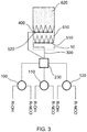
- a device with three mixing heads 100, 110 and 120 is shown here.
- Each of these three mixing heads receives a product stream with a polyol component R-OH and a product stream with an isocyanate component R-NCO.
- R-OH and R-NCO do of course not stand for monoalcohols and monoisocyanates, but generally for polyols and polyisocyanates and blowing agents and other additives that are still present in these feed streams.
- the mixing heads 100, 110, 120 combine their feed streams to form product streams which are fed to a distributor 230 connected to the mixing heads.
- the distributor 230 therefore has at least as many inputs as there are mixing heads.
- the product streams thus contain the foamable reaction mixture.
- the product stream is homogenized in the distributor 230 so that, for example, differences in the progress of the reaction over time or differences in the properties of the educt streams caused by time are compensated for.
- time-related differences in the properties of the educt streams it can be, for example, differences that are based on density fluctuations or fluctuations in the delivery rate of the educt streams to the mixing heads.
- the geometry of the distributor is preferably chosen so that the path of the homogenized reaction mixture to the discharge lines is of the same length. It is also advantageous if the cross-section of the distributor outlets is identical for all distributor outlets. The cross-sections of the distributor inlets, on the other hand, can also be different.
- the material of the distributor can be selected from steel, stainless steel, aluminum and plastics. In any case, the selected material must be able to withstand the pressures and temperatures in the mixing head.
- a distributor 230 can be constructed, for example, in such a way that two distributor heads, such as those shown in FIG EP 1 857 248 A2 ([0023], Fig. 1 ) are described under the designation "distributor head", can be connected in series.
- the flow through the first distributor head is reversed, i.e. the product flows coming from the mixing heads enter the first (reversed) distributor head via the several openings, are homogenized there and leave the distributor head as a product flow, which then enters another distributor head, where it is again distributed over several product streams. This is in FIG 2 shown in more detail.
- the reaction mixture leaves the distributor 230 via 7 discharge lines 300, which each end in discharge openings 400.
- the distributor has fifteen discharge lines 300.
- the discharge lines 300 can be designed to be flexible or rigid, flexible discharge lines being preferred.
- the discharge lines 300 are attached to a fastening rail 500, as a result of which the position of the discharge openings 400 is fixed.
- the reaction mixture leaves the individual discharge openings 400 and contacts a cover layer 10, represented by its dashed outline and moving away from the discharge openings, essentially over its entire width.
- a cover layer represented by its dashed outline and moving away from the discharge openings, essentially over its entire width.
- the individual strips of the reaction mixture combine to form the foam layer 600 on the cover layer.
- the number of mixing heads in these embodiments of the device according to the invention and the method according to the invention can be 2, 3 (as shown here), 4, 5, 6 or even greater.
- the number of discharge lines per distributor can be 7, 8, 9, 10, 11, 12, 13, 14, 15 (as shown here) or even greater.
- This embodiment has the additional advantage that one basically only has to work with one quality of the reaction mixture.
- Another advantage over existing outlet systems is that precise positioning of the outlet streams, both symmetrical and asymmetrical, can be achieved through the use of flexible hoses, which are preferably flexible. This can lead to advantages in the panel geometry or it allows targeted product application, for example in the beads of a roof element. This application method can be used for the production of metal panel sandwich composite elements, insulation panels and continuous blocks.
- Casting rakes that can be used here can be used, for example, as single casting rakes or pairs of casting rakes, as in EP 1 857 248 A2 , EP 2 614 944 A1 or EP 2 804 736 A1 described, be executed.
- the inlet to the casting rake (s) can be, for example, in the middle or on the side.
- each of these three mixing heads shows a device with three mixing heads 100, 110 and 120.
- Each of these three mixing heads receives a product stream with a polyol component R-OH and a product stream with an isocyanate component R-NCO.
- R-OH and R-NCO do of course not stand for monoalcohols and monoisocyanates, but generally for polyols and polyisocyanates and in these feed streams Propellants and other additives that are still present.
- the mixing heads 100, 110, 120 combine their feed streams to form product streams which are fed to a distributor 230 connected to the mixing heads.
- the product streams thus contain the foamable reaction mixture.
- the product stream is homogenized in the distributor 230 so that, for example, differences in the progress of the reaction over time or differences in the properties of the educt streams due to time are compensated for.
- time-related differences in the properties of the educt streams it can be, for example, differences that are based on density fluctuations or fluctuations in the delivery rate of the educt streams to the mixing heads.
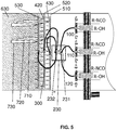
- the reaction mixture leaves the distributor 230 via discharge lines 300, which each end in casting rakes 500, 510, 520, 530 with discharge openings 400, 410, 420, 430.
- the distributor has three discharge lines 300, in which FIG. 3rd
- the embodiment shown is one or more discharge lines 300, in FIG. 4th it is a discharge line which, in the exemplary case shown, represents a direct connection to a casting rake 400.
- FIG. 5 there are three discharge lines 300.
- FIG. 3rd there can be two discharge services, it can - as in FIG.
- the discharge lines 300 can be designed to be flexible or rigid, flexible discharge lines being preferred.
- FIG. 5 a possible distributor 230, which homogenizes and redistributes the product streams emerging from the mixing heads, is shown in more detail.
- two distributor heads 231, 232 as shown, for example, in FIG EP 1 857 248 A2 ([0023], Fig. 1 ) are described under the designation "distributor head", can be connected in series.
- the flow through the first distributor head 231 is reversed, i.e. the product flows coming from the mixing heads enter the first (reversed) distributor head via the several openings, are homogenized there and leave the distributor head as a product flow which then flows into a further distributor head 232 occurs, where it is again distributed over several product streams.
- a pipe branch such as a T-piece or a Y-piece, in particular a T-shaped branch of the discharge line, can also be used. Will be like in FIG. 4th If the product flow is shown only fed to one discharge line (in this case directly to the casting rake), the further distributor head 232 can be omitted entirely.
- the reaction mixture leaves the individual discharge openings 400 of the casting rakes 500, 510, 520, 530 and makes contact with a cover layer, not shown, moving away from the discharge openings. Due to the expansion of the foaming reaction mixture, the unite individual strips of the reaction mixture for foam layer 600 on the cover layer.
- the number of mixing heads in these embodiments of the device according to the invention and the method according to the invention can be 2, 3 (as shown here), 4, 5, 6 or even greater.
- the number of casting rakes can be 3, (as in FIG. 2 shown), 2 (as in FIG. 3rd shown), 4, 5, 6 or even larger.
- the number of openings per casting rake can be 4, 5 (as shown here), 6, 7, 8, 9, 10 or even greater.
- the device according to the invention contains 2, 3 or 4 mixing heads and only one casting rake or a pair of casting rakes (as in FIG. 4th shown).
- Casting rakes that can be used here can be used, for example, as single casting rakes or pairs of casting rakes, as in EP 1 857 248 A2 , EP 2 614 944 A1 or EP 2 804 736 A1 described, be executed.
- the inlet to the casting rake (s) can be, for example, in the middle or on the side. This application method can be used for the production of metal panel sandwich composite elements, insulation panels and continuous blocks.
- This embodiment has the additional advantage that one basically only has to work with one quality of the reaction mixture.
- Another advantage over existing outlet systems is that precise positioning of the outlet streams, both symmetrical and asymmetrical, can be achieved through the use of flexible hoses, which are preferably flexible. This can lead to advantages in the panel geometry or it allows targeted product application, for example in an asymmetrical roof panel.
- At least two casting rakes 520 can be used in the device and in the method and for at least two of the casting rakes 520 to be arranged next to one another as seen transversely to the direction of movement of the cover layer and to be arranged one behind the other as seen in the direction of movement of the cover layer.
- This arrangement is in FIG. 2 shown.
- the three casting rakes 520 are in FIG. 2 arranged essentially next to each other.
- the fact that the middle casting rake is offset somewhat to the rear is intended to make it clear that such casting rakes have certain space requirements that may preclude positioning them directly next to one another.
- At least two casting rakes 510, 520 can be used in the device and in the method and at least two of the casting rakes 510, 520, viewed in the direction of movement of the cover layer, to be arranged directly one behind the other or slightly offset one behind the other, so that a casting rake from the discharge openings 400 510 discharged reaction mixture at least partially contacted from the discharge openings 400 of the other casting rake 520 reaction mixture discharged.
- This arrangement is in FIG. 3rd shown.
- the reaction mixture emerging from the casting rake 510 can flow between the flows from the other casting rake 520, so that an even better flow of the flows is achieved.
- the reaction mixture leaves the individual discharge openings 400, 410, 420 of the casting rakes 500, 510, 520, 530 and contacts a cover layer 10, represented by its dashed outline and moving away from the discharge openings, essentially over its entire width.
- a cover layer 10 represented by its dashed outline and moving away from the discharge openings, essentially over its entire width.
- the individual strips of the reaction mixture combine to form the foam layer 610, 620, 630 on the cover layer 10.
- the slight offset of the casting rakes that may be present is in their The order of magnitude depends on the number of casting rakes and the distance between the outlet openings.
- the offset of the casting rakes with respect to one another is at most a length which corresponds to 50% of the distance between two adjacent outlet openings of the casting rakes.
- a preferred arrangement is that the three casting rakes are offset from one another by a length which corresponds to approximately 1/3 of the distance between two adjacent outlet openings 400 of the casting rakes. This arrangement is in FIG. 5 shown.
- the individual strips of the reaction mixture 710, 720, 730 then combine again to form a foam layer 630.
- the order can be carried out in and against the direction of the belt. Even in one embodiment, as shown in one of the figures, it can be advantageous that not all casting rakes are placed at the same angle to the cover layer.
Description
- Die vorliegende Erfindung betrifft ein Verfahren und eine Vorrichtung zum Auftragen einer schäumbaren Reaktionsmischung auf ein sich bewegendes Deckschicht, wobei die Reaktionsmischung aus Austragsöffnungen auf die Deckschicht aufgetragen wird und die Deckschicht sich mit einer Geschwindigkeit von ≥ 15 Metern pro Minute relativ zu den Austragsöffnungen bewegt.
- Verbundelemente aus einer Deckschicht und einem Isolierkern werden heutzutage in vielen Industriebereichen eingesetzt. Der grundlegende Aufbau solcher Verbundelemente besteht dabei aus einer Deckschicht, auf welche ein isolierend wirkender Werkstoff aufgebracht wird. Als Deckschichten können dabei beispielsweise Bleche aus beschichtetem Stahl, Edelstahl, Aluminium, Kupfer oder Legierungen der beiden letztgenannten eingesetzt werden. Darüber hinaus können auch Dämmplatten aus einer Kombination aus Deckschichten und Isolierkern hergestellt werden. Es können Kunststofffolien, Aluminiumfolien, Holz, Glasfaser- oder Mineralfaservliese sowie cellulosehaltige Materialien wie Papier, Pappe oder Pappmaché als Deckschichtmaterialien eingesetzt werden. Oft werden Mehrschichtdeckschichten aus z. B. Aluminium und Papier verwendet. Die Wahl des geeigneten Deckschichtmaterials hängt dabei von dem beabsichtigten Einsatzgebiet der Verbundelemente oder Dämmplatte und den sich daraus ergebenden Materialanforderungen ab. Als Isolierkern können insbesondere Schaumstoffe auf Basis von Polyurethan (PUR) und/oder Polyisocyanurat (PIR) eingesetzt werden.
- Dämmplatten werden häufig im Haus- oder Wohnungs-Bau eingesetzt. Neben der Verwendung von Verbundelementen zur Isolierung von beispielsweise Kühlhäusern finden sie auch immer häufiger Anwendung als Fassadenelemente an Gebäuden oder als Elemente von Industrietüren wie beispielsweise Sektionaltore. Entsprechende Verbundelemente, im Folgenden auch als Sandwich-Verbundelemente bezeichnet, zeigen durch ihre Deckschicht eine dem verwendeten Material entsprechende Stabilität und Oberflächengestaltung, während der aufgebrachte Schaumstoff entsprechende wärmeisolierende Eigenschaften verleiht.
- Zur Herstellung entsprechender Dämmplatten oder Verbundelemente wird auf eine bereitgestellte Deckschicht ein schäumendes Reaktionsgemisch mittels einer Auftragsvorrichtung aufgebracht. Hierzu werden zum Beispiel bei der Verwendung von Schaumstoffen auf Basis von Isocyanaten die entsprechenden Polyol-Komponenten und Isocyanat-Komponenten miteinander gemischt und auf die Deckschicht aufgetragen, auf welcher sie aufschäumen und aushärten.
- Als Auftragsvorrichtung zur Aufbringung des schäumenden Reaktionsgemisches auf die Deckschicht kommen häufig Rohre zum Einsatz, welche entlang ihrer Längserstreckung mit einer Mehrzahl von Bohrungen versehen sind, aus welchen das in das Rohr eingebrachte Reaktionsgemisch austreten kann. Solche Rohre werden üblicherweise als Gießharken bezeichnet.
- Für schnell laufende Produktionsverfahren für derartige Verbundelemente, sogenannte Schnellläufer, ist eine Technologie namens "6-Finger-Laydown" bekannt. Diese auch als "American" oder "US"-Technologie bezeichnete Vorgehensweise benutzt drei Mischköpfe mit jeweils zwei Austragsvorrichtungen pro Mischkopf. Man hat hier durch die drei Produktströme eventuell sehr unterschiedliche Auftragsmischungen (Reaktionsaktivitätszustände) über die Breite der Produktionsanlage, die zu Problemen mit zum Beispiel Abbläsern, Lunkern etc. führen können. Zusätzlich hat man oft Probleme mit dem Ver- und Ineinander-Laufen des aufsteigenden Reaktionsgemischs, was zu Dimensionsproblemen führen kann. Bei drei Mischköpfen mit ihren sechs Produktströmen können die ausgehärteten Schaumstränge im Endprodukt noch optisch wahrgenommen werden, was als nachteilig angesehen wird.
-
EP 1 857 248 A2 beschreibt eine Auftragsvorrichtung zur Herstellung von über die Reaktionsfläche gleichzeitig auftragenden und gleichmäßig aufschäumenden Schäumen, wobei die Vorrichtung einen Mischkopf, einen Verteilerkopf , mindestens 3 oder mehr an den Verteilerkopf angebrachte, Auslaufleitungen , die quer zur Ausströmrichtung an einem Gestell, das starr ist, befestigt sind, enthält. Eine Vorrichtung zur Herstellung von Sandwich-Verbundelementen oder Dämmplatten wird ebenfalls offenbart, welche wenigstens zwei Zuführvorrichtungen für eine obere und eine untere Deckschicht, ein umlaufendes Band zur Führung der Deckschichten, an die eine Auftragsvorrichtung für eine geschäumte Kernschicht, eine Formstrecke und eine Ablängvorrichtung hintereinander geschaltet sind. -
WO 2010/089041 A2 offenbart eine Vorrichtung zum Auftragen von schäumbaren Reaktionsmischungen umfassend einen Mischkopf, einen strömungstechnisch hinter dem Mischkopf liegenden Verteilerkopf, mindestens drei an dem Verteilerkopf angebrachte Austrittleitungen, eine Zuleitung einer Komponente A zum Mischkopf, eine Zuleitung einer Komponente B zum Mischkopf, mindestens einen Statikmischer zur Durchmischung eines inerten Gases und der Komponente A, der Komponente B oder eines Gemisches der Komponenten A und B, mindestens eine Zuleitung auf der Hochdruckseite für das unter erhöhtem Druck stehende inerte Gas und mindestens eine Mess- und Regeleinheit zur Einstellung der gewünschten Drücke der Komponenten am Mischkopf. -
EP 2 233 271 A1 betrifft eine Vorrichtung zum Auftrag von aufschäumenden Reaktionsgemischen umfassend (a) einen Mischkopf zum Vermischen von Rohmaterialien zur Herstellung des Schaums, (b) einen strömungstechnisch hinter dem Mischkopf liegenden Verteilerkopf, (c) mindestens drei an dem Verteilerkopf angebrachte Schlauchleitungen und (d) mindestens drei stationäre Gießharken zum Auftragen des Gemischs der Rohmaterialien zur Schaumbildung auf ein bewegtes Deckschicht. -
EP 2 614 944 A1 beschreibt eine Vorrichtung zum Auftragen eines aufschäumenden Reaktionsgemisches auf eine Deckschicht , insbesondere zur Herstellung eines Verbundelementes, umfassend mindestens eine Gießharke mit einem rohrförmigen Hohlkörper, welcher Hohlkörper sich entlang einer Mittelachse erstreckt und wenigstens zwei Austrittsöffnungen zum Austritt des aufschäumenden Reaktionsgemisches aufweist, und wobei die Gießharke und die Deckschicht in einer Längsachse relativ zueinander bewegbar sind. Die Mittelachs der mindestens einen Gießharke und die Längsachse der Bewegung schließen einen Winkel von ≤ 80° zueinander ein. -
EP 2 804 736 A1 offenbart eine Vorrichtung zum Auftragen eines aufschäumenden Reaktionsgemisches auf eine Deckschicht, insbesondere zur Herstellung eines Verbundelementes, mindestens umfassend zwei Gießharken mit jeweils einem rohrförmigen Hohlkörper, welcher Hohlkörper sich entlang einer Mittelachse erstreckt und wenigstens zwei Austrittsöffnungen zum Austritt des aufschäumenden Reaktionsgemisches aufweist, wobei die Gießharken und die Deckschicht in einer Längsachse relativ zueinander bewegbar sind und wobei die Gießharken an einem Aufnahmeelement angeordnet sind. Die Anordnung der Gießharken am Aufnahmeelement weist jeweils ein Gelenk auf, mittels dem die Gießharken beweglich am Aufnahmeelement angeordnet sind und in einem Winkel von ≤ 80° zur Längsachse der Bewegung ausrichtbar sind. - Die Verwendung dieser Auftragstechnologien findet jedoch ihr Limit, regelmäßig sichtbar an mangelhafter Homogenität der hergestellten Schäume, wenn Verbundelemente wie Dämmplatten in sehr schnell laufender Produktionsweise hergestellt werden sollen und Reaktionsgemische mit sehr kurzen Startzeiten verarbeitet werden sollen.
- Als alternative Auftragstechnologie kann die sogenannte Kalibrierung verwendet werden. Diese führt zwar zu einer sehr hohen optischen Qualität, aber die Beherrschung des Verfahrens in der Produktion ist sehr schwierig.
- Auch die
WO 2016/37842 A - Die vorliegende Erfindung hat sich die Aufgabe gestellt, die Nachteile im Stand der Technik zumindest teilweise zu beheben. Insbesondere hat sie sich die Aufgabe gestellt, eine homogenere Produktqualität über die Breite einer Dämmplatte oder eines Schaum-Verbundelements zu erreichen.
- Erfindungsgemäß gelöst wird die Aufgabe durch ein Verfahren gemäß Anspruch 1 und eine Vorrichtung gemäß Anspruch 5. Vorteilhafte Weiterbildungen sind in den Unteransprüchen angegeben.
- Die Erfindung betrifft ein Verfahren zum Auftragen einer schäumbaren Reaktionsmischung auf ein sich bewegendes Deckschicht, wobei die Reaktionsmischung aus Austragsöffnungen auf die Deckschicht aufgetragen wird und die Deckschicht sich mit einer Geschwindigkeit von ≥ 15 Metern pro Minute relativ zu den Austragsöffnungen bewegt, wobei die Reaktionsmischung aus ≥ 7 Austragsöffnungen gleichzeitig auf die Deckschicht aufgetragen wird.
- Durch eine Verbesserung der Vorverteilung des Reaktionsgemischs in den Inhalt dieser Erfindung lässt sich der Prozess wesentlich einfacher steuern und führt nach einer kürzeren Anlaufphase in der Produktion zu einer besseren Produktqualität.
- Das erfindungsgemäße Verfahren ist vorzugsweise ein kontinuierliches Verfahren. Es eignet sich zur Herstellung von Schaum-Verbundelementen wie Dämmplatten in schnell laufender Produktionsweise. Die Deckschichtgeschwindigkeit beträgt dickenabhängig beispielsweise ≥ 10 bis ≤ 70 Meter pro Minute, vorzugsweise ≥ 15 Meter pro Minute, mehr bevorzugt ≥ 30 Meter pro Minute.
- Als Deckschicht oder Substrat eignen sich beispielsweise Metall-Folien, insbesondere AluminiumFolien, Mehrschichtdeckschichten, z. B. aus Aluminium und Papier, und Kunststoff-Folien. Die Breite der Deckschicht ist grundsätzlich nicht beschränkt. Beispielsweise kann die Deckschicht eine Breite zwischen 1000 und 1300 mm aufweisen, aber auch 2400 mm Breite sind möglich.
- Als Reaktionsmischung kommt insbesondere eine zu einem Polyurethan- und/oder Polyisocyanuratschaum reagierende Mischung in Frage. In einer Ausführungsform des erfindungsgemäßen Verfahrens umfasst daher die Reaktionsmischung ein Polyol A), ein Polyisocyanat B), gegebenenfalls Additive wie z. B. Stabilisatoren und Katalysatoren, gegebenenfalls ein oder mehrere Flammschutzmittel und ein (oder mehrere) Treibmittel C). Vorzugsweise ist das Polyol A) ausgewählt aus der Gruppe der Polyetherpolyole, Polyesterpolyole, Polycarbonatpolyole und /oder Polyetheresterpolyole. Die OH-Zahl des eingesetzten Polyols oder der eingesetzten Polyole kann beispielsweise > 100 mg KOH/g bis < 800 mg KOH/g betragen und die durchschnittliche OH-Funktionalität des eingesetzten Polyols oder der der eingesetzten Polyole ist ≥ 2. Die OH-Zahl gibt im Falle eines einzelnen zugesetzten Polyols dessen OH-Zahl an. Im Falle von Mischungen wird die mittlere OH-Zahl angegeben. Dieser Wert kann anhand von DIN 53240 bestimmt werden. Die durchschnittliche OH-Funktionalität der Polyole liegt beispielsweise in einem Bereich von ≥ 2 bis < 6.
- Verwendbare Polyetherpolyole sind beispielsweise Polytetramethylenglykolpolyether, wie sie durch Polymerisation von Tetrahydrofuran mittels kationischer Ringöffnung erhältlich sind. Ebenfalls geeignete Polyetherpolyole sind Additionsprodukte von Styroloxid, Ethylenoxid, Propylenoxid, Butylenoxide und oder Epichlorhydrin an di- oder polyfunktionelle Startermoleküle. Meistens werden Polyetherpolyole mit Ethylenoxid oder Propylenoxid als Kettenverlängerer verwendet.
- Geeignete Startermoleküle sind zum Beispiel Ethylenglykol, Diethylenglykol, Butyldiglykol, Glycerin, Diethylenglykol, Trimethylolpropan, Propylenglykol, Pentaerythrit, Sorbit, Saccharose, Ethylendiamin, Toluoldiamin, Triethanolamin, 1,4-Butandiol, 1,6-Hexandiol sowie niedermolekulare, Hydroxylgruppen aufweisende Ester derartiger Polyole mit Dicarbonsäuren.
- Verwendbare Polyesterpolyole sind unter Anderem Polykondensate aus Di- sowie weiterhin Tri-, und Tetraolen und Di- sowie weiterhin Tri- und Tetracarbonsäuren oder Hydroxycarbonsäuren oder Lactonen. Anstelle der freien Polycarbonsäuren können auch die entsprechenden Polycarbonsäureanhydride oder entsprechende Polycarbonsäureester von niederen Alkoholen zur Herstellung der Polyester verwendet werden.
- Beispiele für geeignete Diole sind Ethylenglykol, Butylenglykol, Diethylenglykol, Triethylenglykol, Polyalkylenglykole wie Polyethylenglykol, weiterhin 1,2-Propandiol, 1,3-Propandiol, 1,3-Butandiol, 1,3-Butandiol, 1,6-Hexandiol und Isomere, Neopentylglykol oder Hydroxypivalinsäureneopentylglykolester. Daneben können auch Polyole wie Trimethylolpropan, Glycerin, Erythrit, Pentaerythrit, Trimethylolbenzol oder Trishydroxyethylisocyanurat eingesetzt werden.
- Als Polycarbonsäuren können beispielsweise Phthalsäure, Isophthalsäure, Terephthalsäure, Tetrahydrophthalsäure, Hexahydrophthalsäure, Cyclohexandicarbonsäure, Adipinsäure, Azelainsäure, Sebacinsäure, Glutarsäure, Tetrachlorphthalsäure, Maleinsäure, Fumarsäure, Itaconsäure, Malonsäure, Korksäure, Bernsteinsäure, 2-Methylbernsteinsäure, 3,3-Diethylglutarsäure, 2,2-Dimethylbernsteinsäure, Dodekandisäure, Endomethylentetrahydrophthalsäure, Dimerfettsäure, Trimerfettsäure, Zitronensäure oder Trimellithsäure eingesetzt werden. Als Säurequelle können auch die entsprechenden Anhydride verwendet werden.
- Sofern die mittlere Funktionalität des zu veresternden Polyols > 2 ist, können zusätzlich auch Monocarbonsäuren wie Benzoesäure und Hexancarbonsäure mit verwendet werden. Hydroxycarbonsäuren, die als Reaktionsteilnehmer bei der Herstellung eines Polyesterpolyols mit endständigen Hydroxylgruppen mitverwendet werden können, sind beispielsweise Hydroxycapronsäure, Hydroxybuttersäure, Hydroxydecansäure, Hydroxystearinsäure und dergleichen. Geeignete Lactone sind unter anderem Caprolacton, Butyrolacton und Homologe. Verwendbare Polycarbonatpolyole sind Hydroxylgruppen aufweisende Polycarbonate, zum Beispiel Polycarbonatdiole. Diese sind durch Reaktion von Kohlensäurederivaten, wie Diphenylcarbonat, Dimethylcarbonat oder Phosgen, mit Polyolen, bevorzugt Diolen oder aus Kohlendioxid erhältlich.
- Beispiele derartiger Diole sind Ethylenglykol, 1,2- und 1,3-Propandiol, 1,3- und 1,4-Butandiol, 1,6-Hexandiol, 1,8-Octandiol, Neopentylglykol, 1,4-Bishydroxymethylcyclohexan, 2-Methyl-1,3-propandiol, 2,2,4-Trimethylpentandiol-1,3, Dipropylenglykol, Polypropylenglykole, Dibutylenglykol, Polybutylenglykole, Bisphenol A und lactonmodifizierte Diole der vorstehend genannten Art. Statt oder zusätzlich zu reinen Polycarbonatdiolen können auch Polyether-Polycarbonatdiole eingesetzt werden.
- Verwendbare Polyetheresterpolyole sind solche Verbindungen, die Ethergruppen, Estergruppen und OH-Gruppen enthalten. Organische Dicarbonsäuren mit bis zu 12 Kohlenstoffatomen sind zur Herstellung der Polyetheresterpolyole geeignet, vorzugsweise aliphatische Dicarbonsäuren mit > 4 bis < 6 Kohlenstoffatomen oder aromatische Dicarbonsäuren, die einzeln oder im Gemisch verwendet werden. Beispielhaft seien Korksäure, Azelainsäure, Decandicarbonsäure, Maleinsäure, Malonsäure, Phthalsäure, Pimelinsäure und Sebacinsäure sowie insbesondere Glutarsäure, Fumarsäure, Bernsteinsäure, Adipinsäure, Phthalsäure, Terephthalsäure und Isoterephthalsäure genannt. Als Derivate dieser Säuren können beispielsweise deren Anhydride sowie deren Ester und Halbester mit niedermolekularen, monofunktionellen Alkoholen mit > 1 bis < 4 Kohlenstoffatomen eingesetzt werden.
- Beispiele von geeigneten Polyisocyanaten B) sind 1,4-Butylendiisocyanat, 1,5-Pentandiisocyanat, 1,6- Hexamethylendiisocyanat (HDI), Isophorondiisocyanat (IPDI), 2,4- und/oder 2,4,4-Trimethylhexamethylendiisocyanat, die isomeren Bis(4,4'-isocyanatocyclohexyl)methane oder deren Mischungen beliebigen Isomerengehalts, 1,4-Cyclobexylendiisocyanat, 1,4-Phenylendiisocyanat, 2,4- und/oder 2,6-Toluylendiisocyanat (TDI), 1,5-Naphthylendiisocyanat, 2,2'-und/oder 2,4'- und/oder 4,4'-Diphenylmethandiisocyanat (MDI) oder höhere Homologe (polymeres MDI, pMDI), 1,3- und/oder 1,4-Bis-(2-isocyanato-prop-2-yl)-benzol (TMXDI), 1 ,3-Bis-(isocyanatomethyl)benzol (XDI), sowie Alkyl-2,6-diisocyanatohexanoate (Lysindiisocyanate) mit C1 bis C6-Alkylgruppen.
- Neben den vorstehend genannten Polyisocyanaten können anteilig auch modifizierte Diisocyanate mit Uretdion-, Isocyanurat-, Urethan-, Carbodiimid, Uretonimin, Allophanat-, Biuret-, Amid-, Iminooxadiazindion und/oder Oxadiazintrionstruktur sowie nicht-modifiziertes Polyisocyanat mit mehr als 2 NCO-Gruppen pro Molekül wie zum Beispiel 4-Isocyanatomethyl-1,8-octandiisocyanat (Nonantriisocyanat) oder Triphenylmethan-4,4',4"-triisocyanat mit eingesetzt werden.
- Es ist möglich, dass im Reaktionsgemisch die Anzahl der NCO-Gruppen im Isocyanat und die Anzahl der gegenüber Isocyanaten reaktiven Gruppen zu einer Kennzahl (Index) von 110 bis 600 führen. Bevorzugt zwischen 115 und 400. Diese Kennzahl kann auch in einem Bereich von > 180:100 bis < 330:100 oder aber auch von > 90:100 bis < 140:100 liegen.
- Die Reaktionsmischung enthält weiterhin so viel Treibmittel C), wie zur Erzielung einer dimensionsstabilen Schaummatrix und der gewünschten Rohdichte nötig ist. In der Regel sind dies 0,5 - 30 Gewichtsteile Treibmittel bezogen auf 100 Gewichtsteile der Komponente A. Als Treibmittel werden vorzugsweise physikalische Treibmittel ausgewählt aus wenigstens einem Mitglied der Gruppe bestehend aus Kohlenwasserstoffen, halogenierten Ethern und perfluorierten Kohlenwasserstoffen mit 1 bis 8 Kohlenstoffatomen eingesetzt. Unter "physikalischen Treibmitteln" werden im Rahmen der vorliegenden Offenbarung solche Verbindungen verstanden, die aufgrund ihrer physikalischen Eigenschaften leicht flüchtig sind und nicht mit der Isocyanatkomponente reagieren. Bevorzugt sind die einzusetzenden physikalischen Treibmittel ausgewählt aus Kohlenwasserstoffen (z. B. n-Pentan, iso-Pentan, cycloPentan, Butan, Isobutan), Ethern (z. B. Methylal), halogenierten Ethern, perfluorierte Kohlenwasserstoffe mit 1 bis 8 Kohlenstoffatomen (z. B. Perfluorhexan), sowie deren Gemischen untereinander. Auch bevorzugt ist der Einsatz von (hydro)fluorierten Olefinen, wie z.B. HFO 1233zd(E) (Trans-1-chlor-3,3,3-trifluor-1-propen) oder HFO 1336mzz(Z) (cis-1,1,1,4,4,4-Hexafluor-2-buten) oder Additive wie FA 188 von 3M (1,1,1,2,3,4,5,5,5-Nonafluor-4-(trifluormethyl)pent-2-en), sowie der Einsatz von Kombinationen dieser Treibmittel. In besonders bevorzugten Ausführungsformen wird als Treibmittel C) ein Pentanisomer oder ein Gemisch verschiedener Pentanisomeren eingesetzt. Außerordentlich besonders bevorzugt wird Cyclopentan als Treibmittel C) eingesetzt. Weitere Beispiele für bevorzugt eingesetzte Fluorkohlenwasserstoffe sind z.B. HFC 245fa (1,1,1,3,3-Pentafluorpropan), HFC 365mfc (1,1,1,3,3-Pentafluorbutan), HFC 134a oder deren Mischungen verwendet. Es können auch verschiedene Treibmittelklassen kombiniert werden.
- Insbesondere bevorzugt ist auch der Einsatz von (hydro)fluorierten Olefinen, wie z.B. HFO 1233zd(E) (Trans-1-chlor-3,3,3-trifluor-1-propen) oder HFO 1336mzz(Z) (cis-1,1,1,4,4,4-Hexafluor-2-buten) oder Additive wie FA 188 von 3M (1,1,1,2,3,4,5,5,5-Nonafluor-4oder2)-(trifluormethyl)pent-2-en und/oder 1,1,1,3,4,4,5,5,5- Nonafluor-4(oder2)-(trifluormethyl)pent-2-en), allein oder in Kombination mit anderen Treibmitteln. Diese haben den Vorteil, ein besonders niedriges Ozonabbaupotential (ODP) aufzuweisen und ein besonders niedriges Treibhauspotential (GWP) zu besitzen. Mit dem erfindungsgemäßen Verfahren lassen sich (hydro)fluorierte Olefine in vorteilhafter Weise als Treibmittel für Verbundsysteme einsetzen, da sich im Vergleich zu mit anderen Auftragstechniken hergestellten Verbundelementen Verbundelemente mit besseren Oberflächenstrukturen und verbesserter Haftung zur Deckschicht herstellen lassen.
- Zusätzlich oder auch statt der oben aufgeführten physikalischen Treibmittel können auch chemische Treibmittel (auch "Co- Treibmittel") verwendet werden. Bei diesen handelt es sich besonders bevorzugt um Wasser und / oder Ameisensäure. Vorzugsweise werden die chemischen Treibmittel zusammen mit physikalischen Treibmitteln verwendet. Bevorzugt werden die Co-Treibmittel in einer Menge bis 6 Gew.-%, besonders bevorzugt 0,5 bis 4 Gew.-% für die Verbundelemente, bezogen auf die Gesamtmenge an Verbindungen mit gegenüber Isocyanatgruppen reaktiven Wasserstoffatomen in der Komponente A.
- Bevorzugt wird für Verbundelemente eine Mischung aus 0 und 6,0 Gew.-% an Co-Treibmittel und 1,0 bis 30,0 Gew.-% an Treibmittel, jeweils bezogen auf 100 Gew.-% der Komponente A, eingesetzt. Das Mengenverhältnis von Co-Treibmittel zu Treibmittel kann aber auch je nach Bedarf von 1:7 bis 1:35 betragen.
- Das Reaktionsgemisch enthält weiterhin gegebenenfalls eine Katalysatorkomponente D), welche geeignet ist, die Treibreaktion, die Urethanreaktion und / oder die Isocyanuratreaktion (Trimerisierung) zu katalysieren. Die Katalysatorkomponenten können dem Reaktionsgemisch zudosiert oder auch ganz oder teilweise in der Isocyanat-reaktiven Komponente A) vorgelegt werden.
- Hierfür geeignet sind insbesondere eine oder mehrere katalytisch aktive Verbindungen ausgewählt aus den folgenden Gruppen:
D1) Aminische Katalysatoren, z.B. Amidine, wie 2,3-Dimethyl-3,4,5,6-tetrahydropyrimidin, tertiäre Amine, wie Triethylamin, Tributylamin, Dimethylcyclohexylamin, Dimethylbenzylamin, N-Methyl-, N-Ethyl-, N-Cyclohexylmorpholin, N,N,N',N'- Tetramethylethylendiamin, N,N,N',N'-Tetramethylbutandiamin, N,N,N',N'-Tetramethylhexandiamin-1,6, Pentamethyldiethylentriamin, Bis(2-dimethylaminoethyl)ether, Bis-(dimethylaminopropyl)-harnstoff, Dimethylpiperazin, 1,2-Dimethyl-imidazol, N,N',N"-Tris-(dimethylaminopropyl)hexahydrotriazin, Bis[2-(N,N-dimethylamino)ethyl]ether, 1-Aza-bicyclo-(3,3,0)-octan und 1,4-Diaza-bi-cyclo-(2,2,2)-octan, und Alkanolaminverbindungen, wie Triethanolamin, Triisopropanolamin, N-Methyl- und N-Ethyl-diethanolamin, N,N-Dimethylaminoethoxyethanol, N,N,N'-Trimethylaminoethyl-ethanolamin und Dimethylethanolamin. Besonders geeignete Verbindungen sind ausgewählt aus der Gruppe umfassend tertiäre Amine, wie Triethylamin, Tributylamin, Dimethylcyclohexylamin, Dimethylbenzylamin, N,N,N',N'- Tetramethylethylendiamin, Pentamethyldiethylentriamin, Bis(2-dimethylaminoethyl)ether, Dimethylpiperazin, 1,2-Dimethyl-imidazol und Alkanolaminverbindungen, wie Tris(dimethylaminomethyl)phenol, Triethanolamin, Triisopropanolamin, N-Methyl- und N-Ethyl-diethanolamin, N,N-Dimethylaminoethoxyethanol, N,N,N'-Trimethylaminoethyl-ethanolamin und Dimethylethanolamin, - In einer besonders bevorzugten Ausführungsform werden in der Katalysatorkomponente ein oder mehrere aminische Verbindungen gemäß folgender Struktur eingesetzt:
(CH3)2N-CH2-CH2-X-CH2-CH2-Y
wobei Y = NR2 oder OH, vorzugsweise Y = N(CH3)2 oder OH, besonders bevorzugt Y = N(CH3)2
und wobei X= NR oder O, vorzugsweise X= N-CH3 oder O, besonders bevorzugt X= N-CH3. Dabei ist jedes R unabhängig von jedem anderen R wählbar und stellt einen beliebig aufgebauten
organischen Rest mit mindestens einem C-Atom dar. Vorzugsweise ist R eine Alkylgruppe mit 1 bis 12 C-Atomen, insbesondere C1- bis C6-Alkyl, besonders bevorzugt Methyl und Ethyl, insbesondere Methyl. - D2) Carboxylate von Alkali- oder Erdalkalimetallen, insbesondere Na¬trium¬acetat, Natriumoctoat, Kaliumacetat, Kaliumoctoat, sowie Zinncarboxylate, z.B.. Zinn-(II)-acetat, Zinn-(II)-octoat, Zinn-(II)-ethylhexoat, Zinn-(II)-laurat, Dibutyl¬zinndiacetat, Di¬butyl¬zinndilaurat, Dibutylzinnmaleat und Dioctyl¬zinndiacetat. und Ammoniumcarboxylate. Insbesondere bevorzugt sind Natrium-, Kalium- und Ammoniumcarboxylate. Bevorzugte Carboxylate sind Formiate, Ethylhexanoate (=Octoate) und Acetate.
- Bevorzugt enthält der Katalysator einen oder mehrere Katalysatoren ausgewählt aus der Gruppe bestehend aus Kaliumacetat, Kaliumoctoat, Penta¬methyl¬diethylentriamin, N,N',N"-Tris-(dimethylaminopropyl)hexahydrotriazin, Tris(dimethylaminomethyl)phenol, Bis[2-(N,N-dimethylamino)ethyl] ether und N,N-Dimethylcyclohexylamin, besonders bevorzugt aus Penta¬methyl¬diethylentriamin, N,N',N"-Tris-(dimethylaminopropyl)hexahydrotriazin und N,N-Dimethylcyclohexylamin, besonders besonders bevorzugt aus Penta¬methyl¬diethylentriamin, N,N',N"-Tris-(dimethylaminopropyl)hexahydrotriazin und N,N-Dimethylcyclohexylamin in Kombination mit Kaliumacetat, Kaliumoctoat oder Kaliumformiat oder Natriumformiat
- Die zur Herstellung des Hartschaumstoffes nötigen Katalysatoren, insbesondere aminische Katalysatoren (D1) in Kombination mit als Trimerisationskatalysatoren eingesetzten Salze, werden in einer bevorzugten Ausführungsform in solcher Menge eingesetzt, dass z.B. auf kontinuierlich produzierenden Anlagen Elemente mit flexiblen Deckschichten mit Geschwindigkeiten bis zu 80 m/min je nach Elementstärke produziert werden können.
- Die Reaktivität der Reaktionsmischung wird i.d.R. mittels Katalysator (oder über andere die Reaktivität erhöhende Komponenten, z.B. Aminopolyether), auf die Bedürfnisse angepasst. So verlangt die Herstellung von dünnen Platten ein Reaktionsgemisch mit einer höheren Reaktivität als die Herstellung von dickeren Platten. Typische Parameter sind die Startzeit und die Abbindezeit als Maß für die Zeit, zu der das Reaktionsgemisch zu reagieren beginnt, und für den Zeitpunkt, an dem ein hinreichend stabiles Polymernetzwerk gebildet ist. Typische Startzeiten (gekennzeichnet durch den Beginn des Aufschäumens der Reaktionsmischung bei visueller Beurteilung) für die Verarbeitung mittels konventioneller Technik liegen im Bereich von 2s bis 50s.
- Mittels erfindungsgemäßem Verfahren lassen sich nun auch Reaktionsgemische mit hohen bzw. höheren Reaktivitäten, d.h. Startzeiten von <5s, insbesondere <2s, ganz besonders < 1s und Abbindezeiten von <25 s, insbesondere <20s und ganz besonders <14s vorteilhaft verarbeiten. Das erfindungsgemäße Verfahren kann insbesondere für die Herstellung von dünnen Platten vorteilhaft sein, da hier wenig Material für das Zusammenfließen zur Verfügung steht.
- Bevorzugt wird eine Kombination aus Katalysatorkomponenten D1 und D2 in dem Reaktionsgemisch verwendet. In diesem Fall sollte das molare Verhältnis so gewählt sein, dass das Verhältnis von D2/D1 zwischen 0,1 und 80 liegt, insbesondere zwischen 2 und 20. Kurze Abbindezeiten können zum Beispiel mit mehr als 0,9 Gew.-% Kalium-2-ethylhexanoat bezogen auf alle Komponenten des Reaktionsgemisches erzielt werden.
- Es ist vorgesehen, dass die Reaktionsmischung aus ≥ 7 Austragsöffnungen gleichzeitig auf die Deckschicht aufgetragen wird. Je höher die Anzahl der Austragsöffnungen ist, desto geringer werden die Abweichungen der Produktqualität im Querschnitt des erhaltenen Verbundelements (quer zur Bewegungsrichtung der Deckschicht gesehen) ausfallen. Vorzugsweise wird die Reaktionsmischung aus 8 Austragsöffnungen gleichzeitig auf die Deckschicht aufgetragen, mehr bevorzugt aus ≥ 12 Austragsöffnungen gleichzeitig auf die Deckschicht aufgetragen, noch mehr bevorzugt aus ≥ 15 Austragsöffnungen.
- Die erfindungsgemäße Vorrichtung gemäß Anspruch 5 ist zur Durchführung des erfindungsgemäßen Verfahrens geeignet. In einer solchen Vorrichtung zum Auftragen einer schäumbaren Reaktionsmischung auf eine sich bewegende Deckschicht, wobei die Reaktionsmischung aus Austragsöffnungen auf die Deckschicht aufgetragen wird, umfasst die Vorrichtung ≥ 7 Austragsöffnungen. Vorzugsweise umfasst die Vorrichtung ≥ 8 Austragsöffnungen, mehr bevorzugt aus ≥ 12 und noch mehr bevorzugt ≥ 15 Austragsöffnungen.
- Die vorliegende Erfindung wird anhand der nachfolgenden Figuren näher erläutert, ohne jedoch darauf beschränkt zu sein, wobei der Schutzumfang in den beigefügten Ansprüchen definiert ist.
FIG. 1-5 zeigen offenbarte Vorrichtungen bei der Durchführung von offenbarten Verfahren. Unter Bezugnahme aufFIG. 1 soll eine Ausführungsform der erfindungsgemäßen Vorrichtung und des erfindungsgemäßen Verfahrens erläutert werden. Die erfindungsgemäße Vorrichtung ist im Anspruch 5 definiert und umfasst weiterhin: - Eine Mehrzahl von Mischköpfen 100, 110, 120, wobei jeder Mischkopf eingerichtet ist, um zwei oder mehr Eduktströme zu einem Produktstrom zu mischen;
- Einen Verteiler 230, wobei der Verteiler ≥ 7 Austragsleitungen 300 aufweist, welche jeweils in einer Austragsöffnung 400 enden, der Verteiler mit den Produktströmen der Mischköpfe 100, 110, 120 verbunden ist und der Verteiler eingerichtet ist, um die Produktströme der Mischköpfe 100, 110, 120 zu vereinigen und hinsichtlich der stofflichen Zusammensetzung homogen auf seine Austragsleitungen 300 zu verteilen.
- Hier dargestellt ist ein Vorrichtung mit drei Mischköpfen 100, 110 und 120. Jeder dieser drei Mischköpfe empfängt einen Produktstrom mit einer Polyolkomponente R-OH und einen Produktstrom mit einer Isocyanatkomponente R-NCO. Die Bezeichnungen R-OH und R-NCO stehen selbstverständlich nicht für Monoalkohole und Monoisocyanate, sondern allgemein für Polyole und Polyisocyanate und in diesen Eduktströmen weiterhin vorhandenen Treibmitteln und sonstigen Additiven.
- Die Mischköpfe 100, 110, 120 vereinigen ihre Eduktströme zu Produktströmen, die einem mit den Mischköpfen verbundenen Verteiler 230 zugeführt werden. Der Verteiler 230 weist daher mindestens so viele Eingänge auf, wie Mischköpfe vorhanden sind. Die Produktströme enthalten somit die schäumbare Reaktionsmischung. In dem Verteiler 230 erfolgt eine Homogenisierung des Produktstroms, so dass beispielsweise Unterschiede im zeitlichen Reaktionsfortschritt oder zeitlich bedingte Unterschiede in den Eigenschaften der Eduktströme ausgeglichen werden. Bei zeitlich bedingten Unterschieden in den Eigenschaften der Eduktströme kann es sich beispielsweise um solche Unterschiede handeln, die auf Dichteschwankungen oder auf Schwankungen in der Förderleistung der Eduktströme zu den Mischköpfen beruhen.
- Die Geometrie des Verteilers ist bevorzugt so gewählt, dass die Wegstrecke der homogenisierten Reaktionsmischung zu den Austragsleitungen gleich lang ist. Des Weiteren ist es vorteilhaft, wenn der Querschnitt der Verteilerausgänge bei allen Verteilerausgängen identisch ist. Die Querschnitte der Verteilereingänge können dagegen auch unterschiedlich sein. Das Material des Verteilers kann ausgewählt sein aus Stahl, Edelstahl, Aluminium und Kunststoffen. In jedem Fall muss das ausgewählte Material den im Mischkopf herrschenden Drücken und Temperaturen standhalten.
- In einer bevorzugten Ausführungsform kann ein Verteiler 230 z.B. so aufgebaut sein, dass zwei Verteilerköpfe, wie sie beispielswiese in der
EP 1 857 248 A2 ([0023],Fig. 1 ) unter der Bezeichnung "Verteilerkopf" beschrieben sind, hintereinandergeschaltet werden. Dabei wird der erste Verteilerkopf in umgedrehter Richtung durchströmt, d.h. die aus den Mischköpfen kommenden Produktströme treten über die mehreren Öffnungen in den ersten (umgedrehten) Verteilerkopf ein, werden dort homogenisiert und verlassen den Verteilerkopf als ein Produktstrom, der dann in einen weiteren Verteilerkopf eintritt, wo er wieder auf mehrere Produktströme verteilt wird. Dies ist inFIG 2 detaillierter dargestellt. - Die Reaktionsmischung verlässt den Verteiler 230 über ≥ 7 Austragsleitungen 300, welche jeweils in Austragsöffnungen 400 enden. In der in
FIG. 1 dargestellten Ausführungsform weist der Verteiler fünfzehn Austragsleitungen 300 auf. Die Austragsleitungen 300 können flexibel oder starr ausgeführt sein, wobei flexible Austragsleitungen bevorzugt sind. Die Austragsleitungen 300 sind auf einer Befestigungsschiene 500 angebracht, wodurch die Position der Austragsöffnungen 400 fixiert wird. - Die Reaktionsmischung verlässt die einzelnen Austragsöffnungen 400 und kontaktiert eine durch ihren gestrichelten Umriss dargestellte, sich von den Austragsöffnungen fortbewegende Deckschicht 10 im Wesentlichen in ihrer gesamten Breite. Durch die Expansion der schäumenden Reaktionsmischung vereinigen sich die einzelnen Streifen der Reaktionsmischung zur Schaumschicht 600 auf der Deckschicht.
- Die mit dem zuvor diskutierten Vorrichtung durchführbare Ausführungsform des erfindungsgemäßen Verfahrens , die im Anspruch 1 definiert ist, umfasst die Schritte:
- Bereitstellen einer Mehrzahl von Mischköpfen 100, 110, 120, wobei jeder Mischkopf eingerichtet ist, um zwei oder mehr Eduktströme zu einem Produktstrom zu mischen;
- Bereitstellen eines Verteilers 230, wobei der Verteiler ≥ 7 Austragsleitungen 300 aufweist, welche jeweils in einer Austragsöffnung 400 enden, der Verteiler mit den Produktströmen der Mischköpfe 100, 110, 120 verbunden ist und der Verteiler eingerichtet ist, um die Produktströme der Mischköpfe 100, 110, 120 zu vereinigen und hinsichtlich der stofflichen Zusammensetzung homogen auf seine Austragsleitungen 300 zu verteilen;
- Mischen von zwei oder mehr Eduktströmen in jedem der Mischköpfe 100, 110, 120 unter Erhalt eines jeden der Mischköpfe verlassenden Produktstroms, wobei der Produktstrom eine schäumbare Reaktionsmischung umfasst;
- Vereinigen der Produktströme in dem Verteiler 230;
- Verteilen der vereinigten Produktströme auf die Austragsleitungen 300 des Verteilers 230;
- Auftragen der Reaktionsmischung aus den Austragsöffnungen 400 der Austragsleitungen 300 auf die Deckschicht 10.
- Die Anzahl der Mischköpfe in diesen Ausführungsformen der erfindungsgemäßen Vorrichtung und des erfindungsgemäßen Verfahrens kann 2, 3 (wie hier dargestellt), 4, 5, 6 oder noch größer sein. Die Anzahl der Austragsleitungen pro Verteiler kann 7, 8, 9, 10, 11, 12, 13, 14, 15 (wie hier dargestellt) oder noch größer sein.
- Bei dieser Ausführungsform werden ebenfalls die Unterschiede zwischen den ursprünglichen Reaktionsgemischen ausgeglichen und Probleme mit Verlaufen und Ineinander-Laufen des aufsteigenden Reaktionsgemischs sehr deutlich reduziert. Diese Ausführungsform hat den zusätzlichen Vorteil, dass man im Grunde nur mit einer Qualität des Reaktionsgemischs arbeiten muss. Ein weiterer Vorteil gegenüber bestehenden Auslaufsystemen ist, dass man eine genaue Positionierung der Auslaufströme, sowohl symmetrisch als auch asymmetrisch, durch die Verwendung von vorzugsweise flexiblen Schläuchen erreichen kann. Dieses kann zu Vorteilen in der Plattengeometrie führen oder es erlaubt eine gezielte Produktaufbringung, zum Beispiel in den Sicken eines Dachelements. Diese Auftragsmethodik kann für die Herstellung von Metallpaneel-Sandwichverbundelementen, Dämmplatten und Konti-Blöcken verwendet werden.
- Unter Bezugnahme auf
FIG. 2 ,FIG. 3 ,FIG.4 undFIG. 5 sollen weitere Ausführungsformen der Vorrichtung und des Verfahrens erläutert werden. Die erfindungsgemäße Vorrichtung ist im Anspruch 5 definiert und umfasst: - Eine Mehrzahl von Mischköpfen 100, 110, 120, wobei jeder Mischkopf eingerichtet ist, um zwei oder mehr Eduktströme zu einem Produktstrom zu mischen;
- Einen Verteiler 230, wobei der Verteiler eine oder mehrere Austragsleitungen (300) aufweist, der Verteiler mit den Produktströmen der Mischköpfe (100, 110, 120) verbunden ist und der Verteiler eingerichtet ist, um die Produktströme der Mischköpfe (100, 110, 120) zu vereinigen und hinsichtlich der stofflichen Zusammensetzung homogen auf die eine oder mehrere Austragsleitungen (300) zu verteilen.
- Eine oder mehrere Gießharken 510, 520, wobei die Anzahl der Gießharken der Anzahl der Austragsleitungen 300 des Verteilers 230 entspricht, jede Gießharke mit einer Austragsleitung verbunden ist und jede Gießharke ≥ 4 Austragsöffnungen (400) aufweist.
- Hier einsetzbare Gießharken können beispielsweise als Einzelgießharke oder Gießharkenpaare, wie in
EP 1 857 248 A2 ,EP 2 614 944 A1 oderEP 2 804 736 A1 beschrieben, ausgeführt sein. Der Zulauf zu der/den Gießharken kann beispielsweise mittig oder seitlich sein. - In
FIG. 2 ,FIG. 3 ,FIG.4 undFIG. 5 dargestellt ist jeweils eine Vorrichtung mit drei Mischköpfen 100, 110 und 120. Jeder dieser drei Mischköpfe empfängt einen Produktstrom mit einer Polyolkomponente R-OH und einen Produktstrom mit einer Isocyanatkomponente R-NCO. Die Bezeichnungen R-OH und R-NCO stehen selbstverständlich nicht für Monoalkohole und Monoisocyanate, sondern allgemein für Polyole und Polyisocyanate und in diesen Eduktströmen weiterhin vorhandenen Treibmitteln und sonstigen Additiven. - Die Mischköpfe 100, 110, 120 vereinigen ihre Eduktströme zu Produktströmen, die einem mit den Mischköpfen verbundenen Verteiler 230 zugeführt werden. Die Produktströme enthalten somit die schäumbare Reaktionsmischung. In dem Verteiler 230 erfolgt eine Homogenisierung des Produktstroms, so dass beispielsweise Unterschiede im zeitlichen Reaktionsfortschritt oder zeitlich bedingte Unterschiede in den Eigenschaften der Eduktströme ausgeglichen werden. Bei zeitlich bedingten Unterschieden in den Eigenschaften der Eduktströme kann es sich beispielsweise um solche Unterschiede handeln, die auf Dichteschwankungen oder auf Schwankungen in der Förderleistung der Eduktströme zu den Mischköpfen beruhen.
- Die Reaktionsmischung verlässt den Verteiler 230 über Austragsleitungen 300, welche jeweils in Gießharken 500, 510, 520, 530 mit Austragsöffnungen 400, 410, 420, 430 enden. In der in
FIG. 2 dargestellten Ausführungsform weist der Verteiler drei Austragsleitungen 300 auf, in der inFIG. 3 dargestellten Ausführungsform sind es eine oder mehr Austragsleitungen 300, inFIG. 4 ist es eine Austragsleitung, welche in dem dargestellten beispielhaften Fall einen direkten Anschluss zu einer Gießharke 400 darstellt. InFIG. 5 sind es drei Austragsleitungen 300. Zum Beispiel (FIG. 3 ) kann es sich um zwei Austragsleistungen handeln, es können - wie inFIG. 5 - auch drei Austragsleistungen zu drei Gießharken oder Gießharkenpaaren oder auch eine Austragsleistung zu einer Gießharke oder Gießharkenpaar (FIG. 4 ) zugeordnet sein. Die Austragsleitungen 300 können flexibel oder starr ausgeführt sein, wobei flexible Austragsleitungen bevorzugt sind. - In
FIG. 5 ist ein möglicher Verteiler 230, der die aus den Mischköpfen austretenden Produktströme homogenisiert und wieder verteilt, detaillierter gezeigt. Hier ist er so aufgebaut, dass zwei Verteilerköpfe 231, 232, wie sie beispielswiese in derEP 1 857 248 A2 ([0023],Fig. 1 ) unter der Bezeichnung "Verteilerkopf" beschrieben sind, hintereinandergeschaltet werden. Dabei wird der erste Verteilerkopf 231 in umgedrehter Richtung durchströmt, d.h. die aus den Mischköpfen kommenden Produktströme treten über die mehreren Öffnungen in den ersten (umgedrehten) Verteilerkopf ein, werden dort homogenisiert und verlassen den Verteilerkopf als ein Produktstrom, der dann in einen weiteren Verteilerkopf 232 eintritt, wo er wieder auf mehrere Produktströme verteilt wird. Wird wie inFig. 3 auf nur zwei Produktströme bzw. Austragsleitungen 300 aufgeteilt, kann statt des weiteren Verteilerkopfs 232 auch einfach eine Rohrleitungsverzweigung wie ein T-Stück oder ein Y-Stück, insbesondere eine T-förmige Verzweigung der Austragsleitung genutzt werden. Wird wie inFIG. 4 dargestellt der Produktstrom nur einer Austragsleitung zugetragen (in diesem Fall direkt der Gießharke), so kann der weitere Verteilerkopf 232 ganz entfallen. - Die Reaktionsmischung verlässt die einzelnen Austragsöffnungen 400 der Gießharken 500, 510, 520, 530 und kontaktiert eine nicht dargestellte, sich von den Austragsöffnungen fortbewegende Deckschicht. Durch die Expansion der schäumenden Reaktionsmischung vereinigen sich die einzelnen Streifen der Reaktionsmischung zur Schaumschicht 600 auf der Deckschicht.
- Die mit der zuvor diskutierten Vorrichtung durchführbare Ausführungsform des Verfahrens umfasst weiterhin die Schritte:
- Bereitstellen einer Mehrzahl von Mischköpfen 100, 110, 120, wobei jeder Mischkopf eingerichtet ist, um zwei oder mehr Eduktströme zu einem Produktstrom zu mischen;
- Bereitstellen eines Verteilers 230, wobei der Verteiler eine oder mehrere Austragsleitungen 300 aufweist, der Verteiler mit den Produktströmen der Mischköpfe 100, 110, 120 verbunden ist und der Verteiler eingerichtet ist, um die Produktströme der Mischköpfe 100, 110, 120 zu vereinigen und hinsichtlich der stofflichen Zusammensetzung homogen auf die eine oder mehrere Austragsleitungen 300 zu verteilen;
- Bereitstellen einer oder mehrerer Gießharken 510, 520, wobei die Anzahl der Gießharken der Anzahl der Austragsleitungen 300 des Verteilers 230 entspricht, jede Gießharke mit einer Austragsleitung verbunden ist und jede Gießharke ≥ 4 Austragsöffnungen (400) aufweist;
- Mischen von zwei oder mehr Eduktströmen in jedem der Mischköpfe 100, 110, 120 unter Erhalt eines jeden der Mischköpfe verlassenden Produktstroms, wobei der Produktstrom eine schäumbare Reaktionsmischung umfasst;
- Vereinigen der Produktströme in dem Verteiler 230;
- Verteilen der vereinigten Produktströme auf die eine oder mehrere Austragsleitungen 300 des Verteilers 230;
- Auftragen der Reaktionsmischung aus den Austragsöffnungen 400 der einen oder mehreren Gießharken 510, 520 auf die Deckschicht.
- Die Anzahl der Mischköpfe in diesen Ausführungsformen der erfindungsgemäßen Vorrichtung und des erfindungsgemäßen Verfahrens kann 2, 3 (wie hier dargestellt), 4, 5, 6 oder noch größer sein. Die Anzahl der Gießharken kann 3, (wie in
FIG. 2 dargestellt), 2 (wie inFIG. 3 dargestellt), 4, 5, 6 oder noch größer sein. Die Anzahl der Öffnungen pro Gießharke kann 4, 5 (wie hier dargestellt), 6, 7, 8, 9, 10 oder noch größer sein. In einer bevorzugten Ausführungsform enthält die erfindungsgemäße Vorrichtung 2, 3 oder 4 Mischköpfe und nur eine Gießharke bzw. ein Gießharkenpaar (wie inFIG. 4 dargestellt). - Hier einsetzbare Gießharken können beispielsweise als Einzelgießharke oder Gießharkenpaare, wie in
EP 1 857 248 A2 ,EP 2 614 944 A1 oderEP 2 804 736 A1 beschrieben, ausgeführt sein. Der Zulauf zu der/den Gießharken kann beispielsweise mittig oder seitlich sein. Diese Auftragsmethodik kann für die Herstellung von Metallpaneel-Sandwichverbundelementen, Dämmplatten und Konti-Blöcken verwendet werden. - Bei dieser Ausführungsform werden ebenfalls die Unterschiede zwischen den ursprünglichen Reaktionsgemischen ausgeglichen und Probleme mit Verlaufen und Ineinander-Laufen des aufsteigenden Reaktionsgemischs sehr deutlich reduziert. Diese Ausführungsform hat den zusätzlichen Vorteil, dass man im Grunde nur mit einer Qualität des Reaktionsgemischs arbeiten muss. Ein weiterer Vorteil gegenüber bestehenden Auslaufsystemen ist, dass man eine genaue Positionierung der Auslaufströme, sowohl symmetrisch als auch asymmetrisch, durch die Verwendung von vorzugsweise flexiblen Schläuchen erreichen kann. Dieses kann zu Vorteilen in der Plattengeometrie führen oder es erlaubt eine gezielte Produktaufbringung, zum Beispiel in einer unsymmetrischen Dachplatte.
- Es ist möglich, dass im Vorrichtung und im Verfahren wenigstens zwei Gießharken 520 eingesetzt werden und wenigstens zwei der Gießharken 520 quer zur Bewegungsrichtung der Deckschicht gesehen nebeneinander angeordnet sind und in Bewegungsrichtung der Deckschicht gesehen hintereinander angeordnet sind. Diese Anordnung ist in
FIG. 2 dargestellt. Die drei Gießharken 520 sind inFIG. 2 im Wesentlichen nebeneinander angeordnet. Dass die mittlere Gießharke etwas nach hinten versetzt ist, soll die Umstände verdeutlichen, dass solche Gießharken gewisse Raumerfordernisse haben, die eine Positionierung direkt nebeneinander gegebenenfalls ausschließen. - Es ist ebenfalls möglich, dass in der Vorrichtung und im Verfahren wenigstens zwei Gießharken 510, 520 eingesetzt werden und wenigstens zwei der Gießharken 510, 520 in Bewegungsrichtung der Deckschicht gesehen direkt hintereinander oder leicht versetzt hintereinander angeordnet sind, so dass aus den Austragsöffnungen 400 einer Gießharke 510 ausgetragene Reaktionsmischung zumindest teilweise aus den Austragsöffnungen 400 der anderen Gießharke 520 ausgetragene Reaktionsmischung kontaktiert. Diese Anordnung ist in
FIG. 3 dargestellt. Es kann die aus Gießharke 510 in Strömen austretende Reaktionsmischung zwischen die Ströme aus der anderen Gießharke 520 fließen, so dass man eine noch bessere Verfließung der Ströme erreicht. - Die Reaktionsmischung verlässt die einzelnen Austragsöffnungen 400, 410, 420 der Gießharken 500, 510, 520, 530 und kontaktiert eine durch ihren gestrichelten Umriss dargestellte, sich von den Austragsöffnungen fortbewegende Deckschicht 10 im Wesentlichen in ihrer gesamten Breite. Durch die Expansion der schäumenden Reaktionsmischung vereinigen sich die einzelnen Streifen der Reaktionsmischung zur Schaumschicht 610, 620, 630 auf der Deckschicht 10.
- Die gegebenenfalls vorhandene leichte Versetzung der Gießharken zueinander ist in ihrer Größenordnung abhängig von der Anzahl der Gießharken und des Abstands der Austrittsöffnungen. In einer besonders bevorzugten Ausführungsform beträgt die Versetzung der Gießharken zueinander maximal eine Länge, die 50 % des Abstands zweier benachbarter Austrittsöffnungen der Gießharken entspricht. Bei der Verwendung von drei Gießharken 510,520,530 ist eine bevorzugte Anordnung, dass die drei Gießharken zueinander jeweils um eine Länge versetzt, welche ca. 1/3 des Abstands zweier benachbarter Austrittsöffnungen 400 der Gießharken entspricht. Diese Anordnung ist in
FIG. 5 dargestellt. Die einzelnen Streifen der Reaktionsmischung 710, 720, 730 vereinigen sich dann wieder zu einer Schaumschicht 630. - Bei allen ausgeführten Austragssystemen kann der Auftrag in und gegen die Bandrichtung ausgeführt werden. Selbst in einer Ausführungsform, wie in einer der Figuren dargestellt, kann es vom Vorteil sein, dass nicht alle Gießharken mit dem gleichen Winkel zur Deckschicht platziert werden.
Claims (5)
- Verfahren zum Auftragen einer schäumbaren Reaktionsmischung auf eine sich bewegende Deckschicht (10), wobei die Reaktionsmischung aus Austragsöffnungen (400) auf die Deckschicht aufgetragen wird und die Deckschicht sich mit einer Geschwindigkeit von ≥ 15 Metern pro Minute relativ zu den Austragsöffnungen (400) bewegt,
wobei die Reaktionsmischung aus ≥ 7 Austragsöffnungen (400) gleichzeitig auf die Deckschicht (10) aufgetragen wird,
weiterhin umfassend die Schritte:- Bereitstellen einer Mehrzahl von Mischköpfen (100, 110, 120), wobei jeder Mischkopf eingerichtet ist, um zwei oder mehr Eduktströme zu einem Produktstrom zu mischen;- Bereitstellen eines Verteilers (230), wobei der Verteiler eine oder mehrere Austragsleitungen (300) aufweist, der Verteiler mit den Produktströmen der Mischköpfe (100, 110, 120) verbunden ist und der Verteiler eingerichtet ist, um die Produktströme der Mischköpfe (100, 110, 120) zu vereinigen und hinsichtlich der stofflichen Zusammensetzung homogen auf die eine oder mehrere Austragsleitungen (300) zu verteilen;- Bereitstellen einer oder mehrerer Gießharken (510, 520), wobei die Anzahl der Gießharken der Anzahl der Austragsleitungen (300) des Verteilers (230) entspricht, jede Gießharke mit einer Austragsleitung verbunden ist und jede Gießharke ≥ 4 Austragsöffnungen (400) aufweist;- Mischen von zwei oder mehr Eduktströmen in jedem der Mischköpfe (100, 110, 120) unter Erhalt eines jeden der Mischköpfe verlassenden Produktstroms, wobei der Produktstrom eine schäumbare Reaktionsmischung umfasst;- Vereinigen der Produktströme in dem Verteiler (230);- Verteilen der vereinigten Produktströme auf die eine oder mehrere Austragsleitungen (300) des Verteilers (230);- Auftragen der Reaktionsmischung aus den Austragsöffnungen (400) der einen oder mehreren Gießharken (510, 520) auf die Deckschicht (10). - Verfahren gemäß Anspruch 1, wobei wenigstens zwei Gießharken (510, 520) eingesetzt werden und wenigstens zwei der Gießharken (510, 520) quer zur Bewegungsrichtung der Deckschicht (10) gesehen nebeneinander angeordnet sind und in Bewegungsrichtung der Deckschicht (10) gesehen hintereinander angeordnet sind.
- Verfahren gemäß Anspruch 2, wobei die wenigstens zwei Gießharken (510, 520) um eine Länge, welche maximal 50 % des Abstands zweier benachbarter Austragsöffnungen (400) der Gießharken (510, 520) beträgt, versetzt zueinander angeordnet sind.
- Verfahren gemäß einem der vorhergehenden Ansprüche, wobei die Reaktionsmischung ein Polyol, ein Polyisocyanat und ein Treibmittel umfasst.
- Vorrichtung zum Auftragen einer schäumbaren Reaktionsmischung auf ein sich bewegendes Deckschicht, wobei die Reaktionsmischung aus Austragsöffnungen (400) auf die Deckschicht (10) aufgetragen wird,
wobei die Vorrichtung ≥ 7 Austragsöffnungen (400) umfasst und weiterhin umfasst:- eine Mehrzahl von Mischköpfen (100, 110, 120), wobei jeder Mischkopf eingerichtet ist, um zwei oder mehr Eduktströme zu einem Produktstrom zu mischen;- einen Verteiler (230), wobei der Verteiler eine oder mehrere Austragsleitungen (300) aufweist, der Verteiler mit den Produktströmen der Mischköpfe (100, 110, 120) verbunden ist und der Verteiler eingerichtet ist, um die Produktströme der Mischköpfe (100, 110, 120) zu vereinigen und hinsichtlich der stofflichen Zusammensetzung homogen auf die eine oder mehrere Austragsleitungen (300) zu verteilen;- eine oder mehrere Gießharken (510, 520), wobei die Anzahl der Gießharken der Anzahl der Austragsleitungen (300) des Verteilers (230) entspricht, jede Gießharke mit einer Austragsleitung verbunden ist und jede Gießharke ≥ 4 Austragsöffnungen (400) aufweist.
Priority Applications (1)
| Application Number | Priority Date | Filing Date | Title |
|---|---|---|---|
| PL18701201T PL3576922T3 (pl) | 2017-01-31 | 2018-01-30 | Sposób i urządzenie do wytwarzania piankowych elementów kompozytowych |
Applications Claiming Priority (2)
| Application Number | Priority Date | Filing Date | Title |
|---|---|---|---|
| EP17154071 | 2017-01-31 | ||
| PCT/EP2018/052247 WO2018141735A1 (de) | 2017-01-31 | 2018-01-30 | Verfahren und vorrichtung zur herstellung von schaum-verbundelementen |
Publications (2)
| Publication Number | Publication Date |
|---|---|
| EP3576922A1 EP3576922A1 (de) | 2019-12-11 |
| EP3576922B1 true EP3576922B1 (de) | 2021-06-09 |
Family
ID=58158762
Family Applications (1)
| Application Number | Title | Priority Date | Filing Date |
|---|---|---|---|
| EP18701201.8A Active EP3576922B1 (de) | 2017-01-31 | 2018-01-30 | Verfahren und vorrichtung zur herstellung von schaum-verbundelementen |
Country Status (5)
| Country | Link |
|---|---|
| US (1) | US20190344484A1 (de) |
| EP (1) | EP3576922B1 (de) |
| CN (1) | CN110248791A (de) |
| PL (1) | PL3576922T3 (de) |
| WO (1) | WO2018141735A1 (de) |
Families Citing this family (1)
| Publication number | Priority date | Publication date | Assignee | Title |
|---|---|---|---|---|
| EP3804939A1 (de) | 2019-10-11 | 2021-04-14 | Covestro Deutschland AG | Verfahren und vorrichtung zur herstellung von schaum-verbundelementen |
Family Cites Families (13)
| Publication number | Priority date | Publication date | Assignee | Title |
|---|---|---|---|---|
| US4572435A (en) * | 1984-05-30 | 1986-02-25 | Owens-Corning Fiberglas Corporation | Foamable liquid distributing means |
| US4945854A (en) * | 1989-03-17 | 1990-08-07 | Mobay Corporation | Apparatus for the distribution of a foamable reaction mixture upon a moving base |
| DE4202736A1 (de) * | 1992-01-31 | 1993-08-05 | Elastogran Gmbh | Auftragsvorrichtung fuer mehrkomponenten-kunststoff, insbesondere polyurethan |
| US5846462A (en) * | 1997-05-16 | 1998-12-08 | Thompson; Edward J. | Method and apparatus for making high compression structural foam |
| DE102006022760A1 (de) * | 2006-05-16 | 2007-11-22 | Bayer Materialscience Ag | Strang-Technik, Vorrichtung und Verfahren |
| EP2216156A1 (de) | 2009-02-05 | 2010-08-11 | Bayer MaterialScience AG | Hochdruckvorrichtung |
| EP2233271A1 (de) * | 2009-03-25 | 2010-09-29 | Bayer MaterialScience AG | Sandwich-Verbundelemente |
| DE202009015838U1 (de) * | 2009-11-20 | 2010-02-18 | Basf Se | Vorrichtung zum Auftrag von flüssigen Reaktionsgemischen auf eine Deckschicht |
| EP2614944A1 (de) | 2012-01-16 | 2013-07-17 | Bayer Intellectual Property GmbH | Vorrichtung zum Auftragen eines aufschäumenden Reaktionsgemisches |
| EP2614943A1 (de) * | 2012-01-16 | 2013-07-17 | Bayer Intellectual Property GmbH | Vorrichtung zum Auftragen eines aufschäumenden Reaktionsgemisches |
| ES2820870T3 (es) | 2012-01-16 | 2021-04-22 | Covestro Intellectual Property Gmbh & Co Kg | Dispositivo para aplicar una mezcla de reacción espumante |
| WO2014133023A1 (ja) * | 2013-02-26 | 2014-09-04 | 旭化成建材株式会社 | フェノール樹脂発泡板及びその製造方法 |
| BR112017004668B1 (pt) * | 2014-09-11 | 2021-09-08 | Huntsman International Llc | Linha de produção |
-
2018
- 2018-01-30 WO PCT/EP2018/052247 patent/WO2018141735A1/de unknown
- 2018-01-30 US US16/468,538 patent/US20190344484A1/en not_active Abandoned
- 2018-01-30 PL PL18701201T patent/PL3576922T3/pl unknown
- 2018-01-30 EP EP18701201.8A patent/EP3576922B1/de active Active
- 2018-01-30 CN CN201880009485.7A patent/CN110248791A/zh active Pending
Also Published As
| Publication number | Publication date |
|---|---|
| WO2018141735A1 (de) | 2018-08-09 |
| US20190344484A1 (en) | 2019-11-14 |
| EP3576922A1 (de) | 2019-12-11 |
| PL3576922T3 (pl) | 2021-12-13 |
| CN110248791A (zh) | 2019-09-17 |
Similar Documents
| Publication | Publication Date | Title |
|---|---|---|
| WO2018141731A1 (de) | Verfahren und system zur herstellung von schaum-verbundelementen | |
| EP2234732B1 (de) | Verfahren und vorrichtung zur herstellung von verbundelementen auf der basis von schaumstoffen auf isocyanatbasis | |
| EP2125323B1 (de) | Verfahren zur herstellung von verbundkörpern auf der basis von schaumstoffen auf isocyanatbasis | |
| EP2804735B1 (de) | Verfahren zum auftragen eines aufschäumenden reaktionsgemisches | |
| EP2804736A1 (de) | Vorrichtung zum auftragen eines aufschäumenden reaktionsgemisches | |
| EP2411198A1 (de) | Sandwich-verbundelemente | |
| WO2018141721A1 (de) | Verfahren zur herstellung von polyurethan (pur) und polyurethan/polyisocyanurat (pur/pir) – hartschaumstoffen | |
| EP3576922B1 (de) | Verfahren und vorrichtung zur herstellung von schaum-verbundelementen | |
| EP3576923B1 (de) | Verfahren und vorrichtung zur herstellung von schaum-verbundelementen | |
| EP2614943A1 (de) | Vorrichtung zum Auftragen eines aufschäumenden Reaktionsgemisches | |
| WO2013014055A1 (de) | Pur-pir-hartschaumstoff mit verbesserter haftung in verbundelementen | |
| EP3804939A1 (de) | Verfahren und vorrichtung zur herstellung von schaum-verbundelementen | |
| DE102004023881A1 (de) | Gedämmtes Rohr, enthaltend mit Ameisensäure hergestelltes Polyurethan | |
| WO2013023965A1 (de) | Vorrichtung zum auftragen von aufschäumenden reaktionsgemischen | |
| WO2019096733A1 (de) | Variable vorrichtung und verfahren zum auftragen einer schäumbaren reaktionsmischung auf eine sich bewegende deckschicht | |
| EP3648974B1 (de) | Verfahren zur herstellung von verbundelementen mit gezieltem auftragen eines haftvermittlers | |
| EP4275857A1 (de) | Werkzeug zur herstellung von schaumstoffen |
Legal Events
| Date | Code | Title | Description |
|---|---|---|---|
| STAA | Information on the status of an ep patent application or granted ep patent |
Free format text: STATUS: UNKNOWN |
|
| STAA | Information on the status of an ep patent application or granted ep patent |
Free format text: STATUS: THE INTERNATIONAL PUBLICATION HAS BEEN MADE |
|
| PUAI | Public reference made under article 153(3) epc to a published international application that has entered the european phase |
Free format text: ORIGINAL CODE: 0009012 |
|
| STAA | Information on the status of an ep patent application or granted ep patent |
Free format text: STATUS: REQUEST FOR EXAMINATION WAS MADE |
|
| 17P | Request for examination filed |
Effective date: 20190902 |
|
| AK | Designated contracting states |
Kind code of ref document: A1 Designated state(s): AL AT BE BG CH CY CZ DE DK EE ES FI FR GB GR HR HU IE IS IT LI LT LU LV MC MK MT NL NO PL PT RO RS SE SI SK SM TR |
|
| AX | Request for extension of the european patent |
Extension state: BA ME |
|
| DAV | Request for validation of the european patent (deleted) | ||
| DAX | Request for extension of the european patent (deleted) | ||
| RAP1 | Party data changed (applicant data changed or rights of an application transferred) |
Owner name: COVESTRO DEUTSCHLAND AG |
|
| RAP1 | Party data changed (applicant data changed or rights of an application transferred) |
Owner name: COVESTRO INTELLECTUAL PROPERTY GMBH & CO. KG |
|
| GRAP | Despatch of communication of intention to grant a patent |
Free format text: ORIGINAL CODE: EPIDOSNIGR1 |
|
| STAA | Information on the status of an ep patent application or granted ep patent |
Free format text: STATUS: GRANT OF PATENT IS INTENDED |
|
| INTG | Intention to grant announced |
Effective date: 20210218 |
|
| GRAS | Grant fee paid |
Free format text: ORIGINAL CODE: EPIDOSNIGR3 |
|
| GRAA | (expected) grant |
Free format text: ORIGINAL CODE: 0009210 |
|
| STAA | Information on the status of an ep patent application or granted ep patent |
Free format text: STATUS: THE PATENT HAS BEEN GRANTED |
|
| AK | Designated contracting states |
Kind code of ref document: B1 Designated state(s): AL AT BE BG CH CY CZ DE DK EE ES FI FR GB GR HR HU IE IS IT LI LT LU LV MC MK MT NL NO PL PT RO RS SE SI SK SM TR |
|
| REG | Reference to a national code |
Ref country code: GB Ref legal event code: FG4D Free format text: NOT ENGLISH |
|
| REG | Reference to a national code |
Ref country code: CH Ref legal event code: EP Ref country code: AT Ref legal event code: REF Ref document number: 1400087 Country of ref document: AT Kind code of ref document: T Effective date: 20210615 |
|
| REG | Reference to a national code |
Ref country code: DE Ref legal event code: R096 Ref document number: 502018005611 Country of ref document: DE |
|
| REG | Reference to a national code |
Ref country code: IE Ref legal event code: FG4D Free format text: LANGUAGE OF EP DOCUMENT: GERMAN |
|
| REG | Reference to a national code |
Ref country code: NL Ref legal event code: FP |
|
| REG | Reference to a national code |
Ref country code: LT Ref legal event code: MG9D |
|
| PG25 | Lapsed in a contracting state [announced via postgrant information from national office to epo] |
Ref country code: FI Free format text: LAPSE BECAUSE OF FAILURE TO SUBMIT A TRANSLATION OF THE DESCRIPTION OR TO PAY THE FEE WITHIN THE PRESCRIBED TIME-LIMIT Effective date: 20210609 Ref country code: HR Free format text: LAPSE BECAUSE OF FAILURE TO SUBMIT A TRANSLATION OF THE DESCRIPTION OR TO PAY THE FEE WITHIN THE PRESCRIBED TIME-LIMIT Effective date: 20210609 Ref country code: LT Free format text: LAPSE BECAUSE OF FAILURE TO SUBMIT A TRANSLATION OF THE DESCRIPTION OR TO PAY THE FEE WITHIN THE PRESCRIBED TIME-LIMIT Effective date: 20210609 Ref country code: BG Free format text: LAPSE BECAUSE OF FAILURE TO SUBMIT A TRANSLATION OF THE DESCRIPTION OR TO PAY THE FEE WITHIN THE PRESCRIBED TIME-LIMIT Effective date: 20210909 |
|
| PG25 | Lapsed in a contracting state [announced via postgrant information from national office to epo] |
Ref country code: NO Free format text: LAPSE BECAUSE OF FAILURE TO SUBMIT A TRANSLATION OF THE DESCRIPTION OR TO PAY THE FEE WITHIN THE PRESCRIBED TIME-LIMIT Effective date: 20210909 Ref country code: LV Free format text: LAPSE BECAUSE OF FAILURE TO SUBMIT A TRANSLATION OF THE DESCRIPTION OR TO PAY THE FEE WITHIN THE PRESCRIBED TIME-LIMIT Effective date: 20210609 Ref country code: RS Free format text: LAPSE BECAUSE OF FAILURE TO SUBMIT A TRANSLATION OF THE DESCRIPTION OR TO PAY THE FEE WITHIN THE PRESCRIBED TIME-LIMIT Effective date: 20210609 Ref country code: SE Free format text: LAPSE BECAUSE OF FAILURE TO SUBMIT A TRANSLATION OF THE DESCRIPTION OR TO PAY THE FEE WITHIN THE PRESCRIBED TIME-LIMIT Effective date: 20210609 Ref country code: GR Free format text: LAPSE BECAUSE OF FAILURE TO SUBMIT A TRANSLATION OF THE DESCRIPTION OR TO PAY THE FEE WITHIN THE PRESCRIBED TIME-LIMIT Effective date: 20210910 |
|
| PG25 | Lapsed in a contracting state [announced via postgrant information from national office to epo] |
Ref country code: RO Free format text: LAPSE BECAUSE OF FAILURE TO SUBMIT A TRANSLATION OF THE DESCRIPTION OR TO PAY THE FEE WITHIN THE PRESCRIBED TIME-LIMIT Effective date: 20210609 Ref country code: PT Free format text: LAPSE BECAUSE OF FAILURE TO SUBMIT A TRANSLATION OF THE DESCRIPTION OR TO PAY THE FEE WITHIN THE PRESCRIBED TIME-LIMIT Effective date: 20211011 Ref country code: CZ Free format text: LAPSE BECAUSE OF FAILURE TO SUBMIT A TRANSLATION OF THE DESCRIPTION OR TO PAY THE FEE WITHIN THE PRESCRIBED TIME-LIMIT Effective date: 20210609 Ref country code: SM Free format text: LAPSE BECAUSE OF FAILURE TO SUBMIT A TRANSLATION OF THE DESCRIPTION OR TO PAY THE FEE WITHIN THE PRESCRIBED TIME-LIMIT Effective date: 20210609 Ref country code: SK Free format text: LAPSE BECAUSE OF FAILURE TO SUBMIT A TRANSLATION OF THE DESCRIPTION OR TO PAY THE FEE WITHIN THE PRESCRIBED TIME-LIMIT Effective date: 20210609 Ref country code: EE Free format text: LAPSE BECAUSE OF FAILURE TO SUBMIT A TRANSLATION OF THE DESCRIPTION OR TO PAY THE FEE WITHIN THE PRESCRIBED TIME-LIMIT Effective date: 20210609 Ref country code: ES Free format text: LAPSE BECAUSE OF FAILURE TO SUBMIT A TRANSLATION OF THE DESCRIPTION OR TO PAY THE FEE WITHIN THE PRESCRIBED TIME-LIMIT Effective date: 20210609 |
|
| REG | Reference to a national code |
Ref country code: DE Ref legal event code: R097 Ref document number: 502018005611 Country of ref document: DE |
|
| PLBE | No opposition filed within time limit |
Free format text: ORIGINAL CODE: 0009261 |
|
| STAA | Information on the status of an ep patent application or granted ep patent |
Free format text: STATUS: NO OPPOSITION FILED WITHIN TIME LIMIT |
|
| PG25 | Lapsed in a contracting state [announced via postgrant information from national office to epo] |
Ref country code: DK Free format text: LAPSE BECAUSE OF FAILURE TO SUBMIT A TRANSLATION OF THE DESCRIPTION OR TO PAY THE FEE WITHIN THE PRESCRIBED TIME-LIMIT Effective date: 20210609 |
|
| 26N | No opposition filed |
Effective date: 20220310 |
|
| PG25 | Lapsed in a contracting state [announced via postgrant information from national office to epo] |
Ref country code: AL Free format text: LAPSE BECAUSE OF FAILURE TO SUBMIT A TRANSLATION OF THE DESCRIPTION OR TO PAY THE FEE WITHIN THE PRESCRIBED TIME-LIMIT Effective date: 20210609 |
|
| PG25 | Lapsed in a contracting state [announced via postgrant information from national office to epo] |
Ref country code: MC Free format text: LAPSE BECAUSE OF FAILURE TO SUBMIT A TRANSLATION OF THE DESCRIPTION OR TO PAY THE FEE WITHIN THE PRESCRIBED TIME-LIMIT Effective date: 20210609 |
|
| REG | Reference to a national code |
Ref country code: CH Ref legal event code: PL |
|
| PG25 | Lapsed in a contracting state [announced via postgrant information from national office to epo] |
Ref country code: LU Free format text: LAPSE BECAUSE OF NON-PAYMENT OF DUE FEES Effective date: 20220130 |
|
| PG25 | Lapsed in a contracting state [announced via postgrant information from national office to epo] |
Ref country code: LI Free format text: LAPSE BECAUSE OF NON-PAYMENT OF DUE FEES Effective date: 20220131 Ref country code: CH Free format text: LAPSE BECAUSE OF NON-PAYMENT OF DUE FEES Effective date: 20220131 |
|
| PG25 | Lapsed in a contracting state [announced via postgrant information from national office to epo] |
Ref country code: IE Free format text: LAPSE BECAUSE OF NON-PAYMENT OF DUE FEES Effective date: 20220130 |
|
| PGFP | Annual fee paid to national office [announced via postgrant information from national office to epo] |
Ref country code: PL Payment date: 20230102 Year of fee payment: 6 Ref country code: IT Payment date: 20221229 Year of fee payment: 6 |
|
| PGFP | Annual fee paid to national office [announced via postgrant information from national office to epo] |
Ref country code: GB Payment date: 20231221 Year of fee payment: 7 |
|
| PGFP | Annual fee paid to national office [announced via postgrant information from national office to epo] |
Ref country code: NL Payment date: 20231226 Year of fee payment: 7 Ref country code: FR Payment date: 20231222 Year of fee payment: 7 |
|
| PGFP | Annual fee paid to national office [announced via postgrant information from national office to epo] |
Ref country code: BE Payment date: 20231227 Year of fee payment: 7 |
|
| REG | Reference to a national code |
Ref country code: AT Ref legal event code: MM01 Ref document number: 1400087 Country of ref document: AT Kind code of ref document: T Effective date: 20230130 |
|
| PG25 | Lapsed in a contracting state [announced via postgrant information from national office to epo] |
Ref country code: AT Free format text: LAPSE BECAUSE OF NON-PAYMENT OF DUE FEES Effective date: 20230130 |
|
| PG25 | Lapsed in a contracting state [announced via postgrant information from national office to epo] |
Ref country code: MK Free format text: LAPSE BECAUSE OF FAILURE TO SUBMIT A TRANSLATION OF THE DESCRIPTION OR TO PAY THE FEE WITHIN THE PRESCRIBED TIME-LIMIT Effective date: 20210609 Ref country code: CY Free format text: LAPSE BECAUSE OF FAILURE TO SUBMIT A TRANSLATION OF THE DESCRIPTION OR TO PAY THE FEE WITHIN THE PRESCRIBED TIME-LIMIT Effective date: 20210609 Ref country code: AT Free format text: LAPSE BECAUSE OF NON-PAYMENT OF DUE FEES Effective date: 20230130 |
|
| PGFP | Annual fee paid to national office [announced via postgrant information from national office to epo] |
Ref country code: DE Payment date: 20231220 Year of fee payment: 7 |