EP3576252A2 - Verfahren zum aufbringen von beschichtungen auf elektrische maschinenkomponenten - Google Patents
Verfahren zum aufbringen von beschichtungen auf elektrische maschinenkomponenten Download PDFInfo
- Publication number
- EP3576252A2 EP3576252A2 EP19176613.8A EP19176613A EP3576252A2 EP 3576252 A2 EP3576252 A2 EP 3576252A2 EP 19176613 A EP19176613 A EP 19176613A EP 3576252 A2 EP3576252 A2 EP 3576252A2
- Authority
- EP
- European Patent Office
- Prior art keywords
- coating
- component
- stator
- ceramic material
- electrical machine
- Prior art date
- Legal status (The legal status is an assumption and is not a legal conclusion. Google has not performed a legal analysis and makes no representation as to the accuracy of the status listed.)
- Granted
Links
Images





Classifications
-
- H—ELECTRICITY
- H02—GENERATION; CONVERSION OR DISTRIBUTION OF ELECTRIC POWER
- H02K—DYNAMO-ELECTRIC MACHINES
- H02K1/00—Details of the magnetic circuit
- H02K1/04—Details of the magnetic circuit characterised by the material used for insulating the magnetic circuit or parts thereof
-
- C—CHEMISTRY; METALLURGY
- C25—ELECTROLYTIC OR ELECTROPHORETIC PROCESSES; APPARATUS THEREFOR
- C25D—PROCESSES FOR THE ELECTROLYTIC OR ELECTROPHORETIC PRODUCTION OF COATINGS; ELECTROFORMING; APPARATUS THEREFOR
- C25D13/00—Electrophoretic coating characterised by the process
- C25D13/02—Electrophoretic coating characterised by the process with inorganic material
-
- C—CHEMISTRY; METALLURGY
- C25—ELECTROLYTIC OR ELECTROPHORETIC PROCESSES; APPARATUS THEREFOR
- C25D—PROCESSES FOR THE ELECTROLYTIC OR ELECTROPHORETIC PRODUCTION OF COATINGS; ELECTROFORMING; APPARATUS THEREFOR
- C25D13/00—Electrophoretic coating characterised by the process
- C25D13/12—Electrophoretic coating characterised by the process characterised by the article coated
-
- H—ELECTRICITY
- H02—GENERATION; CONVERSION OR DISTRIBUTION OF ELECTRIC POWER
- H02K—DYNAMO-ELECTRIC MACHINES
- H02K15/00—Processes or apparatus specially adapted for manufacturing, assembling, maintaining or repairing of dynamo-electric machines
- H02K15/10—Applying solid insulation to windings, stators or rotors, e.g. applying insulating tapes
-
- H—ELECTRICITY
- H02—GENERATION; CONVERSION OR DISTRIBUTION OF ELECTRIC POWER
- H02K—DYNAMO-ELECTRIC MACHINES
- H02K15/00—Processes or apparatus specially adapted for manufacturing, assembling, maintaining or repairing of dynamo-electric machines
- H02K15/12—Impregnating, moulding insulation, heating or drying of windings, stators, rotors or machines
-
- H—ELECTRICITY
- H02—GENERATION; CONVERSION OR DISTRIBUTION OF ELECTRIC POWER
- H02K—DYNAMO-ELECTRIC MACHINES
- H02K3/00—Details of windings
- H02K3/30—Windings characterised by the insulating material
-
- H—ELECTRICITY
- H02—GENERATION; CONVERSION OR DISTRIBUTION OF ELECTRIC POWER
- H02K—DYNAMO-ELECTRIC MACHINES
- H02K3/00—Details of windings
- H02K3/32—Windings characterised by the shape, form or construction of the insulation
- H02K3/34—Windings characterised by the shape, form or construction of the insulation between conductors or between conductor and core, e.g. slot insulation
- H02K3/345—Windings characterised by the shape, form or construction of the insulation between conductors or between conductor and core, e.g. slot insulation between conductor and core, e.g. slot insulation
Definitions
- Embodiments of the disclosure generally relate to methods of depositing coatings on electrical machine components. More particularly, embodiments of the disclosure relate to methods of depositing electrically insulating coatings on electrical machine components using electrophoretic processes.
- Certain electric machines such as electric generators and motors, typically employ a combination of a rotor and a stator to convert rotational energy into electrical energy and vice versa.
- the electrical machines may include slotted cores (e.g., magnetic cores) having electrical conductors (e.g., coil windings) disposed in slots thereof; the cores and the electrical conductors may be electrically insulated from one another to prevent grounding of the conductors to the core.
- insulation materials such as polymer films and insulation papers can be used as slot liners and/or ground wall insulation to provide electrical insulation between the coil windings and the slotted core in the electric machine.
- stator assembly or coil windings typically involve multiple steps and multiple parts that are assembled together. Use of multiple steps and multiple parts results in cumbersome manufacturing processes, and may also affect the machine's end performance and reliability.
- the disclosure relates to a method of forming an electrically insulating coating on a component of an electrical machine.
- the component of the electrical machine is an additively-manufactured stator component or a rotor component.
- the method includes coating a surface of the component with a ceramic material including a nitride, via an electrophoretic process, to form a first coating.
- the method further includes contacting the first coating deposited by the electrophoretic process with a thermoset resin to form a second coating; and curing the second coating to form the electrically insulating coating including the ceramic material dispersed in a polymer matrix.
- the disclosure relates to a component of an electrical machine including a surface coated with an electrically insulating coating using the method described herein.
- the disclosure relates to a method of forming a coating on a component of an electrical machine.
- the method includes coating a surface of the component with a ceramic material, via an electrophoretic process, to form a first coating.
- the method further includes contacting the first coating deposited by the electrophoretic process with a polymeric material to form a second coating; and post-processing the second coating to form the coating including the ceramic material dispersed in a polymer matrix.
- Approximating language may be applied to modify any quantitative representation that could permissibly vary without resulting in a change in the basic function to which it is related. Accordingly, a value solidified by a term or terms, such as “about”, and “substantially” is not to be limited to the precise value specified. In some instances, the approximating language may correspond to the precision of an instrument for measuring the value. Similarly, “free” may be used in combination with a term, and may include an insubstantial number, or trace amounts, while still being considered free of the solidified term.
- range limitations may be combined and/or interchanged, such ranges are identified and include all the sub-ranges contained therein unless context or language indicates otherwise.
- disposed inside refers to configurations in which at least portion of a component is disposed inside or within a portion of another component, and does not necessarily connotate that the entirety of the component needs to be disposed within another component.
- the counter electrode may be completely disposed inside the stator/rotor core or may be partially disposed inside the stator/rotor core.
- a portion of the stator/rotor coil may be disposed in the stator/rotor slots and another portion may be disposed outside the stator/rotor slots.
- a method of forming a coating on a component of an electrical machine includes coating a surface of the component with a ceramic material, via an electrophoretic process, to form a first coating.
- the method further includes contacting the first coating deposited by the electrophoretic process with a thermoset resin to form a second coating.
- the method furthermore includes heat-treating the second coating to form the coating including the ceramic material dispersed in a polymer matrix.
- Non-limiting examples of suitable electrical machines include a motor, a generator, a transformer, a toroid, an inductor, and combinations thereof.
- an electric machine refers to an electric motor that converts electric power to mechanical power or to an electric generator that converts mechanical power to electric power.
- the electric machine includes a rotor, a stator, and windings.
- windings typically refers to electrically insulated conductors wound into a coil.
- stator coil typically refers to electrically insulated conductors wound into a coil.
- stator coil typically refers to electrically insulated conductors wound into a coil.
- stator coil typically refers to electrically insulated conductors wound into a coil.
- stator coil typically refers to electrically insulated conductors wound into a coil.
- stator coil typically refers to electrically insulated conductors wound into a coil.
- stator coil typically refers to electrically insulated conductors wound into a coil.
- stator coil typically refers to electrical
- stator coil refers to stator windings
- rotor coil refers to rotor windings, independent of the method used for fabricating the windings.
- FIG. 1 is a perspective view of an embodiment of an electric machine 100 (e.g., electric generator 100) coupled to an engine 200 (e.g., an engine of an automobile or an aircraft). While the illustrated electric machine 100 is an electric generator, it may be appreciated that the methods discussed herein are applicable to other electric machines, such as electric motors.
- the electric generator 100 may be described relative to an axial direction 14, a radial direction 16, and a circumferential direction or an annular direction 18.
- the electric generator 100 includes a rotor assembly 120 and a stator assembly 140, which may be concentrically aligned about the axial direction 14 of the electric machine 10.
- the rotor assembly 120 is configured to rotate in the circumferential direction 10 relative to the stator assembly 140.
- the rotational energy e.g., the relative rotation between the rotor assembly 120 and the stator assembly 140
- the rotational energy is converted to electrical current in armature or power generation coil within the stator or rotor assembly, depending on the design of the generator 100.
- the rotor assembly 120 includes a rotor core 122 that has end faces 124.
- the rotor core 122 includes a bore 126.
- the rotor assembly is mounted on a shaft 127 such that the rotor core 122 rotates together with the shaft 127.
- the stator assembly 140 includes a stator core 142 having end faces 144. Further, the rotor assembly 120 and the stator assembly 140 generally both include coil windings, which are illustrated and discussed below with respect to FIGS. 2-4 .
- the rotor assembly 120 includes field windings that generate a magnetic field
- the stator assembly 140 includes armature or power generation windings that generate electrical power as the rotor assembly 120 rotates.
- the stator assembly 140 may include field windings, and rotor assembly 120 may include the armature or power generation windings.
- rotor assembly 120 may include the armature or power generation windings.
- FIGS 3-4 and discussed below, at least a portion of the rotor core 122, the stator core, 142, the rotor coil 123, and the stator coil 143 may be coated with a coating 150.
- the coating 150 is illustrated as being in contact with both the rotor core 122 and the stator core 142.
- embodiments wherein the coating 150 is in contact with only one of the rotor core 122 or the stator core 142 are also envisaged within the scope of the disclosure.
- the coating 150 is in contact with only one of the rotor coil 123 and the stator coil 143 are also envisaged within the scope of the disclosure. Further, the coating 150 may be coated on the entire surface or only a portion of the surface of the rotor core 122, the stator core 142, the rotor coil 123, or the stator coil 143.
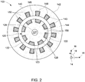
- FIG. 2 is a front view of the stator assembly 140 and the rotor assembly 120 of the embodiment of the generator 100, illustrated in FIG. 1 .
- the stator assembly 140 may include the stator core 142 having the end faces 144, an axially extending bore 146 (e.g., extending in the axial direction 14), and a plurality of slots or stator slots 148 that extend radially (e.g., in radial directions 16) away from the bore 146, and extend axially (e.g., in the axial direction 14) through the stator core 142.
- the stator core 142 may be formed from a series of laminations (e.g., laminated steel) or may take on other suitable forms, e.g., a unitary structure manufactured using an additive manufacturing technique.
- the illustrated stator assembly 140 includes stator coil (also referred to as stator windings) 143 having portions extending axially through the stator slots 148.
- the rotor assembly 120 is disposed within the bore 146 and extends axially along the bore 146.
- the illustrated rotor assembly 120 includes the rotor core 122 and a plurality of rotor slots 128 that extend radially (e.g., in radial directions 16) toward the shaft 127, and extend axially (e.g., in the axial direction 14) through the rotor core 122. There is typically a gap 130 (e.g., an air gap) present between the rotor assembly 120 and the stator core 142.
- the illustrated rotor assembly 120 includes rotor coil (also referred to as rotor windings) 123 having portions extending axially through the slots 128.
- the rotor coil 123 may be either a field coil or a power generation coil, depending on the electrical machine arrangement.
- the coating 150 may be selectively coated onto portions of the surfaces of the rotor core, 122, the rotor coil 123, the stator core 142, the stator coil 143, or combinations thereof.
- the different alternative configurations of the coated portions of the electrical machine 100 are further described herein with reference to FIGS 3-4 .
- FIG. 3 illustrates embodiments in which the coating 150 is selectively coated onto portions of the surfaces of one or both of the stator core 142 and the stator coil 143.
- the coating 150 may coated on at least a portion of the surfaces of the slots 148 of the stator core 142.
- the coating 150 may be additionally coated on at least a portion of the end faces 144 of the stator core 142.
- the coating 150 may be additionally or alternatively coated on at least a portion of the stator coil 143.
- the coating 150 provides electrical insulation between the stator coil 143 and the stator core 142.
- the coating 150 may also dissipate heat from the stator assembly 140.
- the coating 150 may be coated on the surfaces, either before the assembly of the stator core 142 and the stator coil 143 to form the stator assembly 140, or after the assembly of the stator core and the stator coil 143.
- FIG. 4 illustrates embodiments in which the coating 150 is selectively coated onto portions of the surfaces of one or both of the rotor core 122 and the rotor coil 123.
- the coating 150 may coated on at least a portion of the surfaces of the slots 128 of the rotor core 122.
- the coating 150 may be additionally coated on at least a portion of the end faces 124 of the rotor core 122.
- the coating 150 may be additionally or alternatively coated on at least a portion of the rotor coil 123.
- the coating 150 provides electrical insulation between the rotor coil 123 and the rotor core 122.
- the coating 150 may also dissipate heat from the rotor assembly 120. As described in detail later, the coating 150 may be coated on the surfaces, either before the assembly of the rotor core 122 and the rotor coil 123, or after the assembly of the rotor core 122 and the rotor coil 123.
- a method of forming an electrically insulating coating on a component of an electrical machine is presented.
- the coating 150 as described herein earlier, is electrically insulating.
- the term "electrically insulating coating” as used herein refers to a coating capable of providing electrical insulation between the stator/rotor slots and the stator/rotor windings.
- the electrically insulating coating may be characterized by a volume electric resistivity equal to or greater than 10 8 ohm centimeters, in some embodiments.
- the coating 150 may be further thermally conductive.
- the component of the electrical machine may be manufactured using any suitable method, such as, for example, including the steps of winding, enameling, lamination and the like.
- the component of the electrical machine is an additively-manufactured stator component or a rotor component.
- additive manufacturing is a term used herein to describe a process which involves layer-by-layer construction or additive fabrication (as opposed to material removal as with conventional machining processes). Such processes may also be referred to as “rapid manufacturing processes”.
- the additive manufacturing process forms net or near-net shape structures through sequentially and repeatedly depositing and joining material layers.
- near-net shape means that the additively manufactured structure is formed very close to the final shape of the structure, not requiring significant traditional mechanical finishing techniques, such as machining or grinding following the additive manufacturing process.
- suitable additive manufacturing processes include, but are not limited to, the processes known to those of ordinary skill in the art as direct metal laser melting (DMLM), direct metal laser sintering (DMLS), direct metal laser deposition (DMLD), laser engineered net shaping (LENS), selective laser sintering (SLS), selective laser melting (SLM), electron beam melting (EBM), fused deposition modeling (FDM), binder jet technology, or combinations thereof
- DMLM direct metal laser melting
- DMLS direct metal laser sintering
- DMLD direct metal laser deposition
- LENS laser engineered net shaping
- SLS selective laser sintering
- SLM selective laser melting
- EBM electron beam melting
- FDM fused deposition modeling
- binder jet technology or combinations thereof
- the additively manufactured component may be further characterized as having a unitary structure.
- unitary structure refers to a structure wherein all of the structural features of such structure are integral with each other.
- integral means that the different geometric and structural features that define the unitary structure are formed together as features of a single, continuous, undivided structure, as opposed to previously formed or otherwise manufactured components that are assembled together or otherwise joined or affixed together using one or more of various joining means to yield a final assembled product.
- the different structural or geometric features of the unitary structure are not attached to or affixed to each other, e.g., bolted to, welded to, brazed to, bonded to, or the like.
- the additive manufacturing processes may be used on suitable materials (for example, metal-based materials) to form the components of the electrical machine.
- suitable materials for example, metal-based materials
- These materials may be used in these methods and systems in a variety of forms as appropriate for a given material and method or, including for example without limitation, liquids, solids, powders, sheets, foils, tapes, filaments, pellets, liquids, slurries, wires, atomized, pastes, and combinations of these forms.
- stator and rotor assemblies are assembled using multiple, sequential steps and components.
- stator assemblies are assembled by sequentially inserting slot liner insulation, windings, and wedges into each stator slot, which can be a cumbersome and time-consuming process.
- This multistep process may further lead to one or more of poor copper winding dimensional tolerance, low copper fill factor, or insulation damage due to severe mechanical stresses during manufacturing and assembly, thereby affecting the robustness and reliability of the insulation.
- the electrical machine components may be precisely printed and assembled, using additive manufacturing techniques, and thus the methods describe herein may reduce or eliminate some of the assembly steps such as enameling, winding, laminating, and the like.
- the methods and coatings in accordance with some of the embodiments described herein address the noted shortcomings in conventional coatings and related deposition methods, at least in part, through depositing coatings via an electrophoretic process on components of the electrical machines using a two-step process. This is in contrast to typical electrophoretic processes that employ a single step to deposit a filler/particle and polymer matrix.
- the method includes coating a surface of the component with a ceramic material, via an electrophoretic process, to form a first coating.
- the method includes coating a surface of the component with a ceramic material including a nitride, via an electrophoretic process, to form the first coating.
- the electrophoretic process employed in accordance with some embodiments of the disclosure is further described herein with reference to FIG. 5 .
- the electrophoretic process may involve submerging the component 310 of the electrical machine 100 (shown in Fig. 1 ) into a container 320 that holds a coating composition 330, and applying an electrical current through the coating composition 330.
- the component 310 to be coated serves as one of the electrodes (e.g., anode or cathode), and one or more suitable counter-electrodes are used to complete the circuit.
- the electrodes e.g., anode or cathode
- a single counter electrode 340 is illustrated that completes the circuit.
- the component 310 in Fig. 5 in accordance with some embodiments of disclosure, can be at least one of the stator core 142, the rotor core 122, the stator coil 143, and the rotor coil 123, as described herein earlier.
- the coating composition 330 includes a ceramic material in a suitable solvent.
- the ceramic material is a thermally conductive ceramic material.
- thermally conductive ceramic material refers to a ceramic material having a thermal conductivity greater than 10 W/mK.
- suitable thermally conductive ceramic material include aluminum nitride, boron nitride, diamond, aluminum oxide, or combinations thereof.
- the ceramic material includes a nitride.
- a suitable nitride includes aluminum nitride, boron nitride, or a combination thereof.
- the ceramic material may be in any suitable form, such as particles, nanotubes (e.g., nanotubes of single and/or multiple walls, nanotubes of different chirality), nanofibers, nanowires, nanowhiskers, irregular shapes, etc.
- the sizes (e.g., diameter, length, width, characteristic length, aspect ratio) of the ceramic material may also be in any suitable range, from nanometer range to micrometer range.
- suitable solvents include acetylacetone, ethanol, isopropylalchol, or combinations thereof.
- the coating composition 330 is the form of a slurry.
- One or both of the size and the concentration (e.g., volume percentage) of the ceramic material in the coating composition 330 may be tuned to increase the thermal conductivity of the coating 150 and/or control the morphology of the coating 150.
- the stability of the coating composition 330 containing the ceramic material may be modified by changing the colloidal chemistry to form a stable coating 150 and/or to improve the morphology of the coating 150.
- parameters such as pH (e.g., potential of hydrogen) level and/or zeta potential (e.g., electrokinetic potential in colloidal dispersions) may be modified to change the charging behavior of the ionized groups to form a stable coating 150, for example by employing a charging agent.
- suitable solvents, surfactants, and/or additives may be used to form a stable coating 150.
- the viscosity of the coating composition 330 may be modified to form a stable coating and/or to improve the morphology of the coating 150.
- suitable adhesion promoters may be added to the coating composition 330 to improve the adhesion of the ceramic particles on the surface of the component 310.
- the electrophoretic process includes contacting the surface of the component 310 with a coating composition 330 including the ceramic material and a charging agent.
- a suitable charging agent include iodine, polyethyleneimine, alkoxysilylalkyl-modified polyethyleneimine, silsesquioxane, or combinations thereof.
- Non-limiting example of an alkoxylsiylalkyl-modified polyethylene amine includes trimethoxysilylpropyl-modified polyethyleneimine (TMSP-PEI), commercially available from Gelest Inc. Morisville, PA, USA.
- Non-limiting example of a silisequioxane includes aminoethylamino/vinyl/silsesquioxane in aqueous solution, commercially available from Gelest Inc. Morisville, PA, USA.
- the charging agent may include one or more functional groups that may further function as adhesion promoters.
- the amount of the ceramic material in the coating composition 330 may be in a range from about 0.02 g/mL to about 0.5 g/mL. In certain embodiments, the amount of the ceramic material in the coating composition 330 may be in a range from about 0.03 g/mL to about 0.2 g/mL.
- the coating composition 330 may be further characterized by the amount of the charging agent with respect to the ceramic material.
- the amount of the charging agent with respect to the ceramic material is in a range from about 10 ⁇ L/g to about 60 ⁇ L/g.
- the thickness of the first coating may be varied by controlling the amount of the ceramic material in the coating composition 330. Further, the stability and/or the morphology of the coating may be controlled by adding the charging agent in the coating composition 330. In certain embodiments, greater than 10 ⁇ L/g of the charging agent (e.g., PEI) may be added to the coating composition to preclude formation of dry cracks in the first coating.
- the charging agent e.g., PEI
- the component 310 may be prepared to make the component 310 more suitable for the coating process.
- the preparation includes applying one or more masks (e.g., masking tape) on the component 310 to be coated before submerging the component 310 to be coated into the coating composition 330.
- one or more masks may be applied to the stator core 142 to cover other surfaces that are not to be coated, such that these surfaces are not in contact with the coating composition 330.
- the preparation may also include any suitable cleaning processes to clean the component 310 to be coated or applying a suitable pre-coating, such as a primer coating, to the component 310 to be coated.
- a primer coating may allow for improved adhesion between the ceramic material and the surface of the component 310 to be coated.
- the method may include submerging the component 310 to be coated as one of the electrodes (e.g., anode or cathode) in the coating composition 330, and submerging a counter electrode 340 to set up a complete electrical circuit, followed by application of direct electrical current through the coating composition 330 using the electrodes 310, 340.
- Parameters that affect the electrophoretic process can be controlled to achieve the desired qualities for the coating 150. These parameters may include, for example, applied voltage, coating temperature, coating time, coating or deposition rate, etc. These parameters may affect the deposition kinetics to change the quality or characteristics of the coating 150 (e.g., thickness, morphology, uniformity, surface coverage, etc.).
- the electrophoretic process may include applying an electric field in a range from about 4 Volts/mm to about 10 Volts/mm. In some embodiments, the thickness of the first coating may be varied by controlling the electric field applied.
- the coated component may be post-processed.
- Post-processing the coated component 310 may include rinsing the component 310 to remove excess coating composition 330 from the component 310.
- the masks may be removed after the electrophoretic process.
- the component 310 includes a first coating of a ceramic material deposited on a surface of the component 310.
- the first coating includes a nitride (e.g., aluminum nitride or boron nitride) deposited on the surface of the component 310.
- the first coating may include an interconnected network of ceramic particles and a packing density of the ceramic particles in the first coating may be greater than 50 volume %. In some embodiments, the packing density may be greater than 60 volume %.
- the first coating may further include voids or gaps between the ceramic particles, and these voids or gaps may be at least partially filled by impregnating a polymeric material in these voids or gaps.
- the deposited ceramic material may be subjected to one or more heat treatment steps before contacting the first coating with the polymeric material (described herein later).
- heat treating the deposited ceramic material partial or complete sintering of the ceramic material may be achieved, which may provide improved mechanical integrity of the deposited first coating during subsequent contacting impregnation steps.
- partial or completely sintered ceramic material may result in improved thermal conductivity of the coating 150.
- the method further includes contacting the first coating deposited by the electrophoretic process with a polymeric material to form a second coating.
- a polymeric material may include a thermoplastic material or a thermoset resin.
- the polymeric material includes a thermoplastic selected from the group consisting of polyetheretherketone (PEEK), polyetherketone (PEK), polyetherketoneketone (PEKK), perfluoroalkoxy alkane (PFA), polytetrafluoroethylene (PTFE), polyethersulfone (PES), and combinations thereof.
- the polymeric material includes a thermoset resin selected from the group consisting of epoxy, siloxane, polyester, polyurethane, cyanate ester, polyimide, polyamide, polyamideimide, polyesterimide, polyvinyl ester, and combinations thereof.
- a thermoset resin selected from the group consisting of epoxy, siloxane, polyester, polyurethane, cyanate ester, polyimide, polyamide, polyamideimide, polyesterimide, polyvinyl ester, and combinations thereof.
- the method further includes contacting the first coating deposited by the electrophoretic process with a thermoset resin to form the second coating.
- suitable thermoset resin include an epoxy, a siloxane, polyester, polyurethane, cyanate ester, polyimide, polyamide, polyamideimide, polyesterimide, polyvinyl ester, or combinations thereof.
- the thermoset resin includes epoxy, silicone, or a combination thereof.
- the first coating may be contacted with the polymeric material using any suitable technique, such as, for example an immersion process or a vacuum pressure impregnating process.
- the technique as well as the conditions used for the contacting step map depend, at least in part, on the characteristics of the polymeric material.
- a low viscosity polymeric material such as, epoxy or silicone
- an immersion process or a vacuum pressure impregnation process may be employed.
- high-viscosity thermoplastic materials high pressure impregnation may be employed, for example by using an autoclave.
- the method further includes impregnating the polymeric material (e.g., a thermoset resin) into a plurality of voids present in the first coating deposited by the electrophoretic process on the surface of the component 310, thereby forming the second coating.
- the method further includes post-processing the second coating to form the coating 150 including the ceramic material dispersed in a polymer matrix.
- Post-processing of the second coating may include melting or curing the polymeric material in the second coating.
- Post-processing may include subjecting the second coating to any suitable treatment such that one or more of partial curing of the polymeric material, complete curing of the polymeric material, partial melting of the polymeric material, and complete melting of the polymeric material is achieved.
- the melting or curing of the polymeric material in the second coating may be achieved using any suitable treatments by heat, ultraviolet (UV) light, infrared (IR) light, plasma and/or electron beam energy.
- the method includes curing the thermoset resin in second coating to form the electrically insulating coating 150 including the ceramic material dispersed in a polymer matrix.
- the curing step may include suitable treatments by heat, ultraviolet (UV) light, infrared (IR) light, and/or electron beam energy to crosslink the deposited thermoset resin. Additionally, heat treatment or curing process may substantially reduce or eliminate the gaps, voids, and/or factures in the as-deposited second coating to form a continuous, conformal coating on the component 310, in some embodiments.
- the component 310 is the stator core 142 and the stator coil 143 (illustrated earlier in FIG. 2 ).
- the method incudes separately coating a surface of the stator core 142 and the stator coil 143 by using the electrophoretic process, and assembling a coated stator core and a coated stator coil to form a stator assembly 140.
- the method may include loading the stator coil 143 into the slots 148 of the stator core 142, wherein both are coated with the coating 150.
- the component 310 is the stator core 142 and the stator coil 143 (illustrated earlier in FIG. 2 ), wherein the stator coil 143 is disposed in the stator core 142 to form a stator assembly 140.
- the method incudes simultaneously coating the surfaces of the stator core 142 and the stator coil 143 with the coating.
- the surfaces of the stator core 142 and the stator coil 143 may be electrophoretically coated with the ceramic material by contacting the stator assembly 140 with a coating composition 330, thereby forming the first coating.
- the coated stator assembly may be then contacted with a polymeric material to form a second coating, which may be post-processed (e.g., cured) to form the coating 150, such as, an electrically insulating coating.
- the coating 150 deposited on the component 310 of the electrical machine 100 may be further characterized by functional characteristics.
- the coating 150 may be substantially continuous and substantially uniform (e.g., uniform in terms of composition, thickness, etc.).
- the dielectric breakdown strength of the coating 150 may be affected by the coating thickness and/or uniformity. In particular, the dielectric breakdown strength may increase by increasing the coating 150 thickness and/or uniformity.
- the coating 150 may have a thickness in a range of about 0.025 millimeters (mm) to about 0.5 mm. In some embodiments, the coating 150 may have a thickness in a range of about 0.05 mm to about 0.25 mm.
- the coating 150 may be substantially conformal, meaning it is continuous and conforms to the contours (e.g., surface features, including troughs, channels, edges, corners, and surface irregularities) of the coated component. Further, the coating 150 may be substantially free of voids and cracks. As set forth above, these morphological characteristics, as well as the thickness of the coating 150, may be controlled by modifying the parameters of electrophoretic process.
- the coating 150 includes a substantial amount of the ceramic material.
- An amount of the thermally ceramic material in the electrically insulating coating 150 may be in a range from about 10 volume percent to about 80 volume percent. In some embodiments, an amount of the ceramic material in the electrically insulating coating 150 may be in a range from about 20 volume percent to about 60 volume percent.
- the thermal conductivity of the coating 150 may be greater than 0.8 W/mK. In some embodiments, the thermal conductivity of the coating 150 may be greater than 1.5 W/mK. The improved thermal conductivity may be achieved based at least in part on the distribution, packing, and/or content of the ceramic material within the coating 150.
- a component of an electrical machine including a surface coated with a coating using the methods describe herein is also presented.
- the component has a unitary structure, and the component includes a stator core, a rotor core, a stator coil, a rotor coil, or combinations thereof.
- the coating includes a ceramic material dispersed in a polymer matrix.
- FIGS 3-4 described herein earlier illustrate the different components of the electrical machine 100 coated with the coating 150.
- An electrical motor including the component coated with coating 150 is also presented.
- the coating 150 may be advantageously both thermally conductive and electrically insulating. Further, the coating 150 may be designed to be conformally deposited onto at least portions of a stator core and/or rotor core of an electrical machine to electrically isolate the stator core and/or rotor core from their respective windings. Further, the embodiments described herein may reduce or eliminate the need for additional components such as enamel coating, slot liners, wedges, and the like. In accordance with some embodiments of the present disclosure, the coating 150 and the methods of depositing the coating 150, may enable the manufacture of electric machines with improved heat dissipation, as well as improved robustness to electrical shorts because of thermal cycling fatigue.
- Metal coupons were used as the substrates for electrophoretic deposition (EPD) of aluminum nitride (A1N) or boron nitride (BN).
- Metal coupons used were copper (Cu), aluminum (Al), steel alloy, and Hiperco 50TM magnetic material.
- Cu and Al are representative examples of materials used in stator/rotor windings while Hiperco 50TM is a representative example of a magnetic material used as stator/rotor core.
- the coupons were cut to size (2"x3"). Copper coupons are roughened with a sand paper after cutting, other material coupons are used as is.
- the coupons were sonicated in acetone for 10 min, followed by sonication in propanol for 10 min, and N 2 dry-blow with visual inspection and hand cleaning of the residuals.
- a 10% solution in ethanol of either Chemlok® 607 or Chemlok® AP-133 adhesive was used to prime the surface after cleaning. Primer was applied to the coupon surface using dip coating. After the surface preparation, the coupons were weighed followed by application of back-protection tape (Kapton) and EPD coating process. Unless, otherwise mentioned below, the aluminum nitride or boron nitride particles were either employed as is or after milling.
- Example 1 Electrophoretic deposition of an aluminum nitride (A1N) coating on a Cu coupon followed by epoxy back-fill
- a slurry formulation was prepared by mixing 9 g of A1N, 180 ⁇ L of polyethyleneimine (PEI), and 1 ⁇ L of 3-aminopropyl trimethoxysilane (3APTS) in 100 mL of ethanol.
- PEI polyethyleneimine
- APTS 3-aminopropyl trimethoxysilane
- the cleaned and primed Cu coupon as described earlier was contacted with the slurry prepared above and A1N was electrophoretically deposited on the Cu coupon using an electrode gap of 5 mm, applied voltage of 40 Volts and deposition time of 60 seconds.
- the thickness of the A1N coated on the Cu coupon was 225 ⁇ m.
- the AlN-coated Cu coupon was placed in a vacuum oven, and heat to a temperature of 100 °C. A full vacuum of 2 mBar was applied to the coated coupon in the vacuum oven and the coupon was held for 1 hour under vacuum.
- the AlN-coated Cu coupon was lowered into an epoxy resin solution at the speed of 100 ⁇ m/min followed by lifting it out of the solution at the speed of 100 ⁇ m/ ⁇ m.
- the epoxy resin-impregnated AlN-coated coupon was heated at a temperature of 250 °C until the resin was fully cured.
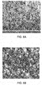
- Fig. 6A shows the scanning electron micrograph (SEM) image of a coating after the EPD process. A1N constituted about 50 volume % of the coating deposited using the EPD process.
- FIG. 6B shows the SEM image of the coating after epoxy-resin back fill. As shown in Fig. 6B , the epoxy resin has infiltrated substantially majority of the voids present in the EPD coating.
- the average alternating current (AC) breakdown strength of the cured coating was greater than 25kV/mm and the average thermal conductivity measured was greater than 0.8 W/m.K.
- Example 2 Electrophoretic deposition of an A1N coating on a Cu coupon by varying the deposition parameters
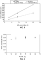
- Fig. 7 shows the weight/area (or thickness of the A1N coating) as a function of the applied field for Samples 1-3 (varying A1N concentration). As shown in Fig. 7 , for all the three samples, the thickness of the AlN coating was linearly proportional to the applied field.
- Fig. 8 shows the thickness of the A1N coating as a function of the A1N concentration using two different deposition voltages (20 Volts and 60 Volts). As shown in Fig. 8 , for both the deposition voltages, the thickness of the A1N coating was linearly proportional to the A1N concentration.
- Fig. 9 shows the thickness of the AlN coating as a function of the PEI/AlN ratio. Therefore, it was observed that the coating thickness is dependent on the AlN concentration rather than the PEI concentration, at the same applied electric field.
- a slurry was prepared as described in Example 1 using 50 g of A1N, 3 mL of PEI in 100 mL of ethanol.
- the slurry was electrophoretically coated on a coupon using the EPD process described above in Example 1 by varying the voltage that was applied for 20s using an electrode gap of 5 mm.
- the coated film did not show any dry film cracking even at the higher concentrations of AlN in the slurry, when PEI/AlN was above 30 ⁇ L/g.
- a slurry formulation was prepared by mixing 50 g of AlN and 2 mL of PEI in 100 mL of ethanol.
- the steel laminate core slots of the statorette were cleaned from any grease followed by rinsing.
- the cleaned slots were then placed in an etchant solution for about 30 seconds. This was followed by distilled water wash and cleanse drying before deposition.
- the cleaned statorette was then contacted with the slurry prepared above and AlN was electrophoretically deposited on the slots using different electrode configurations.
- Fig. 10A shows an electrode configuration in which a plurality of electrodes was placed in individual slots.
- the electrode gap using this configuration was 5 mm, deposition voltage was 40 Volts and deposition time was 60 seconds.
- Fig. 10B shows an electrode configuration in which a single electrode was placed in the stator bore. The electrode gap using this configuration was about 7 mm, deposition voltage was 100 Volts, and deposition time was 120 seconds.
- the AN-coated statorette was placed in a container in an autoclave along with an application of vacuum for 30 minutes. Following the application of the vacuum, epoxy resin was allowed to enter the autoclave from the bottom of the container, until the statorette was fully immersed in the epoxy resin. After complete immersion of the statorette in the epoxy resin, the autoclave was held under vacuum for 30 minutes, followed by application of 100 psi N 2 to the autoclave and holding the autoclave under pressure for ⁇ 1.5 hours. This vacuum and pressure cycle was repeated a few times to ensure that the epoxy resin is fully penetrated into the AlN coating. After taking the statorette out from the autoclave, the excess resin was drained and coating was cured in an oven using the resin curing profile. The uniformity of the coating obtained using the electrode configuration of Fig. 10A was better than the uniformity of the coating obtained using the electrode configuration of Fig. 10B .
- a slurry formulation was prepared by mixing 90 g of AlN, 3600 ⁇ L of PEI (10000 MW branched, 50% in ethanol) in 450 mL of ethanol.
- the slip was prepared by ultrasonicating the mixture with small horn in a 600 ml metal beaker with ice bath cooling and no magnetic stirring for 3 min active sonication time, using an amplitude of 80%.
- the cleaned and primed Hiperco 50TM coupons, as described earlier, were contacted with the slurry prepared above and AlN was electrophoretically deposited on the coupons using an electrode gap of 5 mm, applied voltage of 25 Volts and deposition time of 20 seconds.
- HardsilTM (from Gelest) silicone resin for dip coating was prepared by mixing 99% part A with 1% part B, followed by degassing the mixture under house vacuum at room temperature until bubbles were almost gone.
- the AN-coated coupons were placed in a vacuum oven, and heated to a temperature of 100 °C. A full vacuum of 2 mBar was applied to the coated coupons in the vacuum oven and the coupons were held for 1 hour under vacuum.
- the AlN-coated coupons were lowered into the silicone resin solution at the speed of 100 ⁇ m/min followed by lifting them out of the solution at the speed of 500 ⁇ m/min.
- the silicone resin-impregnated AlN-coated coupons were heated at 150 °C for 6 hours (1 min ramp heating time), and 200 °C for 2 hours (15 min. ramp heating time). This was followed by heating at 250 °C for 2 hours (15 min. ramp heating time) and 5 hours of cooling to room temperature.
- the average alternating current (AC) breakdown strength of the cured coating was greater than 25 kV/
- a slurry formulation was prepared by mixing 90 g of AlN and 5400 ⁇ L of the charging agent in 450 mL of ethanol.
- Two different charging agents from Gelest were used: trimethoxysilylpropyl-modified polyethyleneimine (TMSP-PEI) 56 wt% in in IPA and aminoethylamino/vinyl/silsesquioxane 26 wt% in aqueous solution.
- the slips were prepared by ultrasonicating the mixture with small horn in a 600 ml metal beaker with ice bath cooling and no magnetic stirring for 3 min active sonication time, using an amplitude of 80%.
- HardsilTM (from Gelest) silicone resin for dip coating was prepared by mixing 99% part A with 1% part B, followed by degassing the mixture under house vacuum at room temperature until bubbles were almost gone.
- the AN-coated coupons were placed in a vacuum oven, and heated to a temperature of 100 °C. A full vacuum of 2 mBar was applied to the coated coupons in the vacuum oven and the coupons were held for 1 hour under vacuum.
- the AlN-coated coupons were lowered into the silicone resin solution at the speed of 100 ⁇ m/min followed by lifting them out of the solution at the speed of 500 ⁇ m/min.
- the silicone resin-impregnated AlN-coated coupons were heated at 150 °C for 6 hours (1 min ramp heating time), and 200 °C for 2 hours (15 min. ramp heating time). This was followed by heating at 250 °C for 2 hours (15 min. ramp heating time) and 5 hours of cooling to room temperature.
- the average alternating current (AC) breakdown strength of the cured coating was greater than 25 kV/
- Example 6 Electrophoretic deposition of a boron nitride (BN) coating on Cu and steel coupons followed by silicone resin back-fill
- a slurry formulation was prepared by mixing 13 g of BN, 400 ⁇ L of PEI (10000 MW branched, 50% in ethanol) in 150 mL of ethanol.
- PEI 10000 MW branched, 50% in ethanol
- the thickness of the BN coated on the coupons was about 140 ⁇ m.
- HardsilTM (from Gelest) silicone resin for dip coating was prepared by mixing 99% part A with 1% part B, then degassing the mixture under house vacuum at room temperature until bubbles were almost gone.
- the BN-coated Cu coupons were placed in a vacuum oven, and heated to a temperature of 100 °C. A full vacuum of 2 mBar was applied to the coated coupons in the vacuum oven and the coupons were held for 1 hour under vacuum.
- the BN-coated coupons were lowered into the silicone resin solution at the speed of 100 ⁇ m/min followed by lifting them out of the solution at the speed of 500 ⁇ m/min.
- the silicone resin-impregnated BN-coated coupons were heated at 150 °C for 6 hours (1 min ramp heating time), and 200 °C for 2 hours (15 min. ramp heating time). This was followed by heating at 250 °C for 2 hours (15 min. ramp heating time) and 5 hours of cooling to room temperature.
- the average alternating current (AC) breakdown strength of the cured coating was greater than 60-70 k
Landscapes
- Engineering & Computer Science (AREA)
- Chemical & Material Sciences (AREA)
- Power Engineering (AREA)
- Electrochemistry (AREA)
- Chemical Kinetics & Catalysis (AREA)
- Materials Engineering (AREA)
- Metallurgy (AREA)
- Organic Chemistry (AREA)
- Manufacturing & Machinery (AREA)
- Inorganic Chemistry (AREA)
- Manufacture Of Motors, Generators (AREA)
- Insulation, Fastening Of Motor, Generator Windings (AREA)
- Application Of Or Painting With Fluid Materials (AREA)
Applications Claiming Priority (1)
| Application Number | Priority Date | Filing Date | Title |
|---|---|---|---|
| US15/993,263 US10790731B2 (en) | 2018-05-30 | 2018-05-30 | Methods of depositing coatings on electrical machine components |
Publications (3)
| Publication Number | Publication Date |
|---|---|
| EP3576252A2 true EP3576252A2 (de) | 2019-12-04 |
| EP3576252A3 EP3576252A3 (de) | 2020-03-18 |
| EP3576252B1 EP3576252B1 (de) | 2024-11-27 |
Family
ID=66647343
Family Applications (1)
| Application Number | Title | Priority Date | Filing Date |
|---|---|---|---|
| EP19176613.8A Active EP3576252B1 (de) | 2018-05-30 | 2019-05-24 | Verfahren zum aufbringen von beschichtungen auf elektrische maschinenkomponenten |
Country Status (3)
| Country | Link |
|---|---|
| US (1) | US10790731B2 (de) |
| EP (1) | EP3576252B1 (de) |
| CN (1) | CN110556985B (de) |
Cited By (2)
| Publication number | Priority date | Publication date | Assignee | Title |
|---|---|---|---|---|
| EP4407842A1 (de) * | 2023-01-11 | 2024-07-31 | General Electric Company | Verfahren zur isolierung von leitern in einer elektrischen maschine |
| CN118852978A (zh) * | 2023-04-28 | 2024-10-29 | 比亚迪股份有限公司 | 绝缘电泳涂料、具有绝缘层的工件、电池包和用电设备 |
Families Citing this family (11)
| Publication number | Priority date | Publication date | Assignee | Title |
|---|---|---|---|---|
| US10491071B2 (en) * | 2017-02-16 | 2019-11-26 | General Electric Company | Method of manufacturing an electric machine with a conformal stator coating |
| US11677282B2 (en) * | 2020-02-27 | 2023-06-13 | Accelerated Systems Inc. | Composite material for thermal management in an electric motor |
| US12176125B2 (en) | 2020-07-15 | 2024-12-24 | Ge Aviation Systems Llc | Method of making an insulated conductive component |
| US11551993B2 (en) | 2020-08-28 | 2023-01-10 | Ge Aviation Systems Llc | Power overlay module and method of assembling |
| US12139808B2 (en) * | 2022-01-12 | 2024-11-12 | General Electric Company | Formation of a barrier coating using electrophoretic deposition of a slurry |
| DE102022202880A1 (de) * | 2022-03-24 | 2023-09-28 | Siemens Aktiengesellschaft | Pulverlackformulierung zur Isolation des Wickelkopfes einer elektrischen rotierenden Maschine |
| CN116971012A (zh) * | 2022-11-09 | 2023-10-31 | 陕西重型汽车有限公司 | 一种用于5xxx和6xxx铝合金汽车覆盖件的低压阴极电泳涂装工艺 |
| GB2626777A (en) * | 2023-02-02 | 2024-08-07 | Moog Controls Ltd | Brushless DC motor for use at high temperatures |
| CN117026335A (zh) * | 2023-07-06 | 2023-11-10 | 安徽科蓝特铝业股份有限公司 | 一种新能源车用压铸铝合金及其制备方法 |
| CN120344621A (zh) * | 2023-09-26 | 2025-07-18 | 株式会社力森诺科 | 氮化铝填料、氮化铝填料的制造方法、树脂组合物及树脂组合物的制造方法 |
| CN120683466B (zh) * | 2025-08-20 | 2025-11-14 | 浙江泰峰高压电器有限公司 | 一种用于柜式互感器的高强度复合绝缘材料及柜式互感器 |
Family Cites Families (20)
| Publication number | Priority date | Publication date | Assignee | Title |
|---|---|---|---|---|
| US3926760A (en) | 1973-09-28 | 1975-12-16 | Du Pont | Process for electrophoretic deposition of polymer |
| JPS61281880A (ja) * | 1985-06-07 | 1986-12-12 | Matsushita Electric Ind Co Ltd | 絶縁耐摩耗被覆層を有する物品 |
| JPH01133904A (ja) * | 1987-07-17 | 1989-05-26 | Nisshin Steel Co Ltd | 各種形状の超電導体の作製法 |
| US8441777B2 (en) * | 2009-05-29 | 2013-05-14 | Avx Corporation | Solid electrolytic capacitor with facedown terminations |
| ES2699495T3 (es) | 2011-02-08 | 2019-02-11 | Cambridge Nanotherm Ltd | Sustrato de metal aislado |
| US20130069478A1 (en) | 2011-09-20 | 2013-03-21 | Colin Hamer | Electrical machine with winding conductor having ceramic insulation |
| US8878470B2 (en) | 2011-10-18 | 2014-11-04 | Regal Beloit America, Inc. | Methods and apparatus for reducing size and costs of motor controllers for electric motors |
| CN202663272U (zh) | 2012-05-21 | 2013-01-09 | 常州富兴机电有限公司 | 一种防锈步进电机 |
| US9419502B2 (en) | 2012-08-03 | 2016-08-16 | Hamilton Sundstrand Corporation | Additive manufacturing of a component having a laminated stack of layers |
| US9303327B2 (en) | 2013-01-10 | 2016-04-05 | Infineon Technologies Ag | Electric component with an electrophoretically deposited film |
| US9841195B2 (en) * | 2013-02-28 | 2017-12-12 | Haier Us Appliance Solutions, Inc. | Non-stick, pyrolytic coatings for heating devices |
| US20150076951A1 (en) | 2013-09-16 | 2015-03-19 | Hamilton Sundstrand Corporation | Electric machine construction |
| JP6240779B2 (ja) * | 2013-12-12 | 2017-11-29 | ゼネラル・エレクトリック・カンパニイ | ポリマーゲル下でアブレイダブル皮膜を堆積する方法 |
| US9667112B2 (en) | 2014-08-28 | 2017-05-30 | General Electric Company | Rotor slot liners |
| US20170292029A1 (en) * | 2014-09-19 | 2017-10-12 | Mie University | Electrophoretic deposition fluid, metal core substrate, and method for fabricating the metal core substrate |
| DE102014221939A1 (de) | 2014-10-28 | 2016-04-28 | Robert Bosch Gmbh | Isolierelement für die Statorwicklung einer elektrischen Maschine und eine elektrische Maschine |
| RU2593600C1 (ru) | 2015-06-01 | 2016-08-10 | Федеральное государственное бюджетное образовательное учреждение высшего профессионального образования "Томский государственный университет систем управления и радиоэлектроники" | Способ изолировки пазов магнитных сердечников статоров электродвигателей |
| US20170063183A1 (en) | 2015-08-29 | 2017-03-02 | Abb Technology Ag | Electrical machines and fabrication methods therefor |
| GB2548266B (en) | 2015-11-04 | 2018-06-27 | Payton Planar Magnetics Ltd | Planar transformer components comprising electrophoretically deposited coating |
| US11122715B2 (en) * | 2018-05-11 | 2021-09-14 | General Electric Company | Conformal heat pipe assemblies |
-
2018
- 2018-05-30 US US15/993,263 patent/US10790731B2/en active Active
-
2019
- 2019-05-24 EP EP19176613.8A patent/EP3576252B1/de active Active
- 2019-05-30 CN CN201910463968.0A patent/CN110556985B/zh active Active
Cited By (2)
| Publication number | Priority date | Publication date | Assignee | Title |
|---|---|---|---|---|
| EP4407842A1 (de) * | 2023-01-11 | 2024-07-31 | General Electric Company | Verfahren zur isolierung von leitern in einer elektrischen maschine |
| CN118852978A (zh) * | 2023-04-28 | 2024-10-29 | 比亚迪股份有限公司 | 绝缘电泳涂料、具有绝缘层的工件、电池包和用电设备 |
Also Published As
| Publication number | Publication date |
|---|---|
| CN110556985A (zh) | 2019-12-10 |
| EP3576252A3 (de) | 2020-03-18 |
| US10790731B2 (en) | 2020-09-29 |
| CN110556985B (zh) | 2021-06-11 |
| EP3576252B1 (de) | 2024-11-27 |
| US20190372441A1 (en) | 2019-12-05 |
Similar Documents
| Publication | Publication Date | Title |
|---|---|---|
| EP3576252B1 (de) | Verfahren zum aufbringen von beschichtungen auf elektrische maschinenkomponenten | |
| US20220173630A1 (en) | Electrically insulating, thermally conductive coatings for electrical systems and deposition methods thereof | |
| EP3178095B1 (de) | Hochtemperaturisolierter aluminiumleiter | |
| EP1486997B1 (de) | Herstellungsverfahren der Isolierung einer Spulenwicklung | |
| US8716914B2 (en) | Stator of vehicle AC generator and method for manufacturing the same | |
| JPWO2001016965A1 (ja) | 絶縁材及び電機巻線とその製造法 | |
| GB2150153A (en) | Electrodeposition of mica on coil or bar connections | |
| CZ20022238A3 (cs) | Způsob výroby vysoce kvalitní izolace pro vodiče nebo svazky vodičů | |
| US6780457B2 (en) | Method for producing a high-quality insulation of electrical conductors or conductor bundles of rotating electrical machines by means of fluidized-bed sintering | |
| KR102451355B1 (ko) | 절연층을 도포하기 위한 방법 및 전기 부품 | |
| JP2010158113A (ja) | 電気絶縁部材、回転電機用固定子コイルおよび回転電機 | |
| JP5135532B2 (ja) | 積層モータコア表面の絶縁被膜被覆方法 | |
| Hofmann et al. | Innovative and energy-efficient insulation technology for the production of electric drives | |
| JP4159308B2 (ja) | 車両用回転電機とその製造方法 | |
| Steinacker et al. | Hair Pin motors: possible impregnation and encapsulation techniques, materials and variables to be considered | |
| JP2009187817A (ja) | 絶縁シート、固定子コイルおよび回転電機 | |
| JP2012029399A (ja) | コイルの製造方法及びコイル | |
| CN119517490B (zh) | 漆包线及其制备方法和电机 | |
| Siesing et al. | Electrical isolation of coils in Soft Magnetic Composite applications | |
| EP3402050A1 (de) | Isolierter draht einer spule für einen wildgewickelten stator | |
| RU2593825C1 (ru) | Способ изолировки пазов магнитных сердечников якорей электродвигателей | |
| EP3940120A1 (de) | Verfahren zur herstellung einer isolierten leitenden komponente | |
| JP2022116834A (ja) | コイル製造方法 | |
| WO2025053055A1 (ja) | コイル部材とその製造方法および電機子 | |
| JP2022116835A (ja) | 回転電機用ステータ |
Legal Events
| Date | Code | Title | Description |
|---|---|---|---|
| PUAI | Public reference made under article 153(3) epc to a published international application that has entered the european phase |
Free format text: ORIGINAL CODE: 0009012 |
|
| STAA | Information on the status of an ep patent application or granted ep patent |
Free format text: STATUS: THE APPLICATION HAS BEEN PUBLISHED |
|
| AK | Designated contracting states |
Kind code of ref document: A2 Designated state(s): AL AT BE BG CH CY CZ DE DK EE ES FI FR GB GR HR HU IE IS IT LI LT LU LV MC MK MT NL NO PL PT RO RS SE SI SK SM TR |
|
| AX | Request for extension of the european patent |
Extension state: BA ME |
|
| PUAL | Search report despatched |
Free format text: ORIGINAL CODE: 0009013 |
|
| AK | Designated contracting states |
Kind code of ref document: A3 Designated state(s): AL AT BE BG CH CY CZ DE DK EE ES FI FR GB GR HR HU IE IS IT LI LT LU LV MC MK MT NL NO PL PT RO RS SE SI SK SM TR |
|
| AX | Request for extension of the european patent |
Extension state: BA ME |
|
| RIC1 | Information provided on ipc code assigned before grant |
Ipc: C25D 13/02 20060101ALI20200207BHEP Ipc: C09D 5/44 20060101ALI20200207BHEP Ipc: H02K 15/12 20060101ALI20200207BHEP Ipc: H02K 1/04 20060101AFI20200207BHEP |
|
| STAA | Information on the status of an ep patent application or granted ep patent |
Free format text: STATUS: REQUEST FOR EXAMINATION WAS MADE |
|
| 17P | Request for examination filed |
Effective date: 20200817 |
|
| RBV | Designated contracting states (corrected) |
Designated state(s): AL AT BE BG CH CY CZ DE DK EE ES FI FR GB GR HR HU IE IS IT LI LT LU LV MC MK MT NL NO PL PT RO RS SE SI SK SM TR |
|
| STAA | Information on the status of an ep patent application or granted ep patent |
Free format text: STATUS: EXAMINATION IS IN PROGRESS |
|
| 17Q | First examination report despatched |
Effective date: 20211208 |
|
| GRAP | Despatch of communication of intention to grant a patent |
Free format text: ORIGINAL CODE: EPIDOSNIGR1 |
|
| STAA | Information on the status of an ep patent application or granted ep patent |
Free format text: STATUS: GRANT OF PATENT IS INTENDED |
|
| INTG | Intention to grant announced |
Effective date: 20240603 |
|
| GRAS | Grant fee paid |
Free format text: ORIGINAL CODE: EPIDOSNIGR3 |
|
| GRAA | (expected) grant |
Free format text: ORIGINAL CODE: 0009210 |
|
| STAA | Information on the status of an ep patent application or granted ep patent |
Free format text: STATUS: THE PATENT HAS BEEN GRANTED |
|
| RAP3 | Party data changed (applicant data changed or rights of an application transferred) |
Owner name: GENERAL ELECTRIC COMPANY |
|
| P01 | Opt-out of the competence of the unified patent court (upc) registered |
Free format text: CASE NUMBER: APP_55960/2024 Effective date: 20241011 |
|
| AK | Designated contracting states |
Kind code of ref document: B1 Designated state(s): AL AT BE BG CH CY CZ DE DK EE ES FI FR GB GR HR HU IE IS IT LI LT LU LV MC MK MT NL NO PL PT RO RS SE SI SK SM TR |
|
| REG | Reference to a national code |
Ref country code: GB Ref legal event code: FG4D |
|
| REG | Reference to a national code |
Ref country code: CH Ref legal event code: EP |
|
| REG | Reference to a national code |
Ref country code: IE Ref legal event code: FG4D |
|
| REG | Reference to a national code |
Ref country code: DE Ref legal event code: R096 Ref document number: 602019062477 Country of ref document: DE |
|
| REG | Reference to a national code |
Ref country code: LT Ref legal event code: MG9D |
|
| REG | Reference to a national code |
Ref country code: NL Ref legal event code: MP Effective date: 20241127 |
|
| PG25 | Lapsed in a contracting state [announced via postgrant information from national office to epo] |
Ref country code: PT Free format text: LAPSE BECAUSE OF FAILURE TO SUBMIT A TRANSLATION OF THE DESCRIPTION OR TO PAY THE FEE WITHIN THE PRESCRIBED TIME-LIMIT Effective date: 20250327 Ref country code: HR Free format text: LAPSE BECAUSE OF FAILURE TO SUBMIT A TRANSLATION OF THE DESCRIPTION OR TO PAY THE FEE WITHIN THE PRESCRIBED TIME-LIMIT Effective date: 20241127 Ref country code: IS Free format text: LAPSE BECAUSE OF FAILURE TO SUBMIT A TRANSLATION OF THE DESCRIPTION OR TO PAY THE FEE WITHIN THE PRESCRIBED TIME-LIMIT Effective date: 20250327 |
|
| PG25 | Lapsed in a contracting state [announced via postgrant information from national office to epo] |
Ref country code: FI Free format text: LAPSE BECAUSE OF FAILURE TO SUBMIT A TRANSLATION OF THE DESCRIPTION OR TO PAY THE FEE WITHIN THE PRESCRIBED TIME-LIMIT Effective date: 20241127 Ref country code: NL Free format text: LAPSE BECAUSE OF FAILURE TO SUBMIT A TRANSLATION OF THE DESCRIPTION OR TO PAY THE FEE WITHIN THE PRESCRIBED TIME-LIMIT Effective date: 20241127 |
|
| REG | Reference to a national code |
Ref country code: AT Ref legal event code: MK05 Ref document number: 1746677 Country of ref document: AT Kind code of ref document: T Effective date: 20241127 |
|
| PG25 | Lapsed in a contracting state [announced via postgrant information from national office to epo] |
Ref country code: BG Free format text: LAPSE BECAUSE OF FAILURE TO SUBMIT A TRANSLATION OF THE DESCRIPTION OR TO PAY THE FEE WITHIN THE PRESCRIBED TIME-LIMIT Effective date: 20241127 |
|
| PG25 | Lapsed in a contracting state [announced via postgrant information from national office to epo] |
Ref country code: ES Free format text: LAPSE BECAUSE OF FAILURE TO SUBMIT A TRANSLATION OF THE DESCRIPTION OR TO PAY THE FEE WITHIN THE PRESCRIBED TIME-LIMIT Effective date: 20241127 |
|
| PG25 | Lapsed in a contracting state [announced via postgrant information from national office to epo] |
Ref country code: NO Free format text: LAPSE BECAUSE OF FAILURE TO SUBMIT A TRANSLATION OF THE DESCRIPTION OR TO PAY THE FEE WITHIN THE PRESCRIBED TIME-LIMIT Effective date: 20250227 |
|
| PG25 | Lapsed in a contracting state [announced via postgrant information from national office to epo] |
Ref country code: LV Free format text: LAPSE BECAUSE OF FAILURE TO SUBMIT A TRANSLATION OF THE DESCRIPTION OR TO PAY THE FEE WITHIN THE PRESCRIBED TIME-LIMIT Effective date: 20241127 Ref country code: AT Free format text: LAPSE BECAUSE OF FAILURE TO SUBMIT A TRANSLATION OF THE DESCRIPTION OR TO PAY THE FEE WITHIN THE PRESCRIBED TIME-LIMIT Effective date: 20241127 Ref country code: GR Free format text: LAPSE BECAUSE OF FAILURE TO SUBMIT A TRANSLATION OF THE DESCRIPTION OR TO PAY THE FEE WITHIN THE PRESCRIBED TIME-LIMIT Effective date: 20250228 |
|
| PG25 | Lapsed in a contracting state [announced via postgrant information from national office to epo] |
Ref country code: PL Free format text: LAPSE BECAUSE OF FAILURE TO SUBMIT A TRANSLATION OF THE DESCRIPTION OR TO PAY THE FEE WITHIN THE PRESCRIBED TIME-LIMIT Effective date: 20241127 |
|
| PG25 | Lapsed in a contracting state [announced via postgrant information from national office to epo] |
Ref country code: RS Free format text: LAPSE BECAUSE OF FAILURE TO SUBMIT A TRANSLATION OF THE DESCRIPTION OR TO PAY THE FEE WITHIN THE PRESCRIBED TIME-LIMIT Effective date: 20250227 |
|
| PG25 | Lapsed in a contracting state [announced via postgrant information from national office to epo] |
Ref country code: SM Free format text: LAPSE BECAUSE OF FAILURE TO SUBMIT A TRANSLATION OF THE DESCRIPTION OR TO PAY THE FEE WITHIN THE PRESCRIBED TIME-LIMIT Effective date: 20241127 |
|
| PGFP | Annual fee paid to national office [announced via postgrant information from national office to epo] |
Ref country code: DE Payment date: 20250423 Year of fee payment: 7 |
|
| PG25 | Lapsed in a contracting state [announced via postgrant information from national office to epo] |
Ref country code: DK Free format text: LAPSE BECAUSE OF FAILURE TO SUBMIT A TRANSLATION OF THE DESCRIPTION OR TO PAY THE FEE WITHIN THE PRESCRIBED TIME-LIMIT Effective date: 20241127 |
|
| PGFP | Annual fee paid to national office [announced via postgrant information from national office to epo] |
Ref country code: GB Payment date: 20250423 Year of fee payment: 7 |
|
| PG25 | Lapsed in a contracting state [announced via postgrant information from national office to epo] |
Ref country code: EE Free format text: LAPSE BECAUSE OF FAILURE TO SUBMIT A TRANSLATION OF THE DESCRIPTION OR TO PAY THE FEE WITHIN THE PRESCRIBED TIME-LIMIT Effective date: 20241127 |
|
| PGFP | Annual fee paid to national office [announced via postgrant information from national office to epo] |
Ref country code: FR Payment date: 20250423 Year of fee payment: 7 |
|
| PG25 | Lapsed in a contracting state [announced via postgrant information from national office to epo] |
Ref country code: RO Free format text: LAPSE BECAUSE OF FAILURE TO SUBMIT A TRANSLATION OF THE DESCRIPTION OR TO PAY THE FEE WITHIN THE PRESCRIBED TIME-LIMIT Effective date: 20241127 |
|
| PG25 | Lapsed in a contracting state [announced via postgrant information from national office to epo] |
Ref country code: SK Free format text: LAPSE BECAUSE OF FAILURE TO SUBMIT A TRANSLATION OF THE DESCRIPTION OR TO PAY THE FEE WITHIN THE PRESCRIBED TIME-LIMIT Effective date: 20241127 |
|
| PG25 | Lapsed in a contracting state [announced via postgrant information from national office to epo] |
Ref country code: CZ Free format text: LAPSE BECAUSE OF FAILURE TO SUBMIT A TRANSLATION OF THE DESCRIPTION OR TO PAY THE FEE WITHIN THE PRESCRIBED TIME-LIMIT Effective date: 20241127 |
|
| PG25 | Lapsed in a contracting state [announced via postgrant information from national office to epo] |
Ref country code: IT Free format text: LAPSE BECAUSE OF FAILURE TO SUBMIT A TRANSLATION OF THE DESCRIPTION OR TO PAY THE FEE WITHIN THE PRESCRIBED TIME-LIMIT Effective date: 20241127 |
|
| REG | Reference to a national code |
Ref country code: DE Ref legal event code: R097 Ref document number: 602019062477 Country of ref document: DE |
|
| PG25 | Lapsed in a contracting state [announced via postgrant information from national office to epo] |
Ref country code: SE Free format text: LAPSE BECAUSE OF FAILURE TO SUBMIT A TRANSLATION OF THE DESCRIPTION OR TO PAY THE FEE WITHIN THE PRESCRIBED TIME-LIMIT Effective date: 20241127 |
|
| PLBE | No opposition filed within time limit |
Free format text: ORIGINAL CODE: 0009261 |
|
| STAA | Information on the status of an ep patent application or granted ep patent |
Free format text: STATUS: NO OPPOSITION FILED WITHIN TIME LIMIT |
|
| REG | Reference to a national code |
Ref country code: CH Ref legal event code: L10 Free format text: ST27 STATUS EVENT CODE: U-0-0-L10-L00 (AS PROVIDED BY THE NATIONAL OFFICE) Effective date: 20251008 |
|
| 26N | No opposition filed |
Effective date: 20250828 |
|
| REG | Reference to a national code |
Ref country code: CH Ref legal event code: H13 Free format text: ST27 STATUS EVENT CODE: U-0-0-H10-H13 (AS PROVIDED BY THE NATIONAL OFFICE) Effective date: 20251223 |
|
| PG25 | Lapsed in a contracting state [announced via postgrant information from national office to epo] |
Ref country code: LU Free format text: LAPSE BECAUSE OF NON-PAYMENT OF DUE FEES Effective date: 20250524 |
|
| PG25 | Lapsed in a contracting state [announced via postgrant information from national office to epo] |
Ref country code: CH Free format text: LAPSE BECAUSE OF NON-PAYMENT OF DUE FEES Effective date: 20250531 |
|
| REG | Reference to a national code |
Ref country code: BE Ref legal event code: MM Effective date: 20250531 |
|
| PG25 | Lapsed in a contracting state [announced via postgrant information from national office to epo] |
Ref country code: MC Free format text: LAPSE BECAUSE OF FAILURE TO SUBMIT A TRANSLATION OF THE DESCRIPTION OR TO PAY THE FEE WITHIN THE PRESCRIBED TIME-LIMIT Effective date: 20241127 |
|
| PG25 | Lapsed in a contracting state [announced via postgrant information from national office to epo] |
Ref country code: IE Free format text: LAPSE BECAUSE OF NON-PAYMENT OF DUE FEES Effective date: 20250524 |
|
| PG25 | Lapsed in a contracting state [announced via postgrant information from national office to epo] |
Ref country code: BE Free format text: LAPSE BECAUSE OF NON-PAYMENT OF DUE FEES Effective date: 20250531 |