EP3575921A1 - Liquid cooling device, coolant circulation system and liquid leakage detecting method - Google Patents
Liquid cooling device, coolant circulation system and liquid leakage detecting method Download PDFInfo
- Publication number
- EP3575921A1 EP3575921A1 EP19177273.0A EP19177273A EP3575921A1 EP 3575921 A1 EP3575921 A1 EP 3575921A1 EP 19177273 A EP19177273 A EP 19177273A EP 3575921 A1 EP3575921 A1 EP 3575921A1
- Authority
- EP
- European Patent Office
- Prior art keywords
- detecting probe
- liquid cooling
- conductor
- insulator
- liquid
- Prior art date
- Legal status (The legal status is an assumption and is not a legal conclusion. Google has not performed a legal analysis and makes no representation as to the accuracy of the status listed.)
- Granted
Links
Images






Classifications
-
- G—PHYSICS
- G06—COMPUTING OR CALCULATING; COUNTING
- G06F—ELECTRIC DIGITAL DATA PROCESSING
- G06F1/00—Details not covered by groups G06F3/00 - G06F13/00 and G06F21/00
- G06F1/16—Constructional details or arrangements
- G06F1/20—Cooling means
-
- F—MECHANICAL ENGINEERING; LIGHTING; HEATING; WEAPONS; BLASTING
- F28—HEAT EXCHANGE IN GENERAL
- F28F—DETAILS OF HEAT-EXCHANGE AND HEAT-TRANSFER APPARATUS, OF GENERAL APPLICATION
- F28F27/00—Control arrangements or safety devices specially adapted for heat-exchange or heat-transfer apparatus
-
- G—PHYSICS
- G01—MEASURING; TESTING
- G01M—TESTING STATIC OR DYNAMIC BALANCE OF MACHINES OR STRUCTURES; TESTING OF STRUCTURES OR APPARATUS, NOT OTHERWISE PROVIDED FOR
- G01M3/00—Investigating fluid-tightness of structures
- G01M3/02—Investigating fluid-tightness of structures by using fluid or vacuum
- G01M3/04—Investigating fluid-tightness of structures by using fluid or vacuum by detecting the presence of fluid at the leakage point
- G01M3/16—Investigating fluid-tightness of structures by using fluid or vacuum by detecting the presence of fluid at the leakage point using electric detection means
-
- G—PHYSICS
- G01—MEASURING; TESTING
- G01M—TESTING STATIC OR DYNAMIC BALANCE OF MACHINES OR STRUCTURES; TESTING OF STRUCTURES OR APPARATUS, NOT OTHERWISE PROVIDED FOR
- G01M3/00—Investigating fluid-tightness of structures
- G01M3/02—Investigating fluid-tightness of structures by using fluid or vacuum
- G01M3/04—Investigating fluid-tightness of structures by using fluid or vacuum by detecting the presence of fluid at the leakage point
- G01M3/16—Investigating fluid-tightness of structures by using fluid or vacuum by detecting the presence of fluid at the leakage point using electric detection means
- G01M3/165—Investigating fluid-tightness of structures by using fluid or vacuum by detecting the presence of fluid at the leakage point using electric detection means by means of cables or similar elongated devices, e.g. tapes
-
- G—PHYSICS
- G01—MEASURING; TESTING
- G01M—TESTING STATIC OR DYNAMIC BALANCE OF MACHINES OR STRUCTURES; TESTING OF STRUCTURES OR APPARATUS, NOT OTHERWISE PROVIDED FOR
- G01M3/00—Investigating fluid-tightness of structures
- G01M3/02—Investigating fluid-tightness of structures by using fluid or vacuum
- G01M3/04—Investigating fluid-tightness of structures by using fluid or vacuum by detecting the presence of fluid at the leakage point
- G01M3/16—Investigating fluid-tightness of structures by using fluid or vacuum by detecting the presence of fluid at the leakage point using electric detection means
- G01M3/18—Investigating fluid-tightness of structures by using fluid or vacuum by detecting the presence of fluid at the leakage point using electric detection means for pipes, cables or tubes; for pipe joints or seals; for valves; for welds; for containers, e.g. radiators
- G01M3/183—Investigating fluid-tightness of structures by using fluid or vacuum by detecting the presence of fluid at the leakage point using electric detection means for pipes, cables or tubes; for pipe joints or seals; for valves; for welds; for containers, e.g. radiators for pipe joints or seals
-
- G—PHYSICS
- G01—MEASURING; TESTING
- G01M—TESTING STATIC OR DYNAMIC BALANCE OF MACHINES OR STRUCTURES; TESTING OF STRUCTURES OR APPARATUS, NOT OTHERWISE PROVIDED FOR
- G01M3/00—Investigating fluid-tightness of structures
- G01M3/02—Investigating fluid-tightness of structures by using fluid or vacuum
- G01M3/04—Investigating fluid-tightness of structures by using fluid or vacuum by detecting the presence of fluid at the leakage point
- G01M3/16—Investigating fluid-tightness of structures by using fluid or vacuum by detecting the presence of fluid at the leakage point using electric detection means
- G01M3/18—Investigating fluid-tightness of structures by using fluid or vacuum by detecting the presence of fluid at the leakage point using electric detection means for pipes, cables or tubes; for pipe joints or seals; for valves; for welds; for containers, e.g. radiators
- G01M3/185—Investigating fluid-tightness of structures by using fluid or vacuum by detecting the presence of fluid at the leakage point using electric detection means for pipes, cables or tubes; for pipe joints or seals; for valves; for welds; for containers, e.g. radiators for welds
-
- G—PHYSICS
- G01—MEASURING; TESTING
- G01M—TESTING STATIC OR DYNAMIC BALANCE OF MACHINES OR STRUCTURES; TESTING OF STRUCTURES OR APPARATUS, NOT OTHERWISE PROVIDED FOR
- G01M3/00—Investigating fluid-tightness of structures
- G01M3/02—Investigating fluid-tightness of structures by using fluid or vacuum
- G01M3/04—Investigating fluid-tightness of structures by using fluid or vacuum by detecting the presence of fluid at the leakage point
- G01M3/16—Investigating fluid-tightness of structures by using fluid or vacuum by detecting the presence of fluid at the leakage point using electric detection means
- G01M3/18—Investigating fluid-tightness of structures by using fluid or vacuum by detecting the presence of fluid at the leakage point using electric detection means for pipes, cables or tubes; for pipe joints or seals; for valves; for welds; for containers, e.g. radiators
- G01M3/186—Investigating fluid-tightness of structures by using fluid or vacuum by detecting the presence of fluid at the leakage point using electric detection means for pipes, cables or tubes; for pipe joints or seals; for valves; for welds; for containers, e.g. radiators for containers, e.g. radiators
- G01M3/188—Investigating fluid-tightness of structures by using fluid or vacuum by detecting the presence of fluid at the leakage point using electric detection means for pipes, cables or tubes; for pipe joints or seals; for valves; for welds; for containers, e.g. radiators for containers, e.g. radiators for radiators
-
- H—ELECTRICITY
- H05—ELECTRIC TECHNIQUES NOT OTHERWISE PROVIDED FOR
- H05K—PRINTED CIRCUITS; CASINGS OR CONSTRUCTIONAL DETAILS OF ELECTRIC APPARATUS; MANUFACTURE OF ASSEMBLAGES OF ELECTRICAL COMPONENTS
- H05K7/00—Constructional details common to different types of electric apparatus
- H05K7/20—Modifications to facilitate cooling, ventilating, or heating
- H05K7/20218—Modifications to facilitate cooling, ventilating, or heating using a liquid coolant without phase change in electronic enclosures
- H05K7/20272—Accessories for moving fluid, for expanding fluid, for connecting fluid conduits, for distributing fluid, for removing gas or for preventing leakage, e.g. pumps, tanks or manifolds
-
- H—ELECTRICITY
- H05—ELECTRIC TECHNIQUES NOT OTHERWISE PROVIDED FOR
- H05K—PRINTED CIRCUITS; CASINGS OR CONSTRUCTIONAL DETAILS OF ELECTRIC APPARATUS; MANUFACTURE OF ASSEMBLAGES OF ELECTRICAL COMPONENTS
- H05K7/00—Constructional details common to different types of electric apparatus
- H05K7/20—Modifications to facilitate cooling, ventilating, or heating
- H05K7/20218—Modifications to facilitate cooling, ventilating, or heating using a liquid coolant without phase change in electronic enclosures
- H05K7/20281—Thermal management, e.g. liquid flow control
-
- H—ELECTRICITY
- H10—SEMICONDUCTOR DEVICES; ELECTRIC SOLID-STATE DEVICES NOT OTHERWISE PROVIDED FOR
- H10W—GENERIC PACKAGES, INTERCONNECTIONS, CONNECTORS OR OTHER CONSTRUCTIONAL DETAILS OF DEVICES COVERED BY CLASS H10
- H10W40/00—Arrangements for thermal protection or thermal control
- H10W40/40—Arrangements for thermal protection or thermal control involving heat exchange by flowing fluids
- H10W40/47—Arrangements for thermal protection or thermal control involving heat exchange by flowing fluids by flowing liquids, e.g. forced water cooling
-
- F—MECHANICAL ENGINEERING; LIGHTING; HEATING; WEAPONS; BLASTING
- F28—HEAT EXCHANGE IN GENERAL
- F28F—DETAILS OF HEAT-EXCHANGE AND HEAT-TRANSFER APPARATUS, OF GENERAL APPLICATION
- F28F2265/00—Safety or protection arrangements; Arrangements for preventing malfunction
- F28F2265/16—Safety or protection arrangements; Arrangements for preventing malfunction for preventing leakage
-
- G—PHYSICS
- G06—COMPUTING OR CALCULATING; COUNTING
- G06F—ELECTRIC DIGITAL DATA PROCESSING
- G06F2200/00—Indexing scheme relating to G06F1/04 - G06F1/32
- G06F2200/20—Indexing scheme relating to G06F1/20
- G06F2200/201—Cooling arrangements using cooling fluid
-
- H—ELECTRICITY
- H10—SEMICONDUCTOR DEVICES; ELECTRIC SOLID-STATE DEVICES NOT OTHERWISE PROVIDED FOR
- H10W—GENERIC PACKAGES, INTERCONNECTIONS, CONNECTORS OR OTHER CONSTRUCTIONAL DETAILS OF DEVICES COVERED BY CLASS H10
- H10W40/00—Arrangements for thermal protection or thermal control
- H10W40/20—Arrangements for cooling
- H10W40/25—Arrangements for cooling characterised by their materials
- H10W40/258—Metallic materials
Definitions
- This disclosure relates to a liquid cooling system for an electronic device, particularly to a liquid cooling device, a coolant circulation system and a liquid leakage detecting method.
- heat dissipation means such as air cooling and heat pipes have gradually failed to cope with the heat generated during the operation of central processing units or graphics processing units.
- the protection mechanism of the computer device is activated to reduce the operating frequency of the central processing unit, the graphics processing unit and even the memory.
- a liquid cooling system is able to quickly remove a large amount of heat, and is used as effective heat dissipation means.
- a liquid cooling conductor (as known as water cooled head), it should have a chamber inside for the circulation of coolant, and is at least partially made of a high thermally-conductive metal. Therefore, the liquid cooling conductor is formed by connecting at least two assemblies, and a seam is formed between the two assemblies. The seam will leak liquid after the sealant is deteriorated, regardless of whether watertight treatment is performed or not.
- the coolant in the chamber needs to be circulated continuously between the chamber and a reservoir to ensure that the coolant in the chamber remains cold.
- the pipe joint connecting the chamber also forms another possible leak point.
- the coolant is typically based on reverse osmosis pure water and provided with appropriate additives. Whether the coolant is pure water or contains additives, it still has certain conductivity even its resistance is high. Once the liquid leaks and flows to the circuit around the chip, a short circuit is caused to damage the computer device. However, the liquid leakage phenomenon occurs inside a computer case, and often cannot be found in time to stop the computer host to avoid the short circuit. Even a liquid pump that provides the liquid cooling cycle is still in operation after the liquid leaks, so that the liquid leakage accelerates and aggravates, and the liquid leakage phenomenon is more difficult to discover in time.
- This disclosure provides a liquid cooling device, a coolant circulation system and a liquid leakage detecting method, which can detect liquid leakage and generate a liquid leakage alarm signal forthwith to shut down the operation of necessary components.
- the liquid cooling conductor includes a chamber defined therein for communicating with outside, the chamber is configured to accommodate a coolant, and the surface of the liquid cooling conductor is provided with at least one communicating port communicating with the chamber; wherein the liquid cooling conductor is formed by joining at least two combination blocks, and at least one of the at least two combination blocks is a metal conductor.
- the detecting probe is disposed on the liquid cooling conductor and normally electrically disconnected from the metal conductor.
- the determining circuit is electrically connected to the metal conductor and the detecting probe, and generates a liquid leakage alarm signal when the metal conductor and the detecting probe are electrically connected.
- a seam is formed between the at least two combination blocks, and the detecting probe is disposed beside the seam; or the detecting probe surrounds the at least one communicating port.
- one of the at least two combination blocks is a metal conductor
- the other combination block is an insulator
- the detecting probe is disposed on the insulator without contacting the metal conductor; or the at least two combination blocks are metal conductors
- the liquid cooling device further comprises an insulating patch attached to the metal conductor, and the detecting probe is attached to the insulating patch.
- the liquid cooling device further includes a sealing member surrounding the seam or the communicating port and located inside the detecting probe.
- the liquid cooling device further includes another sealing member surrounding the seam or the communicating port and located outside the detecting probe.
- the another sealing member is a conductive rubber ring.
- the conductive rubber ring is electrically connected to the detecting probe.
- the liquid cooling device further includes a capillary structure, disposed between the detecting probe and the sealing member.
- the capillary structure is made of absorbent material.
- the capillary structure is surface structure formed on a surface of the insulator.
- the surface structure covers the surface of the insulator excepting the part disposing the sealing member.
- the surface structure is hairline texture, and at least includes two sets of directional interleaving hairlines.
- the detecting probe is attached on the surface structure.
- the capillary structure includes absorbent material and a surface structure formed on a surface of the insulator.
- the detecting probe is configured into a capillary structure, and the detecting probe covers the surface of the insulator excepting the part disposing the sealing member.
- the liquid cooling conductor is formed by joining at least three combination blocks, and the three combination blocks comprise at least one metal conductor, a first insulator and a second insulator;
- the first insulator includes a through hole and a first trough, the first trough is located on a first side of the first insulator, and the through hole communicates with the first trough and a second side of the first insulator;
- the second insulator is joined to the first side of the first insulator to cover the first trough; and the metal conductor is joined to the second side of the first insulator to cover the through hole, so that the first trough and the through hole are sealed to form the chamber.
- a second trough is formed on a side of the second insulator facing the first trough to increase the volume of the chamber.
- the communicating port extends from the outer surface of the second insulator to the second trough and communicates with the chamber through the second trough; or the communicating port penetrates the solid portions of the first insulator and the second insulator from the outer surface of the second insulator to be communicated to the second side of the first insulator.
- the metal conductor further comprises a third trough
- the metal conductor is joined to the second side of the first insulator, and the third trough faces the through hole.
- This disclosure provides also provides a coolant circulation system, comprising the liquid cooling device, a liquid pump, and driving circuit.
- the liquid pump is connected to the at least one communicating port by a pipe.
- the driving circuit is electrically connected to the liquid pump and the determining circuit for driving the liquid pump, and shutting down the liquid pump when receiving the liquid leakage alarm signal from the determining circuit.
- the coolant circulation system further comprises a reservoir, wherein the liquid pump is connected to the communicating port and the reservoir by the pipe.
- the coolant circulation system further comprises an alarm electrically connected to the determining circuit, and the alarm receives the liquid leakage alarm signal to generate a corresponding alarm message.
- This disclosure provides also provides a liquid leakage detecting method, comprising: disposing a detecting probe beside a seam, or disposing the detecting probe around at least one communicating port, wherein the seam is formed on a liquid cooling conductor by joining at least two combination blocks, and the at least one communicating port communicates with the interior of the liquid cooling conductor; providing a first detecting potential for the detecting probe, and providing a second detecting potential for a metal conductor on the liquid cooling conductor; and determining whether the detecting probe and the metal conductor are electrically connected, and generating a liquid leakage alarm signal when the detecting probe and the metal conductor are electrically connected.
- the step of disposing a detecting probe beside a seam comprises: disposing the detecting probe at an insulator portion of the liquid cooling conductor.
- the detecting probe and the metal conductor of the liquid cooling conductor are used as liquid leakage probes, and a relatively simple trigger circuit can be used as the determining circuit, so that the liquid leakage alarm function can be integrated into a portion of the existing liquid cooling device, without a complicated detecting system or changing of the structure of the liquid cooling conductor.
- the liquid leakage alarm signal can be used for shutting down the liquid pump in real time to avoid the continuous occurrence of leakage from destroying surrounding electronic components, and real-time intervention of a user is not required, so that this disclosure has a liquid leakage protection function.
- the liquid cooling device 100 is configured to contact a heat source and provide a coolant to circulate inside the liquid cooling device 100, so as to cool the heat source quickly.
- the heat source may be, but not limited to, a high-power electronic chip such as a central processing unit (CPU) or a graphics processing unit (GPU).
- the liquid cooling device 100 includes at least one liquid cooling conductor 110, a detecting probe 120, and a determining circuit 130.
- the liquid cooling conductor 110 includes a chamber 110a defined therein for communicating with the outside, so as to allow an external coolant to flow therein and accommodate the coolant.
- the liquid cooling conductor 110 is generally formed by joining two or more combination blocks to form the chamber 110a.
- at least one of the combination blocks is a metal conductor 112 for contacting the heat source to rapidly transfer the heat generated by the heat source to the coolant in the chamber 110a.
- one combination block is a metal conductor 112
- the other combination block is an insulator 114, such as a container-like structural member made of acrylic.
- a seam 110b is formed between two combination blocks in the liquid cooling conductor 110 formed by joining the at least two combination blocks.
- the seam 110b may cause leakage to damage surrounding circuits.
- the coolant flowing in the chamber 110a is continuously circulated and exchanged with an external cooler or cooling water tank. Therefore, the surface of the liquid cooling conductor 110 is further provided with one or more communicating ports 110c communicating with the chamber 110a such that the chamber 110a is connected to a circulation device 200 by a pipe 230 (see FIG. 7 ).
- the surface of the liquid cooling conductor 110 is provided with two communicating ports 110c communicating with the chamber 110a, one of the communicating ports 110c is configured for the coolant to flow from a reservoir 210 such as a cooler or a cooling water tank to the chamber 110a, and the other communicating port 110c is configured for the coolant absorbing the heat to leave the chamber 110a and return to the reservoir 210 for cooling.
- a seam 110b that may leak liquid is also formed around the communicating port 110c.
- the detecting probe 120 is disposed on the liquid cooling conductor 110, and is normally electrically disconnected from the metal conductor 112.
- the other combination block is an insulator 114.
- the detecting probe 120 can be directly disposed on the insulator 114 without contact the metal conductor 112, so that the detecting probe 120 can be normally electrically disconnected from the metal conductor 112.
- the insulator 114 of the liquid cooling conductor 110 has a trough machined by turn-milling, such that the insulator 114 is a container-like member.
- the metal conductor 112 is a plate, and can seal the trough to form the chamber 110a.
- the metal conductor 112 partially covers the surface of the insulator 114.
- the detecting probe 120 is ideally disposed on the surface of the insulator 114, and surrounds the metal conductor 112 but does not contact the metal conductor 112, for example, the detecting probe 120 is disposed in parallel beside the seam 110b.
- the seam 110b is located at the edge of the metal conductor 112, regardless of the arrangement direction of the liquid cooling conductor 110 (the arrangement direction of the liquid cooling conductor 110 meets the requirement of contact between the metal conductor 112 and the heat source), and the leaking coolant can flow outward and contact the detecting probe 120, so that the detecting probe 120 is electrically connected to the metal conductor 112 through the coolant.
- the determining circuit 130 is electrically connected to the metal conductor 112 and the detecting probe 120 for generating a liquid leakage alarm signal when the metal conductor 112 and the detecting probe 120 are electrically connected.
- the determining circuit 130 applies a potential difference to the detecting probe 120 and the metal conductor 112, for example, a first detecting potential VI is applied to the detecting probe 120, the metal conductor 112 is electrically grounded as a second detecting potential V2, and a potential difference of subtracting V2 from VI is thus formed.
- the determining circuit 130 determines whether current is generated between the detecting probe 120 and the metal conductor 112.
- the coolant normally contacts the metal conductor 112 in the chamber 110a.
- the detecting probe 120 and the metal conductor 112 are electrically connected through the leaking coolant to generate current, thereby triggering the determining circuit 130 to generate a liquid leakage alarm signal.
- the circuit shown in FIG. 3 is one of the implementations of current detection, but the detecting means for determining whether the electrode 120 and the metal conductor 112 are electrically connected is not limited to the disclosure of FIG. 3 .
- a seam 110b that may leak liquid is also formed around the communicating port 110c. Therefore, in the first embodiment, another detecting probe 120 is disposed on the combination block to surround at least one communicating port 110c. If the seam 110b around the communicating port 110c leaks coolant, the detecting probe 120 and the metal conductor 112 are also conducted to trigger the determining circuit 130 to generate a liquid leakage alarm signal.
- the combination blocks of the liquid cooling conductor 110 are all metal conductors 112.
- the liquid cooling device 100 further includes an insulating patch 140 attached to one of the metal conductors 112, and the detecting probe 120 is attached to the insulating patch 140, so that the detecting probe 120 is disposed on the liquid cooling conductor 110 and normally electrically disconnected from the metal conductor 112 through the insulating patch 140.
- FIG. 6 which shows a liquid cooling device 100 according to a third embodiment of this disclosure.
- the liquid cooling device 100 according to the third embodiment also includes at least one liquid cooling conductor 110, a detecting probe 120 and a determining circuit 130.
- the detecting probe 120 does not need to continuously extend to surround the liquid cooling conductor 110.
- the leaking coolant usually flows downward with gravity.
- the detecting probe 120 is ideally located below the seam 110b, and is as close as possible to the seam 110b without surrounding to immediately contact the coolant as liquid leaks. That is, at least partial detecting probe 120 is located below the seam 110b in the direction of gravity.
- the electrical conductivity of tap water is generally about 350 ⁇ S/cm, the electrical conductivity of reverse osmosis pure water is only 10 ⁇ S/cm.
- the electrical conductivity of the coolant regulated with additives and water may increase or decrease. Weak current or voltage conducted by the coolant under low electrical conductivity can be detected after moderate signal amplification.
- the distance between the detecting probe 120 and the seam 110b also needs to be shortened to shorten the conductive path between the detecting probe 120 and the metal conductor 112 to increase the current when conducting, so as to simplify the requirement of the determining circuit 130 for sensitivity to the detection of a conductive state.
- a fourth embodiment of this disclosure provides a coolant circulation system, including the liquid cooling device 100 as proposed in the foregoing embodiments and a circulation device 200.
- the liquid cooling device 100 includes a liquid cooling conductor 110, a detecting probe 120 and a determining circuit 130, the structure and the connection relationship of which are as described in the foregoing embodiments, and omitted here.
- the circulation device 200 includes a reservoir 210, a liquid pump 220, a pipe 230, and a driving circuit 240.
- the liquid pump 220 is connected to the communicating port 110c and the reservoir 210 by the pipe 230 to pump the coolant to circulate between the chamber 110a of the liquid cooling conductor 110 and the reservoir 210.
- the driving circuit 240 is electrically connected to the liquid pump 220 and the determining circuit 130 of the liquid cooling heat conducting device 100.
- the driving circuit 240 is configured to provide driving power to drive the liquid pump 220 to pump the coolant, and the driving circuit 240 shuts down the liquid pump 220 when receiving the liquid leakage alarm signal to stop pumping the coolant so as to avoid continuous liquid leakage.
- the foregoing driving circuit 240 may be an independent circuit, directly gets power by a power supply of a computer host, and directly receives the liquid leakage alarm signal of the determining circuit 130 by a pin.
- the driving circuit 240 and the determining circuit 130 may also be bridged by an embedded board controller (EBC) of a computer motherboard; in this case, the liquid leakage alarm signal can be further transmitted to the motherboard in addition to the driving circuit 240, to generate alarm information by using a built-in function of an operating system or a loaded monitoring program to inform the user.
- EBC embedded board controller
- the driving circuit 240 and the determining circuit 130 may also be partially or completely integrated into the embedded controller as a part of the motherboard.
- the liquid cooling device 100 may further include an alarm 150, such as an indicator light device or an alarm sound device, electrically connected to the determining circuit 130.
- an alarm 150 such as an indicator light device or an alarm sound device, electrically connected to the determining circuit 130.
- the alarm 150 can receive the liquid leakage alarm signal to generate corresponding alarm message, for example, the indicator light device emits indication light or the alarm sound device emits an alarm sound.
- the liquid cooling device 100 includes at least one liquid cooling conductor 110, a detecting probe 120, and a sealing member 160.
- the liquid cooling conductor 110 is formed by joining three combination blocks.
- the three combination blocks include at least one metal conductor 112, a first insulator 111 and a second insulator 113.
- the first insulator 111 is substantially a plate having one or more through holes 111a and a first trough 111b.
- the first trough 111b is located on a first side of the first insulator 111, and the through hole 111a communicates with the first side and a second side of the first insulator 111.
- the second insulator 113 is joined to the first side of the first insulator 111 to cover the first trough 111b, and the through hole 111a communicates with the first trough 111b and the second side of the first insulator 111.
- the metal conductor 112 is joined to the second side of the first insulator 111 to cover the through hole 111a, so that the first trough 111b and the through hole 111a are sealed into a chamber 110a, and the coolant circulated in the chamber 110a can contact the metal conductor 112.
- the side of the second insulator 113 facing the first trough 111b may also be provided with a second trough 113a that is in the same projection shape as or is slightly larger than the first trough 111b, to increase the volume of the chamber 110a.
- the first trough 111b and the second trough 113a are U-shaped, and the two through holes 111a are respectively disposed corresponding to two ends of the U-shaped openings, so that the coolant flowing through the two through holes 111a can be sufficiently circulated to different portions of the U-shaped chamber 110a. Therefore, the chamber 110a includes the through hole 111a, the first trough 111b and the second trough 113a that communicate with each other. Or, it may also provide only the first trough 111b or the second trough 113a to form the chamber 110a separately.
- the metal conductor 112 is generally a metal plate, and is smaller than the second side of the first insulator 111 in area.
- the metal conductor 112 further includes a third trough 112a.
- the metal conductor 112 is joined to the second side of the first insulator 111, and the third trough 112a faces the through holes 111a.
- the third trough 112a can be used to increase the volume of the chamber 110a.
- the second insulator 113 may be disposed at the communicating port 110c communicating with the chamber 110a.
- the communicating port 110c is configured for connecting the chamber 110a to the circulation device 200 by a pipe 230 (see FIG. 7 ).
- the communicating port 110c may extend from the outer surface of the second insulator 113 to the second trough 113a, and communicate with the chamber 110a through the second trough 113a.
- the communicating port 110c may also penetrate the solid portion of the second insulator 113 through the outer surface of the second insulator 113, and further penetrate the solid portion of the first insulator 111 to communicate with the third trough 112a of the metal conductor 112 and then communicate with the chamber 110a.
- the second side of the first insulator 111 may further be provided with a fourth trough 111c corresponding to the communicating port 110c to extend the volume of the chamber 110a.
- the detecting probe 120 is disposed on the liquid cooling conductor 110, and is normally electrically disconnected from the metal conductor 112.
- the first insulator 111 and the second insulator 113 are electrically insulated, and form a seam 110b along the boundary of the chamber 110a. Therefore, the detecting probe 120 may be disposed on the first insulator 111 or the second insulator 113 so as not to be in contact with the metal conductor 112, and the detecting probe 120 is normally electrically disconnected from the metal conductor 112.
- the detecting probe 120 is disposed on the first insulator 111 or the second insulator 113, surrounds the boundary of the second trough 113a, and is located outside the seam 110b. Substantially, each section of the detecting probe 120 is disposed in parallel beside the seam 110b.
- FIG. 11 shows an example in which the detecting probe 120 is disposed on the first insulator 111 (on the side of the first insulator 111 having the first trough 111b).
- the detecting probe 120 may be fabricated by printing a conductive paint and extends to form a wire segment 122.
- the wire segment 122 extends to a position that is not covered by the first insulator 111, e.g., the outer surface of the first insulator 111, to be exposed and thus can be connected to a supply source of the first detecting potential V1.
- the sealing member 160 may be a rubber ring or a soft annular patch, the shape of which is substantially the same as the projection shape of the detecting probe 120 or the seam 110b, but the size is slightly larger than the projection of the seam 110b and slightly smaller than the detecting probe 120.
- the sealing member 160 surrounds the seam 110b and is located inside the detecting probe 120, i.e., between the detecting probe 120 and the seam 110b.
- the first insulator 111 or the second insulator 113 may be provided with a groove corresponding to the rubber ring, so that the rubber ring is temporarily fixed to the first insulator 111 or the second insulator 113.
- the sealing member 160 is configured to seal the joint interface of the first insulator 111 or the second insulator 113 to further seal the seam 110b, so as to prevent the seam 110b from leaking the coolant.
- the sealing member 160 is aged and coolant leaks through the sealing member 160, the leaking coolant contacts the detecting probe 120 at first, so that the detecting probe 120 is electrically connected to the metal conductor 112 via the coolant.
- the liquid leakage alarm is immediately generated, and the operation of the circulation device 200 is stopped, thereby avoiding the damage of liquid leakage to the computer system.
- a seam 110b that may leak liquid is also formed around the communicating port 110c. Therefore, the detecting probe 120 may also surround the communicating port 110c. Similarly, a sealing member 160 surrounding the seam 110b is also disposed between the seam 110b around the communicating port 110c and the detecting probe 120.
- the communicating port 110c penetrates the joint interface of the first insulator 111 or the second insulator 113, the communicating port 110c actually become a part of the chamber 110a, and the edge of the communicating port 110c passes through the joint interface to form the seam 110b.
- the sealing member 160 is located inside the detecting probe 120 to seal the seam 110b around the communicating port 110c, so as to avoid leakage of the coolant around the communicating port 110c. If liquid leakage occurs, the detecting probe 120 and the metal conductor 112 are also electrically connected to trigger the determining circuit 130 to generate a liquid leakage alarm. As described above, if the first insulator 111 or the second insulator 113 is replaced with the metal conductor 112, the metal conductor 112 and the detecting probe 120 can be isolated by an insulating patch 140, so that the detecting probe 120 can be normally electrically disconnected from the metal conductor 112 by the insulating patch 140.
- FIG. 12 which is another top view of the first insulator 111 according to the fifth embodiment of this disclosure.
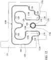
- FIG. 12 of the fifth embodiment is substantially the same as the fourth embodiment except that the detecting probe 120 does not continuously extend around the liquid cooling conductor 110 by a circle.
- the detecting probe 120 is partially disposed under the seam 110b and is as close as possible to the seam 110b. That is, the detecting probe 120 is partially located below the seam 110b in the direction of gravity.
- the sealing member 160 still surrounds the seam 110b and passes between the detecting probe 120 and the seam 110b.
- the liquid cooling device 100 includes at least one liquid cooling conductor 110, a detecting probe 120, and a plurality of sealing members 160.
- the sixth embodiment is substantially the same as the fifth embodiment, and the differences are described below.
- the detecting probe 120 can detect the liquid leakage state immediately, and meanwhile, the sealing member 160 on the outer ring can be used as a backup means to prevent the leaking coolant from continuing to flow out.
- the detecting probe 120 according to the sixth embodiment of this disclosure can also be modified to discontinuously extend and not surround the liquid cooling conductor 110. That is, the detecting probe 120 is partially disposed under the seam 110b and located between two sealing members 160.
- the liquid cooling device 100 includes at least one liquid cooling conductor 110, a detecting probe 120, and a plurality of sealing members 160, 160a.
- the seventh embodiment is substantially the same as sixth embodiment, and the differences are described below.
- At least one sealing member 160a is a conductive rubber ring, and is electrically connected to the detecting probe 120 or connected to the same detecting circuit together with the detecting probe 120.
- the conductive rubber ring as the sealing member 160a may be located outside the detecting probe 120. After the sealing member 160 on the inner ring is aged, the detecting probe 120 can detect the liquid leakage state immediately, and meanwhile, the sealing member 160a on the outer ring can be used as a backup sealing means to prevent the leaking coolant from continuing to flow out.
- the sealing member 160a on the outer ring is also a backup detecting means to avoid the failure of the detecting probe 120 due to various factors (e.g., poor conductivity caused by surface oxidation).
- the detecting probe 120 according to the seventh embodiment can also be modified to discontinuously extend and not surround the liquid cooling conductor 110. That is, the detecting probe 120 is partially disposed under the seam 110b and located between two sealing members 160, 160a.
- the liquid cooling device100 includes at least one liquid cooling conductor 110, a detecting probe 120, a sealing member 160, and a capillary structure 170.
- the eighth embodiment is substantially the same as fifth embodiment, and the differences are described below.
- the detecting probe 120 is spaced from the sealing member 160.
- the capillary structure 170 is disposed between the detecting probe 120 and the sealing member 16.
- the detecting probe120 is disposed around the sealing member 160 and the seam110b, and the capillary structure 170 is also disposed around the sealing member 160 and the seam110b. If the detecting probe 120 is partially disposed as shown in FIG. 12 , the capillary structure 170 can be also partially disposed, and the length of the capillary structure 170 is approximately equaled to the length of the detecting probe 120.
- the capillary structure 170 can be made of absorbent material, such as foam, sponge, fiber sheet, porous material.
- absorbent material such as foam, sponge, fiber sheet, porous material.
- the sealing member 160 is aged and the coolant leaks through the sealing member 160, the coolant would be immediately absorbed by the capillary structure 170.
- At least partial section of the capillary structure 170 would be wetted completely by the coolant, so as to prevent the leaking coolant from forming a droplet due to cohesive force to cut off the connection with the coolant in the chamber 110a.
- the completely wetted capillary structure 170 contacts the detecting probe120, such that detecting probe 120 and the metal conductor 112 are electrically connected through the coolant.
- the liquid leakage alarm is immediately generated, and the operation of the circulation device 200 is stopped, thereby avoiding the damage of liquid leakage to the computer system.
- the capillary structure 170 is a surface structure formed on surface of the insulator (the first insulator 111 or the second insulator 113.
- the surface structure included a plurality of micro grooves extending from the sealing member 160 to the detecting probe 120. The surface structure would be wetted completely by the coolant, so as to prevent the leaking coolant from forming a droplet due to cohesive force to cut off the connection with the coolant in the chamber 110a.
- the sealing member 160 is directly attached on the insulator (the surface of the first insulator 111 or the second insulator 113) or embedded into the groove on the surface of the insulator, the sealing member 160 will protrude on the surface of the insulator, and must has a height higher than the height of the surface structure.
- the height of the sealing member 160 is still higher than that of the surface structure, so as to prevent from being unable to be compressed due to a high surface structure.
- the capillary structure 170 includes an absorbent material 170a and a surface structure 170b formed on a surface of the insulator, for example, a plurality micro grooves disposed beside the sealing member 160 and a sponge disposed beside the detecting probe120, so as to lead the leaking coolant to contact the detecting probe 120.
- the capillary structure 170 is a surface structure formed on the surface of the (the first insulator 111 or the second insulator 113), and covers the surface of the insulator excepting the part disposing the sealing member 160.
- the surface structure is hairline texture formed by hairline surfaced treatment.
- the hairline texture at least includes two sets of directional interleaving hairlines, so as to make leaking coolant diffusing on the surface structure well.
- the detecting probe 120 may be directly attached on the surface structure, and contact or be spaced from the sealing member 160.
- the surface structure occupies most of the surface of the insulator (the insulator 111 or the second insulator 113) instead of being disposed within the narrow gap of the sealing member 160 and the detecting probe 120.
- the surface structure occupying large area of the surface can reduce treatment difficulty and tolerance in assembly. Meanwhile surface structure occupying large area of the surface can absorb more leaking coolant to prevent the leaking coolant from dropping down.
- the detecting probe 120 is disposed on the surface of the insulator (the first insulator 111 or the second insulator 113), and covers the surface of the insulator excepting the part disposing the sealing member 160. Meanwhile, the detecting probe 120 is configured in to capillary structure. For example, graphite is printed on the surface of the insulator by screen printing, to form the detecting probe 120.
- the detecting probe 120 itself is the capillary structure to absorb the leaking coolant well, so as to prevent the leaking coolant from forming a droplet due to cohesive force to cut off the connection with the coolant in the chamber 110a. Providing that the detecting probe 120 is a capillary structure occupying large area of the surface, the manufacturing process of the detecting probe 120 can be simplified, and the detecting probe 120 can absorb the leaking coolant well.
- this disclosure further provides a liquid leakage detecting method for a liquid cooling conductor 110, including the following steps.
- a detecting probe 120 is provided, and the detecting probe 120 is disposed beside a seam 110b or disposed around at least one communicating port 110c, wherein the seam 110b is formed on a liquid cooling conductor 110 by joining at least two combination blocks, and the communicating port 110c communicates with the interior of the liquid cooling conductor 110.
- the liquid cooling conductor 110 is not limited to being formed by joining two combination blocks, and may be formed by joining three combination blocks as in Embodiments 5 to 7.
- the detecting probe 120 needs to be normally electrically insulated from a metal conductor 112 of the liquid cooling conductor 110. If the liquid cooling conductor 110 includes an insulator 114 portion, the detecting probe 120 is disposed on the insulator 114. If the liquid cooling conductor 110 is entirely composed of the metal conductor 112, or the detecting probe 120 needs to be disposed on the metal conductor 112 such that the detecting probe 120 is located below the seam 110b in the direction of gravity, an insulating patch 140 is first attached to the metal conductor 112, and then the detecting probe 120 is attached to the insulating patch 140. Further, as in Embodiment 5, a sealing member 160 may be provided, which surrounds the seam 110b or the communicating port 110c, and is located inside the detecting probe 120.
- another sealing member 160, 160a is provided, which surrounds the seam 110b or the communicating port 110c, and is located outside the detecting probe 120.
- the another sealing member 160, 160a can be replaced with a conductive rubber ring as a backup means of the detecting probe 120.
- a first detecting potential VI is provided for the detecting probe 120, and a second detecting potential V2 is provided for the metal conductor 112.
- the second detecting potential V2 may be a ground potential. That is, the metal conductor 112 is grounded.
- the first detecting potential VI is also provided for the conductive rubber ring.
- the first detecting potential VI is provided for the conductive rubber ring by means of directly communicating the detecting probe 120 with a line; for example, the detecting probe 120 is fabricated by printing a conductive paint and extends to form a wire segment 122, and the conductive rubber ring contacts the wire segment 122.
- a separate wire segment 122 is fabricated by printing a conductive paint, the conductive rubber ring contacts the wire segment 122, and the wire segment 122 is connected to a supply source of the first detecting potential V1.
- Step 130 whether the detecting probe 120 and the metal conductor 112 are conducted is judged by measuring the current between the detecting probe 120 and the metal conductor 112 or by other detecting means.
- Step 140 when the detecting probe 120 and the metal conductor 112 are conducted, a liquid leakage alarm signal is generated to drive an alarm 150 to shut down a liquid pump 220, or is sent to the motherboard to warn the user through an operating system.
- the detecting probe 120 and the metal conductor 112 of the liquid cooling conductor 110 are used as liquid leakage probes, and a relatively simple trigger circuit can be used as the determining circuit 130, so that the liquid leakage alarm function can be integrated into a part of the existing liquid cooling device 100, without a complicated detecting system or changing of the structure of the liquid cooling conductor 110.
- the liquid leakage alarm signal can be used for shutting down the liquid pump 220 in real time to avoid the continuous occurrence of leakage from destroying surrounding electronic components, and real-time intervention of a user is not required, so that this disclosure has a liquid leakage protection function.
Landscapes
- Engineering & Computer Science (AREA)
- Physics & Mathematics (AREA)
- Microelectronics & Electronic Packaging (AREA)
- General Physics & Mathematics (AREA)
- Thermal Sciences (AREA)
- General Engineering & Computer Science (AREA)
- Theoretical Computer Science (AREA)
- Mechanical Engineering (AREA)
- Human Computer Interaction (AREA)
- Cooling Or The Like Of Semiconductors Or Solid State Devices (AREA)
- Cooling Or The Like Of Electrical Apparatus (AREA)
- Examining Or Testing Airtightness (AREA)
Abstract
Description
- This disclosure relates to a liquid cooling system for an electronic device, particularly to a liquid cooling device, a coolant circulation system and a liquid leakage detecting method.
- As the power consumption of computer chips is increasingly high, heat dissipation means such as air cooling and heat pipes have gradually failed to cope with the heat generated during the operation of central processing units or graphics processing units. Especially for an over-clocking computer, if the heat is not effectively dissipated, the protection mechanism of the computer device is activated to reduce the operating frequency of the central processing unit, the graphics processing unit and even the memory.
- A liquid cooling system is able to quickly remove a large amount of heat, and is used as effective heat dissipation means. For a liquid cooling conductor (as known as water cooled head), it should have a chamber inside for the circulation of coolant, and is at least partially made of a high thermally-conductive metal. Therefore, the liquid cooling conductor is formed by connecting at least two assemblies, and a seam is formed between the two assemblies. The seam will leak liquid after the sealant is deteriorated, regardless of whether watertight treatment is performed or not. In addition, the coolant in the chamber needs to be circulated continuously between the chamber and a reservoir to ensure that the coolant in the chamber remains cold. The pipe joint connecting the chamber also forms another possible leak point.
- The coolant is typically based on reverse osmosis pure water and provided with appropriate additives. Whether the coolant is pure water or contains additives, it still has certain conductivity even its resistance is high. Once the liquid leaks and flows to the circuit around the chip, a short circuit is caused to damage the computer device. However, the liquid leakage phenomenon occurs inside a computer case, and often cannot be found in time to stop the computer host to avoid the short circuit. Even a liquid pump that provides the liquid cooling cycle is still in operation after the liquid leaks, so that the liquid leakage accelerates and aggravates, and the liquid leakage phenomenon is more difficult to discover in time.
- This disclosure provides a liquid cooling device, a coolant circulation system and a liquid leakage detecting method, which can detect liquid leakage and generate a liquid leakage alarm signal forthwith to shut down the operation of necessary components.
- This disclosure provides a liquid cooling device comprising a liquid cooling conductor, a detecting probe, and a determining circuit. The liquid cooling conductor includes a chamber defined therein for communicating with outside, the chamber is configured to accommodate a coolant, and the surface of the liquid cooling conductor is provided with at least one communicating port communicating with the chamber; wherein the liquid cooling conductor is formed by joining at least two combination blocks, and at least one of the at least two combination blocks is a metal conductor. The detecting probe is disposed on the liquid cooling conductor and normally electrically disconnected from the metal conductor. The determining circuit is electrically connected to the metal conductor and the detecting probe, and generates a liquid leakage alarm signal when the metal conductor and the detecting probe are electrically connected.
- In one or more embodiments, a seam is formed between the at least two combination blocks, and the detecting probe is disposed beside the seam; or the detecting probe surrounds the at least one communicating port.
- In one or more embodiments, one of the at least two combination blocks is a metal conductor, the other combination block is an insulator, and the detecting probe is disposed on the insulator without contacting the metal conductor; or the at least two combination blocks are metal conductors, and the liquid cooling device further comprises an insulating patch attached to the metal conductor, and the detecting probe is attached to the insulating patch.
- In one or more embodiments, the liquid cooling device further includes a sealing member surrounding the seam or the communicating port and located inside the detecting probe.
- In one or more embodiments, the liquid cooling device further includes another sealing member surrounding the seam or the communicating port and located outside the detecting probe.
- In one or more embodiments, the another sealing member is a conductive rubber ring.
- In one or more embodiments, the conductive rubber ring is electrically connected to the detecting probe.
- In one or more embodiments, the liquid cooling device further includes a capillary structure, disposed between the detecting probe and the sealing member.
- In one or more embodiments, the capillary structure is made of absorbent material.
- In one or more embodiments, wherein the capillary structure is surface structure formed on a surface of the insulator.
- In one or more embodiments, wherein the surface structure covers the surface of the insulator excepting the part disposing the sealing member.
- In one or more embodiments, wherein the surface structure is hairline texture, and at least includes two sets of directional interleaving hairlines.
- In one or more embodiments, wherein the detecting probe is attached on the surface structure.
- In one or more embodiments, wherein the capillary structure includes absorbent material and a surface structure formed on a surface of the insulator.
- In one or more embodiments, wherein the detecting probe is configured into a capillary structure, and the detecting probe covers the surface of the insulator excepting the part disposing the sealing member.
- In one or more embodiments, the liquid cooling conductor is formed by joining at least three combination blocks, and the three combination blocks comprise at least one metal conductor, a first insulator and a second insulator; the first insulator includes a through hole and a first trough, the first trough is located on a first side of the first insulator, and the through hole communicates with the first trough and a second side of the first insulator; the second insulator is joined to the first side of the first insulator to cover the first trough; and the metal conductor is joined to the second side of the first insulator to cover the through hole, so that the first trough and the through hole are sealed to form the chamber.
- In one or more embodiments, a second trough is formed on a side of the second insulator facing the first trough to increase the volume of the chamber.
- In one or more embodiments, wherein the communicating port extends from the outer surface of the second insulator to the second trough and communicates with the chamber through the second trough; or the communicating port penetrates the solid portions of the first insulator and the second insulator from the outer surface of the second insulator to be communicated to the second side of the first insulator.
- In one or more embodiments, wherein the second side of the first insulator is provided with a fourth trough corresponding to the communicating port.
- In one or more embodiments, wherein the metal conductor further comprises a third trough, the metal conductor is joined to the second side of the first insulator, and the third trough faces the through hole.
- This disclosure provides also provides a coolant circulation system, comprising the liquid cooling device, a liquid pump, and driving circuit. The liquid pump is connected to the at least one communicating port by a pipe. The driving circuit is electrically connected to the liquid pump and the determining circuit for driving the liquid pump, and shutting down the liquid pump when receiving the liquid leakage alarm signal from the determining circuit.
- In one or more embodiment, the coolant circulation system further comprises a reservoir, wherein the liquid pump is connected to the communicating port and the reservoir by the pipe.
- In one or more embodiment, the coolant circulation system further comprises an alarm electrically connected to the determining circuit, and the alarm receives the liquid leakage alarm signal to generate a corresponding alarm message.
- This disclosure provides also provides a liquid leakage detecting method, comprising: disposing a detecting probe beside a seam, or disposing the detecting probe around at least one communicating port, wherein the seam is formed on a liquid cooling conductor by joining at least two combination blocks, and the at least one communicating port communicates with the interior of the liquid cooling conductor; providing a first detecting potential for the detecting probe, and providing a second detecting potential for a metal conductor on the liquid cooling conductor; and determining whether the detecting probe and the metal conductor are electrically connected, and generating a liquid leakage alarm signal when the detecting probe and the metal conductor are electrically connected.
- In one or more embodiment, the step of disposing a detecting probe beside a seam comprises: disposing the detecting probe at an insulator portion of the liquid cooling conductor.
- The detecting probe and the metal conductor of the liquid cooling conductor are used as liquid leakage probes, and a relatively simple trigger circuit can be used as the determining circuit, so that the liquid leakage alarm function can be integrated into a portion of the existing liquid cooling device, without a complicated detecting system or changing of the structure of the liquid cooling conductor. In addition, the liquid leakage alarm signal can be used for shutting down the liquid pump in real time to avoid the continuous occurrence of leakage from destroying surrounding electronic components, and real-time intervention of a user is not required, so that this disclosure has a liquid leakage protection function.
-
-
FIG. 1 is an exploded three-dimensional view of a liquid cooling device according to a first embodiment of this disclosure. -
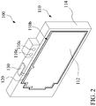
FIG. 2 is a three-dimensional view of the liquid cooling device according to the first embodiment of this disclosure. -
FIG. 3 is a circuit diagram of the liquid cooling device according to the first embodiment of this disclosure. -
FIG. 4 is an enlarged three-dimensional view of partial components of the liquid cooling device according to the first embodiment of this disclosure. -
FIG. 5 is an exploded three-dimensional view of the liquid cooling device according to a second embodiment of this disclosure. -
FIG. 6 is a three-dimensional view of the liquid cooling device according to a third embodiment of this disclosure. -
FIG. 7 is a three-dimensional view of a coolant circulation system according to a fourth embodiment of this disclosure. -
FIG. 8 andFIG. 9 are exploded three-dimensional views of the liquid cooling device according to a fifth embodiment of this disclosure. -
FIG. 10 is a three-dimensional view of the liquid cooling device according to the fifth embodiment of this disclosure. -
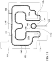
FIG. 11 is a top view of a first insulator according to the fifth embodiment of this disclosure. -
FIG. 12 is another top view of the first insulator according to the fifth embodiment of this disclosure. -
FIG. 13 is a top view of the first insulator according to a sixth embodiment of this disclosure. -
FIG. 14 is a top view of the first insulator according to seventh embodiment of this disclosure. -
FIG. 15 is a top view of the first insulator according to an eighth embodiment of this disclosure. -
FIG. 16 is a partial top view of the first insulator according to the eighth embodiment of this disclosure. -
FIG. 17 is a partial top view of the first insulator according to a ninth embodiment of this disclosure. -
FIG. 18 is a partial top view of the first insulator according to a tenth embodiment of this disclosure. -
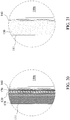
FIG. 19 andFIG. 20 are partial top views of the first insulator according to a eleventh embodiment of this disclosure. -
FIG. 21 is a partial top view of the first insulator according to a twelfth embodiment of this disclosure. -
FIG. 22 is a flow chart of a liquid leakage detecting method according to this disclosure. - Referring to
FIG. 1 andFIG. 2 , which show aliquid cooling device 100 according to a first embodiment of this disclosure. Theliquid cooling device 100 is configured to contact a heat source and provide a coolant to circulate inside theliquid cooling device 100, so as to cool the heat source quickly. The heat source may be, but not limited to, a high-power electronic chip such as a central processing unit (CPU) or a graphics processing unit (GPU). - As shown in
FIG. 1 andFIG. 2 , theliquid cooling device 100 includes at least oneliquid cooling conductor 110, a detectingprobe 120, and a determiningcircuit 130. - As shown in
FIG. 1 , theliquid cooling conductor 110 includes achamber 110a defined therein for communicating with the outside, so as to allow an external coolant to flow therein and accommodate the coolant. Based on the limitations of machining techniques, theliquid cooling conductor 110 is generally formed by joining two or more combination blocks to form thechamber 110a. Meanwhile, in order to serve as a good heat transfer medium, at least one of the combination blocks is ametal conductor 112 for contacting the heat source to rapidly transfer the heat generated by the heat source to the coolant in thechamber 110a. Taking the first embodiment as an example, one combination block is ametal conductor 112, and the other combination block is aninsulator 114, such as a container-like structural member made of acrylic. - Certainly, it is not excluded that all of the combination blocks are
metal conductors 112. Aseam 110b is formed between two combination blocks in theliquid cooling conductor 110 formed by joining the at least two combination blocks. Theseam 110b may cause leakage to damage surrounding circuits. In addition, the coolant flowing in thechamber 110a is continuously circulated and exchanged with an external cooler or cooling water tank. Therefore, the surface of theliquid cooling conductor 110 is further provided with one or more communicatingports 110c communicating with thechamber 110a such that thechamber 110a is connected to acirculation device 200 by a pipe 230 (seeFIG. 7 ). In the first embodiment, the surface of theliquid cooling conductor 110 is provided with two communicatingports 110c communicating with thechamber 110a, one of the communicatingports 110c is configured for the coolant to flow from areservoir 210 such as a cooler or a cooling water tank to thechamber 110a, and the other communicatingport 110c is configured for the coolant absorbing the heat to leave thechamber 110a and return to thereservoir 210 for cooling. Aseam 110b that may leak liquid is also formed around the communicatingport 110c. - As shown in
FIG. 1 andFIG. 2 , the detectingprobe 120 is disposed on theliquid cooling conductor 110, and is normally electrically disconnected from themetal conductor 112. In the first embodiment, the other combination block is aninsulator 114. Thus, the detectingprobe 120 can be directly disposed on theinsulator 114 without contact themetal conductor 112, so that the detectingprobe 120 can be normally electrically disconnected from themetal conductor 112. - As shown in
FIG. 1 andFIG. 2 , theinsulator 114 of theliquid cooling conductor 110 has a trough machined by turn-milling, such that theinsulator 114 is a container-like member. Themetal conductor 112 is a plate, and can seal the trough to form thechamber 110a. As shown inFIG. 2 , themetal conductor 112 partially covers the surface of theinsulator 114. In this case, the detectingprobe 120 is ideally disposed on the surface of theinsulator 114, and surrounds themetal conductor 112 but does not contact themetal conductor 112, for example, the detectingprobe 120 is disposed in parallel beside theseam 110b. - In this case, the
seam 110b is located at the edge of themetal conductor 112, regardless of the arrangement direction of the liquid cooling conductor 110 (the arrangement direction of theliquid cooling conductor 110 meets the requirement of contact between themetal conductor 112 and the heat source), and the leaking coolant can flow outward and contact the detectingprobe 120, so that the detectingprobe 120 is electrically connected to themetal conductor 112 through the coolant. - As shown in
FIG. 2 andFIG. 3 , the determiningcircuit 130 is electrically connected to themetal conductor 112 and the detectingprobe 120 for generating a liquid leakage alarm signal when themetal conductor 112 and the detectingprobe 120 are electrically connected. In an example, the determiningcircuit 130 applies a potential difference to the detectingprobe 120 and themetal conductor 112, for example, a first detecting potential VI is applied to the detectingprobe 120, themetal conductor 112 is electrically grounded as a second detecting potential V2, and a potential difference of subtracting V2 from VI is thus formed. The determiningcircuit 130 determines whether current is generated between the detectingprobe 120 and themetal conductor 112. The coolant normally contacts themetal conductor 112 in thechamber 110a. If the leaking coolant contacts the detectingprobe 120, the detectingprobe 120 and themetal conductor 112 are electrically connected through the leaking coolant to generate current, thereby triggering the determiningcircuit 130 to generate a liquid leakage alarm signal. The circuit shown inFIG. 3 is one of the implementations of current detection, but the detecting means for determining whether theelectrode 120 and themetal conductor 112 are electrically connected is not limited to the disclosure ofFIG. 3 . - Referring to
FIG. 4 , aseam 110b that may leak liquid is also formed around the communicatingport 110c. Therefore, in the first embodiment, another detectingprobe 120 is disposed on the combination block to surround at least one communicatingport 110c. If theseam 110b around the communicatingport 110c leaks coolant, the detectingprobe 120 and themetal conductor 112 are also conducted to trigger the determiningcircuit 130 to generate a liquid leakage alarm signal. - As shown in
FIG. 5 , the combination blocks of theliquid cooling conductor 110 according to a second embodiment are allmetal conductors 112. Thus, theliquid cooling device 100 further includes an insulatingpatch 140 attached to one of themetal conductors 112, and the detectingprobe 120 is attached to the insulatingpatch 140, so that the detectingprobe 120 is disposed on theliquid cooling conductor 110 and normally electrically disconnected from themetal conductor 112 through the insulatingpatch 140. - Referring to
FIG. 6 , which shows aliquid cooling device 100 according to a third embodiment of this disclosure. Theliquid cooling device 100 according to the third embodiment also includes at least oneliquid cooling conductor 110, a detectingprobe 120 and a determiningcircuit 130. - As shown in
FIG. 6 , the detectingprobe 120 does not need to continuously extend to surround theliquid cooling conductor 110. The leaking coolant usually flows downward with gravity. The detectingprobe 120 is ideally located below theseam 110b, and is as close as possible to theseam 110b without surrounding to immediately contact the coolant as liquid leaks. That is, at least partial detectingprobe 120 is located below theseam 110b in the direction of gravity. Thus, when the detectingprobe 120 is disposed, it is necessary to consider the state in which theliquid cooling conductor 110 is actually mounted on the heat source, and to confirm the position of theseam 110b, so as to determine the position of the detectingprobe 120. - In addition, the electrical conductivity of tap water is generally about 350 µS/cm, the electrical conductivity of reverse osmosis pure water is only 10 µS/cm. The electrical conductivity of the coolant regulated with additives and water may increase or decrease. Weak current or voltage conducted by the coolant under low electrical conductivity can be detected after moderate signal amplification. The distance between the detecting
probe 120 and theseam 110b also needs to be shortened to shorten the conductive path between the detectingprobe 120 and themetal conductor 112 to increase the current when conducting, so as to simplify the requirement of the determiningcircuit 130 for sensitivity to the detection of a conductive state. - Referring to
FIG. 7 , based on the foregoing embodiments, a fourth embodiment of this disclosure provides a coolant circulation system, including theliquid cooling device 100 as proposed in the foregoing embodiments and acirculation device 200. Theliquid cooling device 100 includes aliquid cooling conductor 110, a detectingprobe 120 and a determiningcircuit 130, the structure and the connection relationship of which are as described in the foregoing embodiments, and omitted here. - As shown in
FIG. 7 , thecirculation device 200 includes areservoir 210, aliquid pump 220, apipe 230, and adriving circuit 240. - The
liquid pump 220 is connected to the communicatingport 110c and thereservoir 210 by thepipe 230 to pump the coolant to circulate between thechamber 110a of theliquid cooling conductor 110 and thereservoir 210. - The driving
circuit 240 is electrically connected to theliquid pump 220 and the determiningcircuit 130 of the liquid coolingheat conducting device 100. The drivingcircuit 240 is configured to provide driving power to drive theliquid pump 220 to pump the coolant, and the drivingcircuit 240 shuts down theliquid pump 220 when receiving the liquid leakage alarm signal to stop pumping the coolant so as to avoid continuous liquid leakage. - The foregoing
driving circuit 240 may be an independent circuit, directly gets power by a power supply of a computer host, and directly receives the liquid leakage alarm signal of the determiningcircuit 130 by a pin. The drivingcircuit 240 and the determiningcircuit 130 may also be bridged by an embedded board controller (EBC) of a computer motherboard; in this case, the liquid leakage alarm signal can be further transmitted to the motherboard in addition to thedriving circuit 240, to generate alarm information by using a built-in function of an operating system or a loaded monitoring program to inform the user. Certainly, the drivingcircuit 240 and the determiningcircuit 130 may also be partially or completely integrated into the embedded controller as a part of the motherboard. - In addition, as shown in
FIG. 7 , theliquid cooling device 100 may further include analarm 150, such as an indicator light device or an alarm sound device, electrically connected to the determiningcircuit 130. When liquid leaks and the determiningcircuit 130 sends a liquid leakage alarm signal, thealarm 150 can receive the liquid leakage alarm signal to generate corresponding alarm message, for example, the indicator light device emits indication light or the alarm sound device emits an alarm sound. - Referring to
FIG. 8 ,FIG. 9 andFIG. 10 , which show aliquid cooling device 100 according to a fifth embodiment of this disclosure. Theliquid cooling device 100 includes at least oneliquid cooling conductor 110, a detectingprobe 120, and a sealingmember 160. - In the fifth embodiment, the
liquid cooling conductor 110 is formed by joining three combination blocks. The three combination blocks include at least onemetal conductor 112, afirst insulator 111 and asecond insulator 113. Thefirst insulator 111 is substantially a plate having one or more throughholes 111a and afirst trough 111b. Thefirst trough 111b is located on a first side of thefirst insulator 111, and the throughhole 111a communicates with the first side and a second side of thefirst insulator 111. Thesecond insulator 113 is joined to the first side of thefirst insulator 111 to cover thefirst trough 111b, and the throughhole 111a communicates with thefirst trough 111b and the second side of thefirst insulator 111. Themetal conductor 112 is joined to the second side of thefirst insulator 111 to cover the throughhole 111a, so that thefirst trough 111b and the throughhole 111a are sealed into achamber 110a, and the coolant circulated in thechamber 110a can contact themetal conductor 112. The side of thesecond insulator 113 facing thefirst trough 111b may also be provided with asecond trough 113a that is in the same projection shape as or is slightly larger than thefirst trough 111b, to increase the volume of thechamber 110a. In the fifth embodiment, thefirst trough 111b and thesecond trough 113a are U-shaped, and the two throughholes 111a are respectively disposed corresponding to two ends of the U-shaped openings, so that the coolant flowing through the two throughholes 111a can be sufficiently circulated to different portions of theU-shaped chamber 110a. Therefore, thechamber 110a includes the throughhole 111a, thefirst trough 111b and thesecond trough 113a that communicate with each other. Or, it may also provide only thefirst trough 111b or thesecond trough 113a to form thechamber 110a separately. - As shown in
FIG. 8 andFIG. 9 , themetal conductor 112 is generally a metal plate, and is smaller than the second side of thefirst insulator 111 in area. Themetal conductor 112 further includes athird trough 112a. Themetal conductor 112 is joined to the second side of thefirst insulator 111, and thethird trough 112a faces the throughholes 111a. Thethird trough 112a can be used to increase the volume of thechamber 110a. - The
second insulator 113 may be disposed at the communicatingport 110c communicating with thechamber 110a. The communicatingport 110c is configured for connecting thechamber 110a to thecirculation device 200 by a pipe 230 (seeFIG. 7 ). The communicatingport 110c may extend from the outer surface of thesecond insulator 113 to thesecond trough 113a, and communicate with thechamber 110a through thesecond trough 113a. The communicatingport 110c may also penetrate the solid portion of thesecond insulator 113 through the outer surface of thesecond insulator 113, and further penetrate the solid portion of thefirst insulator 111 to communicate with thethird trough 112a of themetal conductor 112 and then communicate with thechamber 110a. The second side of thefirst insulator 111 may further be provided with afourth trough 111c corresponding to the communicatingport 110c to extend the volume of thechamber 110a. - As shown in
FIG. 8 andFIG. 11 , the detectingprobe 120 is disposed on theliquid cooling conductor 110, and is normally electrically disconnected from themetal conductor 112. In the fifth embodiment, thefirst insulator 111 and thesecond insulator 113 are electrically insulated, and form aseam 110b along the boundary of thechamber 110a. Therefore, the detectingprobe 120 may be disposed on thefirst insulator 111 or thesecond insulator 113 so as not to be in contact with themetal conductor 112, and the detectingprobe 120 is normally electrically disconnected from themetal conductor 112. - As shown in
FIG. 8 andFIG. 11 , the detectingprobe 120 is disposed on thefirst insulator 111 or thesecond insulator 113, surrounds the boundary of thesecond trough 113a, and is located outside theseam 110b. Substantially, each section of the detectingprobe 120 is disposed in parallel beside theseam 110b.FIG. 11 shows an example in which the detectingprobe 120 is disposed on the first insulator 111 (on the side of thefirst insulator 111 having thefirst trough 111b). The detectingprobe 120 may be fabricated by printing a conductive paint and extends to form awire segment 122. Thewire segment 122 extends to a position that is not covered by thefirst insulator 111, e.g., the outer surface of thefirst insulator 111, to be exposed and thus can be connected to a supply source of the first detecting potential V1. - As shown in
FIG. 8 andFIG. 11 , the sealingmember 160 may be a rubber ring or a soft annular patch, the shape of which is substantially the same as the projection shape of the detectingprobe 120 or theseam 110b, but the size is slightly larger than the projection of theseam 110b and slightly smaller than the detectingprobe 120. The sealingmember 160 surrounds theseam 110b and is located inside the detectingprobe 120, i.e., between the detectingprobe 120 and theseam 110b. In general, when the sealingmember 160 is a rubber ring, thefirst insulator 111 or thesecond insulator 113 may be provided with a groove corresponding to the rubber ring, so that the rubber ring is temporarily fixed to thefirst insulator 111 or thesecond insulator 113. - The sealing
member 160 is configured to seal the joint interface of thefirst insulator 111 or thesecond insulator 113 to further seal theseam 110b, so as to prevent theseam 110b from leaking the coolant. After the sealingmember 160 is aged and coolant leaks through the sealingmember 160, the leaking coolant contacts the detectingprobe 120 at first, so that the detectingprobe 120 is electrically connected to themetal conductor 112 via the coolant. In this case, with the circuit ofFIG. 3 or other detecting means for determining whether the detectingprobe 120 and themetal conductor 112 are electrically connected, the liquid leakage alarm is immediately generated, and the operation of thecirculation device 200 is stopped, thereby avoiding the damage of liquid leakage to the computer system. - As shown in
FIG. 8 andFIG. 11 , aseam 110b that may leak liquid is also formed around the communicatingport 110c. Therefore, the detectingprobe 120 may also surround the communicatingport 110c. Similarly, a sealingmember 160 surrounding theseam 110b is also disposed between theseam 110b around the communicatingport 110c and the detectingprobe 120. When the communicatingport 110c penetrates the joint interface of thefirst insulator 111 or thesecond insulator 113, the communicatingport 110c actually become a part of thechamber 110a, and the edge of the communicatingport 110c passes through the joint interface to form theseam 110b. - The sealing
member 160 is located inside the detectingprobe 120 to seal theseam 110b around the communicatingport 110c, so as to avoid leakage of the coolant around the communicatingport 110c. If liquid leakage occurs, the detectingprobe 120 and themetal conductor 112 are also electrically connected to trigger the determiningcircuit 130 to generate a liquid leakage alarm. As described above, if thefirst insulator 111 or thesecond insulator 113 is replaced with themetal conductor 112, themetal conductor 112 and the detectingprobe 120 can be isolated by an insulatingpatch 140, so that the detectingprobe 120 can be normally electrically disconnected from themetal conductor 112 by the insulatingpatch 140. - Referring to
FIG. 12 , which is another top view of thefirst insulator 111 according to the fifth embodiment of this disclosure.FIG. 12 of the fifth embodiment is substantially the same as the fourth embodiment except that the detectingprobe 120 does not continuously extend around theliquid cooling conductor 110 by a circle. Considering a state in which theliquid cooling conductor 110 is actually mounted on the heat source, after the position of theseam 110b is confirmed, the detectingprobe 120 is partially disposed under theseam 110b and is as close as possible to theseam 110b. That is, the detectingprobe 120 is partially located below theseam 110b in the direction of gravity. When liquid leakage occurs, the leaking coolant flows downward under the action of gravity to contact the detectingprobe 120 below theseam 110b. In this embodiment, the sealingmember 160 still surrounds theseam 110b and passes between the detectingprobe 120 and theseam 110b. - Referring to
FIG. 13 , which is a top view of thefirst insulator 111 according to a sixth embodiment of this disclosure. Theliquid cooling device 100 includes at least oneliquid cooling conductor 110, a detectingprobe 120, and a plurality of sealingmembers 160. The sixth embodiment is substantially the same as the fifth embodiment, and the differences are described below. - In the plurality of sealing members 160 (illustrated as two in
FIG. 13 ), at least one sealingmember 160 surrounds theseam 110b and is located between theseam 110b and the detectingprobe 120, and at least another sealingmember 160 surrounds theseam 110b and is located outside the detectingprobe 120. Therefore, after the sealingmember 160 on the inner ring is aged, the detectingprobe 120 can detect the liquid leakage state immediately, and meanwhile, the sealingmember 160 on the outer ring can be used as a backup means to prevent the leaking coolant from continuing to flow out. The detectingprobe 120 according to the sixth embodiment of this disclosure can also be modified to discontinuously extend and not surround theliquid cooling conductor 110. That is, the detectingprobe 120 is partially disposed under theseam 110b and located between two sealingmembers 160. - Referring to
FIG. 14 , which is a top view of thefirst insulator 111 according to a seventh embodiment of this disclosure. Theliquid cooling device 100 includes at least oneliquid cooling conductor 110, a detectingprobe 120, and a plurality of sealingmembers - In the plurality of sealing
members FIG. 14 ), at least one sealingmember 160a is a conductive rubber ring, and is electrically connected to the detectingprobe 120 or connected to the same detecting circuit together with the detectingprobe 120. The conductive rubber ring as the sealingmember 160a may be located outside the detectingprobe 120. After the sealingmember 160 on the inner ring is aged, the detectingprobe 120 can detect the liquid leakage state immediately, and meanwhile, the sealingmember 160a on the outer ring can be used as a backup sealing means to prevent the leaking coolant from continuing to flow out. In addition, the sealingmember 160a on the outer ring is also a backup detecting means to avoid the failure of the detectingprobe 120 due to various factors (e.g., poor conductivity caused by surface oxidation). The detectingprobe 120 according to the seventh embodiment can also be modified to discontinuously extend and not surround theliquid cooling conductor 110. That is, the detectingprobe 120 is partially disposed under theseam 110b and located between two sealingmembers - Referring to
FIG. 15 andFIG. 16 , which is aliquid cooling device 100 according to an eighth embodiment of this disclosure. The liquid cooling device100 includes at least oneliquid cooling conductor 110, a detectingprobe 120, a sealingmember 160, and acapillary structure 170. The eighth embodiment is substantially the same as fifth embodiment, and the differences are described below. - As shown in
FIG. 15 andFIG. 16 , in the eighth embodiment the detectingprobe 120 is spaced from the sealingmember 160. Thecapillary structure 170 is disposed between the detectingprobe 120 and the sealing member 16. In the eight embodiments, the detecting probe120 is disposed around the sealingmember 160 and the seam110b, and thecapillary structure 170 is also disposed around the sealingmember 160 and the seam110b. If the detectingprobe 120 is partially disposed as shown inFIG. 12 , thecapillary structure 170 can be also partially disposed, and the length of thecapillary structure 170 is approximately equaled to the length of the detectingprobe 120. - As shown in
FIG. 15 andFIG. 16 , thecapillary structure 170 can be made of absorbent material, such as foam, sponge, fiber sheet, porous material. When the sealingmember 160 is aged and the coolant leaks through the sealingmember 160, the coolant would be immediately absorbed by thecapillary structure 170. At least partial section of thecapillary structure 170 would be wetted completely by the coolant, so as to prevent the leaking coolant from forming a droplet due to cohesive force to cut off the connection with the coolant in thechamber 110a. The completely wettedcapillary structure 170 contacts the detecting probe120, such that detectingprobe 120 and themetal conductor 112 are electrically connected through the coolant. In this case, with the circuit ofFIG. 3 or other detecting means for determining whether the detectingprobe 120 and themetal conductor 112 are electrically connected, the liquid leakage alarm is immediately generated, and the operation of thecirculation device 200 is stopped, thereby avoiding the damage of liquid leakage to the computer system. - Referring to
FIG. 17 , which is a partial top view of thefirst insulator 111 according to a ninth embodiment of this disclosure. The ninth embodiment is substantially the same as the eighth embodiment, and the differences are described below. In the ninth embodiment, thecapillary structure 170 is a surface structure formed on surface of the insulator (thefirst insulator 111 or thesecond insulator 113. The surface structure included a plurality of micro grooves extending from the sealingmember 160 to the detectingprobe 120. The surface structure would be wetted completely by the coolant, so as to prevent the leaking coolant from forming a droplet due to cohesive force to cut off the connection with the coolant in thechamber 110a. Regardless the sealingmember 160 is directly attached on the insulator (the surface of thefirst insulator 111 or the second insulator 113) or embedded into the groove on the surface of the insulator, the sealingmember 160 will protrude on the surface of the insulator, and must has a height higher than the height of the surface structure. When the sealingmember 160 is compressed to seal thechamber 110a, the height of the sealingmember 160 is still higher than that of the surface structure, so as to prevent from being unable to be compressed due to a high surface structure. - Referring to
FIG. 18 , which is a partial top view of afirst insulator 111 according to a tenth embodiment of this disclosure. The tenth embodiment is substantially the same as the ninth embodiment, and the differences are described below. In tenth embodiment, thecapillary structure 170 includes anabsorbent material 170a and asurface structure 170b formed on a surface of the insulator, for example, a plurality micro grooves disposed beside the sealingmember 160 and a sponge disposed beside the detecting probe120, so as to lead the leaking coolant to contact the detectingprobe 120. - Referring to
FIG. 19 and20 , which is a partial top view of thefirst insulator 111 according to an eleventh embodiment of this disclosure. The eleventh embodiment is substantially the same as the eighth embodiment, and the differences are described below. In the eleventh embodiment, thecapillary structure 170 is a surface structure formed on the surface of the (thefirst insulator 111 or the second insulator 113), and covers the surface of the insulator excepting the part disposing the sealingmember 160. - As shown in
FIG. 19 , the surface structure is hairline texture formed by hairline surfaced treatment. And the hairline texture at least includes two sets of directional interleaving hairlines, so as to make leaking coolant diffusing on the surface structure well. - As shown in
FIG. 20 , the detectingprobe 120 may be directly attached on the surface structure, and contact or be spaced from the sealingmember 160. In the eleventh embodiment, the surface structure occupies most of the surface of the insulator (theinsulator 111 or the second insulator 113) instead of being disposed within the narrow gap of the sealingmember 160 and the detectingprobe 120. The surface structure occupying large area of the surface can reduce treatment difficulty and tolerance in assembly. Meanwhile surface structure occupying large area of the surface can absorb more leaking coolant to prevent the leaking coolant from dropping down. - Referring to
FIG. 21 , which is a partial top view of thefirst insulator 111 according to a twelfth embodiment of this disclosure. In the twelfth embodiment, the detectingprobe 120 is disposed on the surface of the insulator (thefirst insulator 111 or the second insulator 113), and covers the surface of the insulator excepting the part disposing the sealingmember 160. Meanwhile, the detectingprobe 120 is configured in to capillary structure. For example, graphite is printed on the surface of the insulator by screen printing, to form the detectingprobe 120. Therefore, the detectingprobe 120 itself is the capillary structure to absorb the leaking coolant well, so as to prevent the leaking coolant from forming a droplet due to cohesive force to cut off the connection with the coolant in thechamber 110a. Providing that the detectingprobe 120 is a capillary structure occupying large area of the surface, the manufacturing process of the detectingprobe 120 can be simplified, and the detectingprobe 120 can absorb the leaking coolant well. - Referring to
FIG. 22 , based on the above combination, this disclosure further provides a liquid leakage detecting method for aliquid cooling conductor 110, including the following steps. - As shown in
Step 110, first, a detectingprobe 120 is provided, and the detectingprobe 120 is disposed beside aseam 110b or disposed around at least one communicatingport 110c, wherein theseam 110b is formed on aliquid cooling conductor 110 by joining at least two combination blocks, and the communicatingport 110c communicates with the interior of theliquid cooling conductor 110. Theliquid cooling conductor 110 is not limited to being formed by joining two combination blocks, and may be formed by joining three combination blocks as in Embodiments 5 to 7. - The detecting
probe 120 needs to be normally electrically insulated from ametal conductor 112 of theliquid cooling conductor 110. If theliquid cooling conductor 110 includes aninsulator 114 portion, the detectingprobe 120 is disposed on theinsulator 114. If theliquid cooling conductor 110 is entirely composed of themetal conductor 112, or the detectingprobe 120 needs to be disposed on themetal conductor 112 such that the detectingprobe 120 is located below theseam 110b in the direction of gravity, an insulatingpatch 140 is first attached to themetal conductor 112, and then the detectingprobe 120 is attached to the insulatingpatch 140. Further, as in Embodiment 5, a sealingmember 160 may be provided, which surrounds theseam 110b or the communicatingport 110c, and is located inside the detectingprobe 120. Alternatively, as in Embodiment 6 and Embodiment 7, another sealingmember seam 110b or the communicatingport 110c, and is located outside the detectingprobe 120. The another sealingmember probe 120. - As shown in
Step 120, a first detecting potential VI is provided for the detectingprobe 120, and a second detecting potential V2 is provided for themetal conductor 112. Generally, the second detecting potential V2 may be a ground potential. That is, themetal conductor 112 is grounded. When the conductive rubber ring is disposed outside the detectingprobe 120, the first detecting potential VI is also provided for the conductive rubber ring. The first detecting potential VI is provided for the conductive rubber ring by means of directly communicating the detectingprobe 120 with a line; for example, the detectingprobe 120 is fabricated by printing a conductive paint and extends to form awire segment 122, and the conductive rubber ring contacts thewire segment 122. Alternatively, aseparate wire segment 122 is fabricated by printing a conductive paint, the conductive rubber ring contacts thewire segment 122, and thewire segment 122 is connected to a supply source of the first detecting potential V1. - As shown in
Step 130, whether the detectingprobe 120 and themetal conductor 112 are conducted is judged by measuring the current between the detectingprobe 120 and themetal conductor 112 or by other detecting means. - As shown in
Step 140, when the detectingprobe 120 and themetal conductor 112 are conducted, a liquid leakage alarm signal is generated to drive analarm 150 to shut down aliquid pump 220, or is sent to the motherboard to warn the user through an operating system. - According to this disclosure, the detecting
probe 120 and themetal conductor 112 of theliquid cooling conductor 110 are used as liquid leakage probes, and a relatively simple trigger circuit can be used as the determiningcircuit 130, so that the liquid leakage alarm function can be integrated into a part of the existingliquid cooling device 100, without a complicated detecting system or changing of the structure of theliquid cooling conductor 110. In addition, the liquid leakage alarm signal can be used for shutting down theliquid pump 220 in real time to avoid the continuous occurrence of leakage from destroying surrounding electronic components, and real-time intervention of a user is not required, so that this disclosure has a liquid leakage protection function.
Claims (15)
- A liquid cooling device (100), comprising:a liquid cooling conductor (110), including a chamber (110a) defined therein for communicating with outside, the chamber (110a) being configured to accommodate a coolant, and the surface of the liquid cooling conductor (110) being provided with at least one communicating port (110c) communicating with the chamber (110a); wherein the liquid cooling conductor (110) is formed by joining at least two combination blocks, and at least one of the at least two combination blocks is a metal conductor (112);a detecting probe (120), disposed on the liquid cooling conductor (110) and normally electrically disconnected from the metal conductor (112); anda determining circuit (130), electrically connected to the metal conductor (112) and the detecting probe (114), and generating a liquid leakage alarm signal when the metal conductor (112) and the detecting probe (120) are electrically connected.
- The liquid cooling device (100) as claimed in Claim 1, wherein a seam (110b) is formed between the at least two combination blocks, and the detecting probe (120) is disposed beside the seam (110b); or the detecting probe (120) surrounds the at least one communicating port (110c).
- The liquid cooling device (100) as claimed in Claim 1, wherein one of the at least two combination blocks (112, 114) is a metal conductor (112), the other combination block is an insulator (114), and the detecting probe (120) is disposed on the insulator (114) without contacting the metal conductor (112); or the at least two combination blocks are metal conductors (112), and the liquid cooling device (100) further comprises an insulating patch (140) attached to the metal conductor (112), and the detecting probe (120) is attached to the insulating patch (140).
- The liquid cooling device (100) as claimed in Claim 2, further comprising a sealing member (160) surrounding the seam (110b) or the communicating port (110c) and located inside the detecting probe (120).
- The liquid cooling device (100) as claimed in Claim 4, further comprising another sealing member (160) surrounding the seam (110b) or the communicating port (110c) and located outside the detecting probe (120).
- The liquid cooling device (100) as claimed in Claim 5, wherein the another sealing member (160) is a conductive rubber ring and is electrically connected to the detecting probe (120).
- The liquid cooling device (100) as claimed in Claim 4, further comprising a capillary structure (170), disposed between the detecting probe (120) and the sealing member (160).
- The liquid cooling device (100) as claimed in Claim 7, wherein the capillary structure (170) is made of absorbent material.
- The liquid cooling device (100) as claimed in Claim 7, wherein the capillary structure (170) is surface structure formed on a surface of the insulator (114).
- The liquid cooling device (100) as claimed in Claim 9, wherein the surface structure covers the surface of the insulator excepting the part disposing the sealing member.
- The liquid cooling device (100) as claimed in Claim 10, wherein the detecting probe (120) is attached on the surface structure (170).
- The liquid cooling device (100) as claimed in Claim 4, wherein the detecting probe (120) is configured into a capillary structure (170), and the detecting probe (120) covers the surface of the insulator (114) excepting the part disposing the sealing member (160).
- A coolant circulation system, comprising:the liquid cooling device (100) according to any of Claims 1-12;a liquid pump (220), connected to the at least one communicating port (110c) by a pipe (230); anda driving circuit (240), electrically connected to the liquid pump (220) and the determining circuit (130) for driving the liquid pump (220), and shutting down the liquid pump (220) when receiving the liquid leakage alarm signal from the determining circuit (130).
- A liquid leakage detecting method, comprising:disposing a detecting probe (120) beside a seam (110b), or disposing the detecting probe (120) around at least one communicating port (110c), wherein the seam (110b) is formed on a liquid cooling conductor (110) by joining at least two combination blocks, and the at least one communicating port (110c) communicates with the interior of the liquid cooling conductor (110);providing a first detecting potential for the detecting probe (120), and providing a second detecting potential for a metal conductor (112) on the liquid cooling conductor (110); anddetermining whether the detecting probe (120) and the metal conductor (112) are electrically connected, and generating a liquid leakage alarm signal when the detecting probe (120) and the metal conductor (112) are electrically connected.
- The liquid leakage detecting method as claimed in Claim 14, wherein the step of disposing a detecting probe (120) beside a seam (110b) comprises:
disposing the detecting probe (120) at an insulator portion of the liquid cooling conductor (110).
Applications Claiming Priority (2)
| Application Number | Priority Date | Filing Date | Title |
|---|---|---|---|
| TW107118826 | 2018-05-31 | ||
| TW107144005 | 2018-12-06 |
Publications (2)
| Publication Number | Publication Date |
|---|---|
| EP3575921A1 true EP3575921A1 (en) | 2019-12-04 |
| EP3575921B1 EP3575921B1 (en) | 2022-05-04 |
Family
ID=66685371
Family Applications (1)
| Application Number | Title | Priority Date | Filing Date |
|---|---|---|---|
| EP19177273.0A Active EP3575921B1 (en) | 2018-05-31 | 2019-05-29 | Liquid cooling device, coolant circulation system and liquid leakage detecting method |
Country Status (3)
| Country | Link |
|---|---|
| US (1) | US11408692B2 (en) |
| EP (1) | EP3575921B1 (en) |
| TW (1) | TWI725422B (en) |
Cited By (2)
| Publication number | Priority date | Publication date | Assignee | Title |
|---|---|---|---|---|
| TWI806215B (en) * | 2021-11-03 | 2023-06-21 | 台達電子工業股份有限公司 | Leak detection sensor and leak detection system using same |
| CN119233598A (en) * | 2024-09-24 | 2024-12-31 | 苏州元脑智能科技有限公司 | Liquid cooling device and liquid cooling electronic equipment |
Families Citing this family (21)
| Publication number | Priority date | Publication date | Assignee | Title |
|---|---|---|---|---|
| US12366870B2 (en) | 2013-03-15 | 2025-07-22 | Coolit Systems, Inc. | Flow-path controllers and related systems |
| TWI531795B (en) | 2013-03-15 | 2016-05-01 | 水冷系統公司 | Sensors, multiplexed communication techniques, and related systems |
| US11452243B2 (en) | 2017-10-12 | 2022-09-20 | Coolit Systems, Inc. | Cooling system, controllers and methods |
| TWI725422B (en) * | 2018-05-31 | 2021-04-21 | 技嘉科技股份有限公司 | Liquid cooling device, coolant circulation system , and liquid leaking detection method |
| US11662037B2 (en) | 2019-01-18 | 2023-05-30 | Coolit Systems, Inc. | Fluid flow control valve for fluid flow systems, and methods |
| US11473860B2 (en) * | 2019-04-25 | 2022-10-18 | Coolit Systems, Inc. | Cooling module with leak detector and related systems |
| US11802807B2 (en) * | 2019-09-25 | 2023-10-31 | Dell Products L.P. | Leak detection apparatus for an information handling system |
| CN111366316A (en) * | 2020-02-19 | 2020-07-03 | 苏州浪潮智能科技有限公司 | System and method for detecting liquid in server and server |
| US12442712B2 (en) * | 2020-12-23 | 2025-10-14 | Intel Corporation | Liquid cooling system leak detection improvements |
| CN112924120A (en) * | 2021-01-26 | 2021-06-08 | 马鞍山十七冶工程科技有限责任公司 | Underground comprehensive pipe gallery seam leakage monitoring device and method |
| CN112860042B (en) * | 2021-02-09 | 2025-02-07 | 华勤技术股份有限公司 | Liquid cooling device and electronic equipment |
| US12216025B2 (en) | 2021-03-08 | 2025-02-04 | Baidu Usa Llc | Advanced sealing structure for liquid cooling |
| US20220291072A1 (en) * | 2021-03-10 | 2022-09-15 | Dell Products, Lp | Optical liquid coolant leak detector |
| US11991867B2 (en) * | 2021-05-21 | 2024-05-21 | Quanta Computer Inc. | Closed-loop liquid cooling system |
| CN114251616B (en) * | 2021-12-27 | 2023-11-24 | 北京印刷学院 | A focus self-tracking stage follow-up light device and its use method |
| US12200914B2 (en) | 2022-01-24 | 2025-01-14 | Coolit Systems, Inc. | Smart components, systems and methods for transferring heat |
| US20230301019A1 (en) * | 2022-03-18 | 2023-09-21 | Baidu Usa Llc | System on a chip based cooling system |
| TWI805363B (en) * | 2022-05-11 | 2023-06-11 | 英業達股份有限公司 | Liquid cooling plate for cpu |
| US12504344B2 (en) * | 2022-07-14 | 2025-12-23 | Dell Products L.P. | Liquid cooling leak sensor |
| TWI845004B (en) * | 2022-10-31 | 2024-06-11 | 技鋼科技股份有限公司 | Heat sink and electronic device |
| TWI886043B (en) * | 2024-09-12 | 2025-06-01 | 大陸商深圳興奇宏科技有限公司 | Water block structure |
Citations (3)
| Publication number | Priority date | Publication date | Assignee | Title |
|---|---|---|---|---|
| US20050092070A1 (en) * | 2003-10-09 | 2005-05-05 | Delphi Technologies, Inc. | Leak detection apparatus for a liquid circulation cooling system |
| US20140251583A1 (en) * | 2013-03-07 | 2014-09-11 | Asetek A/S | Leak detection system for a liquid cooling system |
| US20160178475A1 (en) * | 2014-12-17 | 2016-06-23 | Intel Corporation | Leak detection in liquid cooled computing systems |
Family Cites Families (36)
| Publication number | Priority date | Publication date | Assignee | Title |
|---|---|---|---|---|
| JPH0797617B2 (en) * | 1986-05-23 | 1995-10-18 | 株式会社日立製作所 | Refrigerant leakage prevention device |
| US4922232A (en) * | 1988-10-21 | 1990-05-01 | Bosich Joseph F | Leakage containment and detection systems |
| US5172730A (en) * | 1989-07-03 | 1992-12-22 | Insituform Of North American, Inc. | Two-wall leakage detection system for a pipe |
| JPH0827109B2 (en) * | 1990-07-12 | 1996-03-21 | 甲府日本電気株式会社 | Liquid cooling device |
| US5121929A (en) * | 1991-06-24 | 1992-06-16 | Fel-Pro Incorporated | Gasket with encased load sensor |
| US5865971A (en) * | 1996-03-22 | 1999-02-02 | Faraday Technology, Inc. | Sealing ring with electrochemical sensing electrode |
| US6026862A (en) * | 1997-02-14 | 2000-02-22 | Ameron International Corporation | Double containment pipe sections |
| US5918267A (en) * | 1997-06-04 | 1999-06-29 | Raychem Corporation | Leak detection |
| WO2002027256A2 (en) * | 2000-09-28 | 2002-04-04 | L & M Radiator, Inc. | Heat exchanger seal apparatus |
| US7009409B2 (en) * | 2001-08-10 | 2006-03-07 | Davie Neil R | Determination of gasket integrity by capacitance measurement |
| US6787718B2 (en) * | 2002-04-25 | 2004-09-07 | Agilent Technologies, Inc. | Device, method, and system for detecting the presence of liquid in proximity to electronic components |
| JP3641258B2 (en) * | 2002-08-26 | 2005-04-20 | 株式会社東芝 | Electronics |
| TW595757U (en) * | 2003-01-29 | 2004-06-21 | Jr-Ruei Li | Card-type liquid cooling heat sink module |
| SE527981C2 (en) * | 2004-06-04 | 2006-07-25 | Alfa Laval Corp Ab | Method and apparatus for assessing the risk of fluid leakage in a heat exchanger with sensor |
| US7096725B2 (en) * | 2004-11-08 | 2006-08-29 | Federal-Mogul World Wide, Inc. | Cylinder head gasket with integrated sensor |
| TWM273185U (en) * | 2005-02-04 | 2005-08-11 | Cooler Master Co Ltd | Alarm device for fluid circulation system |
| US7951182B2 (en) * | 2005-07-14 | 2011-05-31 | Zoll Circulation, Inc. | System and method for leak detection in external cooling pad |
| JP4358170B2 (en) * | 2005-08-30 | 2009-11-04 | 株式会社東芝 | Liquid leak detection structure |
| US8087430B1 (en) * | 2009-02-26 | 2012-01-03 | Betz James C | Leak detecting hose |
| WO2010118342A1 (en) * | 2009-04-09 | 2010-10-14 | Schlumberger Technology Corporation | Method and system for detection of fluid invasion in an annular space of flexible pipe |
| SE536618C2 (en) * | 2010-10-22 | 2014-04-01 | Alfa Laval Corp Ab | Heat exchanger plate and plate heat exchanger |
| SE535236C2 (en) * | 2010-10-22 | 2012-06-05 | Alfa Laval Corp Ab | Heat exchanger plate and plate heat exchanger |
| US8897013B2 (en) * | 2011-02-17 | 2014-11-25 | Lear Corporation | Sealed battery charger housing |
| US20120251859A1 (en) * | 2011-03-31 | 2012-10-04 | Lg Chem, Ltd. | Battery pack having liquid leak detection system |
| DK2653818T3 (en) * | 2012-04-20 | 2014-11-03 | Alfa Laval Corp Ab | HEAT EXCHANGER PLATE AND PLATE HEAT EXCHANGE |
| WO2013190611A1 (en) * | 2012-06-18 | 2013-12-27 | 日立ビークルエナジー株式会社 | Leak detecting apparatus |
| TWI531795B (en) * | 2013-03-15 | 2016-05-01 | 水冷系統公司 | Sensors, multiplexed communication techniques, and related systems |
| US9052252B2 (en) * | 2013-03-15 | 2015-06-09 | Coolit Systems, Inc. | Sensors, communication techniques, and related systems |
| JP2017010408A (en) * | 2015-06-24 | 2017-01-12 | 富士通株式会社 | Cooling device and electronic apparatus system |
| TWI602497B (en) * | 2015-09-16 | 2017-10-11 | 宏碁股份有限公司 | Thermal dissipation module |
| TWI616636B (en) * | 2016-07-28 | 2018-03-01 | 宏碁股份有限公司 | Heat sink |
| TWI613541B (en) * | 2016-08-11 | 2018-02-01 | 技嘉科技股份有限公司 | Liquid cooling system |
| TWM568025U (en) * | 2018-05-08 | 2018-10-01 | 大陸商上海綠曜能源科技有限公司 | Leak-detectable liquid-heat-transmission device |
| TWI725422B (en) * | 2018-05-31 | 2021-04-21 | 技嘉科技股份有限公司 | Liquid cooling device, coolant circulation system , and liquid leaking detection method |
| US20200025641A1 (en) * | 2018-07-18 | 2020-01-23 | Ling Long | Leak-detachable liquid-heat-transmission device |
| US11473860B2 (en) * | 2019-04-25 | 2022-10-18 | Coolit Systems, Inc. | Cooling module with leak detector and related systems |
-
2019
- 2019-05-06 TW TW108115628A patent/TWI725422B/en active
- 2019-05-29 EP EP19177273.0A patent/EP3575921B1/en active Active
- 2019-05-30 US US16/425,983 patent/US11408692B2/en active Active
Patent Citations (3)
| Publication number | Priority date | Publication date | Assignee | Title |
|---|---|---|---|---|
| US20050092070A1 (en) * | 2003-10-09 | 2005-05-05 | Delphi Technologies, Inc. | Leak detection apparatus for a liquid circulation cooling system |
| US20140251583A1 (en) * | 2013-03-07 | 2014-09-11 | Asetek A/S | Leak detection system for a liquid cooling system |
| US20160178475A1 (en) * | 2014-12-17 | 2016-06-23 | Intel Corporation | Leak detection in liquid cooled computing systems |
Cited By (2)
| Publication number | Priority date | Publication date | Assignee | Title |
|---|---|---|---|---|
| TWI806215B (en) * | 2021-11-03 | 2023-06-21 | 台達電子工業股份有限公司 | Leak detection sensor and leak detection system using same |
| CN119233598A (en) * | 2024-09-24 | 2024-12-31 | 苏州元脑智能科技有限公司 | Liquid cooling device and liquid cooling electronic equipment |
Also Published As
| Publication number | Publication date |
|---|---|
| TWI725422B (en) | 2021-04-21 |
| EP3575921B1 (en) | 2022-05-04 |
| US20190368832A1 (en) | 2019-12-05 |
| US11408692B2 (en) | 2022-08-09 |
| TW202005023A (en) | 2020-01-16 |
Similar Documents
| Publication | Publication Date | Title |
|---|---|---|
| US11408692B2 (en) | Liquid cooling device, coolant circulation system and liquid leakage detecting method | |
| CN110941314B (en) | Liquid-cooled heat conduction device, liquid-cooled circulation system, and liquid leakage detection method | |
| US7142425B2 (en) | Liquid cooling system including a liquid absorption and a leak detection device | |
| CN111397819B (en) | A system, method and readable storage medium for detecting liquid leakage of server coolant | |
| JP4512296B2 (en) | Liquid cooling system for portable information processing equipment | |
| CN105190274A (en) | Leak Detection System for Liquid Cooling Systems | |
| CN117130450B (en) | Liquid cooling plate components, servers and data centers | |
| US20160178475A1 (en) | Leak detection in liquid cooled computing systems | |
| CN213579962U (en) | Leak detection system | |
| CN112860042B (en) | Liquid cooling device and electronic equipment | |
| CN110568911B (en) | Server | |
| EP4007470B1 (en) | An advanced sealing structure for liquid cooling | |
| EP4007471A2 (en) | Leak detection and prevention system | |
| CN222939458U (en) | Power module and server | |
| CN214623562U (en) | Liquid cooling device and equipment | |
| JP2006066703A (en) | Cooling system, electrical equipment and warning device | |
| KR102185824B1 (en) | Heat dissipation structure of semiconductor package for power conversion | |
| CN115460833B (en) | Two-phase immersion liquid cooling equipment and system | |
| US10240997B2 (en) | Sensor members | |
| TW202111301A (en) | Server | |
| JPH02148891A (en) | Structure for cooling power source module of electronic equipment | |
| CN109195402A (en) | Heat abstractor and check out test set | |
| CN220674191U (en) | Cooling devices, electronic devices and power supply devices | |
| CN220087646U (en) | Vehicle-mounted domain controller device | |
| CN220986011U (en) | Power supply device, server node, and server |
Legal Events
| Date | Code | Title | Description |
|---|---|---|---|
| PUAI | Public reference made under article 153(3) epc to a published international application that has entered the european phase |
Free format text: ORIGINAL CODE: 0009012 |
|
| STAA | Information on the status of an ep patent application or granted ep patent |
Free format text: STATUS: THE APPLICATION HAS BEEN PUBLISHED |
|
| AK | Designated contracting states |
Kind code of ref document: A1 Designated state(s): AL AT BE BG CH CY CZ DE DK EE ES FI FR GB GR HR HU IE IS IT LI LT LU LV MC MK MT NL NO PL PT RO RS SE SI SK SM TR |
|
| AX | Request for extension of the european patent |
Extension state: BA ME |
|
| STAA | Information on the status of an ep patent application or granted ep patent |
Free format text: STATUS: REQUEST FOR EXAMINATION WAS MADE |
|
| 17P | Request for examination filed |
Effective date: 20200528 |
|
| RBV | Designated contracting states (corrected) |
Designated state(s): AL AT BE BG CH CY CZ DE DK EE ES FI FR GB GR HR HU IE IS IT LI LT LU LV MC MK MT NL NO PL PT RO RS SE SI SK SM TR |
|
| GRAP | Despatch of communication of intention to grant a patent |
Free format text: ORIGINAL CODE: EPIDOSNIGR1 |
|
| STAA | Information on the status of an ep patent application or granted ep patent |
Free format text: STATUS: GRANT OF PATENT IS INTENDED |
|
| RIC1 | Information provided on ipc code assigned before grant |
Ipc: H01L 23/473 20060101ALI20211110BHEP Ipc: H01L 23/373 20060101ALI20211110BHEP Ipc: G01M 3/18 20060101ALI20211110BHEP Ipc: G01M 3/16 20060101ALI20211110BHEP Ipc: H05K 7/20 20060101ALI20211110BHEP Ipc: G06F 1/20 20060101AFI20211110BHEP |
|
| INTG | Intention to grant announced |
Effective date: 20211206 |
|
| RAP3 | Party data changed (applicant data changed or rights of an application transferred) |
Owner name: GIGA-BYTE TECHNOLOGY CO., LTD. |
|
| RIN1 | Information on inventor provided before grant (corrected) |
Inventor name: WU, LIANG-YU Inventor name: LIN, YI-JHEN Inventor name: LU, CHING-YU Inventor name: MAO, TAI-CHUAN Inventor name: HUANG, SHUN-CHIH |
|
| GRAS | Grant fee paid |
Free format text: ORIGINAL CODE: EPIDOSNIGR3 |
|
| GRAA | (expected) grant |
Free format text: ORIGINAL CODE: 0009210 |
|
| STAA | Information on the status of an ep patent application or granted ep patent |
Free format text: STATUS: THE PATENT HAS BEEN GRANTED |
|
| AK | Designated contracting states |
Kind code of ref document: B1 Designated state(s): AL AT BE BG CH CY CZ DE DK EE ES FI FR GB GR HR HU IE IS IT LI LT LU LV MC MK MT NL NO PL PT RO RS SE SI SK SM TR |
|
| REG | Reference to a national code |
Ref country code: GB Ref legal event code: FG4D |
|
| REG | Reference to a national code |
Ref country code: CH Ref legal event code: EP |
|
| REG | Reference to a national code |
Ref country code: AT Ref legal event code: REF Ref document number: 1489762 Country of ref document: AT Kind code of ref document: T Effective date: 20220515 |
|
| REG | Reference to a national code |
Ref country code: IE Ref legal event code: FG4D Ref country code: DE Ref legal event code: R096 Ref document number: 602019014349 Country of ref document: DE |
|
| REG | Reference to a national code |
Ref country code: NL Ref legal event code: FP |
|
| REG | Reference to a national code |
Ref country code: LT Ref legal event code: MG9D |
|
| REG | Reference to a national code |
Ref country code: AT Ref legal event code: MK05 Ref document number: 1489762 Country of ref document: AT Kind code of ref document: T Effective date: 20220504 |
|
| PG25 | Lapsed in a contracting state [announced via postgrant information from national office to epo] |
Ref country code: SE Free format text: LAPSE BECAUSE OF FAILURE TO SUBMIT A TRANSLATION OF THE DESCRIPTION OR TO PAY THE FEE WITHIN THE PRESCRIBED TIME-LIMIT Effective date: 20220504 Ref country code: PT Free format text: LAPSE BECAUSE OF FAILURE TO SUBMIT A TRANSLATION OF THE DESCRIPTION OR TO PAY THE FEE WITHIN THE PRESCRIBED TIME-LIMIT Effective date: 20220905 Ref country code: NO Free format text: LAPSE BECAUSE OF FAILURE TO SUBMIT A TRANSLATION OF THE DESCRIPTION OR TO PAY THE FEE WITHIN THE PRESCRIBED TIME-LIMIT Effective date: 20220804 Ref country code: LT Free format text: LAPSE BECAUSE OF FAILURE TO SUBMIT A TRANSLATION OF THE DESCRIPTION OR TO PAY THE FEE WITHIN THE PRESCRIBED TIME-LIMIT Effective date: 20220504 Ref country code: HR Free format text: LAPSE BECAUSE OF FAILURE TO SUBMIT A TRANSLATION OF THE DESCRIPTION OR TO PAY THE FEE WITHIN THE PRESCRIBED TIME-LIMIT Effective date: 20220504 Ref country code: GR Free format text: LAPSE BECAUSE OF FAILURE TO SUBMIT A TRANSLATION OF THE DESCRIPTION OR TO PAY THE FEE WITHIN THE PRESCRIBED TIME-LIMIT Effective date: 20220805 Ref country code: FI Free format text: LAPSE BECAUSE OF FAILURE TO SUBMIT A TRANSLATION OF THE DESCRIPTION OR TO PAY THE FEE WITHIN THE PRESCRIBED TIME-LIMIT Effective date: 20220504 Ref country code: ES Free format text: LAPSE BECAUSE OF FAILURE TO SUBMIT A TRANSLATION OF THE DESCRIPTION OR TO PAY THE FEE WITHIN THE PRESCRIBED TIME-LIMIT Effective date: 20220504 Ref country code: BG Free format text: LAPSE BECAUSE OF FAILURE TO SUBMIT A TRANSLATION OF THE DESCRIPTION OR TO PAY THE FEE WITHIN THE PRESCRIBED TIME-LIMIT Effective date: 20220804 Ref country code: AT Free format text: LAPSE BECAUSE OF FAILURE TO SUBMIT A TRANSLATION OF THE DESCRIPTION OR TO PAY THE FEE WITHIN THE PRESCRIBED TIME-LIMIT Effective date: 20220504 |
|
| PG25 | Lapsed in a contracting state [announced via postgrant information from national office to epo] |
Ref country code: RS Free format text: LAPSE BECAUSE OF FAILURE TO SUBMIT A TRANSLATION OF THE DESCRIPTION OR TO PAY THE FEE WITHIN THE PRESCRIBED TIME-LIMIT Effective date: 20220504 Ref country code: PL Free format text: LAPSE BECAUSE OF FAILURE TO SUBMIT A TRANSLATION OF THE DESCRIPTION OR TO PAY THE FEE WITHIN THE PRESCRIBED TIME-LIMIT Effective date: 20220504 Ref country code: LV Free format text: LAPSE BECAUSE OF FAILURE TO SUBMIT A TRANSLATION OF THE DESCRIPTION OR TO PAY THE FEE WITHIN THE PRESCRIBED TIME-LIMIT Effective date: 20220504 Ref country code: IS Free format text: LAPSE BECAUSE OF FAILURE TO SUBMIT A TRANSLATION OF THE DESCRIPTION OR TO PAY THE FEE WITHIN THE PRESCRIBED TIME-LIMIT Effective date: 20220904 |
|
| REG | Reference to a national code |
Ref country code: CH Ref legal event code: PL |
|
| REG | Reference to a national code |
Ref country code: BE Ref legal event code: MM Effective date: 20220531 |
|
| PG25 | Lapsed in a contracting state [announced via postgrant information from national office to epo] |
Ref country code: SM Free format text: LAPSE BECAUSE OF FAILURE TO SUBMIT A TRANSLATION OF THE DESCRIPTION OR TO PAY THE FEE WITHIN THE PRESCRIBED TIME-LIMIT Effective date: 20220504 Ref country code: SK Free format text: LAPSE BECAUSE OF FAILURE TO SUBMIT A TRANSLATION OF THE DESCRIPTION OR TO PAY THE FEE WITHIN THE PRESCRIBED TIME-LIMIT Effective date: 20220504 Ref country code: RO Free format text: LAPSE BECAUSE OF FAILURE TO SUBMIT A TRANSLATION OF THE DESCRIPTION OR TO PAY THE FEE WITHIN THE PRESCRIBED TIME-LIMIT Effective date: 20220504 Ref country code: LU Free format text: LAPSE BECAUSE OF NON-PAYMENT OF DUE FEES Effective date: 20220529 Ref country code: LI Free format text: LAPSE BECAUSE OF NON-PAYMENT OF DUE FEES Effective date: 20220531 Ref country code: EE Free format text: LAPSE BECAUSE OF FAILURE TO SUBMIT A TRANSLATION OF THE DESCRIPTION OR TO PAY THE FEE WITHIN THE PRESCRIBED TIME-LIMIT Effective date: 20220504 Ref country code: DK Free format text: LAPSE BECAUSE OF FAILURE TO SUBMIT A TRANSLATION OF THE DESCRIPTION OR TO PAY THE FEE WITHIN THE PRESCRIBED TIME-LIMIT Effective date: 20220504 Ref country code: CZ Free format text: LAPSE BECAUSE OF FAILURE TO SUBMIT A TRANSLATION OF THE DESCRIPTION OR TO PAY THE FEE WITHIN THE PRESCRIBED TIME-LIMIT Effective date: 20220504 Ref country code: CH Free format text: LAPSE BECAUSE OF NON-PAYMENT OF DUE FEES Effective date: 20220531 |
|
| REG | Reference to a national code |
Ref country code: DE Ref legal event code: R097 Ref document number: 602019014349 Country of ref document: DE |
|
| PG25 | Lapsed in a contracting state [announced via postgrant information from national office to epo] |
Ref country code: MC Free format text: LAPSE BECAUSE OF FAILURE TO SUBMIT A TRANSLATION OF THE DESCRIPTION OR TO PAY THE FEE WITHIN THE PRESCRIBED TIME-LIMIT Effective date: 20220504 |
|
| PLBE | No opposition filed within time limit |
Free format text: ORIGINAL CODE: 0009261 |
|
| STAA | Information on the status of an ep patent application or granted ep patent |
Free format text: STATUS: NO OPPOSITION FILED WITHIN TIME LIMIT |
|
| PG25 | Lapsed in a contracting state [announced via postgrant information from national office to epo] |
Ref country code: AL Free format text: LAPSE BECAUSE OF FAILURE TO SUBMIT A TRANSLATION OF THE DESCRIPTION OR TO PAY THE FEE WITHIN THE PRESCRIBED TIME-LIMIT Effective date: 20220504 |
|
| 26N | No opposition filed |
Effective date: 20230207 |
|
| PG25 | Lapsed in a contracting state [announced via postgrant information from national office to epo] |
Ref country code: IE Free format text: LAPSE BECAUSE OF NON-PAYMENT OF DUE FEES Effective date: 20220529 |
|
| PG25 | Lapsed in a contracting state [announced via postgrant information from national office to epo] |
Ref country code: SI Free format text: LAPSE BECAUSE OF FAILURE TO SUBMIT A TRANSLATION OF THE DESCRIPTION OR TO PAY THE FEE WITHIN THE PRESCRIBED TIME-LIMIT Effective date: 20220504 Ref country code: BE Free format text: LAPSE BECAUSE OF NON-PAYMENT OF DUE FEES Effective date: 20220531 |
|
| PG25 | Lapsed in a contracting state [announced via postgrant information from national office to epo] |
Ref country code: IT Free format text: LAPSE BECAUSE OF FAILURE TO SUBMIT A TRANSLATION OF THE DESCRIPTION OR TO PAY THE FEE WITHIN THE PRESCRIBED TIME-LIMIT Effective date: 20220504 |
|
| PG25 | Lapsed in a contracting state [announced via postgrant information from national office to epo] |
Ref country code: HU Free format text: LAPSE BECAUSE OF FAILURE TO SUBMIT A TRANSLATION OF THE DESCRIPTION OR TO PAY THE FEE WITHIN THE PRESCRIBED TIME-LIMIT; INVALID AB INITIO Effective date: 20190529 |
|
| PG25 | Lapsed in a contracting state [announced via postgrant information from national office to epo] |
Ref country code: MK Free format text: LAPSE BECAUSE OF FAILURE TO SUBMIT A TRANSLATION OF THE DESCRIPTION OR TO PAY THE FEE WITHIN THE PRESCRIBED TIME-LIMIT Effective date: 20220504 Ref country code: CY Free format text: LAPSE BECAUSE OF FAILURE TO SUBMIT A TRANSLATION OF THE DESCRIPTION OR TO PAY THE FEE WITHIN THE PRESCRIBED TIME-LIMIT Effective date: 20220504 |
|
| PG25 | Lapsed in a contracting state [announced via postgrant information from national office to epo] |
Ref country code: MT Free format text: LAPSE BECAUSE OF FAILURE TO SUBMIT A TRANSLATION OF THE DESCRIPTION OR TO PAY THE FEE WITHIN THE PRESCRIBED TIME-LIMIT Effective date: 20220504 |
|
| PG25 | Lapsed in a contracting state [announced via postgrant information from national office to epo] |
Ref country code: BG Free format text: LAPSE BECAUSE OF FAILURE TO SUBMIT A TRANSLATION OF THE DESCRIPTION OR TO PAY THE FEE WITHIN THE PRESCRIBED TIME-LIMIT Effective date: 20220504 |
|
| PG25 | Lapsed in a contracting state [announced via postgrant information from national office to epo] |
Ref country code: BG Free format text: LAPSE BECAUSE OF FAILURE TO SUBMIT A TRANSLATION OF THE DESCRIPTION OR TO PAY THE FEE WITHIN THE PRESCRIBED TIME-LIMIT Effective date: 20220504 |
|
| PGFP | Annual fee paid to national office [announced via postgrant information from national office to epo] |
Ref country code: NL Payment date: 20250409 Year of fee payment: 7 |
|
| PGFP | Annual fee paid to national office [announced via postgrant information from national office to epo] |
Ref country code: DE Payment date: 20250402 Year of fee payment: 7 |
|
| PGFP | Annual fee paid to national office [announced via postgrant information from national office to epo] |
Ref country code: FR Payment date: 20250401 Year of fee payment: 7 |
|
| PG25 | Lapsed in a contracting state [announced via postgrant information from national office to epo] |
Ref country code: TR Free format text: LAPSE BECAUSE OF FAILURE TO SUBMIT A TRANSLATION OF THE DESCRIPTION OR TO PAY THE FEE WITHIN THE PRESCRIBED TIME-LIMIT Effective date: 20220504 |
|
| PGFP | Annual fee paid to national office [announced via postgrant information from national office to epo] |
Ref country code: GB Payment date: 20260312 Year of fee payment: 8 |