EP3574244B1 - Coupling for connecting pipe elements - Google Patents
Coupling for connecting pipe elements Download PDFInfo
- Publication number
- EP3574244B1 EP3574244B1 EP17893518.5A EP17893518A EP3574244B1 EP 3574244 B1 EP3574244 B1 EP 3574244B1 EP 17893518 A EP17893518 A EP 17893518A EP 3574244 B1 EP3574244 B1 EP 3574244B1
- Authority
- EP
- European Patent Office
- Prior art keywords
- coupling
- segments
- groove
- segment
- axis
- Prior art date
- Legal status (The legal status is an assumption and is not a legal conclusion. Google has not performed a legal analysis and makes no representation as to the accuracy of the status listed.)
- Active
Links
Images




Classifications
-
- F—MECHANICAL ENGINEERING; LIGHTING; HEATING; WEAPONS; BLASTING
- F16—ENGINEERING ELEMENTS AND UNITS; GENERAL MEASURES FOR PRODUCING AND MAINTAINING EFFECTIVE FUNCTIONING OF MACHINES OR INSTALLATIONS; THERMAL INSULATION IN GENERAL
- F16L—PIPES; JOINTS OR FITTINGS FOR PIPES; SUPPORTS FOR PIPES, CABLES OR PROTECTIVE TUBING; MEANS FOR THERMAL INSULATION IN GENERAL
- F16L17/00—Joints with packing adapted to sealing by fluid pressure
- F16L17/02—Joints with packing adapted to sealing by fluid pressure with sealing rings arranged between outer surface of pipe and inner surface of sleeve or socket
- F16L17/04—Joints with packing adapted to sealing by fluid pressure with sealing rings arranged between outer surface of pipe and inner surface of sleeve or socket with longitudinally split or divided sleeve
-
- B—PERFORMING OPERATIONS; TRANSPORTING
- B21—MECHANICAL METAL-WORKING WITHOUT ESSENTIALLY REMOVING MATERIAL; PUNCHING METAL
- B21D—WORKING OR PROCESSING OF SHEET METAL OR METAL TUBES, RODS OR PROFILES WITHOUT ESSENTIALLY REMOVING MATERIAL; PUNCHING METAL
- B21D1/00—Straightening, restoring form or removing local distortions of sheet metal or specific articles made therefrom; Stretching sheet metal combined with rolling
-
- F—MECHANICAL ENGINEERING; LIGHTING; HEATING; WEAPONS; BLASTING
- F16—ENGINEERING ELEMENTS AND UNITS; GENERAL MEASURES FOR PRODUCING AND MAINTAINING EFFECTIVE FUNCTIONING OF MACHINES OR INSTALLATIONS; THERMAL INSULATION IN GENERAL
- F16L—PIPES; JOINTS OR FITTINGS FOR PIPES; SUPPORTS FOR PIPES, CABLES OR PROTECTIVE TUBING; MEANS FOR THERMAL INSULATION IN GENERAL
- F16L21/00—Joints with sleeve or socket
- F16L21/02—Joints with sleeve or socket with elastic sealing rings between pipe and sleeve or between pipe and socket, e.g. with rolling or other prefabricated profiled rings
-
- F—MECHANICAL ENGINEERING; LIGHTING; HEATING; WEAPONS; BLASTING
- F16—ENGINEERING ELEMENTS AND UNITS; GENERAL MEASURES FOR PRODUCING AND MAINTAINING EFFECTIVE FUNCTIONING OF MACHINES OR INSTALLATIONS; THERMAL INSULATION IN GENERAL
- F16L—PIPES; JOINTS OR FITTINGS FOR PIPES; SUPPORTS FOR PIPES, CABLES OR PROTECTIVE TUBING; MEANS FOR THERMAL INSULATION IN GENERAL
- F16L21/00—Joints with sleeve or socket
- F16L21/06—Joints with sleeve or socket with a divided sleeve or ring clamping around the pipe ends
-
- F—MECHANICAL ENGINEERING; LIGHTING; HEATING; WEAPONS; BLASTING
- F16—ENGINEERING ELEMENTS AND UNITS; GENERAL MEASURES FOR PRODUCING AND MAINTAINING EFFECTIVE FUNCTIONING OF MACHINES OR INSTALLATIONS; THERMAL INSULATION IN GENERAL
- F16L—PIPES; JOINTS OR FITTINGS FOR PIPES; SUPPORTS FOR PIPES, CABLES OR PROTECTIVE TUBING; MEANS FOR THERMAL INSULATION IN GENERAL
- F16L21/00—Joints with sleeve or socket
- F16L21/08—Joints with sleeve or socket with additional locking means
Definitions
- This invention relates to pipe couplings for connecting polymeric pipe elements.
- Pipe elements include pipe stock, pipe fittings such as elbows, caps and tees as well as fluid control components such as valves, reducers, strainers, restrictors, pressure regulators and the like.
- Pipe elements are vulnerable to failure at joints where two or more pipe elements are connected. Failure at a joint may be caused by applied forces inducing stresses in pipe elements or couplings that exceed the yield strength of the material forming the pipe elements or coupling, at much lower loads applied cyclically which induces fatigue failure, or when bending forces add additional stresses. Regardless of the failure mode, stress concentrations in the pipe elements can play a major role in limiting the performance of pipe joints, especially mechanical pipe joints assembled from polymeric pipes, as some polymeric materials are sensitive to stress concentrations.
- the invention is a coupling for connecting pipe elements according to claim 1.
- At least one of the arcuate projections comprises at least one clearance relief region positioned adjacent to an end of one of the segments.
- the at least one clearance relief region comprises a surface of increasing radius of curvature on the one arcuate projection. The surface of increasing radius of curvature faces the axis.
- the coupling comprises no more than two segments.
- each one of the arcuate projections on each of the segments comprises a first and a second clearance relief region positioned adjacent respectively to a first and a second end of each of the segments.
- each one of the first and second clearance relief regions comprises a surface of increasing radius of curvature. The surfaces of increasing radius of curvature face the axis.
- An example coupling further comprises a first and a second relief groove.
- the first relief groove is positioned adjacent to the first arcuate projection.
- the second relief groove is positioned adjacent to the second arcuate projection.
- Each relief groove extends lengthwise along each segment and faces the axis.
- An example embodiment further comprises a first shoulder positioned adjacent to the first relief groove.
- the first relief groove is between the first shoulder and the first arcuate projection.
- a second shoulder is positioned adjacent to the second relief groove.
- the second relief groove is between the second shoulder and the second arcuate projection. The first and second shoulders are adapted to contact the pipe elements.
- each one of the first and second shoulders has a radius of curvature approximately equal to a radius of curvature of an outer surface of the pipe elements.
- An example embodiment may further comprise at least one attachment member located at an end of each segment.
- the attachment members comprise lugs extending outwardly from each segment. Each lug defines a hole for receiving a fastener.
- Another example comprises attachment members located at opposite ends of each segment.
- the attachment members comprise lugs extending outwardly from opposite ends of each segment. Each lug defines a hole for receiving a fastener.
- An example coupling further comprises a ring seal positioned within the central space.
- the ring seal has an outer surface supporting the segments in spaced apart relation sufficient to permit insertion of the pipe elements into the central space.
- the attachment members hold the segments in contact with the ring seal.
- the invention also encompasses, in combination, a pipe element and a coupling for joining the pipe element to another pipe element, in accordance with claim 6.
- the pipe element comprises a sidewall surrounding and defining a bore.
- the sidewall has an outer surface facing away from the bore.
- a groove is positioned in the outer surface of the sidewall.
- the groove extends circumferentially around the bore.
- the groove comprises a first side surface contiguous with a first floor surface.
- the first side surface and the first floor surface together subtend a first 90° circular arc when viewed in cross section taken parallel to an axis extending coaxially through the bore.
- a second side surface is contiguous with a second floor surface. The second side surface is in spaced relation to and faces the first side surface.
- An example coupling comprises a plurality of segments attached to one another end to end surrounding a central space. Adjustable attachment members are positioned at opposite ends of each segment for attaching the segments to one another. First and second arcuate projections are positioned respectively on opposite sides of each segment. Each arcuate projection faces an axis which extends through the central space and which extends lengthwise along each segment. Each arcuate section has a semi-circular cross section taken parallel to the axis. The semi-circular cross section extends over at least a portion of the arcuate projection.
- An example combination further comprises a third floor surface contiguous with both the first and second floor surfaces.
- the third floor surface may comprise a flat surface.
- the groove has a semi-circular cross sectional shape comprising the first 90° circular arc and the second 90° circular arc.
- at least one of the arcuate projections comprises at least one clearance relief region positioned adjacent to an end of one of the segments.
- the at least one clearance relief region comprises a surface of increasing radius of curvature on the one arcuate projection. The surface of increasing radius of curvature faces the axis.
- An example coupling may comprise no more than two segments.
- each one of the arcuate projections on each of the segments may comprise a first and a second clearance relief region positioned adjacent respectively to a first and a second end of each of the segments.
- each one of the first and second clearance relief regions comprises a surface of increasing radius of curvature. The surfaces of increasing radius of curvature face the axis.
- An example combination may further comprise a first and a second relief groove.
- the first relief groove is positioned adjacent to the first arcuate projection.
- the second relief groove is positioned adjacent to the second arcuate projection.
- Each relief groove extends lengthwise along each segment and faces the axis.
- An example combination may further comprise a first shoulder positioned adjacent to the first relief groove.
- the first relief groove is between the first shoulder and the first arcuate projection.
- a second shoulder is positioned adjacent to the second relief groove.
- the second relief groove is between the second shoulder and the second arcuate projection. The first and second shoulders are adapted to contact the pipe elements.
- each one of the first and second shoulders has a radius of curvature approximately equal to a radius of curvature of an outer surface of the pipe elements.
- the combination may further comprise at least one attachment member located at an end of each segment.
- the attachment members comprise lugs extending outwardly from each segment. Each lug defines a hole for receiving a fastener.
- attachment members are located at opposite ends of each segment.
- the attachment members comprise lugs extending outwardly from opposite ends of each segment. Each attachment lug defines a hole for receiving a fastener.
- An example embodiment may further comprise a ring seal positioned within the central space. The ring seal has an outer surface supporting the segments in spaced apart relation sufficient to permit insertion of the pipe elements into the central space. The attachment members hold the segments in contact with the ring seal.
- the invention also encompasses a pipe element for use with a pipe coupling comprising a plurality of segments attached to one another end to end surrounding a central space for receiving the pipe element.
- a first arcuate projection is positioned on one side of the coupling and facing an axis extending through the central space.
- the arcuate projection has a semi-circular cross section taken parallel to the axis.
- An example pipe element comprises a sidewall surrounding and defining a bore.
- the sidewall has an outer surface facing away from the bore.
- a groove is positioned in the outer surface of the sidewall.
- the groove extends circumferentially around the bore.
- the groove comprises a first side surface contiguous with a first floor surface.
- the first side surface and the first floor surface together subtend a first 90° circular arc when viewed in cross section taken parallel to an axis extending coaxially through the bore.
- a second side surface is contiguous with a second floor surface. The second side surface is in spaced relation to and faces the first side surface.
- the second side surface and the second floor surface together subtend a second 90° circular arc when viewed in cross section taken parallel to the axis extending coaxially through the bore.
- An example pipe element may further comprise a third floor surface contiguous with both the first and second floor surfaces.
- the third floor surface may comprise a flat surface.
- the groove has a semi-circular cross sectional shape comprising the first 90° circular arc and the second 90° circular arc.
- FIG. 1 shows an example pipe coupling 10 according to the invention.
- Coupling 10 comprises a plurality of segments, in this example two segments 12 and 14, attached to one another end to end surrounding a central space 16.
- adjustable attachment members 18 are positioned at opposite ends of each segment.
- attachment members 18 comprise lugs 20 which extend radially outwardly from the ends of segments 12 and 14.
- Lugs 20 on segment 12 are in facing relation with lugs 20 on segment 14 and have through holes 22 which receive adjustable fasteners 24, in this example bolts 26 and nuts 28. Tightening of the fasteners 24 draws the segments toward one another and into engagement with pipe elements to be connected as described below.
- Other embodiments may have attachment members 18 only at one end of each segment, the opposite ends being joined, for example, using a hinge.
- each segment 12 and 14 (12 shown) has first and second arcuate projections 30 and 32 positioned on opposite sides 34 and 36 of each segment 12 and 14.
- Each arcuate projection 30, 32 faces an axis 38 which extends through the central space 16.
- the arcuate projections 30 and 32 extend lengthwise along each segment 12 and 14.
- each arcuate projection 30, 32 on segments 12 and 14 (14 shown) has a semi-circular cross section 40 when the section is taken parallel to the axis 38.
- Adjacent to each arcuate projection 30, 32 are relief grooves 31.
- the semi-circular cross sections 40 extend over at least a portion of each arcuate projection 30, 32.
- the arcuate projections 30 and 32 also comprise regions of clearance relief 42.
- Such clearance relief regions provide clearance between the couplings 12 and 14 and the pipe elements upon insertion of the pipe elements into a pre-assembled coupling (described below).
- the clearance relief regions comprise surfaces 42 of increasing radius of curvature 44. The radii 44 of the surfaces 42 are measured from the center of curvature 46 of the arcuate projections 30 and 32 having the semi-circular cross section. Surfaces 42 are positioned adjacent to the ends of segments 12 and 14 and present a flat surface facing the axis 38 where the projections 30 and 32 would otherwise interfere with the pipe elements upon insertion.
- each pipe element 48 and 50 comprises a sidewall 52 surrounding and defining a bore 54.
- Sidewall 52 further has an outer surface 56 which faces away from the bore 54.
- a groove 58 is positioned in the outer surface 56 of the sidewall 52. Groove 58 extends circumferentially around the bore 54.
- groove 58 comprises a first side surface 60 contiguous with a first floor surface 62. When viewed in cross section taken parallel to axis 38 (extending coaxially through bore 54), together the first side surface 60 and first floor surface 62 subtend a first 90° circular arc 64.
- Groove 58 further comprises a second side surface 66 contiguous with a second floor surface 68.
- Second side surface 66 is in spaced relation to and faces the first side surface 60.
- second side surface 66 and second floor surface 68 subtend a second 90° circular arc 70.
- groove 58 further comprises a third floor surface 72.
- Third floor surface 72 is contiguous with both the first and second floor surfaces 62 and 68 and comprises a flat surface, or a surface having an infinite radius of curvature.
- Figure 3B illustrates another embodiment of groove 58 comprising the first side surface 60 contiguous with the first floor surface 62 which together subtend the first 90° circular arc 64.
- Groove 58 of Figure 3B further comprises the second side surface 66 contiguous with a second floor surface 68 which together subtend the second 90° circular arc 70.
- the groove 58 has a semi-circular cross sectional shape comprising the first 90° circular arc 64 and said second 90° circular arc 70.
- Groove 58 when formed in either embodiment, will significantly reduce or even eliminate regions of stress concentration traditionally associated with circumferential grooves in pipe elements.
- a concomitant increase in joint performance is in fact observed in experiments conducted on CPVC pipe elements, wherein both the ultimate strength and the fatigue life of pipe elements having grooves with cross sections as described for groove 58.
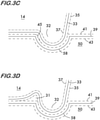
- FIG. 3C and 3D The effect of manufacturing tolerances on the key/groove interface is shown by Figures 3C and 3D .
- Each segment segment 14 shown
- the pipe elements pipe element 50 shown
- Design of mechanical joints must accommodate these tolerance windows without interference.
- undesired interference between the projections 30 and 32 and the grooves 58 will occur when both the coupling and the pipe elements are at their acceptable upper tolerance limits.
- Relief grooves 31 eliminate the zone of greatest interference, zone 45, shown in Figure 3C for a coupling at the upper tolerance limit 35 and a pipe element at the upper tolerance limit 41.
- the fit between arcuate projection 32 and groove 58 in this case is such that the upper tolerance limit line 35 of the coupling is shown interfering with (i.e. passing beneath) the upper tolerance limit line 41 of the pipe element.
- the presence of the relief groove eliminates this interference and allows for a more consistent fit of the arcuate projections, 30, 32 within the groove 58.
- zones of interference 45 would either cause additional stresses to be created in pipe elements 48, 50 as the coupling 10, which is manufactured from metal, attempted to crush the corner of polymeric pipe elements 48, 50 within the zone, or would prevent the arcuate projections 30 and 32 from seating as deeply in groove 58 as possible.
- FIG. 5 Operation of the combination coupling and pipe element is illustrated in Figures 5 and 6 .
- the coupling 10 is shown in a "pre-assembled state" as it would be supplied from the factory or distributor.
- the segments 12 and 14 are attached to one another end to end by the adjustable attachment members 18 (in this example lugs 20 and fasteners 24), but also supported in spaced apart relation by a ring seal 74 positioned between them.
- the ring seal 74 is formed of an elastomer such as EPDM and, when undeformed, has an outer surface 75 (see Figure 4 ) sized to support the segments 12 and 14 in spaced apart relation sufficient to permit insertion of pipe elements 48 and 50 into the central space 16 without disassembling the coupling 10.
- the adjustable attachment members 18 hold the segments 12 and 14 in contact with the ring seal 74 (see Figures 1 and 5 ) in the pre-assembled state and may be adjusted to slightly compress the ring seal 74 so that the segments are not loose. Insertion of the pipe elements, as illustrated in Figure 5 , is aided by the clearance relief regions, in this example, surfaces of increasing radius of curvature 42 (see Figures 1 and 2 ) located adjacent to the ends of segments 12 and 14. The surfaces of increasing radius of curvature 42 provide clearance in the regions of the arcuate projections 30 and 32 which might otherwise interfere with the pipe elements 48 and 50 upon insertion.
- the fasteners 24 are tightened to draw the segments 12 and 14 toward one another and draw the arcuate projections into engagement with the grooves 58 in the pipe elements 48 and 50 and form a pipe joint.
- relief grooves 31 reduce or eliminate the adverse effects of the combined tolerances of the pipe elements 48, 50 and segments 12, 14, allowing increased fatigue life and maximum load when tensile loads are applied as well as when tolerance conditions depart from nominal.
- the relief grooves 31 also prevent the interference (which would otherwise be present) from adding stress to pipe elements 48, 50.
- the ring seal 74 is compressed and deformed between the segments and the pipe elements 48 and 50 and forms a fluid tight joint.
- Relief grooves 31 further permit an increase in the bending rigidity of the joint formed. Bending rigidity is provided by contact between the pipe elements and the segment's shoulders 33 which have a radius of curvature approximately equal to the radius of curvature of the pipe element's outer surface. The relief grooves 31 avoid the interference at corner 45 (see Figure 3D ) and permit full contact between the pipe elements and the shoulders 33, thereby increasing the bending rigidity of the joint formed.
Landscapes
- Engineering & Computer Science (AREA)
- General Engineering & Computer Science (AREA)
- Mechanical Engineering (AREA)
- Fluid Mechanics (AREA)
- Physics & Mathematics (AREA)
- Mutual Connection Of Rods And Tubes (AREA)
- Quick-Acting Or Multi-Walled Pipe Joints (AREA)
- Lining Or Joining Of Plastics Or The Like (AREA)
- Body Structure For Vehicles (AREA)
- Joints With Sleeves (AREA)
- Laminated Bodies (AREA)
- Shaping Of Tube Ends By Bending Or Straightening (AREA)
- Rolls And Other Rotary Bodies (AREA)
- Connection Of Plates (AREA)
- Rigid Pipes And Flexible Pipes (AREA)
- Plural Heterocyclic Compounds (AREA)
- Electroluminescent Light Sources (AREA)
Priority Applications (3)
| Application Number | Priority Date | Filing Date | Title |
|---|---|---|---|
| PL17893518T PL3574244T3 (pl) | 2017-01-24 | 2017-09-07 | Złączka do łączenia elementów rurowych |
| PL20158673T PL3693646T3 (pl) | 2017-01-24 | 2017-09-07 | Złączka o obwodowym kształcie rowka, element rurowy i złączka |
| EP20158673.2A EP3693646B1 (en) | 2017-01-24 | 2017-09-07 | Coupling with circumferential groove shape, pipe element and coupling |
Applications Claiming Priority (2)
| Application Number | Priority Date | Filing Date | Title |
|---|---|---|---|
| US201762449765P | 2017-01-24 | 2017-01-24 | |
| PCT/US2017/050416 WO2018140087A1 (en) | 2017-01-24 | 2017-09-07 | Coupling and circumferential groove shape |
Related Child Applications (2)
| Application Number | Title | Priority Date | Filing Date |
|---|---|---|---|
| EP20158673.2A Division-Into EP3693646B1 (en) | 2017-01-24 | 2017-09-07 | Coupling with circumferential groove shape, pipe element and coupling |
| EP20158673.2A Division EP3693646B1 (en) | 2017-01-24 | 2017-09-07 | Coupling with circumferential groove shape, pipe element and coupling |
Publications (3)
| Publication Number | Publication Date |
|---|---|
| EP3574244A1 EP3574244A1 (en) | 2019-12-04 |
| EP3574244A4 EP3574244A4 (en) | 2020-10-28 |
| EP3574244B1 true EP3574244B1 (en) | 2022-03-23 |
Family
ID=62905785
Family Applications (2)
| Application Number | Title | Priority Date | Filing Date |
|---|---|---|---|
| EP17893518.5A Active EP3574244B1 (en) | 2017-01-24 | 2017-09-07 | Coupling for connecting pipe elements |
| EP20158673.2A Active EP3693646B1 (en) | 2017-01-24 | 2017-09-07 | Coupling with circumferential groove shape, pipe element and coupling |
Family Applications After (1)
| Application Number | Title | Priority Date | Filing Date |
|---|---|---|---|
| EP20158673.2A Active EP3693646B1 (en) | 2017-01-24 | 2017-09-07 | Coupling with circumferential groove shape, pipe element and coupling |
Country Status (23)
| Country | Link |
|---|---|
| US (3) | US10190707B2 (pl) |
| EP (2) | EP3574244B1 (pl) |
| JP (2) | JP7129985B2 (pl) |
| KR (4) | KR102507498B1 (pl) |
| CN (1) | CN110177970B (pl) |
| AU (1) | AU2017395695B2 (pl) |
| BR (2) | BR122019012787B1 (pl) |
| CA (1) | CA3049958C (pl) |
| CL (1) | CL2020002377A1 (pl) |
| CO (1) | CO2019007752A2 (pl) |
| ES (2) | ES2911033T3 (pl) |
| MA (1) | MA45891B1 (pl) |
| MX (2) | MX2019008730A (pl) |
| MY (1) | MY196732A (pl) |
| NZ (1) | NZ753435A (pl) |
| PE (3) | PE20240516A1 (pl) |
| PH (2) | PH12022550826A1 (pl) |
| PL (2) | PL3574244T3 (pl) |
| RU (1) | RU2718944C1 (pl) |
| SA (1) | SA519401973B1 (pl) |
| TW (1) | TWI684723B (pl) |
| WO (1) | WO2018140087A1 (pl) |
| ZA (1) | ZA202508764B (pl) |
Families Citing this family (31)
| Publication number | Priority date | Publication date | Assignee | Title |
|---|---|---|---|---|
| CA3019553A1 (en) * | 2016-03-30 | 2017-10-05 | Hydra-Zorb | Insulated riser clamp |
| JP6865289B2 (ja) * | 2017-02-02 | 2021-04-28 | ビクターリック カンパニー | 機械的および構造的な管類に対する機械的結合具 |
| USD865919S1 (en) * | 2018-01-08 | 2019-11-05 | Tyco Fire Products Lp | Pipe coupling |
| TWI723629B (zh) * | 2018-11-16 | 2021-04-01 | 美商泰科防火產品有限合夥公司 | 快速安裝墊圈之系統及方法 |
| USD909532S1 (en) * | 2018-12-11 | 2021-02-02 | Armaturenwerk Hoetensleben Gmbh | Nozzle |
| USD897494S1 (en) * | 2018-12-11 | 2020-09-29 | Armaturenwerk Hoetensleben Gmbh | Nozzle |
| USD897195S1 (en) * | 2019-02-28 | 2020-09-29 | Victaulic Company | Ring and gusset coupling |
| USD900283S1 (en) * | 2019-03-05 | 2020-10-27 | The Fountainhead Group, Inc. | Adapter for a liquid spray nozzle |
| USD911489S1 (en) * | 2019-03-05 | 2021-02-23 | The Fountainhead Group, Inc. | Liquid spray nozzle |
| USD936785S1 (en) * | 2019-03-05 | 2021-11-23 | The Fountainhead Group, Inc. | Adapter for a liquid spray nozzle |
| USD883445S1 (en) * | 2019-03-05 | 2020-05-05 | The Fountainhead Group, Inc. | Adapter for a liquid spray nozzle with a weed guard |
| USD883446S1 (en) * | 2019-03-05 | 2020-05-05 | The Fountainhead Group, Inc. | Adapter for a liquid spray nozzle |
| USD903835S1 (en) * | 2019-03-28 | 2020-12-01 | Victaulic Company | Coupling segment |
| USD903834S1 (en) * | 2019-03-28 | 2020-12-01 | Victaulic Company | Coupling segment |
| USD886943S1 (en) * | 2019-03-28 | 2020-06-09 | Outdoor Trading LLC | Nozzle |
| USD903833S1 (en) * | 2019-03-28 | 2020-12-01 | Victaulic Company | Coupling segment |
| CA3044273A1 (en) * | 2019-05-27 | 2020-11-27 | Darcy L. Beaumont | Advanced coupling system |
| CN110863892B (zh) * | 2019-11-25 | 2021-01-05 | 安徽江淮汽车集团股份有限公司 | 排气管连接结构 |
| US11788363B2 (en) * | 2020-04-02 | 2023-10-17 | Noetic Technologies Inc. | Tool joint clamp |
| CN111350887B (zh) * | 2020-04-13 | 2021-12-07 | 江苏金泰新减速机有限公司 | 一种工业输送工程中用的导管无缝连接装置 |
| CN111577957A (zh) * | 2020-05-31 | 2020-08-25 | 郝赫 | 一种便于维修的阀门 |
| USD1012228S1 (en) * | 2020-08-31 | 2024-01-23 | X-Virus Llc | Disinfectant misting fixture |
| IL302686A (en) * | 2020-11-11 | 2023-07-01 | Victaulic Co Of America | torque absorbing surface |
| USD1030670S1 (en) * | 2021-06-17 | 2024-06-11 | Telebrands Corp. | Connector |
| KR20250174110A (ko) | 2021-10-01 | 2025-12-11 | 빅톨릭 컴패니 | 안정성이 향상된 가스킷 및 커플링 |
| USD1032783S1 (en) * | 2021-11-10 | 2024-06-25 | Telebrands Corp. | Nozzle |
| US12181083B2 (en) | 2022-07-21 | 2024-12-31 | Applied System Technologies, Inc. | Pipe coupling |
| USD1043909S1 (en) * | 2022-11-11 | 2024-09-24 | Winston Products Llc | Nozzle |
| USD1065441S1 (en) * | 2023-07-03 | 2025-03-04 | Ningbo Tycoon Import And Export Co., Ltd. | Sprayer |
| KR102700794B1 (ko) | 2023-07-24 | 2024-09-02 | 홍순삼 | 이경관 이음용 그루브 커플링 조립체 |
| USD1120211S1 (en) * | 2024-01-24 | 2026-03-24 | Demaclenko It S.R.L. | Snow gun |
Citations (1)
| Publication number | Priority date | Publication date | Assignee | Title |
|---|---|---|---|---|
| GB2516452A (en) * | 2013-07-22 | 2015-01-28 | Jcco 331 Ltd | Improvements in and relating to pipe coupling |
Family Cites Families (36)
| Publication number | Priority date | Publication date | Assignee | Title |
|---|---|---|---|---|
| US2821415A (en) | 1953-04-09 | 1958-01-28 | Race & Race Inc | Grooved and internally reinforced pipe end |
| US3015502A (en) | 1957-11-29 | 1962-01-02 | Victaulic Co Of America | Grooved tubing for connection with sleeve type coupling |
| US3054629A (en) * | 1958-09-04 | 1962-09-18 | Victaulic Co Of America | Pipe couplings |
| DE1289696B (de) * | 1966-05-24 | 1969-02-20 | Mannesmann Ag | Losflanschverbindung fuer Druckrohrleitungen |
| JPS5441124B2 (pl) | 1974-02-01 | 1979-12-06 | ||
| JPS5811115U (ja) * | 1981-07-14 | 1983-01-24 | 三菱自動車工業株式会社 | 樹脂製座付きブツシユ |
| US4702499A (en) * | 1986-10-21 | 1987-10-27 | Victaulic Company Of America | Hingeable segmented pipe couplings |
| US4750762A (en) * | 1987-01-12 | 1988-06-14 | Corzine George S | Axially split clamp for push-on couplings |
| SU1702877A3 (ru) * | 1989-08-17 | 1991-12-30 | Г.А. Струнгис | Разъемное неподвижное уплотнительное устройство |
| JPH06341577A (ja) * | 1990-12-20 | 1994-12-13 | Kurano Seisakusho:Kk | グループ式パイプ配設方法 |
| JP3306502B2 (ja) * | 1994-11-15 | 2002-07-24 | コスモ工機株式会社 | 分岐サドル |
| KR100257340B1 (ko) * | 1997-08-22 | 2000-05-15 | 이종학 | 수도용 내충격성 경질 염화비닐관의 이음 구조체 및 이음 방법 |
| JP3907841B2 (ja) * | 1997-12-25 | 2007-04-18 | 日本ヴィクトリック株式会社 | ハウジング形管継手 |
| US6196039B1 (en) * | 1999-03-25 | 2001-03-06 | Anvil International, Inc. | Groove rolling of piping elements |
| JP3797534B2 (ja) | 2000-02-18 | 2006-07-19 | 川口工業株式会社 | 管体の連結構造 |
| CN2556454Y (zh) * | 2002-07-18 | 2003-06-18 | 川口工业株式会社 | 管体接头 |
| JP4654181B2 (ja) * | 2003-04-25 | 2011-03-16 | ビクトリック カンパニー | パイプ連結器のガスケット及び、これが組み込まれたパイプ連結器 |
| JP2005049281A (ja) * | 2003-07-30 | 2005-02-24 | Denso Corp | 物体認識装置、及び物体認識方法 |
| WO2005094292A2 (en) * | 2004-03-26 | 2005-10-13 | Victaulic Company Of America | Pipe coupling having wedge shaped keys |
| US8267432B2 (en) * | 2004-03-26 | 2012-09-18 | Victaulic Company | Coupling having angularly oriented key surfaces |
| US7086131B2 (en) | 2004-05-14 | 2006-08-08 | Victaulic Company | Deformable mechanical pipe coupling |
| ES2419305T3 (es) * | 2005-02-18 | 2013-08-20 | John Julian Henry | Una abrazadera de acoplamiento de tubos |
| US8136847B2 (en) * | 2009-05-14 | 2012-03-20 | Victaulic Company | Coupling having angularly oriented shoulder surfaces |
| JP4500882B1 (ja) | 2009-12-14 | 2010-07-14 | 日本ヴィクトリック株式会社 | ハウジング形管継手 |
| WO2011074498A1 (ja) * | 2009-12-14 | 2011-06-23 | 日本ヴィクトリック株式会社 | ハウジング形管継手 |
| WO2012116183A1 (en) * | 2011-02-24 | 2012-08-30 | Coupling Solutions, Llc | Pipe coupling assembly with sleeve locking tabs and associated methods |
| US8556302B2 (en) * | 2011-04-05 | 2013-10-15 | Victaulic Company | Pivoting pipe coupling having a movable gripping body |
| EP2750815B1 (en) | 2011-09-02 | 2015-07-22 | Victaulic Company | Spin forming method and device |
| US9194516B2 (en) * | 2012-01-20 | 2015-11-24 | Mueller International, Llc | Slip-on coupling |
| JP5727663B1 (ja) * | 2013-11-18 | 2015-06-03 | 日新製鋼株式会社 | 流体送給管の継手部の転造加工方法および流体送給管 |
| US9951896B2 (en) | 2014-01-17 | 2018-04-24 | Georg Fischer Central Plastics Llc | Pipe couplers and methods |
| WO2018105798A1 (ko) * | 2016-12-09 | 2018-06-14 | 주식회사 원대티지케이 | 이동 스토퍼를 포함하는 가스켓 |
| US10641419B2 (en) | 2016-12-14 | 2020-05-05 | Anvil International, Llc | Pipe coupling with closed ring |
| US11378208B2 (en) | 2016-12-14 | 2022-07-05 | ASC Engineered Solutions, LLC | Pipe couplings |
| KR101968589B1 (ko) * | 2017-05-31 | 2019-08-13 | 강한표 | 그루브드 커플러 |
| CN112728237A (zh) * | 2021-01-05 | 2021-04-30 | 新昌县广远管业有限公司 | 一种自来水内衬复合管的密封装置 |
-
2017
- 2017-09-02 PE PE2024000061A patent/PE20240516A1/es unknown
- 2017-09-07 ES ES17893518T patent/ES2911033T3/es active Active
- 2017-09-07 MY MYPI2019002793A patent/MY196732A/en unknown
- 2017-09-07 MX MX2019008730A patent/MX2019008730A/es unknown
- 2017-09-07 BR BR122019012787-5A patent/BR122019012787B1/pt active IP Right Grant
- 2017-09-07 PH PH1/2022/550826A patent/PH12022550826A1/en unknown
- 2017-09-07 JP JP2019537818A patent/JP7129985B2/ja active Active
- 2017-09-07 KR KR1020227027006A patent/KR102507498B1/ko active Active
- 2017-09-07 PL PL17893518T patent/PL3574244T3/pl unknown
- 2017-09-07 US US15/697,701 patent/US10190707B2/en active Active
- 2017-09-07 EP EP17893518.5A patent/EP3574244B1/en active Active
- 2017-09-07 MA MA45891A patent/MA45891B1/fr unknown
- 2017-09-07 NZ NZ753435A patent/NZ753435A/en unknown
- 2017-09-07 KR KR1020227022180A patent/KR102430773B1/ko active Active
- 2017-09-07 KR KR1020217007772A patent/KR102416212B1/ko active Active
- 2017-09-07 KR KR1020197020124A patent/KR20190094413A/ko not_active Ceased
- 2017-09-07 EP EP20158673.2A patent/EP3693646B1/en active Active
- 2017-09-07 BR BR112019010203-5A patent/BR112019010203B1/pt active IP Right Grant
- 2017-09-07 ES ES20158673T patent/ES2882815T3/es active Active
- 2017-09-07 CN CN201780084368.2A patent/CN110177970B/zh active Active
- 2017-09-07 PE PE2019001471A patent/PE20191278A1/es unknown
- 2017-09-07 WO PCT/US2017/050416 patent/WO2018140087A1/en not_active Ceased
- 2017-09-07 PL PL20158673T patent/PL3693646T3/pl unknown
- 2017-09-07 CA CA3049958A patent/CA3049958C/en active Active
- 2017-09-07 RU RU2019126499A patent/RU2718944C1/ru active
- 2017-09-07 PE PE2024000873A patent/PE20241148A1/es unknown
- 2017-09-07 AU AU2017395695A patent/AU2017395695B2/en active Active
- 2017-10-23 TW TW106136284A patent/TWI684723B/zh active
-
2018
- 2018-11-08 US US16/184,347 patent/US11346472B2/en active Active
-
2019
- 2019-05-31 PH PH12019501226A patent/PH12019501226A1/en unknown
- 2019-06-10 SA SA519401973A patent/SA519401973B1/ar unknown
- 2019-07-18 CO CONC2019/0007752A patent/CO2019007752A2/es unknown
- 2019-07-23 MX MX2023004111A patent/MX2023004111A/es unknown
-
2020
- 2020-09-14 CL CL2020002377A patent/CL2020002377A1/es unknown
-
2021
- 2021-08-31 JP JP2021140801A patent/JP2021191974A/ja not_active Withdrawn
-
2022
- 2022-01-11 US US17/572,743 patent/US12595865B2/en active Active
-
2025
- 2025-10-17 ZA ZA2025/08764A patent/ZA202508764B/en unknown
Patent Citations (1)
| Publication number | Priority date | Publication date | Assignee | Title |
|---|---|---|---|---|
| GB2516452A (en) * | 2013-07-22 | 2015-01-28 | Jcco 331 Ltd | Improvements in and relating to pipe coupling |
Also Published As
Similar Documents
| Publication | Publication Date | Title |
|---|---|---|
| EP3574244B1 (en) | Coupling for connecting pipe elements | |
| AU2018214548B2 (en) | Mechanical coupling for mechanical and structural tubing | |
| EP2100069B1 (en) | Coupling with concave bearing surface | |
| US20190017635A1 (en) | Pipe couplings | |
| SG182321A1 (en) | Coupling having angularly oriented key surfaces | |
| US20150260318A1 (en) | Pipe connector | |
| JP6422843B2 (ja) | 管状構造物及びその製造方法 | |
| KR101488337B1 (ko) | 커플링 | |
| HK40006647B (en) | Coupling, pipe element, and the combination thereof | |
| HK40006647A (en) | Coupling, pipe element, and the combination thereof | |
| CN105378359A (zh) | 用于构造钻孔和操作油气井的螺纹连接件的组件、螺纹连接件、以及用于构造这种螺纹连接件的方法 | |
| JP3229134U (ja) | 金属管の接続構造 | |
| RU2290559C2 (ru) | Самоуплотняющееся соединение трубопроводов |
Legal Events
| Date | Code | Title | Description |
|---|---|---|---|
| STAA | Information on the status of an ep patent application or granted ep patent |
Free format text: STATUS: THE INTERNATIONAL PUBLICATION HAS BEEN MADE |
|
| PUAI | Public reference made under article 153(3) epc to a published international application that has entered the european phase |
Free format text: ORIGINAL CODE: 0009012 |
|
| STAA | Information on the status of an ep patent application or granted ep patent |
Free format text: STATUS: REQUEST FOR EXAMINATION WAS MADE |
|
| 17P | Request for examination filed |
Effective date: 20190813 |
|
| AK | Designated contracting states |
Kind code of ref document: A1 Designated state(s): AL AT BE BG CH CY CZ DE DK EE ES FI FR GB GR HR HU IE IS IT LI LT LU LV MC MK MT NL NO PL PT RO RS SE SI SK SM TR |
|
| AX | Request for extension of the european patent |
Extension state: BA ME |
|
| DAV | Request for validation of the european patent (deleted) | ||
| DAX | Request for extension of the european patent (deleted) | ||
| A4 | Supplementary search report drawn up and despatched |
Effective date: 20200925 |
|
| RIC1 | Information provided on ipc code assigned before grant |
Ipc: F16L 21/03 20060101ALI20200921BHEP Ipc: F16L 17/04 20060101ALI20200921BHEP Ipc: F16L 23/18 20060101ALI20200921BHEP Ipc: F16L 21/02 20060101ALI20200921BHEP Ipc: F16L 23/00 20060101ALI20200921BHEP Ipc: F16L 21/06 20060101AFI20200921BHEP Ipc: F16L 21/00 20060101ALI20200921BHEP |
|
| STAA | Information on the status of an ep patent application or granted ep patent |
Free format text: STATUS: EXAMINATION IS IN PROGRESS |
|
| 17Q | First examination report despatched |
Effective date: 20210312 |
|
| GRAP | Despatch of communication of intention to grant a patent |
Free format text: ORIGINAL CODE: EPIDOSNIGR1 |
|
| STAA | Information on the status of an ep patent application or granted ep patent |
Free format text: STATUS: GRANT OF PATENT IS INTENDED |
|
| INTG | Intention to grant announced |
Effective date: 20220104 |
|
| GRAS | Grant fee paid |
Free format text: ORIGINAL CODE: EPIDOSNIGR3 |
|
| GRAA | (expected) grant |
Free format text: ORIGINAL CODE: 0009210 |
|
| STAA | Information on the status of an ep patent application or granted ep patent |
Free format text: STATUS: THE PATENT HAS BEEN GRANTED |
|
| AK | Designated contracting states |
Kind code of ref document: B1 Designated state(s): AL AT BE BG CH CY CZ DE DK EE ES FI FR GB GR HR HU IE IS IT LI LT LU LV MC MK MT NL NO PL PT RO RS SE SI SK SM TR |
|
| REG | Reference to a national code |
Ref country code: GB Ref legal event code: FG4D |
|
| REG | Reference to a national code |
Ref country code: CH Ref legal event code: EP |
|
| REG | Reference to a national code |
Ref country code: IE Ref legal event code: FG4D |
|
| REG | Reference to a national code |
Ref country code: DE Ref legal event code: R096 Ref document number: 602017055077 Country of ref document: DE |
|
| REG | Reference to a national code |
Ref country code: AT Ref legal event code: REF Ref document number: 1477665 Country of ref document: AT Kind code of ref document: T Effective date: 20220415 |
|
| REG | Reference to a national code |
Ref country code: NL Ref legal event code: FP |
|
| REG | Reference to a national code |
Ref country code: ES Ref legal event code: FG2A Ref document number: 2911033 Country of ref document: ES Kind code of ref document: T3 Effective date: 20220517 |
|
| REG | Reference to a national code |
Ref country code: NO Ref legal event code: T2 Effective date: 20220323 |
|
| REG | Reference to a national code |
Ref country code: LT Ref legal event code: MG9D |
|
| PG25 | Lapsed in a contracting state [announced via postgrant information from national office to epo] |
Ref country code: SE Free format text: LAPSE BECAUSE OF FAILURE TO SUBMIT A TRANSLATION OF THE DESCRIPTION OR TO PAY THE FEE WITHIN THE PRESCRIBED TIME-LIMIT Effective date: 20220323 Ref country code: RS Free format text: LAPSE BECAUSE OF FAILURE TO SUBMIT A TRANSLATION OF THE DESCRIPTION OR TO PAY THE FEE WITHIN THE PRESCRIBED TIME-LIMIT Effective date: 20220323 Ref country code: LT Free format text: LAPSE BECAUSE OF FAILURE TO SUBMIT A TRANSLATION OF THE DESCRIPTION OR TO PAY THE FEE WITHIN THE PRESCRIBED TIME-LIMIT Effective date: 20220323 Ref country code: HR Free format text: LAPSE BECAUSE OF FAILURE TO SUBMIT A TRANSLATION OF THE DESCRIPTION OR TO PAY THE FEE WITHIN THE PRESCRIBED TIME-LIMIT Effective date: 20220323 Ref country code: BG Free format text: LAPSE BECAUSE OF FAILURE TO SUBMIT A TRANSLATION OF THE DESCRIPTION OR TO PAY THE FEE WITHIN THE PRESCRIBED TIME-LIMIT Effective date: 20220623 |
|
| REG | Reference to a national code |
Ref country code: AT Ref legal event code: MK05 Ref document number: 1477665 Country of ref document: AT Kind code of ref document: T Effective date: 20220323 |
|
| PG25 | Lapsed in a contracting state [announced via postgrant information from national office to epo] |
Ref country code: LV Free format text: LAPSE BECAUSE OF FAILURE TO SUBMIT A TRANSLATION OF THE DESCRIPTION OR TO PAY THE FEE WITHIN THE PRESCRIBED TIME-LIMIT Effective date: 20220323 Ref country code: GR Free format text: LAPSE BECAUSE OF FAILURE TO SUBMIT A TRANSLATION OF THE DESCRIPTION OR TO PAY THE FEE WITHIN THE PRESCRIBED TIME-LIMIT Effective date: 20220624 Ref country code: FI Free format text: LAPSE BECAUSE OF FAILURE TO SUBMIT A TRANSLATION OF THE DESCRIPTION OR TO PAY THE FEE WITHIN THE PRESCRIBED TIME-LIMIT Effective date: 20220323 |
|
| PG25 | Lapsed in a contracting state [announced via postgrant information from national office to epo] |
Ref country code: SM Free format text: LAPSE BECAUSE OF FAILURE TO SUBMIT A TRANSLATION OF THE DESCRIPTION OR TO PAY THE FEE WITHIN THE PRESCRIBED TIME-LIMIT Effective date: 20220323 Ref country code: SK Free format text: LAPSE BECAUSE OF FAILURE TO SUBMIT A TRANSLATION OF THE DESCRIPTION OR TO PAY THE FEE WITHIN THE PRESCRIBED TIME-LIMIT Effective date: 20220323 Ref country code: RO Free format text: LAPSE BECAUSE OF FAILURE TO SUBMIT A TRANSLATION OF THE DESCRIPTION OR TO PAY THE FEE WITHIN THE PRESCRIBED TIME-LIMIT Effective date: 20220323 Ref country code: PT Free format text: LAPSE BECAUSE OF FAILURE TO SUBMIT A TRANSLATION OF THE DESCRIPTION OR TO PAY THE FEE WITHIN THE PRESCRIBED TIME-LIMIT Effective date: 20220725 Ref country code: EE Free format text: LAPSE BECAUSE OF FAILURE TO SUBMIT A TRANSLATION OF THE DESCRIPTION OR TO PAY THE FEE WITHIN THE PRESCRIBED TIME-LIMIT Effective date: 20220323 Ref country code: CZ Free format text: LAPSE BECAUSE OF FAILURE TO SUBMIT A TRANSLATION OF THE DESCRIPTION OR TO PAY THE FEE WITHIN THE PRESCRIBED TIME-LIMIT Effective date: 20220323 Ref country code: AT Free format text: LAPSE BECAUSE OF FAILURE TO SUBMIT A TRANSLATION OF THE DESCRIPTION OR TO PAY THE FEE WITHIN THE PRESCRIBED TIME-LIMIT Effective date: 20220323 |
|
| PG25 | Lapsed in a contracting state [announced via postgrant information from national office to epo] |
Ref country code: IS Free format text: LAPSE BECAUSE OF FAILURE TO SUBMIT A TRANSLATION OF THE DESCRIPTION OR TO PAY THE FEE WITHIN THE PRESCRIBED TIME-LIMIT Effective date: 20220723 Ref country code: AL Free format text: LAPSE BECAUSE OF FAILURE TO SUBMIT A TRANSLATION OF THE DESCRIPTION OR TO PAY THE FEE WITHIN THE PRESCRIBED TIME-LIMIT Effective date: 20220323 |
|
| REG | Reference to a national code |
Ref country code: DE Ref legal event code: R097 Ref document number: 602017055077 Country of ref document: DE |
|
| PLBE | No opposition filed within time limit |
Free format text: ORIGINAL CODE: 0009261 |
|
| STAA | Information on the status of an ep patent application or granted ep patent |
Free format text: STATUS: NO OPPOSITION FILED WITHIN TIME LIMIT |
|
| PG25 | Lapsed in a contracting state [announced via postgrant information from national office to epo] |
Ref country code: DK Free format text: LAPSE BECAUSE OF FAILURE TO SUBMIT A TRANSLATION OF THE DESCRIPTION OR TO PAY THE FEE WITHIN THE PRESCRIBED TIME-LIMIT Effective date: 20220323 |
|
| 26N | No opposition filed |
Effective date: 20230102 |
|
| PG25 | Lapsed in a contracting state [announced via postgrant information from national office to epo] |
Ref country code: MC Free format text: LAPSE BECAUSE OF FAILURE TO SUBMIT A TRANSLATION OF THE DESCRIPTION OR TO PAY THE FEE WITHIN THE PRESCRIBED TIME-LIMIT Effective date: 20220323 |
|
| REG | Reference to a national code |
Ref country code: CH Ref legal event code: PL |
|
| PG25 | Lapsed in a contracting state [announced via postgrant information from national office to epo] |
Ref country code: SI Free format text: LAPSE BECAUSE OF FAILURE TO SUBMIT A TRANSLATION OF THE DESCRIPTION OR TO PAY THE FEE WITHIN THE PRESCRIBED TIME-LIMIT Effective date: 20220323 |
|
| PG25 | Lapsed in a contracting state [announced via postgrant information from national office to epo] |
Ref country code: LU Free format text: LAPSE BECAUSE OF NON-PAYMENT OF DUE FEES Effective date: 20220907 |
|
| P01 | Opt-out of the competence of the unified patent court (upc) registered |
Effective date: 20230619 |
|
| PG25 | Lapsed in a contracting state [announced via postgrant information from national office to epo] |
Ref country code: LI Free format text: LAPSE BECAUSE OF NON-PAYMENT OF DUE FEES Effective date: 20220930 Ref country code: IT Free format text: LAPSE BECAUSE OF FAILURE TO SUBMIT A TRANSLATION OF THE DESCRIPTION OR TO PAY THE FEE WITHIN THE PRESCRIBED TIME-LIMIT Effective date: 20220323 Ref country code: IE Free format text: LAPSE BECAUSE OF NON-PAYMENT OF DUE FEES Effective date: 20220907 Ref country code: CH Free format text: LAPSE BECAUSE OF NON-PAYMENT OF DUE FEES Effective date: 20220930 |
|
| PG25 | Lapsed in a contracting state [announced via postgrant information from national office to epo] |
Ref country code: HU Free format text: LAPSE BECAUSE OF FAILURE TO SUBMIT A TRANSLATION OF THE DESCRIPTION OR TO PAY THE FEE WITHIN THE PRESCRIBED TIME-LIMIT; INVALID AB INITIO Effective date: 20170907 |
|
| PG25 | Lapsed in a contracting state [announced via postgrant information from national office to epo] |
Ref country code: CY Free format text: LAPSE BECAUSE OF FAILURE TO SUBMIT A TRANSLATION OF THE DESCRIPTION OR TO PAY THE FEE WITHIN THE PRESCRIBED TIME-LIMIT Effective date: 20220323 |
|
| PG25 | Lapsed in a contracting state [announced via postgrant information from national office to epo] |
Ref country code: MK Free format text: LAPSE BECAUSE OF FAILURE TO SUBMIT A TRANSLATION OF THE DESCRIPTION OR TO PAY THE FEE WITHIN THE PRESCRIBED TIME-LIMIT Effective date: 20220323 |
|
| PG25 | Lapsed in a contracting state [announced via postgrant information from national office to epo] |
Ref country code: MT Free format text: LAPSE BECAUSE OF FAILURE TO SUBMIT A TRANSLATION OF THE DESCRIPTION OR TO PAY THE FEE WITHIN THE PRESCRIBED TIME-LIMIT Effective date: 20220323 |
|
| PGFP | Annual fee paid to national office [announced via postgrant information from national office to epo] |
Ref country code: PL Payment date: 20250624 Year of fee payment: 9 |
|
| PGFP | Annual fee paid to national office [announced via postgrant information from national office to epo] |
Ref country code: NL Payment date: 20250812 Year of fee payment: 9 |
|
| PGFP | Annual fee paid to national office [announced via postgrant information from national office to epo] |
Ref country code: DE Payment date: 20250808 Year of fee payment: 9 |
|
| PGFP | Annual fee paid to national office [announced via postgrant information from national office to epo] |
Ref country code: NO Payment date: 20250827 Year of fee payment: 9 |
|
| PGFP | Annual fee paid to national office [announced via postgrant information from national office to epo] |
Ref country code: TR Payment date: 20250820 Year of fee payment: 9 |
|
| PGFP | Annual fee paid to national office [announced via postgrant information from national office to epo] |
Ref country code: BE Payment date: 20250812 Year of fee payment: 9 Ref country code: GB Payment date: 20250814 Year of fee payment: 9 |
|
| PGFP | Annual fee paid to national office [announced via postgrant information from national office to epo] |
Ref country code: FR Payment date: 20250808 Year of fee payment: 9 |
|
| PGFP | Annual fee paid to national office [announced via postgrant information from national office to epo] |
Ref country code: ES Payment date: 20251003 Year of fee payment: 9 |