EP3573169A1 - Batterie mit löschvorrichtung und kraftfahrzeug - Google Patents
Batterie mit löschvorrichtung und kraftfahrzeug Download PDFInfo
- Publication number
- EP3573169A1 EP3573169A1 EP19175630.3A EP19175630A EP3573169A1 EP 3573169 A1 EP3573169 A1 EP 3573169A1 EP 19175630 A EP19175630 A EP 19175630A EP 3573169 A1 EP3573169 A1 EP 3573169A1
- Authority
- EP
- European Patent Office
- Prior art keywords
- battery
- extinguishing agent
- wall
- reservoir
- battery cell
- Prior art date
- Legal status (The legal status is an assumption and is not a legal conclusion. Google has not performed a legal analysis and makes no representation as to the accuracy of the status listed.)
- Granted
Links
Images

Classifications
-
- B—PERFORMING OPERATIONS; TRANSPORTING
- B60—VEHICLES IN GENERAL
- B60L—PROPULSION OF ELECTRICALLY-PROPELLED VEHICLES; SUPPLYING ELECTRIC POWER FOR AUXILIARY EQUIPMENT OF ELECTRICALLY-PROPELLED VEHICLES; ELECTRODYNAMIC BRAKE SYSTEMS FOR VEHICLES IN GENERAL; MAGNETIC SUSPENSION OR LEVITATION FOR VEHICLES; MONITORING OPERATING VARIABLES OF ELECTRICALLY-PROPELLED VEHICLES; ELECTRIC SAFETY DEVICES FOR ELECTRICALLY-PROPELLED VEHICLES
- B60L50/00—Electric propulsion with power supplied within the vehicle
- B60L50/50—Electric propulsion with power supplied within the vehicle using propulsion power supplied by batteries or fuel cells
- B60L50/60—Electric propulsion with power supplied within the vehicle using propulsion power supplied by batteries or fuel cells using power supplied by batteries
- B60L50/64—Constructional details of batteries specially adapted for electric vehicles
-
- A—HUMAN NECESSITIES
- A62—LIFE-SAVING; FIRE-FIGHTING
- A62C—FIRE-FIGHTING
- A62C3/00—Fire prevention, containment or extinguishing specially adapted for particular objects or places
- A62C3/07—Fire prevention, containment or extinguishing specially adapted for particular objects or places in vehicles, e.g. in road vehicles
-
- A—HUMAN NECESSITIES
- A62—LIFE-SAVING; FIRE-FIGHTING
- A62C—FIRE-FIGHTING
- A62C3/00—Fire prevention, containment or extinguishing specially adapted for particular objects or places
- A62C3/16—Fire prevention, containment or extinguishing specially adapted for particular objects or places in electrical installations, e.g. cableways
-
- B—PERFORMING OPERATIONS; TRANSPORTING
- B60—VEHICLES IN GENERAL
- B60L—PROPULSION OF ELECTRICALLY-PROPELLED VEHICLES; SUPPLYING ELECTRIC POWER FOR AUXILIARY EQUIPMENT OF ELECTRICALLY-PROPELLED VEHICLES; ELECTRODYNAMIC BRAKE SYSTEMS FOR VEHICLES IN GENERAL; MAGNETIC SUSPENSION OR LEVITATION FOR VEHICLES; MONITORING OPERATING VARIABLES OF ELECTRICALLY-PROPELLED VEHICLES; ELECTRIC SAFETY DEVICES FOR ELECTRICALLY-PROPELLED VEHICLES
- B60L3/00—Electric devices on electrically-propelled vehicles for safety purposes; Monitoring operating variables, e.g. speed, deceleration or energy consumption
- B60L3/0023—Detecting, eliminating, remedying or compensating for drive train abnormalities, e.g. failures within the drive train
- B60L3/0046—Detecting, eliminating, remedying or compensating for drive train abnormalities, e.g. failures within the drive train relating to electric energy storage systems, e.g. batteries or capacitors
-
- H—ELECTRICITY
- H01—ELECTRIC ELEMENTS
- H01M—PROCESSES OR MEANS, e.g. BATTERIES, FOR THE DIRECT CONVERSION OF CHEMICAL ENERGY INTO ELECTRICAL ENERGY
- H01M10/00—Secondary cells; Manufacture thereof
- H01M10/05—Accumulators with non-aqueous electrolyte
- H01M10/052—Li-accumulators
- H01M10/0525—Rocking-chair batteries, i.e. batteries with lithium insertion or intercalation in both electrodes; Lithium-ion batteries
-
- H—ELECTRICITY
- H01—ELECTRIC ELEMENTS
- H01M—PROCESSES OR MEANS, e.g. BATTERIES, FOR THE DIRECT CONVERSION OF CHEMICAL ENERGY INTO ELECTRICAL ENERGY
- H01M10/00—Secondary cells; Manufacture thereof
- H01M10/42—Methods or arrangements for servicing or maintenance of secondary cells or secondary half-cells
- H01M10/4207—Methods or arrangements for servicing or maintenance of secondary cells or secondary half-cells for several batteries or cells simultaneously or sequentially
-
- H—ELECTRICITY
- H01—ELECTRIC ELEMENTS
- H01M—PROCESSES OR MEANS, e.g. BATTERIES, FOR THE DIRECT CONVERSION OF CHEMICAL ENERGY INTO ELECTRICAL ENERGY
- H01M10/00—Secondary cells; Manufacture thereof
- H01M10/42—Methods or arrangements for servicing or maintenance of secondary cells or secondary half-cells
- H01M10/4235—Safety or regulating additives or arrangements in electrodes, separators or electrolyte
-
- H—ELECTRICITY
- H01—ELECTRIC ELEMENTS
- H01M—PROCESSES OR MEANS, e.g. BATTERIES, FOR THE DIRECT CONVERSION OF CHEMICAL ENERGY INTO ELECTRICAL ENERGY
- H01M10/00—Secondary cells; Manufacture thereof
- H01M10/42—Methods or arrangements for servicing or maintenance of secondary cells or secondary half-cells
- H01M10/425—Structural combination with electronic components, e.g. electronic circuits integrated to the outside of the casing
-
- H—ELECTRICITY
- H01—ELECTRIC ELEMENTS
- H01M—PROCESSES OR MEANS, e.g. BATTERIES, FOR THE DIRECT CONVERSION OF CHEMICAL ENERGY INTO ELECTRICAL ENERGY
- H01M10/00—Secondary cells; Manufacture thereof
- H01M10/42—Methods or arrangements for servicing or maintenance of secondary cells or secondary half-cells
- H01M10/48—Accumulators combined with arrangements for measuring, testing or indicating the condition of cells, e.g. the level or density of the electrolyte
-
- H—ELECTRICITY
- H01—ELECTRIC ELEMENTS
- H01M—PROCESSES OR MEANS, e.g. BATTERIES, FOR THE DIRECT CONVERSION OF CHEMICAL ENERGY INTO ELECTRICAL ENERGY
- H01M10/00—Secondary cells; Manufacture thereof
- H01M10/42—Methods or arrangements for servicing or maintenance of secondary cells or secondary half-cells
- H01M10/48—Accumulators combined with arrangements for measuring, testing or indicating the condition of cells, e.g. the level or density of the electrolyte
- H01M10/486—Accumulators combined with arrangements for measuring, testing or indicating the condition of cells, e.g. the level or density of the electrolyte for measuring temperature
-
- H—ELECTRICITY
- H01—ELECTRIC ELEMENTS
- H01M—PROCESSES OR MEANS, e.g. BATTERIES, FOR THE DIRECT CONVERSION OF CHEMICAL ENERGY INTO ELECTRICAL ENERGY
- H01M10/00—Secondary cells; Manufacture thereof
- H01M10/60—Heating or cooling; Temperature control
- H01M10/65—Means for temperature control structurally associated with the cells
-
- H—ELECTRICITY
- H01—ELECTRIC ELEMENTS
- H01M—PROCESSES OR MEANS, e.g. BATTERIES, FOR THE DIRECT CONVERSION OF CHEMICAL ENERGY INTO ELECTRICAL ENERGY
- H01M50/00—Constructional details or processes of manufacture of the non-active parts of electrochemical cells other than fuel cells, e.g. hybrid cells
- H01M50/20—Mountings; Secondary casings or frames; Racks, modules or packs; Suspension devices; Shock absorbers; Transport or carrying devices; Holders
- H01M50/249—Mountings; Secondary casings or frames; Racks, modules or packs; Suspension devices; Shock absorbers; Transport or carrying devices; Holders specially adapted for aircraft or vehicles, e.g. cars or trains
-
- A—HUMAN NECESSITIES
- A62—LIFE-SAVING; FIRE-FIGHTING
- A62C—FIRE-FIGHTING
- A62C3/00—Fire prevention, containment or extinguishing specially adapted for particular objects or places
-
- H—ELECTRICITY
- H01—ELECTRIC ELEMENTS
- H01M—PROCESSES OR MEANS, e.g. BATTERIES, FOR THE DIRECT CONVERSION OF CHEMICAL ENERGY INTO ELECTRICAL ENERGY
- H01M2200/00—Safety devices for primary or secondary batteries
-
- H—ELECTRICITY
- H01—ELECTRIC ELEMENTS
- H01M—PROCESSES OR MEANS, e.g. BATTERIES, FOR THE DIRECT CONVERSION OF CHEMICAL ENERGY INTO ELECTRICAL ENERGY
- H01M2220/00—Batteries for particular applications
- H01M2220/20—Batteries in motive systems, e.g. vehicle, ship, plane
-
- H—ELECTRICITY
- H01—ELECTRIC ELEMENTS
- H01M—PROCESSES OR MEANS, e.g. BATTERIES, FOR THE DIRECT CONVERSION OF CHEMICAL ENERGY INTO ELECTRICAL ENERGY
- H01M50/00—Constructional details or processes of manufacture of the non-active parts of electrochemical cells other than fuel cells, e.g. hybrid cells
- H01M50/20—Mountings; Secondary casings or frames; Racks, modules or packs; Suspension devices; Shock absorbers; Transport or carrying devices; Holders
- H01M50/204—Racks, modules or packs for multiple batteries or multiple cells
- H01M50/207—Racks, modules or packs for multiple batteries or multiple cells characterised by their shape
- H01M50/209—Racks, modules or packs for multiple batteries or multiple cells characterised by their shape adapted for prismatic or rectangular cells
-
- Y—GENERAL TAGGING OF NEW TECHNOLOGICAL DEVELOPMENTS; GENERAL TAGGING OF CROSS-SECTIONAL TECHNOLOGIES SPANNING OVER SEVERAL SECTIONS OF THE IPC; TECHNICAL SUBJECTS COVERED BY FORMER USPC CROSS-REFERENCE ART COLLECTIONS [XRACs] AND DIGESTS
- Y02—TECHNOLOGIES OR APPLICATIONS FOR MITIGATION OR ADAPTATION AGAINST CLIMATE CHANGE
- Y02E—REDUCTION OF GREENHOUSE GAS [GHG] EMISSIONS, RELATED TO ENERGY GENERATION, TRANSMISSION OR DISTRIBUTION
- Y02E60/00—Enabling technologies; Technologies with a potential or indirect contribution to GHG emissions mitigation
- Y02E60/10—Energy storage using batteries
-
- Y—GENERAL TAGGING OF NEW TECHNOLOGICAL DEVELOPMENTS; GENERAL TAGGING OF CROSS-SECTIONAL TECHNOLOGIES SPANNING OVER SEVERAL SECTIONS OF THE IPC; TECHNICAL SUBJECTS COVERED BY FORMER USPC CROSS-REFERENCE ART COLLECTIONS [XRACs] AND DIGESTS
- Y02—TECHNOLOGIES OR APPLICATIONS FOR MITIGATION OR ADAPTATION AGAINST CLIMATE CHANGE
- Y02T—CLIMATE CHANGE MITIGATION TECHNOLOGIES RELATED TO TRANSPORTATION
- Y02T10/00—Road transport of goods or passengers
- Y02T10/60—Other road transportation technologies with climate change mitigation effect
- Y02T10/70—Energy storage systems for electromobility, e.g. batteries
Definitions
- the present invention relates to a battery with an integrated extinguishing device for a motor vehicle, in particular an electric vehicle or hybrid vehicle. Furthermore, the invention relates to a motor vehicle, in particular an electric vehicle or hybrid vehicle, with a generic battery.
- Fully hybrid vehicles and electric vehicles have at least one electric motor, which is designed to drive the motor vehicle, full hybrid vehicles having, in addition to the electric motor, at least one internal combustion engine for driving the motor vehicle.
- full hybrid vehicles and electric vehicles have a rechargeable battery.
- a range of full hybrid vehicles is at least partially dependent on a storage capacity of the battery.
- the range of electric vehicles is proportional to the storage capacity of the battery. Since motor vehicles have only a limited space for batteries, an increase in the capacity of the battery can only be achieved by increasing the power density or energy density of the battery.
- Li-ion batteries which are referred to below as Li-ion batteries, have a particularly high power density and a relatively large number of possible charging cycles or a particularly small capacity loss per charging cycle. For this reason, Li-ion batteries are now widely used in the automotive industry, especially in full hybrid vehicles and electric vehicles.
- Li-ion batteries of a high energy density is also a major disadvantage of Li-ion batteries, since the high energy density is based essentially on a high reactivity of lithium. Due to the high reactivity of lithium, Li-ion batteries, especially in accident situations, represent a high risk to the environment. As a result of an accident caused plastic deformation of the Li-ion battery For example, lithium can leak out of the Li-ion battery and react explosively with the environment, especially with water. Further, such plastic deformation within the Li-ion battery can cause a short circuit which can overheat the battery and eventually burn or even explode.
- these batteries are protected by a housing, a vehicle structure of the motor vehicle and an underrun protection against external mechanical effects.
- the battery is installed at a point in the motor vehicle to which the risk of damage to the battery is particularly low in the event of a crash.
- the US 9,704,384 B2 relates to a refrigerant leading cooling system for a battery having a plurality of cooling plates.
- the cooling system has injectors for targeted injection of the refrigerant into the battery in the event of a cell damage.
- the thereby occurring expansion of the pressurized refrigerant leads to a local cooling and thus to a damming of the thermal runaway of the battery cells.
- the DE 10 2012 021 095 A1 discloses another extinguishing device for a battery.
- the extinguishing device has an external reservoir for receiving the extinguishing agent, a sensor system for detecting a cell damage and a conduit system for guiding the extinguishing agent into the battery in response to the detection of a damaged battery cell by means of the sensor system.
- the DE 10 2012 214 262 A1 describes a deletion concept for high-voltage batteries in hybrid and electric vehicles.
- the extinguishing system has an extinguishing agent reservoir with a predetermined breaking point, which is arranged within a battery housing. Furthermore, the extinguishing system has a temperature sensor, a control device and an actuator. Upon detecting the exceeding of a limit temperature by the temperature sensor, the actuator is controlled by the control device to the extinguishing agent reservoir at the predetermined breaking point break open and thus release the extinguishing agent.
- the DE 10 2013 216 296 A1 relates to a comparable battery, wherein instead of a temperature sensor, a chemical sensor is used for detecting a damage of a battery cell.
- Known batteries with extinguishing devices have the disadvantage that they have a very complex structure and a complex sensor for detecting damage to battery cells and an actuator for triggering the deletion process is required. Accordingly, the production costs of known batteries with extinguishing devices are particularly high. Furthermore, in particular complex extinguishing devices are very susceptible to interference, so that there is a relatively high residual risk that the extinguishing device is not triggered or at least delayed. As a result, the reliability of a motor vehicle is impaired. Moreover, predetermined breaking points have the disadvantage that they inadvertently fail and thus can release extinguishing agents, although there is no cell damage. The life of the battery can be affected.
- the object is achieved by a battery for a motor vehicle.
- the battery has a battery wall surrounding a battery interior, an arranged in the battery interior extinguishing agent reservoir in which an extinguishing agent is added, and at least one in the battery interior of the extinguishing agent separately arranged battery cell.
- the extinguishing agent reservoir has a reservoir wall for retaining the extinguishing agent.
- the battery is designed such that the reservoir wall has a first wall temperature at a normal operating temperature of the battery cell and a second wall temperature at a limit operating temperature of the battery cell.
- the reservoir wall is designed to maintain a tightness for retaining the extinguishing agent at the first wall temperature and to be destroyed by heat at the second wall temperature.
- the second wall temperature is higher than the first wall temperature.
- the battery wall is designed to protect the battery interior from external influences, in particular from water, dirt and mechanical loads or the like.
- at least one battery cell preferably a plurality of battery cells, are arranged and preferably fixed in position relative to the battery housing.
- the extinguishing agent reservoir is arranged inside the battery interior and sealed in such a way that the extinguishing agent accommodated in the extinguishing agent reservoir remains in the latter during normal operation of the battery. In this way, the battery cells of the battery are protected from the extinguishing agent.
- the extinguishing agent used is preferably the extinguishing agent "Novec 1230®" from 3M®.
- One side of the extinguishing agent reservoir faces at least one battery cell, for example, this, in particular directly, adjacent. A heat emitted by the battery cell can thus be introduced into the reservoir wall.
- the reservoir wall is arranged as close as possible to the battery cell. It may be provided according to the invention that the reservoir wall contacts the battery cell directly or via a thermally conductive intermediate material.
- the normal operating temperature of the battery denotes a temperature range which the battery cell can have in operation without damaging the battery.
- the first wall temperature of the reservoir wall will correspond during operation of the battery to the normal operating temperature or at least substantially correspond.
- the reservoir wall is designed to maintain a structure at the first wall temperature and thus to ensure a secure retention of the extinguishing agent.
- the limit operating temperature of the battery cell denotes a temperature at which a reliability of the battery is no longer guaranteed. From the limit temperature, for example, battery cells can go through or explode.
- the reservoir wall is designed to structurally fail upon reaching the second wall temperature such that the tightness is no longer present and extinguishing agent can pass through the reservoir wall. This can be done, for example, by melting the reservoir wall at the second wall temperature.
- the structural failure is preferably irreversible.
- the second wall temperature is preferably below 180 ° C, in particular between 120 ° C and 160 ° C.
- a battery according to the invention for a motor vehicle has the advantage over conventional batteries of being able to avoid and explode battery cells by simple means and in a cost-effective manner. Due to the nature of the reservoir wall, the reservoir wall is automatically destroyed when a battery cell of the battery reaches the limit operating temperature, so that the overheated battery cell is rapidly cooled or extinguished. An additional sensor and actuator is not required.
- the reservoir wall comprises an elastomer.
- the reservoir wall is at least partially made of an elastomer.
- An elastomer has the advantage that the extinguishing agent reservoir is adaptable to a free space within the battery interior. In this way, a volume of the extinguishing agent reservoir and thus a recordable amount of extinguishing agent can be maximized.
- Another advantage of an elastomer is that a heat flow from the battery cell into the reservoir wall can be improved by the flexibility of the reservoir wall.
- a part of the reservoir wall is formed by the battery wall.
- this part of the reservoir wall has a different constitution than a part of the reservoir wall facing the battery cells.
- a retaining device for retaining the extinguishing agent reservoir from the battery cell arranged.
- the retaining device preferably has a higher rigidity than the reservoir wall, so that by means of the retaining device, a movement limitation is provided to the extinguishing agent reservoir. In this way, for example, inadvertent contacting of the battery cell by the extinguishing agent reservoir can be avoided. Furthermore, inadvertent damage to the extinguishing agent reservoir due to external shocks in an advantageous manner and by simple means can be avoided.
- the retaining device is designed as a perforated plate or grid.
- a perforated plate or grid Such a retaining device has the advantage that when the reservoir wall is damaged due to the second wall temperature, rapid and reliable flow of the extinguishing agent to the battery cell is ensured.
- the retaining device with the battery cell in particular with a side facing away from the retaining device of the battery cell, thermally conductively coupled.
- the retaining device preferably contacts the reservoir wall and the battery cell.
- the retaining device is thermally conductively coupled to a plurality of locations of the battery cell, so that temperatures of different locations of the battery cell can be tapped off.
- a thermal coupling has the advantage that a release of the extinguishing agent is improved upon reaching the limit operating temperature of the battery and has a low delay.
- the heat generated by the battery cell can be selectively conveyed to the reservoir wall, so that a structural failure of predetermined areas of the reservoir wall can be effected.
- a thermal connection to the side facing away from the retaining device of the battery cell has the advantage that a delay in the release of the extinguishing agent is further improved, especially if the battery cell has at least temporarily different temperatures in different areas.
- the retaining device is arranged on an upper side of the battery cell.
- the top of the battery has in the installed state in a motor vehicle upwards. This has the advantage that the extinguishing agent can be conducted by gravity to the battery cell, so that improved deletion or cooling of the battery cell is ensured by simple means and in a cost effective manner.
- the extinguishing agent reservoir is designed as a pressure vessel.
- the introduced into the extinguishing agent reservoir extinguishing agent is preferably under pressure. This has the advantage that, when the reservoir wall is destroyed, the extinguishing agent escapes from the extinguishing agent reservoir very quickly and thus deletes or cools the battery cell particularly quickly and effectively.
- the battery has a pressure sensor for monitoring an internal pressure in the extinguishing agent reservoir. More preferably, the internal pressure in the extinguishing agent reservoir is dependent on the temperature of the extinguishing agent wall, so that the temperature of the extinguishing agent wall can be deduced from the detected pressure of the extinguishing agent. An imminent as well as a completed release of the extinguishing agent can thus be displayed by simple means.
- the object is achieved by a motor vehicle with an electric motor and a battery.
- the battery is designed as a battery according to the invention according to the first aspect of the invention.
- the motor vehicle according to the invention over conventional motor vehicles has the advantage that with simple means and in a cost-effective manner, a runaway and exploding of battery cells can be avoided. Due to the nature of the reservoir wall, the reservoir wall is automatically destroyed when a battery cell of the battery reaches the limit operating temperature, so that the overheated battery cell is rapidly cooled or extinguished. An additional sensor and actuator is not required. In particular, in a crash situation, the motor vehicle according to the invention therefore has a particularly high reliability.
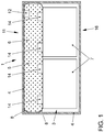
- a preferred first embodiment of a battery 1 according to the invention is shown schematically in a sectional view.
- the battery 1 has a battery wall 4, which surrounds a battery interior 3 and shields to the outside.
- two battery cells 7, in particular on Li-ion-based, are arranged side by side in this example.
- the battery cells 7 each have two electrodes 14, which are aligned to an upper side 11 of the battery 1 out.
- an extinguishing agent reservoir 5 is arranged inside the battery interior 3.
- an extinguishing agent 6 is arranged, which is preferably under excess pressure.
- the battery 1 has a pressure sensor 12, which is arranged within the extinguishing agent reservoir 5.
- the Reservoirwandung 8 is designed to withstand a normal operating temperature of the battery cells 7 and give in reaching or exceeding a limit operating temperature of at least one battery cell 7 and release the extinguishing agent 6 for deleting or cooling the battery cell 7.
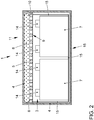
- Fig. 2 shows a preferred second embodiment of a battery 1 according to the invention schematically in a sectional view.
- the battery 1 has a battery wall 4, which surrounds a battery interior 3 and shields to the outside.
- two battery cells 7, in particular on Li-ion-based, are arranged side by side in this example.
- the battery cells 7 each have two electrodes 14, which are aligned to an upper side 11 of the battery 1 out.
- an extinguishing agent reservoir 5 is arranged inside the battery interior 3.
- the battery 1 has a retaining device 9 formed as a perforated plate 10.
- the retaining device 9 preferably has a particularly good thermal conductivity, such as copper.
- the retaining device 9 is thermally coupled via optional thermal conductors 15 to a lower side 16 of the battery cells 7. Heating of the retaining device 9 by the battery cells 7 can thus take place via the thermal conductors 15 and directly by thermal radiation.
- the retaining device 9 a top 11 of the battery cell 7 contacted directly or via another, not shown, thermal conductor 15.
- an extinguishing agent 6 is arranged, which is preferably under overpressure.
- the Reservoirwandung 8 is designed to withstand a normal operating temperature of the battery cells 7 and give in reaching or exceeding a limit operating temperature of at least one battery cell 7 and release the extinguishing agent 6 for extinguishing or cooling the battery cell 7.
- the passage of the extinguishing agent 6 from the extinguishing agent reservoir 5 to the battery cells 7 is favored by the holes formed in the perforated plate 10.
- FIG. 3 an inventive motor vehicle 2 is shown schematically in a side view.
- the motor vehicle 2 has an electric motor 13 and a battery 1 according to the invention, which are indicated in this illustration by dashed lines.
Landscapes
- Engineering & Computer Science (AREA)
- Chemical & Material Sciences (AREA)
- Chemical Kinetics & Catalysis (AREA)
- General Chemical & Material Sciences (AREA)
- Electrochemistry (AREA)
- Manufacturing & Machinery (AREA)
- Power Engineering (AREA)
- Life Sciences & Earth Sciences (AREA)
- Transportation (AREA)
- Mechanical Engineering (AREA)
- Sustainable Energy (AREA)
- Sustainable Development (AREA)
- Health & Medical Sciences (AREA)
- Public Health (AREA)
- Emergency Management (AREA)
- Business, Economics & Management (AREA)
- Aviation & Aerospace Engineering (AREA)
- Materials Engineering (AREA)
- Microelectronics & Electronic Packaging (AREA)
- Battery Mounting, Suspending (AREA)
- Electric Propulsion And Braking For Vehicles (AREA)
Abstract
Description
- Die vorliegende Erfindung betrifft eine Batterie mit einer integrierten Löschvorrichtung für ein Kraftfahrzeug, insbesondere ein Elektrofahrzeug oder Hybridfahrzeug. Ferner betrifft die Erfindung ein Kraftfahrzeug, insbesondere ein Elektrofahrzeug oder Hybridfahrzeug, mit einer gattungsgemäßen Batterie.
- Als umweltfreundliche sowie energiesparende Alternative zu herkömmlichen Kraftfahrzeugen mit einem Verbrennungsmotor gewinnen insbesondere Vollhybridfahrzeuge und Elektrofahrzeuge zunehmend an Bedeutung. Vollhybridfahrzeuge und Elektrofahrzeuge weisen mindestens einen Elektromotor auf, welcher zum Antreiben des Kraftfahrzeugs ausgebildet ist, wobei Vollhybridfahrzeuge zusätzlich zum Elektromotor mindestens einen Verbrennungsmotor zum Antreiben des Kraftfahrzeugs aufweisen.
- Zur Bereitstellung elektrischer Energie zum Betreiben des Elektromotors weisen Vollhybridfahrzeuge und Elektrofahrzeuge eine wiederaufladbare Batterie auf. Eine Reichweite von Vollhybridfahrzeugen ist zumindest teilweise von einer Speicherkapazität der Batterie abhängig. Die Reichweite von Elektrofahrzeugen ist proportional zur Speicherkapazität der Batterie. Da Kraftfahrzeuge nur einen begrenzten Bauraum für Batterien aufweisen, ist eine Vergrößerung der Kapazität der Batterie nur durch eine Erhöhung der Leistungsdichte beziehungsweise Energiedichte der Batterie erzielbar.
- Lithium-Ionen-Batterien, welche im Folgenden als Li-Ion-Batterien bezeichnet werden, weisen eine besonders hohe Leistungsdichte sowie eine relativ große Anzahl möglicher Ladezyklen beziehungsweise einen besonders geringen Kapazitätsverlust pro Ladezyklus auf. Aus diesem Grund sind Li-Ionen-Batterien im Automobilbau, insbesondere bei Vollhybridfahrzeugen sowie Elektrofahrzeugen, inzwischen weit verbreitet.
- Der Vorteil von Li-Ion-Batterien einer hohen Energiedichte ist zugleich auch ein wesentlicher Nachteil von Li-Ion-Batterien, da die hohe Energiedichte im Wesentlichen auf einer hohen Reaktionsfreudigkeit von Lithium beruht. Aufgrund der hohen Reaktionsfreudigkeit des Lithiums stellen Li-Ion-Batterien, insbesondere in Unfallsituationen, ein hohes Risiko für die Umwelt dar. In Folge einer durch einen Unfall hervorgerufenen plastischen Verformung der Li-Ion-Batterie kann beispielsweise Lithium aus der Li-Ion-Batterie austreten und mit der Umwelt, insbesondere mit Wasser, explosiv reagieren. Ferner kann eine derartige plastische Verformung innerhalb der Li-Ion-Batterie einen Kurzschluss bewirken, wodurch die Batterie überhitzen und schließlich brennen oder sogar explodieren kann.
- Um das Risiko der Beschädigung einer Li-Ion-Batterie bei einem Kraftfahrzeug möglichst gering zu halten, werden diese Batterien durch ein Gehäuse, eine Fahrzeugstruktur des Kraftfahrzeugs sowie einen Unterfahrschutz vor äußeren mechanischen Einwirkungen geschützt. Vorzugsweise wird die Batterie an einer Stelle im Kraftfahrzeug verbaut, an welcher bei einem Crash das Beschädigungsrisiko der Batterie besonders gering ist.
- Gleichwohl ist auch bei Berücksichtigung der größtmöglichen Schutzvorrichtungen ein Brand der Batterie nie hundertprozentig vermeidbar. Aus diesem Grund weisen einige Kraftfahrzeuge mit einer Li-Ion-Batterie eine Löschvorrichtung zur Brandbekämpfung an der Batterie auf. In der
US 9,490,507 B2 US 9,704,384 B2 DE 10 2012 021 095 A1 offenbart eine weitere Löschvorrichtung für eine Batterie. Die Löschvorrichtung weist ein externes Reservoir zur Aufnahme des Löschmittels, eine Sensorik zum Detektieren einer Zellhavarie sowie ein Leitungssystem zum Leiten des Löschmittels in die Batterie, als Reaktion auf die Detektion einer havarierten Batteriezelle mittels der Sensorik, auf. - Die
DE 10 2012 214 262 A1 beschreibt ein Löschkonzept für Hochvoltbatterien in Hybrid- und Elektrofahrzeugen. Das Löschsystem weist ein Löschmittelreservoir mit einer Sollbruchstelle auf, welches innerhalb eines Batteriegehäuses angeordnet ist. Ferner weist das Löschsystem einen Temperatursensor, eine Steuervorrichtung und einen Aktuator auf. Bei Detektieren des Überschreitens einer Grenztemperatur durch den Temperatursensor wird der Aktuator mittels der Steuervorrichtung angesteuert, um das Löschmittelreservoir an der Sollbruchstelle aufzubrechen und somit das Löschmittel freizugeben. DieDE 10 2013 216 296 A1 betrifft eine vergleichbare Batterie, wobei anstatt eines Temperatursensors ein chemischer Sensor zum Detektieren einer Beschädigung einer Batteriezelle verwendet wird. - Bekannte Batterien mit Löschvorrichtungen haben den Nachteil, dass diese einen sehr komplexen Aufbau aufweisen und eine aufwendige Sensorik zum Detektieren einer Beschädigung von Batteriezellen sowie ein Aktuator zum Auslösen des Löschvorgangs erforderlich ist. Demnach sich die Herstellungskosten bekannter Batterien mit Löschvorrichtungen besonders hoch. Ferner sind insbesondere komplex aufgebaute Löschvorrichtungen sehr störanfällig, sodass ein relativ hohes Restrisiko besteht, dass die Löschvorrichtung nicht oder zumindest verspätet ausgelöst wird. Hierdurch wird die Betriebssicherheit eines Kraftfahrzeugs beeinträchtigt. Überdies haben Sollbruchstellen den Nachteil, dass diese unbeabsichtigt versagen und somit Löschmittel freigeben können, obwohl keine Zellhavarie besteht. Die Lebensdauer der Batterie kann hierdurch beeinträchtigt werden.
- Es ist daher Aufgabe der vorliegenden Erfindung, die voranstehend beschriebenen Nachteile bei einer Batterie sowie bei einem Kraftfahrzeug mit einer Batterie zu beheben oder zumindest teilweise zu beheben. Insbesondere ist es Aufgabe der vorliegenden Erfindung eine Batterie und ein Kraftfahrzeug mit einer Batterie zu schaffen, die auf eine einfache und kostengünstige Art und Weise ein zuverlässiges Löschen der Batterie sicherstellen und somit das Risiko des Durchgehens von Batteriezellen vermeiden oder zumindest reduzieren.
- Voranstehende Aufgabe wird durch die Patentansprüche gelöst. Demnach wird die Aufgabe durch eine Batterie für ein Kraftfahrzeug mit den Merkmalen des unabhängigen Anspruchs 1 sowie durch ein Kraftfahrzeug mit einer gattungsgemäßen Batterie mit den Merkmalen des nebengeordneten Anspruchs 10 gelöst. Weitere Merkmale und Details der Erfindung ergeben sich aus den Unteransprüchen, der Beschreibung und den Zeichnungen. Dabei gelten Merkmale und Details, die im Zusammenhang mit der erfindungsgemäßen Batterie beschrieben sind, selbstverständlich auch im Zusammenhang mit dem erfindungsgemäßen Kraftfahrzeug und jeweils umgekehrt, sodass bezüglich der Offenbarung zu den einzelnen Erfindungsaspekten stets wechselseitig Bezug genommen wird beziehungsweise werden kann.
- Gemäß einem ersten Aspekt der Erfindung wird die Aufgabe durch eine Batterie für ein Kraftfahrzeug gelöst. Die Batterie weist eine einen Batterieinnenraum umgebende Batteriewandung, ein im Batterieinnenraum angeordnetes Löschmittelreservoir, in welchem ein Löschmittel aufgenommen ist, und mindestens eine im Batterieinnenraum vom Löschmittel getrennt angeordnete Batteriezelle auf. Das Löschmittelreservoir weist eine Reservoirwandung zum Zurückhalten des Löschmittels auf. Die Batterie ist derart ausgebildet, dass die Reservoirwandung bei einer normalen Betriebstemperatur der Batteriezelle eine erste Wandungstemperatur und bei einer Grenzbetriebstemperatur der Batteriezelle eine zweite Wandungstemperatur aufweist. Erfindungsgemäß ist die Reservoirwandung ausgebildet, bei der ersten Wandungstemperatur eine Dichtigkeit zum Zurückzuhalten des Löschmittels beizubehalten und bei der zweiten Wandungstemperatur durch Wärme zerstört zu werden. Die zweite Wandungstemperatur ist höher als die erste Wandungstemperatur. Mittels einer Batteriezelle der Batterie ist die Reservoirwandung auf die zweite Wandungstemperatur bringbar.
- Die Batteriewandung ist ausgebildet, den Batterieinnenraum vor äußeren Einflüssen, insbesondere vor Wasser, Schmutz sowie mechanischen Belastungen oder dergleichen zu schützen. Innerhalb des Batterieinnenraums ist mindestens eine Batteriezelle, vorzugsweise sind mehrere Batteriezellen, angeordnet sowie vorzugsweise relativ zum Batteriegehäuse lagefixiert.
- Das Löschmittelreservoir ist innerhalb des Batterieinnenraums angeordnet und derart abgedichtet, dass das im Löschmittelreservoir aufgenommene Löschmittel während eines Normalbetriebs der Batterie in diesem verbleibt. Auf diese Weise sind die Batteriezellen der Batterie vor dem Löschmittel geschützt. Als Löschmittel wird vorzugsweise das Löschmittel "Novec 1230 ®" der Firma 3M ® verwendet. Eine Seite des Löschmittelreservoirs ist mindestens einer Batteriezelle zugewandt, beispielsweise dieser, insbesondere unmittelbar, benachbart angeordnet. Eine von der Batteriezelle emittierte Wärme ist somit in die Reservoirwandung einbringbar. Zur Verbesserung des Wärmeübergangs ist die Reservoirwandung möglichst nah an der Batteriezelle angeordnet. Es kann erfindungsgemäß vorgesehen sein, dass die Reservoirwandung die Batteriezelle direkt oder über ein thermisch leitendes Zwischenmaterial berührt.
- Die normale Betriebstemperatur der Batterie bezeichnet einen Temperaturbereich, welchen die Batteriezelle im Betrieb aufweisen kann, ohne dass es zu Beschädigungen der Batterie kommt. Die erste Wandungstemperatur der Reservoirwandung wird im Betrieb der Batterie der normalen Betriebstemperatur entsprechen beziehungsweise zumindest im Wesentlichen entsprechen. Die Reservoirwandung ist ausgebildet, bei der ersten Wandungstemperatur eine Struktur beizubehalten und somit ein sicheres Zurückhalten des Löschmittels zu gewährleisten.
- Die Grenzbetriebstemperatur der Batteriezelle bezeichnet eine Temperatur, bei welcher eine Betriebssicherheit der Batterie nicht mehr gewährleistet ist. Ab der Grenztemperatur können beispielsweise Batteriezellen durchgehen oder explodieren. Die Reservoirwandung ist ausgebildet, bei Erreichen der zweiten Wandungstemperatur strukturell derart zu versagen, dass die Dichtigkeit nicht mehr vorhanden ist und Löschmittel durch die Reservoirwandung treten kann. Dies kann beispielsweise durch Schmelzen der Reservoirwandung bei der zweiten Wandungstemperatur erfolgen. Das strukturelle Versagen ist vorzugsweise irreversibel. Die zweite Wandungstemperatur liegt vorzugsweise unterhalb 180 °C, insbesondere zwischen 120 °C und 160 °C.
- Eine erfindungsgemäße Batterie für ein Kraftfahrzeug hat gegenüber herkömmlichen Batterien den Vorteil, dass mit einfachen Mitteln sowie auf eine kostengünstige Art und Weise ein Durchgehen sowie Explodieren von Batteriezellen vermeidbar ist. Durch die Beschaffenheit der Reservoirwandung wird die Reservoirwandung automatisch zerstört, wenn eine Batteriezelle der Batterie die Grenzbetriebstemperatur erreicht, sodass die überhitzte Batteriezelle schnell gekühlt beziehungsweise gelöscht wird. Eine zusätzliche Sensorik sowie Aktorik ist nicht erforderlich.
- Gemäß einer bevorzugten Weiterentwicklung der Erfindung kann bei einer Batterie vorgesehen sein, dass die Reservoirwandung ein Elastomer aufweist. Vorzugsweise besteht die Reservoirwandung zumindest teilweise aus einem Elastomer. Ein Elastomer hat den Vorteil, dass das Löschmittelreservoir einem freien Raum innerhalb des Batterieinnenraums anpassbar ist. Auf diese Weise ist ein Volumen des Löschmittelreservoirs und somit eine darin aufnehmbare Menge an Löschmittel maximierbar. Ein weiterer Vorteil eines Elastomers ist, dass durch die Flexibilität der Reservoirwandung ein Wärmefluss von der Batteriezelle in die Reservoirwandung verbesserbar ist.
- Es ist erfindungsgemäß bevorzugt, dass ein Teil der Reservoirwandung durch die Batteriewandung gebildet ist. Vorzugsweise weist dieser Teil der Reservoirwandung eine andere Beschaffenheit als ein den Batteriezellen zugewandter Teil der Reservoirwandung auf. Ein derart ausgebildetes Löschmittelreservoir hat den Vorteil, dass dieses besonders platzsparend ausgebildet ist und eine derartige Batterie mit einfachen Mitteln sowie kostengünstig herstellbar ist.
- Weiter bevorzugt ist zwischen der Batteriezelle und dem Löschmittelreservoir eine Rückhaltevorrichtung zum Zurückhalten des Löschmittelreservoirs von der Batteriezelle angeordnet. Die Rückhaltevorrichtung weist vorzugsweise eine höhere Steifigkeit als die Reservoirwandung auf, sodass mittels der Rückhaltevorrichtung dem Löschmittelreservoir eine Bewegungsbegrenzung bereitgestellt ist. Auf diese Weise ist beispielsweise ein unbeabsichtigtes Kontaktieren der Batteriezelle durch das Löschmittelreservoir vermeidbar. Ferner ist eine unbeabsichtigte Beschädigung des Löschmittelreservoirs aufgrund äußerer Erschütterungen auf vorteilhafte Weise sowie mit einfachen Mitteln vermeidbar.
- In einer besonders bevorzugten Ausgestaltung der Erfindung kann bei einer Batterie vorgesehen sein, dass die Rückhaltevorrichtung als Lochblech oder Gitter ausgebildet ist. Eine derartige Rückhaltevorrichtung hat den Vorteil, dass bei aufgrund der zweiten Wandungstemperatur beschädigter Reservoirwandung ein schnelles sowie zuverlässiges Strömen des Löschmittels zur Batteriezelle gewährleistet ist.
- Vorzugsweise ist die Rückhaltevorrichtung mit der Batteriezelle, insbesondere mit einer der Rückhaltevorrichtung abgewandten Seite der Batteriezelle, thermisch leitend gekoppelt. Hierfür kontaktiert die Rückhaltevorrichtung vorzugsweise die Reservoirwandung und die Batteriezelle. Vorzugsweise ist die Rückhaltevorrichtung mit mehreren Stellen der Batteriezelle thermisch leitend gekoppelt, sodass Temperaturen unterschiedlicher Stellen der Batteriezelle abgreifbar sind. Eine thermische Kopplung hat den Vorteil, dass ein Freisetzen des Löschmittels bei Erreichen der Grenzbetriebstemperatur der Batterie verbessert ist und eine geringe Verzögerung aufweist. Zudem ist mittels einer derartigen Rückhaltevorrichtung die von der Batteriezelle erzeugte Wärme gezielt an die Reservoirwandung heranführbar, sodass ein strukturelles Versagen vorbestimmter Bereiche der Reservoirwandung bewirkbar ist. Eine thermische Anbindung an der der Rückhaltevorrichtung abgewandten Seite der Batteriezelle hat den Vorteil, dass eine Verzögerung der Freisetzung des Löschmittels weiter verbesserbar ist, insbesondere wenn die Batteriezelle zumindest temporär in verschiedenen Bereichen unterschiedliche Temperaturen aufweist.
- Es ist erfindungsgemäß bevorzugt, dass die Rückhaltevorrichtung an einer Oberseite der Batteriezelle angeordnet ist. Die Oberseite der Batterie weist im eingebauten Zustand in einem Kraftfahrzeug nach oben. Dies hat den Vorteil, dass das Löschmittel mittels der Schwerkraft zur Batteriezelle leitbar ist, sodass eine verbesserte Löschung beziehungsweise Kühlung der Batteriezelle mit einfachen Mitteln sowie auf eine kostengünstige Art und Weise gewährleistet ist.
- Weiter bevorzugt ist das Löschmittelreservoir als Überdruckbehälter ausgebildet. Das in das Löschmittelreservoir eingebrachte Löschmittel steht vorzugsweise unter Überdruck. Dies hat den Vorteil, dass das Löschmittel bei einer Zerstörung der Reservoirwandung besonders schnell aus dem Löschmittelreservoir austritt und die Batteriezelle somit besonders schnell und effektiv löscht beziehungsweise kühlt.
- Es ist bevorzugt, dass die Batterie einen Drucksensor zur Überwachung eines Innendrucks im Löschmittelreservoir aufweist. Weiter bevorzugt ist der Innendruck im Löschmittelreservoir von der Temperatur der Löschmittelwandung abhängig, sodass von dem detektierten Druck des Löschmittels auf die Temperatur der Löschmittelwandung geschlossen werden kann. Eine bevorstehende sowie eine erfolgte Freisetzung des Löschmittels sind somit mit einfachen Mitteln aufzeigbar.
- Gemäß einem zweiten Aspekt der Erfindung wird die Aufgabe durch ein Kraftfahrzeug mit einem Elektromotor und einer Batterie gelöst. Erfindungsgemäß ist die Batterie als erfindungsgemäße Batterie gemäß dem ersten Aspekt der Erfindung ausgebildet.
- Bei dem beschriebenen Kraftfahrzeug ergeben sich sämtliche Vorteile, die bereits zu einer Batterie für ein Kraftfahrzeug gemäß dem ersten Aspekt der Erfindung beschrieben worden sind. Demnach hat das erfindungsgemäße Kraftfahrzeug gegenüber herkömmlichen Kraftfahrzeugen den Vorteil, dass mit einfachen Mitteln sowie auf eine kostengünstige Art und Weise ein Durchgehen sowie Explodieren von Batteriezellen vermeidbar ist. Durch die Beschaffenheit der Reservoirwandung wird die Reservoirwandung automatisch zerstört, wenn eine Batteriezelle der Batterie die Grenzbetriebstemperatur erreicht, sodass die überhitzte Batteriezelle schnell gekühlt beziehungsweise gelöscht wird. Eine zusätzliche Sensorik sowie Aktorik ist nicht erforderlich. Insbesondere bei einer Crashsituation weist das erfindungsgemäße Kraftfahrzeug daher eine besonders große Betriebssicherheit auf.
- Eine erfindungsgemäße Batterie sowie ein erfindungsgemäßes Kraftfahrzeug werden nachfolgend anhand von Zeichnungen näher erläutert. Es zeigen jeweils schematisch:
- Figur 1
- in einer Schnittdarstellung eine bevorzugte erste Ausführungsform einer erfindungsgemäßen Batterie,
- Figur 2
- in einer Schnittdarstellung eine bevorzugte zweite Ausführungsform einer erfindungsgemäßen Batterie, und
- Figur 3
- in einer Seitenansicht ein erfindungsgemäßes Kraftfahrzeug.
- Elemente mit gleicher Funktion und Wirkungsweise sind in den
Fig. 1 bis 3 jeweils mit denselben Bezugszeichen versehen. - In
Fig. 1 ist eine bevorzugte erste Ausführungsform einer erfindungsgemäßen Batterie 1 schematisch in einer Schnittdarstellung abgebildet. Die Batterie 1 weist eine Batteriewandung 4 auf, welche einen Batterieinnenraum 3 umgibt und nach außen abschirmt. Im Batterieinnenraum 3 sind in diesem Beispiel zwei Batteriezellen 7, insbesondere auf Li-Ion-Basis, nebeneinander angeordnet. Die Batteriezellen 7 weisen jeweils zwei Elektroden 14 auf, welche zu einer Oberseite 11 der Batterie 1 hin ausgerichtet sind. Im Bereich der Oberseite 11 der Batterie 1 ist ein Löschmittelreservoir 5 innerhalb des Batterieinnenraums 3 angeordnet. Eine Reservoirwandung 8 des Löschmittelreservoirs 5, welche insbesondere ein Elastomer aufweist, kontaktiert die Batteriewandung 4 und die Batteriezellen 7 sowie die Elektroden 14. Innerhalb des Löschmittelreservoirs 5 ist ein Löschmittel 6 angeordnet, welches vorzugsweise unter Überdruck steht. Zur Bestimmung des Drucks innerhalb des Löschmittelreservoirs 5 weist die Batterie 1 einen Drucksensor 12 auf, welcher innerhalb des Löschmittelreservoirs 5 angeordnet ist. Die Reservoirwandung 8 ist derart ausgebildet, einer normalen Betriebstemperatur der Batteriezellen 7 standzuhalten und bei Erreichen oder Überschreiten einer Grenzbetriebstemperatur mindestens einer Batteriezelle 7 nachzugeben und das Löschmittel 6 zum Löschen beziehungsweise Kühlen der Batteriezelle 7 freizugeben. -
Fig. 2 zeigt eine bevorzugte zweite Ausführungsform einer erfindungsgemäßen Batterie 1 schematisch in einer Schnittdarstellung. Die Batterie 1 weist eine Batteriewandung 4 auf, welche einen Batterieinnenraum 3 umgibt und nach außen abschirmt. Im Batterieinnenraum 3 sind in diesem Beispiel zwei Batteriezellen 7, insbesondere auf Li-Ion-Basis, nebeneinander angeordnet. Die Batteriezellen 7 weisen jeweils zwei Elektroden 14 auf, welche zu einer Oberseite 11 der Batterie 1 hin ausgerichtet sind. Im Bereich der Oberseite 11 der Batterie 1 ist ein Löschmittelreservoir 5 innerhalb des Batterieinnenraums 3 angeordnet. Zum Zurückhalten des Löschmittelreservoirs 5 weist die Batterie 1 eine als Lochblech 10 ausgebildete Rückhaltevorrichtung 9 auf. Die Rückhaltevorrichtung 9 weist vorzugsweise eine besonders gute thermische Leitfähigkeit, wie z. b. Kupfer, auf. Ferner ist die Rückhaltevorrichtung 9 über optionale thermische Leiter 15 mit einer Unterseite 16 der Batteriezellen 7 thermisch gekoppelt. Eine Erwärmung der Rückhaltevorrichtung 9 durch die Batteriezellen 7 kann somit über die thermischen Leiter 15 sowie direkt durch Wärmestrahlung erfolgen. Erfindungsgemäß kann auch vorgesehen sein, dass die Rückhaltevorrichtung 9 eine Oberseite 11 der Batteriezelle 7 direkt oder über einen weiteren, nicht dargestellten thermischen Leiter 15 kontaktiert. Eine Reservoirwandung 8 des Löschmittelreservoirs 5, welche insbesondere ein Elastomer aufweist, kontaktiert die Batteriewandung 4 und die Rückhaltevorrichtung 9. Innerhalb des Löschmittelreservoirs 5 ist ein Löschmittel 6 angeordnet, welches vorzugsweise unter Überdruck steht. Die Reservoirwandung 8 ist derart ausgebildet, einer normalen Betriebstemperatur der Batteriezellen 7 standzuhalten und bei Erreichen oder Überschreiten einer Grenzbetriebstemperatur mindestens einer Batteriezelle 7 nachzugeben und das Löschmittel 6 zum Löschen beziehungsweise Kühlen der Batteriezelle 7 freizugeben. Das Durchleiten des Löschmittels 6 vom Löschmittelreservoir 5 zu den Batteriezellen 7 wird durch die im Lochblech 10 ausgebildeten Löcher begünstigt. - In
Fig. 3 ist ein erfindungsgemäßes Kraftfahrzeug 2 schematisch in einer Seitenansicht dargestellt. Das Kraftfahrzeug 2 weist einen Elektromotor 13 sowie eine erfindungsgemäße Batterie 1 auf, welche in dieser Darstellung jeweils durch Strichlinien angedeutet sind. -
- 1
- Batterie
- 2
- Kraftfahrzeug
- 3
- Batterieinnenraum
- 4
- Batteriewandung
- 5
- Löschmittelreservoir
- 6
- Löschmittel
- 7
- Batteriezelle
- 8
- Reservoirwandung
- 9
- Rückhaltevorrichtung
- 10
- Lochblech
- 11
- Oberseite
- 12
- Drucksensor
- 13
- Elektromotor
- 14
- Elektrode
- 15
- thermischer Leiter
- 16
- Unterseite
Claims (10)
- Batterie (1) für ein Kraftfahrzeug (2), aufweisend eine einen Batterieinnenraum (3) umgebende Batteriewandung (4), ein im Batterieinnenraum (3) angeordnetes Löschmittelreservoir (5), in welchem ein Löschmittel (6) aufgenommen ist, und mindestens eine im Batterieinnenraum (3) vom Löschmittel (6) getrennt angeordnete Batteriezelle (7), wobei das Löschmittelreservoir (5) eine Reservoirwandung (8) zum Zurückhalten des Löschmittels (6) aufweist, und wobei die Batterie (1) derart ausgebildet ist, dass die Reservoirwandung (8) bei einer normalen Betriebstemperatur der Batteriezelle (7) eine erste Wandungstemperatur und bei einer Grenzbetriebstemperatur der Batteriezelle (7) eine zweite Wandungstemperatur aufweist,
dadurch gekennzeichnet,
dass die Reservoirwandung (8) ausgebildet ist, bei der ersten Wandungstemperatur eine Dichtigkeit zum Zurückhalten des Löschmittels (6) beizubehalten und bei der zweiten Wandungstemperatur durch die Wärme zerstört zu werden, wobei die zweite Wandungstemperatur höher als die erste Wandungstemperatur ist, und wobei die Reservoirwandung (8) mittels der Batteriezelle (7) der Batterie (1) auf die zweite Wandungstemperatur bringbar ist. - Batterie (1) nach Anspruch 1,
dadurch gekennzeichnet,
dass die Reservoirwandung (8) ein Elastomer aufweist. - Batterie (1) nach Anspruch 1 oder 2,
dadurch gekennzeichnet,
dass ein Teil der Reservoirwandung (8) durch die Batteriewandung (4) gebildet ist. - Batterie (1) nach einem der vorangegangenen Ansprüche,
dadurch gekennzeichnet,
dass zwischen der Batteriezelle (7) und dem Löschmittelreservoir (5) eine Rückhaltevorrichtung (9) zum Zurückhalten des Löschmittelreservoirs (5) von der Batteriezelle (7) angeordnet ist. - Batterie (1) nach Anspruch 4,
dadurch gekennzeichnet,
dass die Rückhaltevorrichtung (9) als Lochblech (10) oder Gitter ausgebildet ist. - Batterie (1) nach Anspruch 4 oder 5,
dadurch gekennzeichnet,
dass die Rückhaltevorrichtung (9) mit der Batteriezelle (7), insbesondere mit einer der Rückhaltevorrichtung (9) abgewandten Seite der Batteriezelle (7), thermisch leitend gekoppelt ist. - Batterie (1) nach einem der vorangegangenen Ansprüche,
dadurch gekennzeichnet,
dass die Rückhaltevorrichtung (9) an einer Oberseite (11) der Batteriezelle (7) angeordnet ist. - Batterie (1) nach einem der vorangegangenen Ansprüche,
dadurch gekennzeichnet,
dass das Löschmittelreservoir (5) als Überdruckbehälter ausgebildet ist. - Batterie (1) nach einem der vorangegangenen Ansprüche,
dadurch gekennzeichnet,
dass die Batterie (1) einen Drucksensor (12) zur Überwachung eines Innendrucks im Löschmittelreservoir (5) aufweist. - Kraftfahrzeug (2) mit einem Elektromotor (13) und einer Batterie (1),
dadurch gekennzeichnet,
dass die Batterie (1) als Batterie (1) gemäß einem der vorangegangenen Ansprüche ausgebildet ist.
Applications Claiming Priority (1)
| Application Number | Priority Date | Filing Date | Title |
|---|---|---|---|
| DE102018112284.5A DE102018112284A1 (de) | 2018-05-23 | 2018-05-23 | Batterie mit Löschvorrichtung und Kraftfahrzeug |
Publications (2)
| Publication Number | Publication Date |
|---|---|
| EP3573169A1 true EP3573169A1 (de) | 2019-11-27 |
| EP3573169B1 EP3573169B1 (de) | 2024-07-10 |
Family
ID=66625852
Family Applications (1)
| Application Number | Title | Priority Date | Filing Date |
|---|---|---|---|
| EP19175630.3A Active EP3573169B1 (de) | 2018-05-23 | 2019-05-21 | Batterie mit löschvorrichtung und kraftfahrzeug |
Country Status (4)
| Country | Link |
|---|---|
| US (1) | US11318849B2 (de) |
| EP (1) | EP3573169B1 (de) |
| CN (1) | CN110534670B (de) |
| DE (1) | DE102018112284A1 (de) |
Cited By (5)
| Publication number | Priority date | Publication date | Assignee | Title |
|---|---|---|---|---|
| EP4378541A1 (de) * | 2022-12-01 | 2024-06-05 | SK On Co., Ltd. | Batteriepack |
| US12021272B2 (en) | 2021-04-06 | 2024-06-25 | The Boeing Company | Systems for suppressing adverse exothermic reactions in energy storage containers |
| WO2025037124A1 (en) | 2023-08-15 | 2025-02-20 | Genima Innovations Marketing Gmbh | Extinguishing device for e-car traction batteries |
| EP4376155A4 (de) * | 2021-12-22 | 2025-03-19 | LG Energy Solution, Ltd. | Batteriepack mit verbesserter sicherheit |
| EP4632910A1 (de) * | 2024-04-09 | 2025-10-15 | Samsung Sdi Co., Ltd. | Batteriepack |
Families Citing this family (22)
| Publication number | Priority date | Publication date | Assignee | Title |
|---|---|---|---|---|
| DE102018112284A1 (de) | 2018-05-23 | 2019-11-28 | Volkswagen Aktiengesellschaft | Batterie mit Löschvorrichtung und Kraftfahrzeug |
| US20200403201A1 (en) * | 2019-06-21 | 2020-12-24 | All Cell Technologies, Llc | Apparatus and method for thermal runaway propagation prevention |
| DE102020109634B3 (de) * | 2020-04-07 | 2021-06-10 | Bayerische Motoren Werke Aktiengesellschaft | Batterie mit Desaktivierungseinrichtung sowie Kraftfahrzeug |
| DE102020121193A1 (de) * | 2020-08-12 | 2022-02-17 | Dr. Ing. H.C. F. Porsche Aktiengesellschaft | Brandschutzeinrichtung für ein wenigstens teilweise elektrisch betriebenes Kraftfahrzeug und Brandsensor |
| KR102920431B1 (ko) * | 2020-11-23 | 2026-01-30 | 주식회사 엘지에너지솔루션 | 열확산 억제 구조를 포함하는 전지팩 |
| CN112451878B (zh) * | 2020-11-25 | 2022-03-11 | 常德中科多源电力融合技术研究院 | 锂离子电池储能系统预制舱用灭火装置及其控制方法 |
| JP7512434B2 (ja) * | 2021-01-08 | 2024-07-08 | エルジー エナジー ソリューション リミテッド | バッテリパック及びそれを含む自動車 |
| CN112652851B (zh) * | 2021-01-18 | 2022-03-15 | 中国第一汽车股份有限公司 | 一种可延缓热失控的电池上箱体总成及电池总成 |
| CN112952252A (zh) * | 2021-01-28 | 2021-06-11 | 江苏塔菲尔动力系统有限公司 | 一种防止电池爆炸的结构、电池模组及电池包 |
| DE102021103991A1 (de) * | 2021-02-19 | 2022-08-25 | Volkswagen Aktiengesellschaft | Batteriezelle |
| DE102021105356A1 (de) * | 2021-03-05 | 2022-09-08 | Audi Aktiengesellschaft | Kraftfahrzeug und Verfahren zum Einleiten eines Löschmittels in eine Batterie |
| CN113285136B (zh) * | 2021-03-08 | 2022-12-27 | 深圳供电局有限公司 | 一种用于远程通信蓄电池组的安全保护装置 |
| US12199259B1 (en) | 2021-07-14 | 2025-01-14 | Nier Engineering, LLC | Housing as added outer layers with medium circulation |
| US20250152982A1 (en) * | 2022-03-25 | 2025-05-15 | Tyco Fire Products Lp | Firefighting agent stored in batteries |
| DE102022107194A1 (de) | 2022-03-28 | 2023-09-28 | Dr. Ing. H.C. F. Porsche Aktiengesellschaft | Kraftfahrzeug mit einem Traktionsbatteriesystem |
| DE102022107891A1 (de) | 2022-04-01 | 2023-10-05 | Sma Solar Technology Ag | Brandschutzvorrichtung für energiespeichermodule |
| CN117813723A (zh) * | 2022-07-01 | 2024-04-02 | 株式会社Lg新能源 | 包括用于灭火的筒的电池模块 |
| WO2024019467A1 (ko) * | 2022-07-18 | 2024-01-25 | 주식회사 엘지에너지솔루션 | 냉각부를 포함하는 전지 모듈 및 전지 팩 |
| AU2024235748A1 (en) * | 2023-03-15 | 2025-09-11 | Lg Energy Solution, Ltd. | Battery pack with improved safety |
| FR3150906A1 (fr) * | 2023-12-08 | 2025-01-10 | Valeo Systemes Thermiques | Système de contrôle d’emballement thermique d’un dispositif de stockage électrique notamment pour véhicule |
| DE102024120286B4 (de) * | 2024-07-18 | 2026-02-05 | Bayerische Motoren Werke Aktiengesellschaft | Brandschutzvorrichtung für ein Fahrzeug sowie Fahrzeug |
| DE102024128929A1 (de) | 2024-10-08 | 2026-04-09 | Audi Aktiengesellschaft | Deckplatte zur Brandbekämpfung sowie Batterie für ein Kraftfahrzeug |
Citations (8)
| Publication number | Priority date | Publication date | Assignee | Title |
|---|---|---|---|---|
| US20070164711A1 (en) * | 2006-01-04 | 2007-07-19 | Lg Chem, Ltd. | Medium- or large-sized battery pack having safety device |
| US20110005781A1 (en) * | 2008-03-11 | 2011-01-13 | Panasonic Corporation | Power apparatus and electronic apparatus using the same |
| DE102012021095A1 (de) | 2012-10-26 | 2013-05-02 | Daimler Ag | Akkumulator für ein Fahrzeug mit Notlöscheinrichtung |
| DE102012214262A1 (de) | 2012-08-10 | 2014-02-13 | Robert Bosch Gmbh | Löschkonzept für HV Batterien in Hybrid- und Elektrofahrzeugen |
| DE102013216296A1 (de) | 2013-08-16 | 2015-02-19 | Robert Bosch Gmbh | Batterie mit chemischem Sensor |
| US20160243385A1 (en) * | 2005-11-04 | 2016-08-25 | Randy Rousseau | Self-Fluffing Vehicle Fire Extinguisher |
| US9490507B2 (en) | 2012-05-22 | 2016-11-08 | Lawrence Livermore National Security, Llc | Li-ion battery thermal runaway suppression system using microchannel coolers and refrigerant injections |
| US9704384B2 (en) | 2012-05-22 | 2017-07-11 | Lawrence Livermore National Security, Llc | Battery management systems with thermally integrated fire suppression |
Family Cites Families (9)
| Publication number | Priority date | Publication date | Assignee | Title |
|---|---|---|---|---|
| JP3658825B2 (ja) * | 1995-12-05 | 2005-06-08 | 日産自動車株式会社 | 電池のガス放出機構 |
| JP2007027011A (ja) * | 2005-07-20 | 2007-02-01 | Sanyo Electric Co Ltd | 電源装置 |
| DE102010034826A1 (de) * | 2010-08-19 | 2012-02-23 | Li-Tec Battery Gmbh | Elektrochemischer Energiespeicher mit einer Mehrzahl von elektrochemischen Zellen |
| DE102011075318A1 (de) * | 2011-05-05 | 2012-11-08 | Sb Limotive Company Ltd. | Batteriegehäuse für Lithium-Ionen-Zellen |
| WO2015120742A1 (zh) * | 2014-02-13 | 2015-08-20 | 浙江吉利汽车研究院有限公司 | 一种汽车电池的热管理与自动灭火系统 |
| WO2017090866A1 (ko) * | 2015-11-26 | 2017-06-01 | 주식회사 엘지화학 | 소화 장치가 포함된 배터리 팩 및 이를 이용한 제어 방법 |
| KR102010012B1 (ko) * | 2015-11-26 | 2019-08-12 | 주식회사 엘지화학 | 소화 장치가 포함된 배터리 팩 및 이를 이용한 제어 방법 |
| CN205759227U (zh) * | 2016-05-30 | 2016-12-07 | 北京迅力世达技术有限公司 | 具有灭火剂存储结构的电池箱系统 |
| DE102018112284A1 (de) | 2018-05-23 | 2019-11-28 | Volkswagen Aktiengesellschaft | Batterie mit Löschvorrichtung und Kraftfahrzeug |
-
2018
- 2018-05-23 DE DE102018112284.5A patent/DE102018112284A1/de active Pending
-
2019
- 2019-05-21 EP EP19175630.3A patent/EP3573169B1/de active Active
- 2019-05-22 US US16/419,562 patent/US11318849B2/en active Active
- 2019-05-22 CN CN201910428109.8A patent/CN110534670B/zh active Active
Patent Citations (8)
| Publication number | Priority date | Publication date | Assignee | Title |
|---|---|---|---|---|
| US20160243385A1 (en) * | 2005-11-04 | 2016-08-25 | Randy Rousseau | Self-Fluffing Vehicle Fire Extinguisher |
| US20070164711A1 (en) * | 2006-01-04 | 2007-07-19 | Lg Chem, Ltd. | Medium- or large-sized battery pack having safety device |
| US20110005781A1 (en) * | 2008-03-11 | 2011-01-13 | Panasonic Corporation | Power apparatus and electronic apparatus using the same |
| US9490507B2 (en) | 2012-05-22 | 2016-11-08 | Lawrence Livermore National Security, Llc | Li-ion battery thermal runaway suppression system using microchannel coolers and refrigerant injections |
| US9704384B2 (en) | 2012-05-22 | 2017-07-11 | Lawrence Livermore National Security, Llc | Battery management systems with thermally integrated fire suppression |
| DE102012214262A1 (de) | 2012-08-10 | 2014-02-13 | Robert Bosch Gmbh | Löschkonzept für HV Batterien in Hybrid- und Elektrofahrzeugen |
| DE102012021095A1 (de) | 2012-10-26 | 2013-05-02 | Daimler Ag | Akkumulator für ein Fahrzeug mit Notlöscheinrichtung |
| DE102013216296A1 (de) | 2013-08-16 | 2015-02-19 | Robert Bosch Gmbh | Batterie mit chemischem Sensor |
Cited By (6)
| Publication number | Priority date | Publication date | Assignee | Title |
|---|---|---|---|---|
| US12021272B2 (en) | 2021-04-06 | 2024-06-25 | The Boeing Company | Systems for suppressing adverse exothermic reactions in energy storage containers |
| EP4376155A4 (de) * | 2021-12-22 | 2025-03-19 | LG Energy Solution, Ltd. | Batteriepack mit verbesserter sicherheit |
| EP4378541A1 (de) * | 2022-12-01 | 2024-06-05 | SK On Co., Ltd. | Batteriepack |
| US12482884B2 (en) | 2022-12-01 | 2025-11-25 | Sk On Co., Ltd. | Battery pack |
| WO2025037124A1 (en) | 2023-08-15 | 2025-02-20 | Genima Innovations Marketing Gmbh | Extinguishing device for e-car traction batteries |
| EP4632910A1 (de) * | 2024-04-09 | 2025-10-15 | Samsung Sdi Co., Ltd. | Batteriepack |
Also Published As
| Publication number | Publication date |
|---|---|
| US11318849B2 (en) | 2022-05-03 |
| CN110534670B (zh) | 2023-01-24 |
| US20190359070A1 (en) | 2019-11-28 |
| EP3573169B1 (de) | 2024-07-10 |
| CN110534670A (zh) | 2019-12-03 |
| DE102018112284A1 (de) | 2019-11-28 |
Similar Documents
| Publication | Publication Date | Title |
|---|---|---|
| EP3573169B1 (de) | Batterie mit löschvorrichtung und kraftfahrzeug | |
| EP3259792B1 (de) | Batteriezelle für eine batterie eines kraftfahrzeugs, batterie und kraftfahrzeug | |
| DE102023114660B3 (de) | Elektrischer Energiespeicher für ein Kraftfahrzeug, insbesondere für einen Kraftwagen, sowie Kraftfahrzeug | |
| DE102021114113A1 (de) | Batterieeinheit, batteriemodul und batteriepack | |
| WO2021254701A1 (de) | Haltevorrichtung für batteriezellen | |
| DE102013006758A1 (de) | Batterieanordnung und Verfahren zum Betreiben einer Batterieanordnung | |
| DE102013014903A1 (de) | Batterie mit Einrichtung zur Entfernung von ausgetretenem Kühlmittel aus dem Inneren des Batteriegehäuses | |
| WO2015062695A1 (de) | Batterie mit einer vielzahl von batterieeinzelzellen | |
| DE102020202857A1 (de) | Vorrichtung sowie Verfahren zur thermischen Überwachung einer Batterie | |
| WO2021249971A1 (de) | Energiespeichersystem | |
| DE102013017397A1 (de) | Rahmen für eine Rahmenflachzelle mit integriertem Überladeschutz und Rahmenflachzelle | |
| DE102021126473A1 (de) | Brandbekämpfungsvorrichtung für ein Kraftfahrzeug sowie Verfahren zum Betreiben einer Brandbekämpfungsvorrichtung | |
| DE202023105712U1 (de) | Batteriezelle und Traktionsbatterie für ein Kraftfahrzeug | |
| DE102020108292A1 (de) | Elektrochemische Zelle und Verfahren zum Herstellen einer elektrochemischen Zelle | |
| DE102021108986B3 (de) | Elektrischer Energiespeicher für ein Kraftfahrzeug | |
| WO2020011472A1 (de) | Hochvoltspeicher für fahrzeuge | |
| WO2014195048A1 (de) | Sicherheitsventil zum schutz einer galvanischen zelle vor schädigendem überdruck sowie zellgehäusedeckel und galvanische zelle mit sicherheitsventil | |
| DE102022201948A1 (de) | System zur Überwachung und Sicherheitserhöhung eines Batteriesystems, insbesondere eines Batteriesystems eines Kraftfahrzeuges, das als Antriebsenergiespeicher dient | |
| AT521581B1 (de) | Kontaktierungsvorrichtung für zu einem Modul zusammengesetzte Batteriezellen | |
| DE102017218578A1 (de) | Speichereinrichtung zum Speichern von elektrischer Energie, insbesondere für ein Kraftfahrzeug | |
| DE102023121341A1 (de) | Entgasungsstutzen für eine Entgasungsvorrichtung aufweisende Batteriezelle einer Energiespeichervorrichtung eines Kraftfahrzeugs, Entgasungsstutzenverbund, Energiespeichervorrichtung und Kraftfahrzeugs | |
| DE102012215736A1 (de) | Kühleinrichtung für eine Energiespeichervorrichtung und Energiespeichervorrichtung | |
| DE102017008838A1 (de) | Batteriezelle, insbesondere Pouch-Zelle, für eine Batterie, insbesondere eines Kraftfahrzeugs, sowie Verfahren zum Ermitteln einer Temperatur einer Batteriezelle | |
| WO2022223213A1 (de) | Batteriezelle für einen elektrischen energiespeicher zum einbau in ein elektrifiziertes kraftfahrzeug | |
| DE102014017115A1 (de) | Batterievorrichtung mit Temperaturüberwachung |
Legal Events
| Date | Code | Title | Description |
|---|---|---|---|
| PUAI | Public reference made under article 153(3) epc to a published international application that has entered the european phase |
Free format text: ORIGINAL CODE: 0009012 |
|
| STAA | Information on the status of an ep patent application or granted ep patent |
Free format text: STATUS: THE APPLICATION HAS BEEN PUBLISHED |
|
| AK | Designated contracting states |
Kind code of ref document: A1 Designated state(s): AL AT BE BG CH CY CZ DE DK EE ES FI FR GB GR HR HU IE IS IT LI LT LU LV MC MK MT NL NO PL PT RO RS SE SI SK SM TR |
|
| AX | Request for extension of the european patent |
Extension state: BA ME |
|
| STAA | Information on the status of an ep patent application or granted ep patent |
Free format text: STATUS: REQUEST FOR EXAMINATION WAS MADE |
|
| 17P | Request for examination filed |
Effective date: 20200527 |
|
| RBV | Designated contracting states (corrected) |
Designated state(s): AL AT BE BG CH CY CZ DE DK EE ES FI FR GB GR HR HU IE IS IT LI LT LU LV MC MK MT NL NO PL PT RO RS SE SI SK SM TR |
|
| STAA | Information on the status of an ep patent application or granted ep patent |
Free format text: STATUS: EXAMINATION IS IN PROGRESS |
|
| 17Q | First examination report despatched |
Effective date: 20211112 |
|
| GRAP | Despatch of communication of intention to grant a patent |
Free format text: ORIGINAL CODE: EPIDOSNIGR1 |
|
| STAA | Information on the status of an ep patent application or granted ep patent |
Free format text: STATUS: GRANT OF PATENT IS INTENDED |
|
| RIC1 | Information provided on ipc code assigned before grant |
Ipc: A62C 3/00 20060101ALN20240107BHEP Ipc: H01M 50/249 20210101ALI20240107BHEP Ipc: B60L 50/64 20190101ALI20240107BHEP Ipc: H01M 10/65 20140101ALI20240107BHEP Ipc: H01M 10/48 20060101ALI20240107BHEP Ipc: H01M 10/42 20060101AFI20240107BHEP |
|
| INTG | Intention to grant announced |
Effective date: 20240214 |
|
| GRAS | Grant fee paid |
Free format text: ORIGINAL CODE: EPIDOSNIGR3 |
|
| GRAA | (expected) grant |
Free format text: ORIGINAL CODE: 0009210 |
|
| STAA | Information on the status of an ep patent application or granted ep patent |
Free format text: STATUS: THE PATENT HAS BEEN GRANTED |
|
| P01 | Opt-out of the competence of the unified patent court (upc) registered |
Effective date: 20240527 |
|
| AK | Designated contracting states |
Kind code of ref document: B1 Designated state(s): AL AT BE BG CH CY CZ DE DK EE ES FI FR GB GR HR HU IE IS IT LI LT LU LV MC MK MT NL NO PL PT RO RS SE SI SK SM TR |
|
| REG | Reference to a national code |
Ref country code: CH Ref legal event code: EP |
|
| REG | Reference to a national code |
Ref country code: DE Ref legal event code: R096 Ref document number: 502019011611 Country of ref document: DE |
|
| REG | Reference to a national code |
Ref country code: LT Ref legal event code: MG9D |
|
| REG | Reference to a national code |
Ref country code: NL Ref legal event code: MP Effective date: 20240710 |
|
| PG25 | Lapsed in a contracting state [announced via postgrant information from national office to epo] |
Ref country code: PT Free format text: LAPSE BECAUSE OF FAILURE TO SUBMIT A TRANSLATION OF THE DESCRIPTION OR TO PAY THE FEE WITHIN THE PRESCRIBED TIME-LIMIT Effective date: 20241111 |
|
| PG25 | Lapsed in a contracting state [announced via postgrant information from national office to epo] |
Ref country code: NL Free format text: LAPSE BECAUSE OF FAILURE TO SUBMIT A TRANSLATION OF THE DESCRIPTION OR TO PAY THE FEE WITHIN THE PRESCRIBED TIME-LIMIT Effective date: 20240710 |
|
| PG25 | Lapsed in a contracting state [announced via postgrant information from national office to epo] |
Ref country code: PT Free format text: LAPSE BECAUSE OF FAILURE TO SUBMIT A TRANSLATION OF THE DESCRIPTION OR TO PAY THE FEE WITHIN THE PRESCRIBED TIME-LIMIT Effective date: 20241111 Ref country code: NL Free format text: LAPSE BECAUSE OF FAILURE TO SUBMIT A TRANSLATION OF THE DESCRIPTION OR TO PAY THE FEE WITHIN THE PRESCRIBED TIME-LIMIT Effective date: 20240710 |
|
| PG25 | Lapsed in a contracting state [announced via postgrant information from national office to epo] |
Ref country code: NO Free format text: LAPSE BECAUSE OF FAILURE TO SUBMIT A TRANSLATION OF THE DESCRIPTION OR TO PAY THE FEE WITHIN THE PRESCRIBED TIME-LIMIT Effective date: 20241010 |
|
| PG25 | Lapsed in a contracting state [announced via postgrant information from national office to epo] |
Ref country code: GR Free format text: LAPSE BECAUSE OF FAILURE TO SUBMIT A TRANSLATION OF THE DESCRIPTION OR TO PAY THE FEE WITHIN THE PRESCRIBED TIME-LIMIT Effective date: 20241011 Ref country code: FI Free format text: LAPSE BECAUSE OF FAILURE TO SUBMIT A TRANSLATION OF THE DESCRIPTION OR TO PAY THE FEE WITHIN THE PRESCRIBED TIME-LIMIT Effective date: 20240710 Ref country code: PL Free format text: LAPSE BECAUSE OF FAILURE TO SUBMIT A TRANSLATION OF THE DESCRIPTION OR TO PAY THE FEE WITHIN THE PRESCRIBED TIME-LIMIT Effective date: 20240710 |
|
| PG25 | Lapsed in a contracting state [announced via postgrant information from national office to epo] |
Ref country code: BG Free format text: LAPSE BECAUSE OF FAILURE TO SUBMIT A TRANSLATION OF THE DESCRIPTION OR TO PAY THE FEE WITHIN THE PRESCRIBED TIME-LIMIT Effective date: 20240710 |
|
| PG25 | Lapsed in a contracting state [announced via postgrant information from national office to epo] |
Ref country code: LV Free format text: LAPSE BECAUSE OF FAILURE TO SUBMIT A TRANSLATION OF THE DESCRIPTION OR TO PAY THE FEE WITHIN THE PRESCRIBED TIME-LIMIT Effective date: 20240710 |
|
| PG25 | Lapsed in a contracting state [announced via postgrant information from national office to epo] |
Ref country code: IS Free format text: LAPSE BECAUSE OF FAILURE TO SUBMIT A TRANSLATION OF THE DESCRIPTION OR TO PAY THE FEE WITHIN THE PRESCRIBED TIME-LIMIT Effective date: 20241110 |
|
| PG25 | Lapsed in a contracting state [announced via postgrant information from national office to epo] |
Ref country code: HR Free format text: LAPSE BECAUSE OF FAILURE TO SUBMIT A TRANSLATION OF THE DESCRIPTION OR TO PAY THE FEE WITHIN THE PRESCRIBED TIME-LIMIT Effective date: 20240710 |
|
| PG25 | Lapsed in a contracting state [announced via postgrant information from national office to epo] |
Ref country code: ES Free format text: LAPSE BECAUSE OF FAILURE TO SUBMIT A TRANSLATION OF THE DESCRIPTION OR TO PAY THE FEE WITHIN THE PRESCRIBED TIME-LIMIT Effective date: 20240710 Ref country code: RS Free format text: LAPSE BECAUSE OF FAILURE TO SUBMIT A TRANSLATION OF THE DESCRIPTION OR TO PAY THE FEE WITHIN THE PRESCRIBED TIME-LIMIT Effective date: 20241010 |
|
| PG25 | Lapsed in a contracting state [announced via postgrant information from national office to epo] |
Ref country code: RS Free format text: LAPSE BECAUSE OF FAILURE TO SUBMIT A TRANSLATION OF THE DESCRIPTION OR TO PAY THE FEE WITHIN THE PRESCRIBED TIME-LIMIT Effective date: 20241010 Ref country code: PL Free format text: LAPSE BECAUSE OF FAILURE TO SUBMIT A TRANSLATION OF THE DESCRIPTION OR TO PAY THE FEE WITHIN THE PRESCRIBED TIME-LIMIT Effective date: 20240710 Ref country code: NO Free format text: LAPSE BECAUSE OF FAILURE TO SUBMIT A TRANSLATION OF THE DESCRIPTION OR TO PAY THE FEE WITHIN THE PRESCRIBED TIME-LIMIT Effective date: 20241010 Ref country code: LV Free format text: LAPSE BECAUSE OF FAILURE TO SUBMIT A TRANSLATION OF THE DESCRIPTION OR TO PAY THE FEE WITHIN THE PRESCRIBED TIME-LIMIT Effective date: 20240710 Ref country code: IS Free format text: LAPSE BECAUSE OF FAILURE TO SUBMIT A TRANSLATION OF THE DESCRIPTION OR TO PAY THE FEE WITHIN THE PRESCRIBED TIME-LIMIT Effective date: 20241110 Ref country code: HR Free format text: LAPSE BECAUSE OF FAILURE TO SUBMIT A TRANSLATION OF THE DESCRIPTION OR TO PAY THE FEE WITHIN THE PRESCRIBED TIME-LIMIT Effective date: 20240710 Ref country code: GR Free format text: LAPSE BECAUSE OF FAILURE TO SUBMIT A TRANSLATION OF THE DESCRIPTION OR TO PAY THE FEE WITHIN THE PRESCRIBED TIME-LIMIT Effective date: 20241011 Ref country code: FI Free format text: LAPSE BECAUSE OF FAILURE TO SUBMIT A TRANSLATION OF THE DESCRIPTION OR TO PAY THE FEE WITHIN THE PRESCRIBED TIME-LIMIT Effective date: 20240710 Ref country code: ES Free format text: LAPSE BECAUSE OF FAILURE TO SUBMIT A TRANSLATION OF THE DESCRIPTION OR TO PAY THE FEE WITHIN THE PRESCRIBED TIME-LIMIT Effective date: 20240710 Ref country code: BG Free format text: LAPSE BECAUSE OF FAILURE TO SUBMIT A TRANSLATION OF THE DESCRIPTION OR TO PAY THE FEE WITHIN THE PRESCRIBED TIME-LIMIT Effective date: 20240710 |
|
| REG | Reference to a national code |
Ref country code: DE Ref legal event code: R097 Ref document number: 502019011611 Country of ref document: DE |
|
| PG25 | Lapsed in a contracting state [announced via postgrant information from national office to epo] |
Ref country code: RO Free format text: LAPSE BECAUSE OF FAILURE TO SUBMIT A TRANSLATION OF THE DESCRIPTION OR TO PAY THE FEE WITHIN THE PRESCRIBED TIME-LIMIT Effective date: 20240710 Ref country code: SM Free format text: LAPSE BECAUSE OF FAILURE TO SUBMIT A TRANSLATION OF THE DESCRIPTION OR TO PAY THE FEE WITHIN THE PRESCRIBED TIME-LIMIT Effective date: 20240710 Ref country code: DK Free format text: LAPSE BECAUSE OF FAILURE TO SUBMIT A TRANSLATION OF THE DESCRIPTION OR TO PAY THE FEE WITHIN THE PRESCRIBED TIME-LIMIT Effective date: 20240710 |
|
| PG25 | Lapsed in a contracting state [announced via postgrant information from national office to epo] |
Ref country code: EE Free format text: LAPSE BECAUSE OF FAILURE TO SUBMIT A TRANSLATION OF THE DESCRIPTION OR TO PAY THE FEE WITHIN THE PRESCRIBED TIME-LIMIT Effective date: 20240710 |
|
| PG25 | Lapsed in a contracting state [announced via postgrant information from national office to epo] |
Ref country code: CZ Free format text: LAPSE BECAUSE OF FAILURE TO SUBMIT A TRANSLATION OF THE DESCRIPTION OR TO PAY THE FEE WITHIN THE PRESCRIBED TIME-LIMIT Effective date: 20240710 |
|
| PG25 | Lapsed in a contracting state [announced via postgrant information from national office to epo] |
Ref country code: IT Free format text: LAPSE BECAUSE OF FAILURE TO SUBMIT A TRANSLATION OF THE DESCRIPTION OR TO PAY THE FEE WITHIN THE PRESCRIBED TIME-LIMIT Effective date: 20240710 Ref country code: SK Free format text: LAPSE BECAUSE OF FAILURE TO SUBMIT A TRANSLATION OF THE DESCRIPTION OR TO PAY THE FEE WITHIN THE PRESCRIBED TIME-LIMIT Effective date: 20240710 |
|
| PLBE | No opposition filed within time limit |
Free format text: ORIGINAL CODE: 0009261 |
|
| STAA | Information on the status of an ep patent application or granted ep patent |
Free format text: STATUS: NO OPPOSITION FILED WITHIN TIME LIMIT |
|
| 26N | No opposition filed |
Effective date: 20250411 |
|
| PGFP | Annual fee paid to national office [announced via postgrant information from national office to epo] |
Ref country code: DE Payment date: 20250531 Year of fee payment: 7 |
|
| PGFP | Annual fee paid to national office [announced via postgrant information from national office to epo] |
Ref country code: GB Payment date: 20250520 Year of fee payment: 7 |
|
| PGFP | Annual fee paid to national office [announced via postgrant information from national office to epo] |
Ref country code: FR Payment date: 20250526 Year of fee payment: 7 |
|
| PG25 | Lapsed in a contracting state [announced via postgrant information from national office to epo] |
Ref country code: SE Free format text: LAPSE BECAUSE OF FAILURE TO SUBMIT A TRANSLATION OF THE DESCRIPTION OR TO PAY THE FEE WITHIN THE PRESCRIBED TIME-LIMIT Effective date: 20240710 |
|
| REG | Reference to a national code |
Ref country code: CH Ref legal event code: H13 Free format text: ST27 STATUS EVENT CODE: U-0-0-H10-H13 (AS PROVIDED BY THE NATIONAL OFFICE) Effective date: 20251223 |
|
| PG25 | Lapsed in a contracting state [announced via postgrant information from national office to epo] |
Ref country code: LU Free format text: LAPSE BECAUSE OF NON-PAYMENT OF DUE FEES Effective date: 20250521 |
|
| PG25 | Lapsed in a contracting state [announced via postgrant information from national office to epo] |
Ref country code: CH Free format text: LAPSE BECAUSE OF NON-PAYMENT OF DUE FEES Effective date: 20250531 |
|
| REG | Reference to a national code |
Ref country code: BE Ref legal event code: MM Effective date: 20250531 |
|
| PG25 | Lapsed in a contracting state [announced via postgrant information from national office to epo] |
Ref country code: MC Free format text: LAPSE BECAUSE OF FAILURE TO SUBMIT A TRANSLATION OF THE DESCRIPTION OR TO PAY THE FEE WITHIN THE PRESCRIBED TIME-LIMIT Effective date: 20240710 |
|
| PG25 | Lapsed in a contracting state [announced via postgrant information from national office to epo] |
Ref country code: IE Free format text: LAPSE BECAUSE OF NON-PAYMENT OF DUE FEES Effective date: 20250521 |
|
| PG25 | Lapsed in a contracting state [announced via postgrant information from national office to epo] |
Ref country code: BE Free format text: LAPSE BECAUSE OF NON-PAYMENT OF DUE FEES Effective date: 20250531 |