EP3573167B1 - Pouch-akkumulator mit schutzschaltungsmodul - Google Patents
Pouch-akkumulator mit schutzschaltungsmodul Download PDFInfo
- Publication number
- EP3573167B1 EP3573167B1 EP18860026.6A EP18860026A EP3573167B1 EP 3573167 B1 EP3573167 B1 EP 3573167B1 EP 18860026 A EP18860026 A EP 18860026A EP 3573167 B1 EP3573167 B1 EP 3573167B1
- Authority
- EP
- European Patent Office
- Prior art keywords
- circuit board
- printed circuit
- pouch
- secondary battery
- insulation pad
- Prior art date
- Legal status (The legal status is an assumption and is not a legal conclusion. Google has not performed a legal analysis and makes no representation as to the accuracy of the status listed.)
- Active
Links
Images




Classifications
-
- H—ELECTRICITY
- H01—ELECTRIC ELEMENTS
- H01M—PROCESSES OR MEANS, e.g. BATTERIES, FOR THE DIRECT CONVERSION OF CHEMICAL ENERGY INTO ELECTRICAL ENERGY
- H01M10/00—Secondary cells; Manufacture thereof
- H01M10/42—Methods or arrangements for servicing or maintenance of secondary cells or secondary half-cells
- H01M10/425—Structural combination with electronic components, e.g. electronic circuits integrated to the outside of the casing
-
- H—ELECTRICITY
- H01—ELECTRIC ELEMENTS
- H01M—PROCESSES OR MEANS, e.g. BATTERIES, FOR THE DIRECT CONVERSION OF CHEMICAL ENERGY INTO ELECTRICAL ENERGY
- H01M50/00—Constructional details or processes of manufacture of the non-active parts of electrochemical cells other than fuel cells, e.g. hybrid cells
- H01M50/10—Primary casings; Jackets or wrappings
- H01M50/102—Primary casings; Jackets or wrappings characterised by their shape or physical structure
- H01M50/105—Pouches or flexible bags
-
- H—ELECTRICITY
- H01—ELECTRIC ELEMENTS
- H01M—PROCESSES OR MEANS, e.g. BATTERIES, FOR THE DIRECT CONVERSION OF CHEMICAL ENERGY INTO ELECTRICAL ENERGY
- H01M50/00—Constructional details or processes of manufacture of the non-active parts of electrochemical cells other than fuel cells, e.g. hybrid cells
- H01M50/20—Mountings; Secondary casings or frames; Racks, modules or packs; Suspension devices; Shock absorbers; Transport or carrying devices; Holders
-
- H—ELECTRICITY
- H01—ELECTRIC ELEMENTS
- H01M—PROCESSES OR MEANS, e.g. BATTERIES, FOR THE DIRECT CONVERSION OF CHEMICAL ENERGY INTO ELECTRICAL ENERGY
- H01M50/00—Constructional details or processes of manufacture of the non-active parts of electrochemical cells other than fuel cells, e.g. hybrid cells
- H01M50/20—Mountings; Secondary casings or frames; Racks, modules or packs; Suspension devices; Shock absorbers; Transport or carrying devices; Holders
- H01M50/202—Casings or frames around the primary casing of a single cell or a single battery
-
- H—ELECTRICITY
- H01—ELECTRIC ELEMENTS
- H01M—PROCESSES OR MEANS, e.g. BATTERIES, FOR THE DIRECT CONVERSION OF CHEMICAL ENERGY INTO ELECTRICAL ENERGY
- H01M50/00—Constructional details or processes of manufacture of the non-active parts of electrochemical cells other than fuel cells, e.g. hybrid cells
- H01M50/20—Mountings; Secondary casings or frames; Racks, modules or packs; Suspension devices; Shock absorbers; Transport or carrying devices; Holders
- H01M50/284—Mountings; Secondary casings or frames; Racks, modules or packs; Suspension devices; Shock absorbers; Transport or carrying devices; Holders with incorporated circuit boards, e.g. printed circuit boards [PCB]
-
- H—ELECTRICITY
- H01—ELECTRIC ELEMENTS
- H01M—PROCESSES OR MEANS, e.g. BATTERIES, FOR THE DIRECT CONVERSION OF CHEMICAL ENERGY INTO ELECTRICAL ENERGY
- H01M50/00—Constructional details or processes of manufacture of the non-active parts of electrochemical cells other than fuel cells, e.g. hybrid cells
- H01M50/50—Current conducting connections for cells or batteries
- H01M50/531—Electrode connections inside a battery casing
-
- H—ELECTRICITY
- H01—ELECTRIC ELEMENTS
- H01M—PROCESSES OR MEANS, e.g. BATTERIES, FOR THE DIRECT CONVERSION OF CHEMICAL ENERGY INTO ELECTRICAL ENERGY
- H01M50/00—Constructional details or processes of manufacture of the non-active parts of electrochemical cells other than fuel cells, e.g. hybrid cells
- H01M50/50—Current conducting connections for cells or batteries
- H01M50/543—Terminals
-
- H—ELECTRICITY
- H01—ELECTRIC ELEMENTS
- H01M—PROCESSES OR MEANS, e.g. BATTERIES, FOR THE DIRECT CONVERSION OF CHEMICAL ENERGY INTO ELECTRICAL ENERGY
- H01M50/00—Constructional details or processes of manufacture of the non-active parts of electrochemical cells other than fuel cells, e.g. hybrid cells
- H01M50/50—Current conducting connections for cells or batteries
- H01M50/543—Terminals
- H01M50/547—Terminals characterised by the disposition of the terminals on the cells
- H01M50/55—Terminals characterised by the disposition of the terminals on the cells on the same side of the cell
-
- H—ELECTRICITY
- H01—ELECTRIC ELEMENTS
- H01M—PROCESSES OR MEANS, e.g. BATTERIES, FOR THE DIRECT CONVERSION OF CHEMICAL ENERGY INTO ELECTRICAL ENERGY
- H01M50/00—Constructional details or processes of manufacture of the non-active parts of electrochemical cells other than fuel cells, e.g. hybrid cells
- H01M50/50—Current conducting connections for cells or batteries
- H01M50/543—Terminals
- H01M50/552—Terminals characterised by their shape
- H01M50/553—Terminals adapted for prismatic, pouch or rectangular cells
- H01M50/557—Plate-shaped terminals
-
- H—ELECTRICITY
- H01—ELECTRIC ELEMENTS
- H01M—PROCESSES OR MEANS, e.g. BATTERIES, FOR THE DIRECT CONVERSION OF CHEMICAL ENERGY INTO ELECTRICAL ENERGY
- H01M50/00—Constructional details or processes of manufacture of the non-active parts of electrochemical cells other than fuel cells, e.g. hybrid cells
- H01M50/50—Current conducting connections for cells or batteries
- H01M50/572—Means for preventing undesired use or discharge
-
- H—ELECTRICITY
- H01—ELECTRIC ELEMENTS
- H01M—PROCESSES OR MEANS, e.g. BATTERIES, FOR THE DIRECT CONVERSION OF CHEMICAL ENERGY INTO ELECTRICAL ENERGY
- H01M50/00—Constructional details or processes of manufacture of the non-active parts of electrochemical cells other than fuel cells, e.g. hybrid cells
- H01M50/50—Current conducting connections for cells or batteries
- H01M50/572—Means for preventing undesired use or discharge
- H01M50/574—Devices or arrangements for the interruption of current
-
- H—ELECTRICITY
- H01—ELECTRIC ELEMENTS
- H01M—PROCESSES OR MEANS, e.g. BATTERIES, FOR THE DIRECT CONVERSION OF CHEMICAL ENERGY INTO ELECTRICAL ENERGY
- H01M50/00—Constructional details or processes of manufacture of the non-active parts of electrochemical cells other than fuel cells, e.g. hybrid cells
- H01M50/50—Current conducting connections for cells or batteries
- H01M50/572—Means for preventing undesired use or discharge
- H01M50/584—Means for preventing undesired use or discharge for preventing incorrect connections inside or outside the batteries
- H01M50/588—Means for preventing undesired use or discharge for preventing incorrect connections inside or outside the batteries outside the batteries, e.g. incorrect connections of terminals or busbars
-
- H—ELECTRICITY
- H01—ELECTRIC ELEMENTS
- H01M—PROCESSES OR MEANS, e.g. BATTERIES, FOR THE DIRECT CONVERSION OF CHEMICAL ENERGY INTO ELECTRICAL ENERGY
- H01M50/00—Constructional details or processes of manufacture of the non-active parts of electrochemical cells other than fuel cells, e.g. hybrid cells
- H01M50/50—Current conducting connections for cells or batteries
- H01M50/572—Means for preventing undesired use or discharge
- H01M50/584—Means for preventing undesired use or discharge for preventing incorrect connections inside or outside the batteries
- H01M50/59—Means for preventing undesired use or discharge for preventing incorrect connections inside or outside the batteries characterised by the protection means
- H01M50/593—Spacers; Insulating plates
-
- H—ELECTRICITY
- H02—GENERATION; CONVERSION OR DISTRIBUTION OF ELECTRIC POWER
- H02J—ELECTRIC POWER NETWORKS; CIRCUIT ARRANGEMENTS OR SYSTEMS FOR SUPPLYING OR DISTRIBUTING ELECTRIC POWER; SYSTEMS FOR STORING ELECTRIC ENERGY
- H02J7/00—Circuit arrangements for charging or discharging batteries or for supplying loads from batteries
- H02J7/60—Circuit arrangements for charging or discharging batteries or for supplying loads from batteries including safety or protection arrangements
- H02J7/61—Circuit arrangements for charging or discharging batteries or for supplying loads from batteries including safety or protection arrangements against overcharge
-
- H—ELECTRICITY
- H01—ELECTRIC ELEMENTS
- H01M—PROCESSES OR MEANS, e.g. BATTERIES, FOR THE DIRECT CONVERSION OF CHEMICAL ENERGY INTO ELECTRICAL ENERGY
- H01M10/00—Secondary cells; Manufacture thereof
- H01M10/42—Methods or arrangements for servicing or maintenance of secondary cells or secondary half-cells
- H01M10/425—Structural combination with electronic components, e.g. electronic circuits integrated to the outside of the casing
- H01M2010/4271—Battery management systems including electronic circuits, e.g. control of current or voltage to keep battery in healthy state, cell balancing
-
- H—ELECTRICITY
- H01—ELECTRIC ELEMENTS
- H01M—PROCESSES OR MEANS, e.g. BATTERIES, FOR THE DIRECT CONVERSION OF CHEMICAL ENERGY INTO ELECTRICAL ENERGY
- H01M50/00—Constructional details or processes of manufacture of the non-active parts of electrochemical cells other than fuel cells, e.g. hybrid cells
- H01M50/10—Primary casings; Jackets or wrappings
- H01M50/116—Primary casings; Jackets or wrappings characterised by the material
- H01M50/117—Inorganic material
- H01M50/119—Metals
-
- H—ELECTRICITY
- H01—ELECTRIC ELEMENTS
- H01M—PROCESSES OR MEANS, e.g. BATTERIES, FOR THE DIRECT CONVERSION OF CHEMICAL ENERGY INTO ELECTRICAL ENERGY
- H01M50/00—Constructional details or processes of manufacture of the non-active parts of electrochemical cells other than fuel cells, e.g. hybrid cells
- H01M50/10—Primary casings; Jackets or wrappings
- H01M50/116—Primary casings; Jackets or wrappings characterised by the material
- H01M50/124—Primary casings; Jackets or wrappings characterised by the material having a layered structure
- H01M50/126—Primary casings; Jackets or wrappings characterised by the material having a layered structure comprising three or more layers
-
- Y—GENERAL TAGGING OF NEW TECHNOLOGICAL DEVELOPMENTS; GENERAL TAGGING OF CROSS-SECTIONAL TECHNOLOGIES SPANNING OVER SEVERAL SECTIONS OF THE IPC; TECHNICAL SUBJECTS COVERED BY FORMER USPC CROSS-REFERENCE ART COLLECTIONS [XRACs] AND DIGESTS
- Y02—TECHNOLOGIES OR APPLICATIONS FOR MITIGATION OR ADAPTATION AGAINST CLIMATE CHANGE
- Y02E—REDUCTION OF GREENHOUSE GAS [GHG] EMISSIONS, RELATED TO ENERGY GENERATION, TRANSMISSION OR DISTRIBUTION
- Y02E60/00—Enabling technologies; Technologies with a potential or indirect contribution to GHG emissions mitigation
- Y02E60/10—Energy storage using batteries
Definitions
- the present disclosure relates to a pouch-type secondary battery pack including a protection circuit module, and more particularly, to a pouch-type secondary battery pack having a simplified manufacturing process with a reduced number of components.
- Secondary batteries currently commercialized include nickel cadmium batteries, nickel hydrogen batteries, nickel zinc batteries, lithium secondary batteries and so on.
- the lithium secondary batteries are more highlighted in comparison to nickel-based secondary batteries due to advantages such as free charging and discharging, caused by substantially no memory effect, very low self-discharge rate, and high energy density.
- the lithium secondary battery mainly uses lithium-based oxides and carbonaceous materials as a positive electrode active material and a negative electrode active material, respectively.
- the lithium secondary battery includes an electrode assembly in which a positive electrode plate coated with the positive electrode active material and a negative electrode plate coated with the negative electrode active material are disposed with a separator being interposed therebetween, and an exterior hermetically containing the electrode assembly together with an electrolyte.
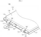
- the recessed groove 125 is shaped so that one side is opened to the outside, thereby reducing the case that the exposing portion 123 interferes with another object.
- it is easier to allow a welding tool to contact the lead connection plate 130 during a welding process or to set a target to which heat is applied by laser irradiation or the like at a predetermined distance.
- the electrically insulating material may be a polymer compound with a low electrical conductivity.
- the PCM insulation pad 140 may be made of a polymeric resin, silicone, rubber, or the like.
- the PCM insulation pad 140 may be formed by curing a hot-melt type polymer resin.
- the hot-melt type resin may be a hot-melt resin.
- the hot-melt resin is a solvent-free resin and may be a thermoplastic resin that is solid at normal temperature but is melted at a melting point or higher when heated and is solidified by cooling to form an adhesive.
- the PCM insulation pad 140 may be located at the other surface of the printed circuit board 121 on which the elements 127 and the parts 128 are mounted. That is, the PCM insulation pad 140 may be formed by mounting the elements 127 and the parts 128 on the other surface of the printed circuit board 121, applying a molten high-temperature resin to the upper surface, and then cooling the applied resin to be cured.
- the PCM insulation pad 140 may stably protect the elements 127 and the parts 128 mounted to the printed circuit board 121. Accordingly, in the present disclosure, it is possible to effectively prevent the elements 127 and the parts 128 of the printed circuit board 121 from being damaged or deviated due to an external impact.
- the PCM insulation pad 140 may be entirely formed of a transparent material so that the other surface of the printed circuit board 121 is observed.
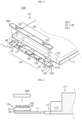
- FIG. 7 is a side view schematically showing that the protection circuit module of the pouch-type secondary battery pack according to an embodiment of the present disclosure is placed on the terrace portion.
- the PCM insulation pad 140 may be interposed between the other surface of the printed circuit board 121 and the terrace portion 117S.
- the PCM insulation pad 140 is interposed between the terrace portion 117S and the printed circuit board 121, it is possible to prevent the protection circuit module 120 and the battery cell 110 from being short-circuited or broken-down unintentionally.
- an insulating tape is separately attached to the terrace portion 117S to prevent a short circuit between the protection circuit module 120 and the battery cell 110.
- the PCM insulation pad 140 may electrically insulate the protection circuit module 120 and the battery cell 110 without attaching such an insulating tape.
- one surface of the PCM insulation pad 140 contacting the printed circuit board 121 may be formed along an outer surface of the elements 127 and the parts 128 of the printed circuit board 121.
- FIG. 8 is a partial perspective view schematically showing some components of a pouch-type secondary battery pack according to another embodiment of the present disclosure.
- a PCM insulation pad 140B according to another embodiment has a communicating portion 143 formed to communicate with the exposing portion 123 so that a portion of the lead connection plate 130 is exposed to the outside.
- the communicating portion 143 may be a communication hole 144 communicating with the perforation hole 124 and perforated from one surface to the other surface of the PCM insulation pad 140B.
- the communicating portion 143 may be a communication hole 144 communicating with the perforation hole 124 and perforated from one surface to the other surface of the PCM insulation pad 140B.
- two communication holes 144 may be formed to communicate with the perforation hole 124 formed in the printed circuit board 121, and the communication holes 144 may be formed at both sides of the printed circuit board 121 based on the center thereof.
- the communicating portion 143 may be an inwardly concave groove 145.
- the inwardly concave groove 145 may communicate with the recessed groove 125 and be inwardly recessed from the outer circumference of the PCM insulation pad 140A.
- two inwardly concave grooves 145 may be formed to communicate with two recessed grooves 125 formed at the printed circuit board 121A, and the inwardly concave grooves 145 may be formed at both sides of the printed circuit board 121A based on the center thereof.
- the PCM insulation pad 140 may be fixed to the other surface of the printed circuit board 121A by the fixing groove 147 so that the PCM insulation pad 140 is not easily deviated due to an external impact. Accordingly, the durability of the product according to the present disclosure may be effectively improved.
- a fixing hole 148B may be formed by digging one surface of the printed circuit board 121B to a predetermined depth D. Also, a portion of the PCM insulation pad 140A may be embedded in the inner space of the fixing hole 148B.
- FIG. 11 is a partial plane view schematically showing the protection circuit module 120E of the pouch-type secondary battery pack according to another embodiment of the present disclosure.
- the inclined portion 129 may be formed at a location on the other surface of the printed circuit board 121 corresponding to a location where another printed circuit board 150 is connected and coupled to one surface of the printed circuit board 121E.
- the inclined portion 129 may allow the applied molten resin to flow down along the inclined portion 129 and to be applied to one portion E of another printed circuit board 150.
- the melted resin is formed as portion of the PCM insulation pad 140E on another printed circuit board 150 along the inclined portion 129 of the present disclosure, it is possible to effectively prevent another printed circuit board 150 from being deviated from the printed circuit board 121E due to an external impact.
- the present disclosure relates to a pouch-type secondary battery pack.
- the present disclosure is available for industries associated with electric devices or vehicles including the pouch-type secondary battery pack.
Landscapes
- Chemical & Material Sciences (AREA)
- Chemical Kinetics & Catalysis (AREA)
- Electrochemistry (AREA)
- General Chemical & Material Sciences (AREA)
- Engineering & Computer Science (AREA)
- Microelectronics & Electronic Packaging (AREA)
- Manufacturing & Machinery (AREA)
- Power Engineering (AREA)
- Battery Mounting, Suspending (AREA)
Claims (11)
- Beuteltyp-Sekundärbatteriepack, umfassend:eine Batteriezelle (110), in welcher eine Elektrodenanordnung zusammen mit einem Elektrolyten in einem Beuteläußeren (115) abgedichtet ist, wobei die Batteriezelle eine Elektrodenleitung (111, 112) aufweist, welche an einer Seite davon gebildet ist; undein Schutzschaltungsmodul (120), welches eine Leiterplatte (121) mit einer daran gebildeten Schutzschaltung und eine Leitungsverbindungsplatte (130) aufweist, welche an einer Fläche der Leiterplatte (121) gebildet ist, so dass die Leiterplatte (121) elektrisch mit der Elektrodenleitung (111, 112) der Batteriezelle (110) verbunden ist, wobei das Schutzschaltungsmodul (120) einen freilegenden Abschnitt (123) aufweist, welcher an der anderen Fläche der Leiterplatte (121) gebildet ist, um wenigstens einen Abschnitt der Leitungsverbindungsplatte (130) freizulegen,wobei der freilegende Abschnitt (123) ein Perforationsloch (124), welches von einer Fläche zu der anderen Fläche der Leiterplatte (121) perforiert ist, oder eine ausgesparte Nut (125) ist, welche von einem Außenumfang der Leiterplatte (121) nach innen ausgespart ist,das Schutzschaltungsmodul (120) ferner ein Schutzschaltungsmodul- (PCM) - Isolierpad (140) umfasst, welches aus einem elektrisch isolierenden Material hergestellt ist und an der anderen Fläche der Leiterplatte (121) angeordnet ist, unddas PCM-Isolierpad (140) einen Verbindungsabschnitt (143) aufweist, welcher gebildet ist, um mit dem freilegenden Abschnitt (123) in Verbindung zu stehen, so dass ein Abschnitt der Leitungsverbindungsplatte (130) zu dem Äußeren freigelegt ist.
- Beuteltyp-Sekundärbatteriepack nach Anspruch 1,wobei die Leitungsverbindungsplatte (130) mit einer einzelnen flachen Lage gebildet ist undwobei die Leitungsverbindungsplatte (130) eine Fläche, von welcher wenigstens ein Abschnitt an eine Fläche der Leiterplatte (121) gebunden ist, und die andere Fläche aufweist, von welcher wenigstens ein Abschnitt an die Elektrodenleitung (111, 112) gebunden ist.
- Beuteltyp-Sekundärbatteriepack nach Anspruch 1,wobei das Beuteläußere (115) einen Aufnahmeabschnitt, in welchem die Elektrodenanordnung und der Elektrolyt aufgenommen sind, und einen Dichtabschnitt aufweist, welcher um den Aufnahmeabschnitt herum gebildet ist, undwobei das Schutzschaltungsmodul (120) an einem Terrassenabschnitt (117S) platziert ist, so dass die andere Fläche des PCM-Isolierpads (140) eine obere Fläche des Terrassenabschnitts (117S) des Dichtabschnitts kontaktiert, an welchem die Elektrodenleitung (111, 112) vorsteht.
- Beuteltyp-Sekundärbatteriepack nach Anspruch 1,
wobei der Verbindungsabschnitt (143) ein Verbindungsloch (144), welches mit dem Perforationsloch (124) in Verbindung steht und von einer Fläche zu der anderen Fläche des PCM-Isolierpads (140) perforiert ist, oder eine nach innen konkave Nut ist, welche mit der ausgesparten Nut (125) in Verbindung steht und an einem Außenumfang des PCM-Isolierpads (140) nach innen ausgespart ist. - Beuteltyp-Sekundärbatteriepack nach Anspruch 1,
wobei die Leiterplatte (121) einen eingebetteten Abschnitt (146) aufweist, in welchem ein Abschnitt des PCM-Isolierpads (140) eingebettet ist. - Beuteltyp-Sekundärbatteriepack nach Anspruch 5,
wobei der eingebettete Abschnitt (146) wenigstens eines aus einer Fixierungsnut (147), welche durch ein Einkerben eines Abschnitts des Außenumfangs der Leiterplatte (121) nach innen gebildet ist, und einem Fixierungsloch (148) ist, welches von der anderen Fläche der Leiterplatte (121) nach innen bis zu einer vorbestimmten Tiefe ausgespart ist. - Beuteltyp-Sekundärbatteriepack nach Anspruch 6,
wobei das Fixierungsloch (148) an beiden Seiten der Leiterplatte (121) gebildet ist, basierend auf einer Mitte davon. - Beuteltyp-Sekundärbatteriepack nach Anspruch 1,
wobei das PCM-Isolierpad (140) ein gehärtetes Heißschmelzharz ist, welches an der anderen Fläche der Leiterplatte (121) gebildet ist. - Beuteltyp-Sekundärbatteriepack nach Anspruch 1,
wobei wenigstens ein Abschnitt des PCM-Isolierpads (140) von einer Fläche zu der anderen Fläche davon aus einem transparenten Material hergestellt ist. - Beuteltyp-Sekundärbatteriepack nach Anspruch 1,
wobei das Schutzschaltungsmodul (120) ferner eine weitere Leiterplatte (150) umfasst, welche mit einem externen Eingangs-/Ausgangsanschluss verbunden und gekoppelt ist, welcher an der Leiterplatte (121) gebildet ist, und ein geneigter Abschnitt (129) an einer Stelle der anderen Fläche der Leiterplatte (121) gebildet ist, welche einer Stelle entspricht, an welcher die weitere Leiterplatte mit einer Fläche der Leiterplatte (121) verbunden und gekoppelt ist. - Beuteltyp-Sekundärbatteriepack, umfassend:eine Batteriezelle, in welcher eine Elektrodenanordnung zusammen mit einem Elektrolyten in einem Beuteläußeren abgedichtet ist, wobei die Batteriezelle eine Elektrodenleitung aufweist, welche an einer Seite davon gebildet ist; undein Schutzschaltungsmodul (120), welches eine Leiterplatte (121) mit einer daran gebildeten Schutzschaltung, eine Leitungsverbindungsplatte (130), welche an einer Fläche der Leiterplatte (121) gebildet ist, so dass die Leiterplatte elektrisch mit der Elektrodenleitung (111, 112) der Batteriezelle verbunden ist, und ein aus einem gehärteten Harz hergestelltes PCM-Isolierpad (140) aufweist, welches an der anderen Fläche der Leiterplatte (121) gebildet ist,wobei ein freilegender Abschnitt (123) an der anderen Fläche der Leiterplatte (121) gebildet ist, um wenigstens einen Abschnitt der Leitungsverbindungsplatte (130) freizulegen,wobei der freilegende Abschnitt (123) ein Perforationsloch (124), welches von einer Fläche zu der anderen Fläche der Leiterplatte (121) perforiert ist, oder eine ausgesparte Nut (125) ist, welche von einem Außenumfang der Leiterplatte (121) nach innen ausgespart ist,das PCM-Isolierpad (140) aus einem elektrisch isolierenden Material hergestellt ist unddas PCM-Isolierpad (140) einen Verbindungsabschnitt (143) aufweist, welcher gebildet ist, um mit dem freilegenden Abschnitt (123) in Verbindung zu stehen, so dass ein Abschnitt der Leitungsverbindungsplatte (130) zu dem Äußeren freigelegt ist.
Applications Claiming Priority (2)
| Application Number | Priority Date | Filing Date | Title |
|---|---|---|---|
| KR1020170126531A KR102168675B1 (ko) | 2017-09-28 | 2017-09-28 | 보호회로모듈을 구비한 파우치형 이차전지 팩 |
| PCT/KR2018/011333 WO2019066441A1 (ko) | 2017-09-28 | 2018-09-21 | 보호회로모듈을 구비한 파우치형 이차전지 팩 |
Publications (3)
| Publication Number | Publication Date |
|---|---|
| EP3573167A1 EP3573167A1 (de) | 2019-11-27 |
| EP3573167A4 EP3573167A4 (de) | 2020-04-01 |
| EP3573167B1 true EP3573167B1 (de) | 2025-07-02 |
Family
ID=65902623
Family Applications (1)
| Application Number | Title | Priority Date | Filing Date |
|---|---|---|---|
| EP18860026.6A Active EP3573167B1 (de) | 2017-09-28 | 2018-09-21 | Pouch-akkumulator mit schutzschaltungsmodul |
Country Status (8)
| Country | Link |
|---|---|
| US (1) | US11355788B2 (de) |
| EP (1) | EP3573167B1 (de) |
| JP (1) | JP6743312B2 (de) |
| KR (1) | KR102168675B1 (de) |
| CN (1) | CN110140254B (de) |
| ES (1) | ES3035909T3 (de) |
| HU (1) | HUE072718T2 (de) |
| WO (1) | WO2019066441A1 (de) |
Families Citing this family (14)
| Publication number | Priority date | Publication date | Assignee | Title |
|---|---|---|---|---|
| JP1667617S (de) * | 2019-07-05 | 2020-09-07 | ||
| JP1667633S (de) * | 2019-07-05 | 2020-09-07 | ||
| JP1667632S (de) * | 2019-07-05 | 2020-09-07 | ||
| JP1667618S (de) * | 2019-07-05 | 2020-09-07 | ||
| KR102128868B1 (ko) * | 2019-07-11 | 2020-07-01 | 주식회사 아이티엠반도체 | 배터리 보호회로 패키지 및 그 제조방법 |
| CN113314806B (zh) * | 2020-02-07 | 2023-05-16 | 北京小米移动软件有限公司 | 复合电池和电子设备 |
| CN114747070B (zh) * | 2020-06-30 | 2024-03-19 | 东莞新能德科技有限公司 | 电池、电池组件、电池组及电子装置 |
| EP3863107A1 (de) * | 2020-08-19 | 2021-08-11 | Beijing Xiaomi Mobile Software Co., Ltd. | Verbundbatterie und elektronische vorrichtung |
| KR20220029022A (ko) * | 2020-09-01 | 2022-03-08 | 삼성전자주식회사 | 배터리 및 그를 포함하는 전자 장치 |
| PL4184678T3 (pl) * | 2020-11-10 | 2026-01-26 | Lg Energy Solution, Ltd. | Pakiet akumulatorowy oraz urządzenie elektroniczne zawierające taki pakiet |
| KR102852053B1 (ko) * | 2021-01-27 | 2025-08-28 | 주식회사 엘지에너지솔루션 | 보호회로부 및 리드부와 보호회로부의 접합방법 |
| CN120303809A (zh) * | 2022-12-14 | 2025-07-11 | 三星电子株式会社 | 电池结构和包括电池结构的电子装置 |
| WO2025225172A1 (ja) * | 2024-04-23 | 2025-10-30 | パナソニックIpマネジメント株式会社 | 電池パック |
| CN119890619B (zh) * | 2025-01-23 | 2026-02-10 | 东莞新能德科技有限公司 | 电池及终端装置 |
Family Cites Families (34)
| Publication number | Priority date | Publication date | Assignee | Title |
|---|---|---|---|---|
| KR100601519B1 (ko) * | 2004-06-22 | 2006-07-19 | 삼성에스디아이 주식회사 | 파우치형 리튬 폴리머 전지 및 그 제조 방법 |
| KR100624977B1 (ko) | 2004-09-22 | 2006-09-15 | 삼성에스디아이 주식회사 | 파우치형 리튬 이차 전지 |
| KR100686807B1 (ko) | 2005-03-25 | 2007-02-26 | 삼성에스디아이 주식회사 | 폴리머 배터리 팩 및 그 제조 방법 |
| KR100846956B1 (ko) * | 2006-11-21 | 2008-07-17 | 삼성에스디아이 주식회사 | 보호회로 모듈을 갖는 이차전지 |
| KR100947963B1 (ko) * | 2007-09-28 | 2010-03-15 | 삼성에스디아이 주식회사 | 이차 전지용 보호회로 기판과 이를 이용한 이차 전지 |
| KR100959872B1 (ko) | 2008-01-04 | 2010-05-27 | 삼성에스디아이 주식회사 | 보호회로기판, 배터리 팩 및 이의 제조 방법 |
| KR101036086B1 (ko) | 2008-12-05 | 2011-05-19 | 삼성에스디아이 주식회사 | 이차전지 |
| KR101122790B1 (ko) | 2009-12-28 | 2012-03-21 | 삼성에스디아이 주식회사 | 이차전지 |
| US20110236727A1 (en) | 2010-03-29 | 2011-09-29 | Young-Cheol Jang | Secondary battery pack |
| KR101211859B1 (ko) | 2010-11-11 | 2012-12-12 | 삼성에스디아이 주식회사 | 보호회로모듈 및 이를 구비하는 배터리 팩 |
| US9065085B2 (en) | 2011-04-19 | 2015-06-23 | Samsung Sdi Co., Ltd. | Battery pack |
| KR20130018477A (ko) * | 2011-08-09 | 2013-02-25 | 주식회사 엘지화학 | 신규한 구조의 이차전지 팩 |
| KR101885908B1 (ko) * | 2011-11-17 | 2018-08-07 | 삼성에스디아이 주식회사 | 이차전지 팩 |
| KR101905080B1 (ko) | 2011-12-09 | 2018-10-05 | 삼성에스디아이 주식회사 | 배터리 팩 |
| KR101907211B1 (ko) | 2012-01-03 | 2018-10-11 | 삼성에스디아이 주식회사 | 파우치형 배터리 |
| KR101432224B1 (ko) | 2012-02-07 | 2014-08-26 | 주식회사 엘지화학 | 신규한 구조의 내장형 이차전지 팩 |
| KR101365968B1 (ko) | 2012-02-07 | 2014-02-24 | 주식회사 엘지화학 | 신규한 구조의 전지셀 제조방법 |
| KR101441524B1 (ko) | 2012-02-07 | 2014-09-17 | 주식회사 엘지화학 | 신규한 구조의 이차전지 팩 |
| US20130280558A1 (en) * | 2012-04-19 | 2013-10-24 | Samsung Sdi Co., Ltd. | Rechargeable battery |
| US20130323536A1 (en) * | 2012-05-31 | 2013-12-05 | Samsung Sdi Co., Ltd. | Rechargeable battery pack |
| KR101972601B1 (ko) | 2012-11-23 | 2019-04-25 | 에스케이이노베이션 주식회사 | 파우치형 이차전지용 내장프레임 및 상기 내장프레임을 갖는 이차전지 |
| US20140178715A1 (en) * | 2012-12-21 | 2014-06-26 | Samsung Sdi Co., Ltd. | Battery pack |
| KR101671371B1 (ko) * | 2013-05-23 | 2016-11-01 | 주식회사 엘지화학 | 비돌출 구조의 커넥터를 포함하고 있는 이차전지 팩 |
| KR101490026B1 (ko) | 2013-05-31 | 2015-02-06 | 박용미 | 배터리 팩 및 그 생산방법 |
| KR20140145787A (ko) | 2013-06-14 | 2014-12-24 | 삼성에스디아이 주식회사 | 이차 전지 팩 |
| KR102030111B1 (ko) * | 2013-09-04 | 2019-10-08 | 삼성에스디아이 주식회사 | 배터리 팩 |
| KR101619925B1 (ko) | 2013-09-27 | 2016-05-12 | 주식회사 엘지화학 | 보호회로모듈 고정테이프를 포함하는 전지팩 |
| KR101684349B1 (ko) * | 2013-09-30 | 2016-12-08 | 주식회사 엘지화학 | 보호회로모듈 케이스를 포함하는 전지팩 |
| KR102161628B1 (ko) | 2014-03-14 | 2020-10-05 | 삼성에스디아이 주식회사 | 배터리 보호회로모듈 및 이를 구비하는 배터리팩 |
| KR101778671B1 (ko) | 2014-10-31 | 2017-09-14 | 주식회사 엘지화학 | 클래드가 제거된 이차전지 팩 |
| KR101799563B1 (ko) | 2015-02-27 | 2017-11-20 | 주식회사 엘지화학 | 전지팩용 레이저 용접 지그 |
| KR102434771B1 (ko) | 2015-08-28 | 2022-08-22 | 삼성에스디아이 주식회사 | 배터리 팩 |
| KR101850294B1 (ko) | 2016-05-09 | 2018-04-20 | 한상욱 | 푸시 앤 풀 올 타입 도어용 손잡이 장치 |
| CN206322747U (zh) * | 2016-11-23 | 2017-07-11 | 吉安市优特利科技有限公司 | 一种连体式低压注塑电池 |
-
2017
- 2017-09-28 KR KR1020170126531A patent/KR102168675B1/ko active Active
-
2018
- 2018-09-21 CN CN201880005809.XA patent/CN110140254B/zh active Active
- 2018-09-21 ES ES18860026T patent/ES3035909T3/es active Active
- 2018-09-21 EP EP18860026.6A patent/EP3573167B1/de active Active
- 2018-09-21 WO PCT/KR2018/011333 patent/WO2019066441A1/ko not_active Ceased
- 2018-09-21 US US16/473,506 patent/US11355788B2/en active Active
- 2018-09-21 HU HUE18860026A patent/HUE072718T2/hu unknown
- 2018-09-21 JP JP2019558324A patent/JP6743312B2/ja active Active
Also Published As
| Publication number | Publication date |
|---|---|
| KR102168675B1 (ko) | 2020-10-21 |
| HUE072718T2 (hu) | 2025-12-28 |
| WO2019066441A1 (ko) | 2019-04-04 |
| JP2020515022A (ja) | 2020-05-21 |
| CN110140254B (zh) | 2022-05-03 |
| US11355788B2 (en) | 2022-06-07 |
| CN110140254A (zh) | 2019-08-16 |
| EP3573167A4 (de) | 2020-04-01 |
| EP3573167A1 (de) | 2019-11-27 |
| US20200144677A1 (en) | 2020-05-07 |
| ES3035909T3 (en) | 2025-09-11 |
| KR20190036979A (ko) | 2019-04-05 |
| JP6743312B2 (ja) | 2020-08-19 |
Similar Documents
| Publication | Publication Date | Title |
|---|---|---|
| EP3573167B1 (de) | Pouch-akkumulator mit schutzschaltungsmodul | |
| US10601081B2 (en) | Battery pack | |
| CN101136458B (zh) | 电池组及其制造方法 | |
| JP5059731B2 (ja) | バッテリパック | |
| US8709622B2 (en) | Protective circuit board and battery pack using the same | |
| US7887948B2 (en) | Pack type battery | |
| EP2216841B1 (de) | Beutelartige Lithiumsekundärbatterie | |
| US8228033B2 (en) | Protective circuit board having groove and battery pack using the same | |
| JP4795316B2 (ja) | 二次電池 | |
| US8936860B2 (en) | Battery pack with reinforcing member | |
| US9356262B2 (en) | Battery pack | |
| EP2405507B1 (de) | Wiederaufladbare Batterie | |
| EP3686951B1 (de) | Sekundärbatteriesatz mit halter | |
| KR100646528B1 (ko) | 파우치형 이차 전지 및 이를 이용한 제조 방법 | |
| KR102179687B1 (ko) | 배터리 팩 및 이의 제조방법 | |
| KR20160123788A (ko) | 전지 팩 | |
| US8790820B2 (en) | Secondary battery and method of manufacturing the same | |
| KR102637306B1 (ko) | 배터리 팩 및 이의 제조방법 | |
| CN114902470B (zh) | 电池组、电子装置和车辆 | |
| KR101386168B1 (ko) | 충방전이 가능한 배터리 팩 | |
| KR102422515B1 (ko) | 배터리 팩 |
Legal Events
| Date | Code | Title | Description |
|---|---|---|---|
| STAA | Information on the status of an ep patent application or granted ep patent |
Free format text: STATUS: THE INTERNATIONAL PUBLICATION HAS BEEN MADE |
|
| PUAI | Public reference made under article 153(3) epc to a published international application that has entered the european phase |
Free format text: ORIGINAL CODE: 0009012 |
|
| STAA | Information on the status of an ep patent application or granted ep patent |
Free format text: STATUS: REQUEST FOR EXAMINATION WAS MADE |
|
| 17P | Request for examination filed |
Effective date: 20190820 |
|
| AK | Designated contracting states |
Kind code of ref document: A1 Designated state(s): AL AT BE BG CH CY CZ DE DK EE ES FI FR GB GR HR HU IE IS IT LI LT LU LV MC MK MT NL NO PL PT RO RS SE SI SK SM TR |
|
| AX | Request for extension of the european patent |
Extension state: BA ME |
|
| A4 | Supplementary search report drawn up and despatched |
Effective date: 20200227 |
|
| RIC1 | Information provided on ipc code assigned before grant |
Ipc: H01M 2/02 20060101ALI20200222BHEP Ipc: H01M 10/42 20060101AFI20200222BHEP Ipc: H01M 2/34 20060101ALI20200222BHEP Ipc: H01M 2/10 20060101ALI20200222BHEP |
|
| DAV | Request for validation of the european patent (deleted) | ||
| DAX | Request for extension of the european patent (deleted) | ||
| RAP1 | Party data changed (applicant data changed or rights of an application transferred) |
Owner name: LG ENERGY SOLUTION LTD. |
|
| STAA | Information on the status of an ep patent application or granted ep patent |
Free format text: STATUS: EXAMINATION IS IN PROGRESS |
|
| 17Q | First examination report despatched |
Effective date: 20220222 |
|
| RAP3 | Party data changed (applicant data changed or rights of an application transferred) |
Owner name: LG ENERGY SOLUTION, LTD. |
|
| REG | Reference to a national code |
Ref country code: DE Ref legal event code: R079 Free format text: PREVIOUS MAIN CLASS: H01M0010420000 Ipc: H01M0050557000 Ref document number: 602018083289 Country of ref document: DE |
|
| GRAP | Despatch of communication of intention to grant a patent |
Free format text: ORIGINAL CODE: EPIDOSNIGR1 |
|
| STAA | Information on the status of an ep patent application or granted ep patent |
Free format text: STATUS: GRANT OF PATENT IS INTENDED |
|
| RIC1 | Information provided on ipc code assigned before grant |
Ipc: H01M 10/42 20060101ALI20250305BHEP Ipc: H01M 50/593 20210101ALI20250305BHEP Ipc: H01M 50/588 20210101ALI20250305BHEP Ipc: H01M 50/574 20210101ALI20250305BHEP Ipc: H01M 50/55 20210101ALI20250305BHEP Ipc: H01M 50/284 20210101ALI20250305BHEP Ipc: H01M 50/202 20210101ALI20250305BHEP Ipc: H01M 50/105 20210101ALI20250305BHEP Ipc: H01M 50/557 20210101AFI20250305BHEP |
|
| INTG | Intention to grant announced |
Effective date: 20250325 |
|
| P01 | Opt-out of the competence of the unified patent court (upc) registered |
Free format text: CASE NUMBER: APP_16819/2025 Effective date: 20250407 |
|
| GRAS | Grant fee paid |
Free format text: ORIGINAL CODE: EPIDOSNIGR3 |
|
| GRAA | (expected) grant |
Free format text: ORIGINAL CODE: 0009210 |
|
| STAA | Information on the status of an ep patent application or granted ep patent |
Free format text: STATUS: THE PATENT HAS BEEN GRANTED |
|
| AK | Designated contracting states |
Kind code of ref document: B1 Designated state(s): AL AT BE BG CH CY CZ DE DK EE ES FI FR GB GR HR HU IE IS IT LI LT LU LV MC MK MT NL NO PL PT RO RS SE SI SK SM TR |
|
| REG | Reference to a national code |
Ref country code: GB Ref legal event code: FG4D |
|
| REG | Reference to a national code |
Ref country code: CH Ref legal event code: EP |
|
| REG | Reference to a national code |
Ref country code: DE Ref legal event code: R096 Ref document number: 602018083289 Country of ref document: DE |
|
| REG | Reference to a national code |
Ref country code: IE Ref legal event code: FG4D |
|
| REG | Reference to a national code |
Ref country code: ES Ref legal event code: FG2A Ref document number: 3035909 Country of ref document: ES Kind code of ref document: T3 Effective date: 20250911 |
|
| PGFP | Annual fee paid to national office [announced via postgrant information from national office to epo] |
Ref country code: DE Payment date: 20250820 Year of fee payment: 8 |
|
| PGFP | Annual fee paid to national office [announced via postgrant information from national office to epo] |
Ref country code: BE Payment date: 20250820 Year of fee payment: 8 Ref country code: HU Payment date: 20250929 Year of fee payment: 8 Ref country code: GB Payment date: 20250820 Year of fee payment: 8 |
|
| PGFP | Annual fee paid to national office [announced via postgrant information from national office to epo] |
Ref country code: FR Payment date: 20250821 Year of fee payment: 8 |
|
| REG | Reference to a national code |
Ref country code: NL Ref legal event code: MP Effective date: 20250702 |
|
| PG25 | Lapsed in a contracting state [announced via postgrant information from national office to epo] |
Ref country code: PT Free format text: LAPSE BECAUSE OF FAILURE TO SUBMIT A TRANSLATION OF THE DESCRIPTION OR TO PAY THE FEE WITHIN THE PRESCRIBED TIME-LIMIT Effective date: 20251103 |
|
| PG25 | Lapsed in a contracting state [announced via postgrant information from national office to epo] |
Ref country code: NL Free format text: LAPSE BECAUSE OF FAILURE TO SUBMIT A TRANSLATION OF THE DESCRIPTION OR TO PAY THE FEE WITHIN THE PRESCRIBED TIME-LIMIT Effective date: 20250702 |
|
| REG | Reference to a national code |
Ref country code: AT Ref legal event code: MK05 Ref document number: 1810346 Country of ref document: AT Kind code of ref document: T Effective date: 20250702 |
|
| REG | Reference to a national code |
Ref country code: HU Ref legal event code: AG4A Ref document number: E072718 Country of ref document: HU |
|
| PG25 | Lapsed in a contracting state [announced via postgrant information from national office to epo] |
Ref country code: IS Free format text: LAPSE BECAUSE OF FAILURE TO SUBMIT A TRANSLATION OF THE DESCRIPTION OR TO PAY THE FEE WITHIN THE PRESCRIBED TIME-LIMIT Effective date: 20251102 |
|
| PG25 | Lapsed in a contracting state [announced via postgrant information from national office to epo] |
Ref country code: NO Free format text: LAPSE BECAUSE OF FAILURE TO SUBMIT A TRANSLATION OF THE DESCRIPTION OR TO PAY THE FEE WITHIN THE PRESCRIBED TIME-LIMIT Effective date: 20251002 |
|
| REG | Reference to a national code |
Ref country code: LT Ref legal event code: MG9D |
|
| PG25 | Lapsed in a contracting state [announced via postgrant information from national office to epo] |
Ref country code: AT Free format text: LAPSE BECAUSE OF FAILURE TO SUBMIT A TRANSLATION OF THE DESCRIPTION OR TO PAY THE FEE WITHIN THE PRESCRIBED TIME-LIMIT Effective date: 20250702 |
|
| PG25 | Lapsed in a contracting state [announced via postgrant information from national office to epo] |
Ref country code: FI Free format text: LAPSE BECAUSE OF FAILURE TO SUBMIT A TRANSLATION OF THE DESCRIPTION OR TO PAY THE FEE WITHIN THE PRESCRIBED TIME-LIMIT Effective date: 20250702 |
|
| PG25 | Lapsed in a contracting state [announced via postgrant information from national office to epo] |
Ref country code: HR Free format text: LAPSE BECAUSE OF FAILURE TO SUBMIT A TRANSLATION OF THE DESCRIPTION OR TO PAY THE FEE WITHIN THE PRESCRIBED TIME-LIMIT Effective date: 20250702 |
|
| PG25 | Lapsed in a contracting state [announced via postgrant information from national office to epo] |
Ref country code: GR Free format text: LAPSE BECAUSE OF FAILURE TO SUBMIT A TRANSLATION OF THE DESCRIPTION OR TO PAY THE FEE WITHIN THE PRESCRIBED TIME-LIMIT Effective date: 20251003 |
|
| PG25 | Lapsed in a contracting state [announced via postgrant information from national office to epo] |
Ref country code: SE Free format text: LAPSE BECAUSE OF FAILURE TO SUBMIT A TRANSLATION OF THE DESCRIPTION OR TO PAY THE FEE WITHIN THE PRESCRIBED TIME-LIMIT Effective date: 20250702 Ref country code: CZ Free format text: LAPSE BECAUSE OF FAILURE TO SUBMIT A TRANSLATION OF THE DESCRIPTION OR TO PAY THE FEE WITHIN THE PRESCRIBED TIME-LIMIT Effective date: 20250702 |
|
| PG25 | Lapsed in a contracting state [announced via postgrant information from national office to epo] |
Ref country code: LV Free format text: LAPSE BECAUSE OF FAILURE TO SUBMIT A TRANSLATION OF THE DESCRIPTION OR TO PAY THE FEE WITHIN THE PRESCRIBED TIME-LIMIT Effective date: 20250702 |
|
| PG25 | Lapsed in a contracting state [announced via postgrant information from national office to epo] |
Ref country code: BG Free format text: LAPSE BECAUSE OF FAILURE TO SUBMIT A TRANSLATION OF THE DESCRIPTION OR TO PAY THE FEE WITHIN THE PRESCRIBED TIME-LIMIT Effective date: 20250702 Ref country code: PL Free format text: LAPSE BECAUSE OF FAILURE TO SUBMIT A TRANSLATION OF THE DESCRIPTION OR TO PAY THE FEE WITHIN THE PRESCRIBED TIME-LIMIT Effective date: 20250702 |
|
| PG25 | Lapsed in a contracting state [announced via postgrant information from national office to epo] |
Ref country code: RS Free format text: LAPSE BECAUSE OF FAILURE TO SUBMIT A TRANSLATION OF THE DESCRIPTION OR TO PAY THE FEE WITHIN THE PRESCRIBED TIME-LIMIT Effective date: 20251002 |
|
| PGFP | Annual fee paid to national office [announced via postgrant information from national office to epo] |
Ref country code: ES Payment date: 20251008 Year of fee payment: 8 |
|
| PG25 | Lapsed in a contracting state [announced via postgrant information from national office to epo] |
Ref country code: RO Free format text: LAPSE BECAUSE OF FAILURE TO SUBMIT A TRANSLATION OF THE DESCRIPTION OR TO PAY THE FEE WITHIN THE PRESCRIBED TIME-LIMIT Effective date: 20250702 |
|
| PG25 | Lapsed in a contracting state [announced via postgrant information from national office to epo] |
Ref country code: SM Free format text: LAPSE BECAUSE OF FAILURE TO SUBMIT A TRANSLATION OF THE DESCRIPTION OR TO PAY THE FEE WITHIN THE PRESCRIBED TIME-LIMIT Effective date: 20250702 |
|
| PG25 | Lapsed in a contracting state [announced via postgrant information from national office to epo] |
Ref country code: DK Free format text: LAPSE BECAUSE OF FAILURE TO SUBMIT A TRANSLATION OF THE DESCRIPTION OR TO PAY THE FEE WITHIN THE PRESCRIBED TIME-LIMIT Effective date: 20250702 |
|
| PG25 | Lapsed in a contracting state [announced via postgrant information from national office to epo] |
Ref country code: IT Free format text: LAPSE BECAUSE OF FAILURE TO SUBMIT A TRANSLATION OF THE DESCRIPTION OR TO PAY THE FEE WITHIN THE PRESCRIBED TIME-LIMIT Effective date: 20250702 |
|
| REG | Reference to a national code |
Ref country code: CH Ref legal event code: H13 Free format text: ST27 STATUS EVENT CODE: U-0-0-H10-H13 (AS PROVIDED BY THE NATIONAL OFFICE) Effective date: 20260425 |
|
| PG25 | Lapsed in a contracting state [announced via postgrant information from national office to epo] |
Ref country code: SK Free format text: LAPSE BECAUSE OF FAILURE TO SUBMIT A TRANSLATION OF THE DESCRIPTION OR TO PAY THE FEE WITHIN THE PRESCRIBED TIME-LIMIT Effective date: 20250702 Ref country code: EE Free format text: LAPSE BECAUSE OF FAILURE TO SUBMIT A TRANSLATION OF THE DESCRIPTION OR TO PAY THE FEE WITHIN THE PRESCRIBED TIME-LIMIT Effective date: 20250702 |