EP3572056B1 - Tragenlagerungseinrichtung - Google Patents
Tragenlagerungseinrichtung Download PDFInfo
- Publication number
- EP3572056B1 EP3572056B1 EP18174201.6A EP18174201A EP3572056B1 EP 3572056 B1 EP3572056 B1 EP 3572056B1 EP 18174201 A EP18174201 A EP 18174201A EP 3572056 B1 EP3572056 B1 EP 3572056B1
- Authority
- EP
- European Patent Office
- Prior art keywords
- frame
- middle frame
- support device
- stretcher
- intermediate frame
- Prior art date
- Legal status (The legal status is an assumption and is not a legal conclusion. Google has not performed a legal analysis and makes no representation as to the accuracy of the status listed.)
- Active
Links
Images


Classifications
-
- A—HUMAN NECESSITIES
- A61—MEDICAL OR VETERINARY SCIENCE; HYGIENE
- A61G—TRANSPORT, PERSONAL CONVEYANCES, OR ACCOMMODATION SPECIALLY ADAPTED FOR PATIENTS OR DISABLED PERSONS; OPERATING TABLES OR CHAIRS; CHAIRS FOR DENTISTRY; FUNERAL DEVICES
- A61G3/00—Ambulance aspects of vehicles; Vehicles with special provisions for transporting patients or disabled persons, or their personal conveyances, e.g. for facilitating access of, or for loading, wheelchairs
- A61G3/02—Loading or unloading personal conveyances; Facilitating access of patients or disabled persons to, or exit from, vehicles
- A61G3/0218—Loading or unloading stretchers
- A61G3/0263—Loading or unloading stretchers by moving the stretcher on an inclined path, e.g. sliding or rolling
-
- A—HUMAN NECESSITIES
- A61—MEDICAL OR VETERINARY SCIENCE; HYGIENE
- A61G—TRANSPORT, PERSONAL CONVEYANCES, OR ACCOMMODATION SPECIALLY ADAPTED FOR PATIENTS OR DISABLED PERSONS; OPERATING TABLES OR CHAIRS; CHAIRS FOR DENTISTRY; FUNERAL DEVICES
- A61G3/00—Ambulance aspects of vehicles; Vehicles with special provisions for transporting patients or disabled persons, or their personal conveyances, e.g. for facilitating access of, or for loading, wheelchairs
- A61G3/02—Loading or unloading personal conveyances; Facilitating access of patients or disabled persons to, or exit from, vehicles
- A61G3/0218—Loading or unloading stretchers
- A61G3/0272—Loading or unloading stretchers by support protruding from the vehicle
-
- A—HUMAN NECESSITIES
- A61—MEDICAL OR VETERINARY SCIENCE; HYGIENE
- A61G—TRANSPORT, PERSONAL CONVEYANCES, OR ACCOMMODATION SPECIALLY ADAPTED FOR PATIENTS OR DISABLED PERSONS; OPERATING TABLES OR CHAIRS; CHAIRS FOR DENTISTRY; FUNERAL DEVICES
- A61G3/00—Ambulance aspects of vehicles; Vehicles with special provisions for transporting patients or disabled persons, or their personal conveyances, e.g. for facilitating access of, or for loading, wheelchairs
- A61G3/02—Loading or unloading personal conveyances; Facilitating access of patients or disabled persons to, or exit from, vehicles
- A61G3/0218—Loading or unloading stretchers
- A61G3/029—Loading or unloading stretchers by powered support
Definitions
- the present invention relates to a stretcher mounting device for storing a patient stretcher in a vehicle and for moving the stretcher out of or into the vehicle, wherein the stretcher mounting device can be connected to the structure of the vehicle so that the stretcher mounting device is arranged within the cargo space of the vehicle .
- Such stretcher storage devices are used to move a stretcher with a patient out of the plane on which the wheels of an ambulance vehicle rest into the cargo space of the vehicle, the height to be overcome can be very large if the vehicle is all-terrain and a has great ground clearance. In such cases, it is also necessary that the stretcher mounting device is driven, since a movement by hand can hardly be performed by one person alone. In addition, it is necessary that the stretcher mounting device manages the movement of the stretcher from the reception to the loading space in the shortest possible time, since there is often very little time available.
- Such a stretcher storage device is for example from DE 20 2015 008 857 U1 known.
- This device has an underframe which can be mounted on the floor of the loading space of a vehicle and to which a lower frame and an upper frame are attached, the lower frame with the upper frame telescopically guided therein being moved beyond a loading end of the lower frame and pivoted downward can.
- the upper frame is then extended telescopically out of the lower frame to an end position.
- a stretcher can be attached to the upper frame, and the upper frame is then pulled back into the lower frame.
- the subframe is swiveled back into the horizontal position and pulled back onto the subframe.
- the stretcher storage device has the problem that, due to the telescopic movement of the upper frame with respect to the lower frame, a great deal of space is required behind the vehicle during loading and unloading, especially when the vehicle has a large ground clearance and a large difference in height has to be overcome with the stretcher storage device This is disadvantageous because this space is often not available.
- the object of the present invention is to provide a stretcher mounting device for moving a patient stretcher into the cargo space of a vehicle, which is used to overcome the height difference between the plane in which the stretcher is located when it is picked up by the stretcher mounting device and the level in which the stretcher is positioned in the cargo area of the vehicle, requires as little space as possible outside the vehicle.
- a stretcher storage device with an underframe which is designed to be connected to the structure of a vehicle so that the stretcher storage device is arranged in a cargo space of the vehicle, with a subframe which is arranged on the underframe and is firmly connected to it wherein the subframe has a front end and a loading end and extends between them parallel to the floor surface, with an intermediate frame having first and second ends and which is slidably attached to the subframe so that it is between a retracted position in which the intermediate frame is positioned over the sub-frame so that the first end of the intermediate frame is positioned at the front end and the second end of the intermediate frame is positioned at the loading end, and an extended position in which the intermediate frame can be moved over the loading gsende also extends, and with an upper frame which has a flat loading surface and a first and a second end and which is slidably mounted on the intermediate frame such that it is relative to the intermediate frame between a retracted position in which the upper frame so above the
- the subframe has a preferably straight, first guide extending between the front end and the loading end, along which the first end of the intermediate frame is slidably guided, the loading end being a first support element has, on which is supported a facing to the bottom surface and extending between the first and second ends of the intermediate frame first support rail of the intermediate frame.
- the intermediate frame has a preferably rectilinear second guide extending between the first and second ends, along which the first end of the upper frame is slidably guided, the second end of the intermediate frame having a second support element on which a bottom surface and is supported between the first and second end of the upper frame extending second support rail of the upper frame.
- the course of the second support rail between the first end and the second end of the upper frame is such that the angle that the loading surface encloses with the intermediate frame is reduced when the upper frame is moved from the retracted position to the extended position.
- the subframe of the stretcher storage device according to the invention is designed such that it can be connected to the structure of the vehicle and the stretcher storage device is arranged in a cargo space of the vehicle. It is conceivable that the underframe is firmly connected to the floor of the cargo space. Alternatively, however, especially in armored vehicles, the floor area of which can be exposed to particular loads from mines, it is also possible to connect the underframe to the side walls or the ceiling area of the cargo space. In any case, however, the subframe is designed to be permanently coupled to the structure of the vehicle, that is to say to load-bearing parts of the body.
- the configuration according to the invention of the second support rail enables the following sequence of movement of the intermediate frame and the upper frame away from the lower frame.
- the intermediate frame is displaced relative to the subframe parallel to the displacement movement of the upper frame relative to the intermediate frame in such a way that the intermediate frame covers essentially the same distance per unit of time relative to the subframe as the upper frame relative to the intermediate frame, it comes to a Combination of a sliding movement of the upper frame out of the loading space and a tilting movement downwards.
- the second end of the intermediate frame is pushed out over the loading end of the subframe facing the vehicle opening, the angle of inclination of the intermediate frame increasing further and further. It takes this angle of inclination is even an angle greater than a critical angle of 16 °, for example.
- first support rails with which the intermediate frame is supported on the subframe have a first, possibly curved, course which causes the intermediate frame to tilt downwards when it is extended.
- the second support rails on the upper frame, with which the latter is in turn supported on the intermediate frame have a second, possibly also curved course, which is precisely opposite to the curved course of the first support rails.
- the inclination of the upper frame relative to the horizontal does not exceed a limit angle of 16 °, for example, currently defined by DIN EN 1789.
- the intermediate frame can take a much larger angle to the horizontal.
- this in turn means that the length of the area required by the stretcher mounting device according to the solution according to the invention to overcome a given height difference is significantly shorter than the length required by a stretcher mounting device according to the prior art , in which the upper frame is telescopically extended from the intermediate frame. Because in the prior art, the intermediate frame must not exceed a critical angle of 16 °, for example.
- the distance between the second guide and the first support rail, measured perpendicular to the second guide increases from the first end of the intermediate frame to the second end of the intermediate frame.
- the distance between the loading surface and the second support rail, measured perpendicular to the plane of the loading surface increases from the second end of the upper frame to the first end of the upper frame.
- first end of the intermediate frame should be pivotably supported on the lower frame and / or the first end of the upper frame is pivotably supported on the intermediate frame.
- the first guide preferably has straight first rails in which pivot bearings are guided at the first end of the intermediate frame and / or the second guide preferably has rectilinear second rails in which pivot bearings held at the first end of the upper frame are guided.
- a drive arrangement which is designed to close the intermediate frame with respect to the subframe between the retracted position and the extended position move and move the upper frame relative to the intermediate frame between the retracted and the extended position.
- control of the drive arrangement is designed such that the displacement movement between the subframe and the intermediate frame takes place parallel to the displacement movement between the intermediate frame and the upper frame, so that the intermediate frame takes the same distance per unit of time relative to the subframe covered like the upper frame relative to the intermediate frame.
- the drive device then ensures that the intermediate frame and the upper frame only assume those relative positions in which a predetermined limit angle for the inclination of the upper frame relative to the horizontal is not exceeded.
- the drive arrangement has a first engagement element on the subframe, which extends between the front end and the loading end, wherein a drive motor is supported on the intermediate frame, which drives a second engagement element in rotation, wherein the first and the second engagement element in such a way Are engaged so that a rotation of the second engagement element causes the sliding movement of the intermediate frame relative to the subframe. That way you can the relative movement between the subframe and the intermediate frame can be easily implemented by means of a motor attached to the intermediate frame.
- the first engagement element can be designed as a toothed belt and the second engagement element as a toothed wheel that engages with the toothed belt.
- the second engagement element is fastened to a drive shaft which is driven to rotate by the drive motor and which is rotatably supported on the intermediate frame.
- a holder is attached to the drive shaft so as to be pivotable about it, on which a first and a second deflection roller are mounted rotatably about axes of rotation, the axes of rotation extending parallel to the drive shaft and in a plane of rotation axes which runs parallel and offset to the drive shaft, the axes of rotation in the plane of the axis of rotation being laterally spaced from the projection of the drive shaft onto the plane of the axis of rotation, and the toothed belt being guided around the first deflection roller, the gearwheel and the second deflection roller.
- This structure enables the drive motor to be fixedly attached to the intermediate frame, although this is pivoted relative to the subframe and thus to the direction of travel of the toothed belt.
- a revolving drive belt can be held on a drive roller and at least one further roller on the intermediate frame, the drive roller being driven to rotate and a coupling piece connected to the upper frame being attached to the drive belt.
- the drive roller is more preferably attached to or on the drive shaft and is thus driven together with the gear. This enables only one motor to be required to effect the movement between the lower frame and the intermediate frame as well as that between the intermediate frame and the upper frame. This inevitably results in the parallel displacement movement described above.
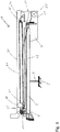
- the embodiment of a stretcher storage device 1 has a schematically illustrated underframe 3, which can be attached to the underside 5 of the underside 5 of the bottom surface of the loading space of a vehicle, which is not illustrated.
- the underframe 3 is designed in such a way that it can be permanently coupled to the structure of the vehicle and thus to load-bearing parts of the body.
- the stretcher mounting device 1 has a subframe 7 made up of two elements, which is arranged on the subframe 3 and is also firmly connected to it.
- the underframe 3 is designed in such a way that the inclination of the underframe 7 can be adjusted relative to the floor area of the cargo space. This makes it possible to change the inclination of a patient stretcher attached to the stretcher mounting device 1 when the stretcher mounting device 1 is in the retracted state.
- the sub-frame 7 has a front end 9 and a loading end 11 and extends between them parallel to the floor surface.
- the front end 9 is arranged away from the opening of the cargo space via which a patient stretcher is introduced into the cargo space, while the loading end 11 is positioned immediately adjacent thereto.
- a straight first guide extending between the front end 9 and the loading end 11 is provided on the subframe 7, this first guide being designed as straight first rails 13 in the exemplary embodiment described here, which on outwardly facing sides of the elements of the subframe 7 are attached so that the openings of the first rails 13 face outwards (see Figure 3 ).
- the stretcher mounting device has an intermediate frame 15, which in turn has a first end 17 and a second end 19.
- the intermediate frame 15 is attached above the subframe 7 and on the subframe 7 such that it can be displaced such that it can assume a retracted position relative to the subframe 7, as shown in FIG Figure 1 and in which the intermediate frame 15 is arranged above the subframe 7 such that the first end 17 of the intermediate frame 15 is arranged at the front end 9 and the second end 19 of the intermediate frame 15 is arranged at the loading end 11.
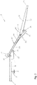
- the intermediate frame 15 can be moved relative to the sub-frame 7 in an extended position, as shown in FIG Figures 2 and 3 and in which the intermediate frame 15 extends beyond the loading end 11 of the lower frame 7.
- the first end 17 of the intermediate frame 15 is pivotally supported on the subframe 7 by 15 arms 21 are provided at the first end 17 of the intermediate frame 15, which extend over the first rails 13 and on which pivot bearings 23 are held are guided in the first rails 13 displaceably.
- the loading end 11 has a first support element 25 in the form of bearings on which first support rails 27 of the intermediate frame 15 that point towards the floor surface and extend between the first and second ends 17, 19 of the intermediate frame 15 are supported.
- first support rails 27 of the intermediate frame 15 that point towards the floor surface and extend between the first and second ends 17, 19 of the intermediate frame 15 are supported.
- second rails 29 which extend in a straight line between the first and second ends 17, 19 and which form a second guide.
- the stretcher support device 1 has an upper frame 31, which in turn is arranged above the intermediate frame 15 and which has a flat loading surface 33 on which a patient stretcher, not shown in the figures, can be releasably attached.
- the upper frame 31 has a first end 35 and a second end 37 and is attached to the intermediate frame 15 in a displaceable manner.
- the upper frame 31 can assume a retracted position relative to the intermediate frame 15, in which the upper frame 31 is arranged above the intermediate frame 15 that the first end 35 of the upper frame 31 is at the first end 17 of the intermediate frame 15 and the second end 37 of the Upper frame 31 are arranged at the second end 19 of the intermediate frame 15, as shown in FIG Figure 1 is shown.
- the upper frame 31 can be moved into an extended position in which the upper frame 31 extends beyond the second end 19 of the intermediate frame 15, like this in Figure 2 and 3 is shown.
- arms are provided on the upper frame 31 at the first end 35, which extend over the second rails 29 and to which pivot bearings are attached which are guided in the second rails 29.
- the first end 35 of the upper frame 31 can be pivoted and displaced on the intermediate frame 15.
- second support elements 39 are attached, which are designed as bearings and on which the second support rails 41 of the upper frame 31, pointing towards the bottom surface and extending between the first and second ends 35, 37 Support the upper frame 31.
- These second support rails 41 are in turn shown in FIG Figure 2 to recognize.
- the course of the second support rails 41 between the first end 35 and the second end 37 is such that the angle a that the loading surface 33 includes with the second guide or the second rails 29 and thus the plane of the intermediate frame 15 is reduced, when the upper frame 31 is moved from the retracted position to the extended position.
- the distance between the second rails 29 and the first support rails 27, measured perpendicular to the second rails 29, increases from the first end 17 of the intermediate frame 15 to the second end 19 of the intermediate frame 15.
- this embodiment increases the distance between the loading surface 33 and the second support rails 41, measured perpendicular to the plane of the loading surface 33, from the second end 37 of the upper frame 31 to the first end 35 of the upper frame 31.
- a drive arrangement is provided in the present embodiment, which is designed to move the intermediate frame 15 relative to the lower frame 7 between the retracted position and the extended position and to move the upper frame 31 relative to the intermediate frame 15 between the retracted and the extended position.
- the drive arrangement is designed such that the displacement movement between the lower frame 7 and the intermediate frame 15 takes place parallel to the displacement movement between the intermediate frame 15 and the upper frame 31 that the intermediate frame 15 covers the same distance per unit of time relative to the lower frame 7 as the upper frame 31 covers relative to the intermediate frame 15.
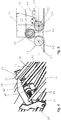
- the drive arrangement initially has a first engagement element in the form of a two-part toothed belt 43 which is fastened to the lower frame 7 and extends between its front end 9 and its loading end 11. Furthermore, a drive motor (not shown) is mounted on the intermediate frame 15, which drives a second engagement element in the form of a gear wheel 47 to rotate, the gear wheel 47 being attached to a drive shaft 49 which is spaced from the motor shaft of the drive motor and which is rotatably supported in the intermediate frame 15 (please refer Figure 4 ). The gear 47 is in engagement with the toothed belt 43, as shown in FIG Figure 5 which reproduces a sectional view perpendicular to the drive shaft 49.
- Two holders 51 on which a first and a second deflection roller 53, 55 are rotatably mounted about axes of rotation 57, are attached to the drive shaft 49 so as to be pivotable about this.
- the axes of rotation 57 extend parallel to the drive shaft 49 and in a plane of the axis of rotation 59 which runs parallel and offset to the drive shaft 49.
- the axes of rotation 57 in the axis of rotation plane 59 are arranged laterally spaced from the projection of the drive shaft 49 onto the axis of rotation plane 59.
- the toothed belt 43 is omega-shaped around the first deflection roller 53, the gear 47 and the second deflection roller 55 (see Figure 5 ). This structure has the advantage that the intermediate frame 15 with the drive motor attached to it can be pivoted relative to the subframe 7 with the toothed belt 43 attached to it, without the toothed belt 43 disengaging from the toothed wheel 47.
- a rotation of the gear wheel 47 causes the sliding movement of the intermediate frame 15 relative to the subframe 7, since the intermediate frame 15 is pulled along the toothed belt 43 when the gear wheel 47 rotates.
- a revolving drive belt 61 is guided on the intermediate frame 15 over a drive roller 63 and another roller 65, the drive roller 63 being fastened to the drive shaft 49 and thus driven in rotation by the drive motor together with the gear 47 (see Fig Figures 4 and 6th ).
- a coupling piece 67 is attached to the drive belt 61, which in turn is connected to the upper frame 31 via a holder 69, so that a movement of the drive belt 61 generated by the drive motor results in the displacement movement of the upper frame 31 (see also Figure 6 ).
- the stretcher mounting device 1 described above can be made from the in Figure 1 retracted position shown in Figure 2 and 3
- the extended position shown can be moved in that the drive motor is switched on so that the drive shaft 49 rotates.
- both the gear wheel 47 and the drive roller 63 rotate, so that parallel displacement movements of the intermediate frame 15 relative to the lower frame 7 and of the upper frame 31 relative to the intermediate frame 15 are effected by only one motor.
- additional means can be provided to rotate either the drive shaft 49 or the armature shaft of the drive motor by hand, so that the stretcher mounting device 1 can also be driven by hand and moved from the retracted to the extended position and vice versa .
- This compensation of the tilting movement of the intermediate frame 15 downwards by a tilting movement of the upper frame 31 relative to the intermediate frame 15 upwards is achieved in the exemplary embodiment by designing the first and second support rails 27, 41 on the intermediate frame 15 and upper frame 31 in the form of a "double curve geometry" .
- first support rails 27, with which the intermediate frame 15 is supported on the subframe 7 have a first, possibly curved, course.
- the second support rails 41 on the upper frame 31, with which it is supported on the intermediate frame 15 have a second, possibly also curved, course which is precisely opposite to the curved course of the first support rails 27.
- the intermediate frame 15 assumes a greater angle of inclination than the critical angle during the movement, the total length of the stretcher support device 1 is in the extended position (see FIG Figure 5 ) but much shorter than when the inclination of the intermediate frame 15 should not exceed the critical angle.
Landscapes
- Health & Medical Sciences (AREA)
- Public Health (AREA)
- Life Sciences & Earth Sciences (AREA)
- Animal Behavior & Ethology (AREA)
- General Health & Medical Sciences (AREA)
- Veterinary Medicine (AREA)
- Invalid Beds And Related Equipment (AREA)
- Handcart (AREA)
Priority Applications (3)
| Application Number | Priority Date | Filing Date | Title |
|---|---|---|---|
| EP18174201.6A EP3572056B1 (de) | 2018-05-24 | 2018-05-24 | Tragenlagerungseinrichtung |
| PL18174201T PL3572056T3 (pl) | 2018-05-24 | 2018-05-24 | Układ umieszczania noszy |
| ES18174201T ES2865430T3 (es) | 2018-05-24 | 2018-05-24 | Dispositivo de soporte de camilla |
Applications Claiming Priority (1)
| Application Number | Priority Date | Filing Date | Title |
|---|---|---|---|
| EP18174201.6A EP3572056B1 (de) | 2018-05-24 | 2018-05-24 | Tragenlagerungseinrichtung |
Publications (2)
| Publication Number | Publication Date |
|---|---|
| EP3572056A1 EP3572056A1 (de) | 2019-11-27 |
| EP3572056B1 true EP3572056B1 (de) | 2020-12-16 |
Family
ID=62567236
Family Applications (1)
| Application Number | Title | Priority Date | Filing Date |
|---|---|---|---|
| EP18174201.6A Active EP3572056B1 (de) | 2018-05-24 | 2018-05-24 | Tragenlagerungseinrichtung |
Country Status (3)
| Country | Link |
|---|---|
| EP (1) | EP3572056B1 (pl) |
| ES (1) | ES2865430T3 (pl) |
| PL (1) | PL3572056T3 (pl) |
Cited By (1)
| Publication number | Priority date | Publication date | Assignee | Title |
|---|---|---|---|---|
| IT202300019812A1 (it) * | 2023-09-26 | 2025-03-26 | Usai Chiara Francesca Laura | Sistema per carico e scarico nel portabagagli dell'autoveicolo del propulsore elettrico anteriore per carrozzina manuale ad autospinta |
Family Cites Families (4)
| Publication number | Priority date | Publication date | Assignee | Title |
|---|---|---|---|---|
| DE202009015121U1 (de) * | 2009-11-06 | 2010-01-21 | System Strobel Gmbh & Co. Kg | Vorrichtung zur Aufnahme einer Trage |
| CN103002853B (zh) * | 2010-02-22 | 2015-11-25 | Am通用有限责任公司 | 加载装置 |
| DE102010012065A1 (de) * | 2010-03-19 | 2011-09-22 | Eads Deutschland Gmbh | Tragenmodul |
| DE102015002448B4 (de) * | 2015-02-26 | 2018-05-30 | Airbus Defence and Space GmbH | Tragenverladesystem und Krankentransportwagen |
-
2018
- 2018-05-24 EP EP18174201.6A patent/EP3572056B1/de active Active
- 2018-05-24 ES ES18174201T patent/ES2865430T3/es active Active
- 2018-05-24 PL PL18174201T patent/PL3572056T3/pl unknown
Non-Patent Citations (1)
| Title |
|---|
| None * |
Cited By (1)
| Publication number | Priority date | Publication date | Assignee | Title |
|---|---|---|---|---|
| IT202300019812A1 (it) * | 2023-09-26 | 2025-03-26 | Usai Chiara Francesca Laura | Sistema per carico e scarico nel portabagagli dell'autoveicolo del propulsore elettrico anteriore per carrozzina manuale ad autospinta |
Also Published As
| Publication number | Publication date |
|---|---|
| ES2865430T3 (es) | 2021-10-15 |
| EP3572056A1 (de) | 2019-11-27 |
| PL3572056T3 (pl) | 2021-08-16 |
Similar Documents
| Publication | Publication Date | Title |
|---|---|---|
| EP1587701B1 (de) | Schwenkschiebetür für fahrzeuge | |
| AT405155B (de) | Schwenkschiebetür für fahrzeuge | |
| EP0395847A2 (de) | Antriebseinrichtung für ein motorisch angetriebenes Klappverdeck | |
| DE3916976C2 (pl) | ||
| DE10145476B4 (de) | Freies Gelenkarmsystem füe eine präzise Kontrolle | |
| DE19828464C1 (de) | Vorrichtung zur Betätigung eines Hebe-Schiebedaches | |
| DE3027835A1 (de) | Wahlweise kipp- oder parallel abstellbarer fluegel eines fensters, einer tuer o.dgl. | |
| DE69201691T2 (de) | Mobiles Röntgengerät. | |
| DE102015207736B4 (de) | Mobiles C-Bogen-Röntgengerät | |
| EP3572056B1 (de) | Tragenlagerungseinrichtung | |
| DE10250905B4 (de) | Verstelleinrichtung für ein Lenkrad eines Flurförderzeugs | |
| DE1104713B (de) | Vorrichtung zum Neigen einer Stuetze | |
| DE2633683C2 (de) | Transportfahrzeug für Fertiggaragen und dergleichen | |
| DE19737678A1 (de) | Fahrzeug mit Rahmenabstützung | |
| DE2529556A1 (de) | Vorrichtung zur einstellung eines fahrzeugsitzes | |
| DE3431498C1 (de) | Hub- und Schwenkvorrichtung fuer den Austragsabschnitt einer rohrfoermigen Schuttrutsche | |
| DE202014105344U1 (de) | Universeller Manipulator | |
| DE102022113665B3 (de) | Fahrzeugkarosseriefördereinrichtung | |
| DE10065130B4 (de) | Windschild für Motorräder | |
| DE102019006403A1 (de) | Transportsystem sowie Verfahren zum Transportieren eines Kraftwagenrohbaus | |
| EP0788767A1 (de) | Röntgendiagnostikgerät | |
| EP3425152A1 (de) | Schwenkschiebetür | |
| EP0187388A2 (de) | Höhenverstellbares Abstützgerät, insbesondere Sattelaufliegerstütze | |
| DE102015008649A1 (de) | Fahrzeugsitz und Fahrzeug | |
| CH708120A2 (de) | Universeller Manipulator. |
Legal Events
| Date | Code | Title | Description |
|---|---|---|---|
| PUAI | Public reference made under article 153(3) epc to a published international application that has entered the european phase |
Free format text: ORIGINAL CODE: 0009012 |
|
| STAA | Information on the status of an ep patent application or granted ep patent |
Free format text: STATUS: THE APPLICATION HAS BEEN PUBLISHED |
|
| AK | Designated contracting states |
Kind code of ref document: A1 Designated state(s): AL AT BE BG CH CY CZ DE DK EE ES FI FR GB GR HR HU IE IS IT LI LT LU LV MC MK MT NL NO PL PT RO RS SE SI SK SM TR |
|
| AX | Request for extension of the european patent |
Extension state: BA ME |
|
| STAA | Information on the status of an ep patent application or granted ep patent |
Free format text: STATUS: REQUEST FOR EXAMINATION WAS MADE |
|
| 17P | Request for examination filed |
Effective date: 20200401 |
|
| RBV | Designated contracting states (corrected) |
Designated state(s): AL AT BE BG CH CY CZ DE DK EE ES FI FR GB GR HR HU IE IS IT LI LT LU LV MC MK MT NL NO PL PT RO RS SE SI SK SM TR |
|
| GRAP | Despatch of communication of intention to grant a patent |
Free format text: ORIGINAL CODE: EPIDOSNIGR1 |
|
| STAA | Information on the status of an ep patent application or granted ep patent |
Free format text: STATUS: GRANT OF PATENT IS INTENDED |
|
| INTG | Intention to grant announced |
Effective date: 20200629 |
|
| GRAS | Grant fee paid |
Free format text: ORIGINAL CODE: EPIDOSNIGR3 |
|
| GRAA | (expected) grant |
Free format text: ORIGINAL CODE: 0009210 |
|
| STAA | Information on the status of an ep patent application or granted ep patent |
Free format text: STATUS: THE PATENT HAS BEEN GRANTED |
|
| AK | Designated contracting states |
Kind code of ref document: B1 Designated state(s): AL AT BE BG CH CY CZ DE DK EE ES FI FR GB GR HR HU IE IS IT LI LT LU LV MC MK MT NL NO PL PT RO RS SE SI SK SM TR |
|
| REG | Reference to a national code |
Ref country code: GB Ref legal event code: FG4D Free format text: NOT ENGLISH |
|
| REG | Reference to a national code |
Ref country code: DE Ref legal event code: R096 Ref document number: 502018003298 Country of ref document: DE |
|
| REG | Reference to a national code |
Ref country code: IE Ref legal event code: FG4D Free format text: LANGUAGE OF EP DOCUMENT: GERMAN |
|
| REG | Reference to a national code |
Ref country code: AT Ref legal event code: REF Ref document number: 1344911 Country of ref document: AT Kind code of ref document: T Effective date: 20210115 |
|
| REG | Reference to a national code |
Ref country code: FI Ref legal event code: FGE |
|
| PG25 | Lapsed in a contracting state [announced via postgrant information from national office to epo] |
Ref country code: RS Free format text: LAPSE BECAUSE OF FAILURE TO SUBMIT A TRANSLATION OF THE DESCRIPTION OR TO PAY THE FEE WITHIN THE PRESCRIBED TIME-LIMIT Effective date: 20201216 Ref country code: NO Free format text: LAPSE BECAUSE OF FAILURE TO SUBMIT A TRANSLATION OF THE DESCRIPTION OR TO PAY THE FEE WITHIN THE PRESCRIBED TIME-LIMIT Effective date: 20210316 Ref country code: GR Free format text: LAPSE BECAUSE OF FAILURE TO SUBMIT A TRANSLATION OF THE DESCRIPTION OR TO PAY THE FEE WITHIN THE PRESCRIBED TIME-LIMIT Effective date: 20210317 |
|
| REG | Reference to a national code |
Ref country code: NL Ref legal event code: MP Effective date: 20201216 |
|
| PG25 | Lapsed in a contracting state [announced via postgrant information from national office to epo] |
Ref country code: BG Free format text: LAPSE BECAUSE OF FAILURE TO SUBMIT A TRANSLATION OF THE DESCRIPTION OR TO PAY THE FEE WITHIN THE PRESCRIBED TIME-LIMIT Effective date: 20210316 Ref country code: LV Free format text: LAPSE BECAUSE OF FAILURE TO SUBMIT A TRANSLATION OF THE DESCRIPTION OR TO PAY THE FEE WITHIN THE PRESCRIBED TIME-LIMIT Effective date: 20201216 Ref country code: SE Free format text: LAPSE BECAUSE OF FAILURE TO SUBMIT A TRANSLATION OF THE DESCRIPTION OR TO PAY THE FEE WITHIN THE PRESCRIBED TIME-LIMIT Effective date: 20201216 |
|
| PG25 | Lapsed in a contracting state [announced via postgrant information from national office to epo] |
Ref country code: NL Free format text: LAPSE BECAUSE OF FAILURE TO SUBMIT A TRANSLATION OF THE DESCRIPTION OR TO PAY THE FEE WITHIN THE PRESCRIBED TIME-LIMIT Effective date: 20201216 Ref country code: HR Free format text: LAPSE BECAUSE OF FAILURE TO SUBMIT A TRANSLATION OF THE DESCRIPTION OR TO PAY THE FEE WITHIN THE PRESCRIBED TIME-LIMIT Effective date: 20201216 |
|
| REG | Reference to a national code |
Ref country code: LT Ref legal event code: MG9D |
|
| PG25 | Lapsed in a contracting state [announced via postgrant information from national office to epo] |
Ref country code: SM Free format text: LAPSE BECAUSE OF FAILURE TO SUBMIT A TRANSLATION OF THE DESCRIPTION OR TO PAY THE FEE WITHIN THE PRESCRIBED TIME-LIMIT Effective date: 20201216 Ref country code: LT Free format text: LAPSE BECAUSE OF FAILURE TO SUBMIT A TRANSLATION OF THE DESCRIPTION OR TO PAY THE FEE WITHIN THE PRESCRIBED TIME-LIMIT Effective date: 20201216 Ref country code: SK Free format text: LAPSE BECAUSE OF FAILURE TO SUBMIT A TRANSLATION OF THE DESCRIPTION OR TO PAY THE FEE WITHIN THE PRESCRIBED TIME-LIMIT Effective date: 20201216 Ref country code: PT Free format text: LAPSE BECAUSE OF FAILURE TO SUBMIT A TRANSLATION OF THE DESCRIPTION OR TO PAY THE FEE WITHIN THE PRESCRIBED TIME-LIMIT Effective date: 20210416 Ref country code: RO Free format text: LAPSE BECAUSE OF FAILURE TO SUBMIT A TRANSLATION OF THE DESCRIPTION OR TO PAY THE FEE WITHIN THE PRESCRIBED TIME-LIMIT Effective date: 20201216 Ref country code: EE Free format text: LAPSE BECAUSE OF FAILURE TO SUBMIT A TRANSLATION OF THE DESCRIPTION OR TO PAY THE FEE WITHIN THE PRESCRIBED TIME-LIMIT Effective date: 20201216 |
|
| REG | Reference to a national code |
Ref country code: DE Ref legal event code: R097 Ref document number: 502018003298 Country of ref document: DE |
|
| PG25 | Lapsed in a contracting state [announced via postgrant information from national office to epo] |
Ref country code: IS Free format text: LAPSE BECAUSE OF FAILURE TO SUBMIT A TRANSLATION OF THE DESCRIPTION OR TO PAY THE FEE WITHIN THE PRESCRIBED TIME-LIMIT Effective date: 20210416 |
|
| REG | Reference to a national code |
Ref country code: ES Ref legal event code: FG2A Ref document number: 2865430 Country of ref document: ES Kind code of ref document: T3 Effective date: 20211015 |
|
| PLBE | No opposition filed within time limit |
Free format text: ORIGINAL CODE: 0009261 |
|
| STAA | Information on the status of an ep patent application or granted ep patent |
Free format text: STATUS: NO OPPOSITION FILED WITHIN TIME LIMIT |
|
| PG25 | Lapsed in a contracting state [announced via postgrant information from national office to epo] |
Ref country code: AL Free format text: LAPSE BECAUSE OF FAILURE TO SUBMIT A TRANSLATION OF THE DESCRIPTION OR TO PAY THE FEE WITHIN THE PRESCRIBED TIME-LIMIT Effective date: 20201216 |
|
| 26N | No opposition filed |
Effective date: 20210917 |
|
| PG25 | Lapsed in a contracting state [announced via postgrant information from national office to epo] |
Ref country code: DK Free format text: LAPSE BECAUSE OF FAILURE TO SUBMIT A TRANSLATION OF THE DESCRIPTION OR TO PAY THE FEE WITHIN THE PRESCRIBED TIME-LIMIT Effective date: 20201216 |
|
| REG | Reference to a national code |
Ref country code: CH Ref legal event code: PL |
|
| PG25 | Lapsed in a contracting state [announced via postgrant information from national office to epo] |
Ref country code: CH Free format text: LAPSE BECAUSE OF NON-PAYMENT OF DUE FEES Effective date: 20210531 Ref country code: MC Free format text: LAPSE BECAUSE OF FAILURE TO SUBMIT A TRANSLATION OF THE DESCRIPTION OR TO PAY THE FEE WITHIN THE PRESCRIBED TIME-LIMIT Effective date: 20201216 Ref country code: LU Free format text: LAPSE BECAUSE OF NON-PAYMENT OF DUE FEES Effective date: 20210524 Ref country code: LI Free format text: LAPSE BECAUSE OF NON-PAYMENT OF DUE FEES Effective date: 20210531 |
|
| REG | Reference to a national code |
Ref country code: BE Ref legal event code: MM Effective date: 20210531 |
|
| PG25 | Lapsed in a contracting state [announced via postgrant information from national office to epo] |
Ref country code: SI Free format text: LAPSE BECAUSE OF FAILURE TO SUBMIT A TRANSLATION OF THE DESCRIPTION OR TO PAY THE FEE WITHIN THE PRESCRIBED TIME-LIMIT Effective date: 20201216 |
|
| PG25 | Lapsed in a contracting state [announced via postgrant information from national office to epo] |
Ref country code: LI Free format text: LAPSE BECAUSE OF NON-PAYMENT OF DUE FEES Effective date: 20210531 Ref country code: IE Free format text: LAPSE BECAUSE OF NON-PAYMENT OF DUE FEES Effective date: 20210524 Ref country code: CH Free format text: LAPSE BECAUSE OF NON-PAYMENT OF DUE FEES Effective date: 20210531 |
|
| PGRI | Patent reinstated in contracting state [announced from national office to epo] |
Ref country code: LI Effective date: 20220110 Ref country code: CH Effective date: 20220110 |
|
| PG25 | Lapsed in a contracting state [announced via postgrant information from national office to epo] |
Ref country code: IS Free format text: LAPSE BECAUSE OF FAILURE TO SUBMIT A TRANSLATION OF THE DESCRIPTION OR TO PAY THE FEE WITHIN THE PRESCRIBED TIME-LIMIT Effective date: 20210416 |
|
| PG25 | Lapsed in a contracting state [announced via postgrant information from national office to epo] |
Ref country code: BE Free format text: LAPSE BECAUSE OF NON-PAYMENT OF DUE FEES Effective date: 20210531 |
|
| REG | Reference to a national code |
Ref country code: CH Ref legal event code: PL |
|
| PG25 | Lapsed in a contracting state [announced via postgrant information from national office to epo] |
Ref country code: LI Free format text: LAPSE BECAUSE OF NON-PAYMENT OF DUE FEES Effective date: 20220531 Ref country code: CH Free format text: LAPSE BECAUSE OF NON-PAYMENT OF DUE FEES Effective date: 20220531 |
|
| PGRI | Patent reinstated in contracting state [announced from national office to epo] |
Ref country code: LI Effective date: 20230106 Ref country code: CH Effective date: 20230106 |
|
| PG25 | Lapsed in a contracting state [announced via postgrant information from national office to epo] |
Ref country code: CY Free format text: LAPSE BECAUSE OF FAILURE TO SUBMIT A TRANSLATION OF THE DESCRIPTION OR TO PAY THE FEE WITHIN THE PRESCRIBED TIME-LIMIT Effective date: 20201216 |
|
| PG25 | Lapsed in a contracting state [announced via postgrant information from national office to epo] |
Ref country code: HU Free format text: LAPSE BECAUSE OF FAILURE TO SUBMIT A TRANSLATION OF THE DESCRIPTION OR TO PAY THE FEE WITHIN THE PRESCRIBED TIME-LIMIT; INVALID AB INITIO Effective date: 20180524 |
|
| REG | Reference to a national code |
Ref country code: DE Ref legal event code: R082 Ref document number: 502018003298 Country of ref document: DE Representative=s name: WEIDNER STERN JESCHKE PATENTANWAELTE PARTNERSC, DE |
|
| PG25 | Lapsed in a contracting state [announced via postgrant information from national office to epo] |
Ref country code: MK Free format text: LAPSE BECAUSE OF FAILURE TO SUBMIT A TRANSLATION OF THE DESCRIPTION OR TO PAY THE FEE WITHIN THE PRESCRIBED TIME-LIMIT Effective date: 20201216 |
|
| PG25 | Lapsed in a contracting state [announced via postgrant information from national office to epo] |
Ref country code: MT Free format text: LAPSE BECAUSE OF FAILURE TO SUBMIT A TRANSLATION OF THE DESCRIPTION OR TO PAY THE FEE WITHIN THE PRESCRIBED TIME-LIMIT Effective date: 20201216 |
|
| PGFP | Annual fee paid to national office [announced via postgrant information from national office to epo] |
Ref country code: FI Payment date: 20250520 Year of fee payment: 8 |
|
| PGFP | Annual fee paid to national office [announced via postgrant information from national office to epo] |
Ref country code: PL Payment date: 20250516 Year of fee payment: 8 Ref country code: DE Payment date: 20250428 Year of fee payment: 8 |
|
| PGFP | Annual fee paid to national office [announced via postgrant information from national office to epo] |
Ref country code: ES Payment date: 20250616 Year of fee payment: 8 Ref country code: GB Payment date: 20250522 Year of fee payment: 8 |
|
| PGFP | Annual fee paid to national office [announced via postgrant information from national office to epo] |
Ref country code: IT Payment date: 20250530 Year of fee payment: 8 |
|
| PGFP | Annual fee paid to national office [announced via postgrant information from national office to epo] |
Ref country code: FR Payment date: 20250521 Year of fee payment: 8 |
|
| PGFP | Annual fee paid to national office [announced via postgrant information from national office to epo] |
Ref country code: CH Payment date: 20250601 Year of fee payment: 8 |
|
| PGFP | Annual fee paid to national office [announced via postgrant information from national office to epo] |
Ref country code: AT Payment date: 20250519 Year of fee payment: 8 |
|
| PGFP | Annual fee paid to national office [announced via postgrant information from national office to epo] |
Ref country code: CZ Payment date: 20250509 Year of fee payment: 8 |
|
| PG25 | Lapsed in a contracting state [announced via postgrant information from national office to epo] |
Ref country code: TR Free format text: LAPSE BECAUSE OF FAILURE TO SUBMIT A TRANSLATION OF THE DESCRIPTION OR TO PAY THE FEE WITHIN THE PRESCRIBED TIME-LIMIT Effective date: 20201216 |