EP3572056B1 - Stretcher support device - Google Patents
Stretcher support device Download PDFInfo
- Publication number
- EP3572056B1 EP3572056B1 EP18174201.6A EP18174201A EP3572056B1 EP 3572056 B1 EP3572056 B1 EP 3572056B1 EP 18174201 A EP18174201 A EP 18174201A EP 3572056 B1 EP3572056 B1 EP 3572056B1
- Authority
- EP
- European Patent Office
- Prior art keywords
- frame
- middle frame
- support device
- stretcher
- intermediate frame
- Prior art date
- Legal status (The legal status is an assumption and is not a legal conclusion. Google has not performed a legal analysis and makes no representation as to the accuracy of the status listed.)
- Active
Links
Images


Classifications
-
- A—HUMAN NECESSITIES
- A61—MEDICAL OR VETERINARY SCIENCE; HYGIENE
- A61G—TRANSPORT, PERSONAL CONVEYANCES, OR ACCOMMODATION SPECIALLY ADAPTED FOR PATIENTS OR DISABLED PERSONS; OPERATING TABLES OR CHAIRS; CHAIRS FOR DENTISTRY; FUNERAL DEVICES
- A61G3/00—Ambulance aspects of vehicles; Vehicles with special provisions for transporting patients or disabled persons, or their personal conveyances, e.g. for facilitating access of, or for loading, wheelchairs
- A61G3/02—Loading or unloading personal conveyances; Facilitating access of patients or disabled persons to, or exit from, vehicles
- A61G3/0218—Loading or unloading stretchers
- A61G3/0263—Loading or unloading stretchers by moving the stretcher on an inclined path, e.g. sliding or rolling
-
- A—HUMAN NECESSITIES
- A61—MEDICAL OR VETERINARY SCIENCE; HYGIENE
- A61G—TRANSPORT, PERSONAL CONVEYANCES, OR ACCOMMODATION SPECIALLY ADAPTED FOR PATIENTS OR DISABLED PERSONS; OPERATING TABLES OR CHAIRS; CHAIRS FOR DENTISTRY; FUNERAL DEVICES
- A61G3/00—Ambulance aspects of vehicles; Vehicles with special provisions for transporting patients or disabled persons, or their personal conveyances, e.g. for facilitating access of, or for loading, wheelchairs
- A61G3/02—Loading or unloading personal conveyances; Facilitating access of patients or disabled persons to, or exit from, vehicles
- A61G3/0218—Loading or unloading stretchers
- A61G3/0272—Loading or unloading stretchers by support protruding from the vehicle
-
- A—HUMAN NECESSITIES
- A61—MEDICAL OR VETERINARY SCIENCE; HYGIENE
- A61G—TRANSPORT, PERSONAL CONVEYANCES, OR ACCOMMODATION SPECIALLY ADAPTED FOR PATIENTS OR DISABLED PERSONS; OPERATING TABLES OR CHAIRS; CHAIRS FOR DENTISTRY; FUNERAL DEVICES
- A61G3/00—Ambulance aspects of vehicles; Vehicles with special provisions for transporting patients or disabled persons, or their personal conveyances, e.g. for facilitating access of, or for loading, wheelchairs
- A61G3/02—Loading or unloading personal conveyances; Facilitating access of patients or disabled persons to, or exit from, vehicles
- A61G3/0218—Loading or unloading stretchers
- A61G3/029—Loading or unloading stretchers by powered support
Definitions
- the present invention relates to a stretcher mounting device for storing a patient stretcher in a vehicle and for moving the stretcher out of or into the vehicle, wherein the stretcher mounting device can be connected to the structure of the vehicle so that the stretcher mounting device is arranged within the cargo space of the vehicle .
- Such stretcher storage devices are used to move a stretcher with a patient out of the plane on which the wheels of an ambulance vehicle rest into the cargo space of the vehicle, the height to be overcome can be very large if the vehicle is all-terrain and a has great ground clearance. In such cases, it is also necessary that the stretcher mounting device is driven, since a movement by hand can hardly be performed by one person alone. In addition, it is necessary that the stretcher mounting device manages the movement of the stretcher from the reception to the loading space in the shortest possible time, since there is often very little time available.
- Such a stretcher storage device is for example from DE 20 2015 008 857 U1 known.
- This device has an underframe which can be mounted on the floor of the loading space of a vehicle and to which a lower frame and an upper frame are attached, the lower frame with the upper frame telescopically guided therein being moved beyond a loading end of the lower frame and pivoted downward can.
- the upper frame is then extended telescopically out of the lower frame to an end position.
- a stretcher can be attached to the upper frame, and the upper frame is then pulled back into the lower frame.
- the subframe is swiveled back into the horizontal position and pulled back onto the subframe.
- the stretcher storage device has the problem that, due to the telescopic movement of the upper frame with respect to the lower frame, a great deal of space is required behind the vehicle during loading and unloading, especially when the vehicle has a large ground clearance and a large difference in height has to be overcome with the stretcher storage device This is disadvantageous because this space is often not available.
- the object of the present invention is to provide a stretcher mounting device for moving a patient stretcher into the cargo space of a vehicle, which is used to overcome the height difference between the plane in which the stretcher is located when it is picked up by the stretcher mounting device and the level in which the stretcher is positioned in the cargo area of the vehicle, requires as little space as possible outside the vehicle.
- a stretcher storage device with an underframe which is designed to be connected to the structure of a vehicle so that the stretcher storage device is arranged in a cargo space of the vehicle, with a subframe which is arranged on the underframe and is firmly connected to it wherein the subframe has a front end and a loading end and extends between them parallel to the floor surface, with an intermediate frame having first and second ends and which is slidably attached to the subframe so that it is between a retracted position in which the intermediate frame is positioned over the sub-frame so that the first end of the intermediate frame is positioned at the front end and the second end of the intermediate frame is positioned at the loading end, and an extended position in which the intermediate frame can be moved over the loading gsende also extends, and with an upper frame which has a flat loading surface and a first and a second end and which is slidably mounted on the intermediate frame such that it is relative to the intermediate frame between a retracted position in which the upper frame so above the
- the subframe has a preferably straight, first guide extending between the front end and the loading end, along which the first end of the intermediate frame is slidably guided, the loading end being a first support element has, on which is supported a facing to the bottom surface and extending between the first and second ends of the intermediate frame first support rail of the intermediate frame.
- the intermediate frame has a preferably rectilinear second guide extending between the first and second ends, along which the first end of the upper frame is slidably guided, the second end of the intermediate frame having a second support element on which a bottom surface and is supported between the first and second end of the upper frame extending second support rail of the upper frame.
- the course of the second support rail between the first end and the second end of the upper frame is such that the angle that the loading surface encloses with the intermediate frame is reduced when the upper frame is moved from the retracted position to the extended position.
- the subframe of the stretcher storage device according to the invention is designed such that it can be connected to the structure of the vehicle and the stretcher storage device is arranged in a cargo space of the vehicle. It is conceivable that the underframe is firmly connected to the floor of the cargo space. Alternatively, however, especially in armored vehicles, the floor area of which can be exposed to particular loads from mines, it is also possible to connect the underframe to the side walls or the ceiling area of the cargo space. In any case, however, the subframe is designed to be permanently coupled to the structure of the vehicle, that is to say to load-bearing parts of the body.
- the configuration according to the invention of the second support rail enables the following sequence of movement of the intermediate frame and the upper frame away from the lower frame.
- the intermediate frame is displaced relative to the subframe parallel to the displacement movement of the upper frame relative to the intermediate frame in such a way that the intermediate frame covers essentially the same distance per unit of time relative to the subframe as the upper frame relative to the intermediate frame, it comes to a Combination of a sliding movement of the upper frame out of the loading space and a tilting movement downwards.
- the second end of the intermediate frame is pushed out over the loading end of the subframe facing the vehicle opening, the angle of inclination of the intermediate frame increasing further and further. It takes this angle of inclination is even an angle greater than a critical angle of 16 °, for example.
- first support rails with which the intermediate frame is supported on the subframe have a first, possibly curved, course which causes the intermediate frame to tilt downwards when it is extended.
- the second support rails on the upper frame, with which the latter is in turn supported on the intermediate frame have a second, possibly also curved course, which is precisely opposite to the curved course of the first support rails.
- the inclination of the upper frame relative to the horizontal does not exceed a limit angle of 16 °, for example, currently defined by DIN EN 1789.
- the intermediate frame can take a much larger angle to the horizontal.
- this in turn means that the length of the area required by the stretcher mounting device according to the solution according to the invention to overcome a given height difference is significantly shorter than the length required by a stretcher mounting device according to the prior art , in which the upper frame is telescopically extended from the intermediate frame. Because in the prior art, the intermediate frame must not exceed a critical angle of 16 °, for example.
- the distance between the second guide and the first support rail, measured perpendicular to the second guide increases from the first end of the intermediate frame to the second end of the intermediate frame.
- the distance between the loading surface and the second support rail, measured perpendicular to the plane of the loading surface increases from the second end of the upper frame to the first end of the upper frame.
- first end of the intermediate frame should be pivotably supported on the lower frame and / or the first end of the upper frame is pivotably supported on the intermediate frame.
- the first guide preferably has straight first rails in which pivot bearings are guided at the first end of the intermediate frame and / or the second guide preferably has rectilinear second rails in which pivot bearings held at the first end of the upper frame are guided.
- a drive arrangement which is designed to close the intermediate frame with respect to the subframe between the retracted position and the extended position move and move the upper frame relative to the intermediate frame between the retracted and the extended position.
- control of the drive arrangement is designed such that the displacement movement between the subframe and the intermediate frame takes place parallel to the displacement movement between the intermediate frame and the upper frame, so that the intermediate frame takes the same distance per unit of time relative to the subframe covered like the upper frame relative to the intermediate frame.
- the drive device then ensures that the intermediate frame and the upper frame only assume those relative positions in which a predetermined limit angle for the inclination of the upper frame relative to the horizontal is not exceeded.
- the drive arrangement has a first engagement element on the subframe, which extends between the front end and the loading end, wherein a drive motor is supported on the intermediate frame, which drives a second engagement element in rotation, wherein the first and the second engagement element in such a way Are engaged so that a rotation of the second engagement element causes the sliding movement of the intermediate frame relative to the subframe. That way you can the relative movement between the subframe and the intermediate frame can be easily implemented by means of a motor attached to the intermediate frame.
- the first engagement element can be designed as a toothed belt and the second engagement element as a toothed wheel that engages with the toothed belt.
- the second engagement element is fastened to a drive shaft which is driven to rotate by the drive motor and which is rotatably supported on the intermediate frame.
- a holder is attached to the drive shaft so as to be pivotable about it, on which a first and a second deflection roller are mounted rotatably about axes of rotation, the axes of rotation extending parallel to the drive shaft and in a plane of rotation axes which runs parallel and offset to the drive shaft, the axes of rotation in the plane of the axis of rotation being laterally spaced from the projection of the drive shaft onto the plane of the axis of rotation, and the toothed belt being guided around the first deflection roller, the gearwheel and the second deflection roller.
- This structure enables the drive motor to be fixedly attached to the intermediate frame, although this is pivoted relative to the subframe and thus to the direction of travel of the toothed belt.
- a revolving drive belt can be held on a drive roller and at least one further roller on the intermediate frame, the drive roller being driven to rotate and a coupling piece connected to the upper frame being attached to the drive belt.
- the drive roller is more preferably attached to or on the drive shaft and is thus driven together with the gear. This enables only one motor to be required to effect the movement between the lower frame and the intermediate frame as well as that between the intermediate frame and the upper frame. This inevitably results in the parallel displacement movement described above.
- the embodiment of a stretcher storage device 1 has a schematically illustrated underframe 3, which can be attached to the underside 5 of the underside 5 of the bottom surface of the loading space of a vehicle, which is not illustrated.
- the underframe 3 is designed in such a way that it can be permanently coupled to the structure of the vehicle and thus to load-bearing parts of the body.
- the stretcher mounting device 1 has a subframe 7 made up of two elements, which is arranged on the subframe 3 and is also firmly connected to it.
- the underframe 3 is designed in such a way that the inclination of the underframe 7 can be adjusted relative to the floor area of the cargo space. This makes it possible to change the inclination of a patient stretcher attached to the stretcher mounting device 1 when the stretcher mounting device 1 is in the retracted state.
- the sub-frame 7 has a front end 9 and a loading end 11 and extends between them parallel to the floor surface.
- the front end 9 is arranged away from the opening of the cargo space via which a patient stretcher is introduced into the cargo space, while the loading end 11 is positioned immediately adjacent thereto.
- a straight first guide extending between the front end 9 and the loading end 11 is provided on the subframe 7, this first guide being designed as straight first rails 13 in the exemplary embodiment described here, which on outwardly facing sides of the elements of the subframe 7 are attached so that the openings of the first rails 13 face outwards (see Figure 3 ).
- the stretcher mounting device has an intermediate frame 15, which in turn has a first end 17 and a second end 19.
- the intermediate frame 15 is attached above the subframe 7 and on the subframe 7 such that it can be displaced such that it can assume a retracted position relative to the subframe 7, as shown in FIG Figure 1 and in which the intermediate frame 15 is arranged above the subframe 7 such that the first end 17 of the intermediate frame 15 is arranged at the front end 9 and the second end 19 of the intermediate frame 15 is arranged at the loading end 11.
- the intermediate frame 15 can be moved relative to the sub-frame 7 in an extended position, as shown in FIG Figures 2 and 3 and in which the intermediate frame 15 extends beyond the loading end 11 of the lower frame 7.
- the first end 17 of the intermediate frame 15 is pivotally supported on the subframe 7 by 15 arms 21 are provided at the first end 17 of the intermediate frame 15, which extend over the first rails 13 and on which pivot bearings 23 are held are guided in the first rails 13 displaceably.
- the loading end 11 has a first support element 25 in the form of bearings on which first support rails 27 of the intermediate frame 15 that point towards the floor surface and extend between the first and second ends 17, 19 of the intermediate frame 15 are supported.
- first support rails 27 of the intermediate frame 15 that point towards the floor surface and extend between the first and second ends 17, 19 of the intermediate frame 15 are supported.
- second rails 29 which extend in a straight line between the first and second ends 17, 19 and which form a second guide.
- the stretcher support device 1 has an upper frame 31, which in turn is arranged above the intermediate frame 15 and which has a flat loading surface 33 on which a patient stretcher, not shown in the figures, can be releasably attached.
- the upper frame 31 has a first end 35 and a second end 37 and is attached to the intermediate frame 15 in a displaceable manner.
- the upper frame 31 can assume a retracted position relative to the intermediate frame 15, in which the upper frame 31 is arranged above the intermediate frame 15 that the first end 35 of the upper frame 31 is at the first end 17 of the intermediate frame 15 and the second end 37 of the Upper frame 31 are arranged at the second end 19 of the intermediate frame 15, as shown in FIG Figure 1 is shown.
- the upper frame 31 can be moved into an extended position in which the upper frame 31 extends beyond the second end 19 of the intermediate frame 15, like this in Figure 2 and 3 is shown.
- arms are provided on the upper frame 31 at the first end 35, which extend over the second rails 29 and to which pivot bearings are attached which are guided in the second rails 29.
- the first end 35 of the upper frame 31 can be pivoted and displaced on the intermediate frame 15.
- second support elements 39 are attached, which are designed as bearings and on which the second support rails 41 of the upper frame 31, pointing towards the bottom surface and extending between the first and second ends 35, 37 Support the upper frame 31.
- These second support rails 41 are in turn shown in FIG Figure 2 to recognize.
- the course of the second support rails 41 between the first end 35 and the second end 37 is such that the angle a that the loading surface 33 includes with the second guide or the second rails 29 and thus the plane of the intermediate frame 15 is reduced, when the upper frame 31 is moved from the retracted position to the extended position.
- the distance between the second rails 29 and the first support rails 27, measured perpendicular to the second rails 29, increases from the first end 17 of the intermediate frame 15 to the second end 19 of the intermediate frame 15.
- this embodiment increases the distance between the loading surface 33 and the second support rails 41, measured perpendicular to the plane of the loading surface 33, from the second end 37 of the upper frame 31 to the first end 35 of the upper frame 31.
- a drive arrangement is provided in the present embodiment, which is designed to move the intermediate frame 15 relative to the lower frame 7 between the retracted position and the extended position and to move the upper frame 31 relative to the intermediate frame 15 between the retracted and the extended position.
- the drive arrangement is designed such that the displacement movement between the lower frame 7 and the intermediate frame 15 takes place parallel to the displacement movement between the intermediate frame 15 and the upper frame 31 that the intermediate frame 15 covers the same distance per unit of time relative to the lower frame 7 as the upper frame 31 covers relative to the intermediate frame 15.
- the drive arrangement initially has a first engagement element in the form of a two-part toothed belt 43 which is fastened to the lower frame 7 and extends between its front end 9 and its loading end 11. Furthermore, a drive motor (not shown) is mounted on the intermediate frame 15, which drives a second engagement element in the form of a gear wheel 47 to rotate, the gear wheel 47 being attached to a drive shaft 49 which is spaced from the motor shaft of the drive motor and which is rotatably supported in the intermediate frame 15 (please refer Figure 4 ). The gear 47 is in engagement with the toothed belt 43, as shown in FIG Figure 5 which reproduces a sectional view perpendicular to the drive shaft 49.
- Two holders 51 on which a first and a second deflection roller 53, 55 are rotatably mounted about axes of rotation 57, are attached to the drive shaft 49 so as to be pivotable about this.
- the axes of rotation 57 extend parallel to the drive shaft 49 and in a plane of the axis of rotation 59 which runs parallel and offset to the drive shaft 49.
- the axes of rotation 57 in the axis of rotation plane 59 are arranged laterally spaced from the projection of the drive shaft 49 onto the axis of rotation plane 59.
- the toothed belt 43 is omega-shaped around the first deflection roller 53, the gear 47 and the second deflection roller 55 (see Figure 5 ). This structure has the advantage that the intermediate frame 15 with the drive motor attached to it can be pivoted relative to the subframe 7 with the toothed belt 43 attached to it, without the toothed belt 43 disengaging from the toothed wheel 47.
- a rotation of the gear wheel 47 causes the sliding movement of the intermediate frame 15 relative to the subframe 7, since the intermediate frame 15 is pulled along the toothed belt 43 when the gear wheel 47 rotates.
- a revolving drive belt 61 is guided on the intermediate frame 15 over a drive roller 63 and another roller 65, the drive roller 63 being fastened to the drive shaft 49 and thus driven in rotation by the drive motor together with the gear 47 (see Fig Figures 4 and 6th ).
- a coupling piece 67 is attached to the drive belt 61, which in turn is connected to the upper frame 31 via a holder 69, so that a movement of the drive belt 61 generated by the drive motor results in the displacement movement of the upper frame 31 (see also Figure 6 ).
- the stretcher mounting device 1 described above can be made from the in Figure 1 retracted position shown in Figure 2 and 3
- the extended position shown can be moved in that the drive motor is switched on so that the drive shaft 49 rotates.
- both the gear wheel 47 and the drive roller 63 rotate, so that parallel displacement movements of the intermediate frame 15 relative to the lower frame 7 and of the upper frame 31 relative to the intermediate frame 15 are effected by only one motor.
- additional means can be provided to rotate either the drive shaft 49 or the armature shaft of the drive motor by hand, so that the stretcher mounting device 1 can also be driven by hand and moved from the retracted to the extended position and vice versa .
- This compensation of the tilting movement of the intermediate frame 15 downwards by a tilting movement of the upper frame 31 relative to the intermediate frame 15 upwards is achieved in the exemplary embodiment by designing the first and second support rails 27, 41 on the intermediate frame 15 and upper frame 31 in the form of a "double curve geometry" .
- first support rails 27, with which the intermediate frame 15 is supported on the subframe 7 have a first, possibly curved, course.
- the second support rails 41 on the upper frame 31, with which it is supported on the intermediate frame 15 have a second, possibly also curved, course which is precisely opposite to the curved course of the first support rails 27.
- the intermediate frame 15 assumes a greater angle of inclination than the critical angle during the movement, the total length of the stretcher support device 1 is in the extended position (see FIG Figure 5 ) but much shorter than when the inclination of the intermediate frame 15 should not exceed the critical angle.
Description
Die vorliegende Erfindung betrifft eine Tragenlagerungseinrichtung zum Lagern einer Patiententrage in einem Fahrzeug und zum Bewegen der Trage aus dem Fahrzeug heraus oder in das Fahrzeug hinein, wobei die Tragenlagerungseinrichtung mit der Struktur des Fahrzeugs verbunden werden kann, sodass die Tragenlagerungseinrichtung innerhalb des Laderaums des Fahrzeugs angeordnet ist.The present invention relates to a stretcher mounting device for storing a patient stretcher in a vehicle and for moving the stretcher out of or into the vehicle, wherein the stretcher mounting device can be connected to the structure of the vehicle so that the stretcher mounting device is arranged within the cargo space of the vehicle .
Derartige Tragenlagerungseinrichtungen werden dazu verwendet, um eine Trage mit einem Patienten aus der Ebene, auf der die Räder eines Krankentransportfahrzeugs aufliegen, in den Laderaum des Fahrzeugs zu bewegen, wobei die zu überwindende Höhe dann sehr groß sein kann, wenn das Fahrzeug geländegängig ist und eine große Bodenfreiheit hat. Gerade in solchen Fällen ist es auch notwendig, dass die Tragenlagerungseinrichtung angetrieben ist, da eine Bewegung von Hand von einer Person alleine kaum zu leisten ist. Außerdem ist es erforderlich, dass die Tragenlagerungseinrichtung die Bewegung der Trage von der Aufnahme bis in den Laderaum in einem möglichst kurzen Zeitraum bewerkstelligt, da häufig nur sehr wenig Zeit zur Verfügung steht.Such stretcher storage devices are used to move a stretcher with a patient out of the plane on which the wheels of an ambulance vehicle rest into the cargo space of the vehicle, the height to be overcome can be very large if the vehicle is all-terrain and a has great ground clearance. In such cases, it is also necessary that the stretcher mounting device is driven, since a movement by hand can hardly be performed by one person alone. In addition, it is necessary that the stretcher mounting device manages the movement of the stretcher from the reception to the loading space in the shortest possible time, since there is often very little time available.
Eine derartige Tragenlagerungseinrichtung ist beispielsweise aus der
Bei einer solchen Tragenlagerungseinrichtung ist es ein Erfordernis, dass die auf der Tragenlagerungseinrichtung befestigte Trage während der Bewegung der Tragenlagerungseinrichtung zwischen der Stellung, in der die Trage auf dem Oberrahmen befestigt wird, und der Endstellung, in der sich die Trage mit dem Patienten in dem Laderaum befindet, einen Winkel zur Horizontalen von 16° nicht überschreitet. Dieses spezielle Erfordernis ergibt sich aus der für solche Einrichtungen maßgeblichen Norm DIN EN 1789.In such a stretcher mounting device, it is a requirement that the stretcher attached to the stretcher mounting device during the movement of the stretcher mounting device between the position in which the stretcher is mounted on the upper frame and the end position in which the stretcher is with the patient in the cargo space does not exceed an angle of 16 ° to the horizontal. This special requirement arises from the standard DIN EN 1789, which is relevant for such facilities.
Aufgrund dieses Erfordernisses ergibt sich bei der Tragenlagerungseinrichtung gemäß dem Stand der Technik das Problem, dass aufgrund der teleskopischen Bewegung des Oberrahmens gegenüber dem Unterrahmen beim Be- und Entladen hinter dem Fahrzeug sehr viel Raum insbesondere dann benötigt wird, wenn das Fahrzeug eine große Bodenfreiheit hat und mit der Tragenlagerungseinrichtung ein großer Höhenunterschied überwunden werden muss. Dies ist deswegen nachteilhaft, weil dieser Raum häufig nicht zur Verfügung steht.Because of this requirement, the stretcher storage device according to the prior art has the problem that, due to the telescopic movement of the upper frame with respect to the lower frame, a great deal of space is required behind the vehicle during loading and unloading, especially when the vehicle has a large ground clearance and a large difference in height has to be overcome with the stretcher storage device This is disadvantageous because this space is often not available.
Daher ist es ausgehend vom Stand der Technik die Aufgabe der vorliegenden Erfindung, eine Tragenlagerungseinrichtung zur Bewegung einer Patiententrage in den Laderaum eines Fahrzeugs bereitzustellen, die zur Überwindung des Höhenunterschieds zwischen der Ebene, in der sich die Trage bei der Aufnahme durch die Tragenlagerungseinrichtung befindet, und der Ebene, in der die Trage im Laderaum des Fahrzeugs positioniert ist, möglichst wenig Raum außerhalb des Fahrzeugs benötigt.Therefore, based on the prior art, the object of the present invention is to provide a stretcher mounting device for moving a patient stretcher into the cargo space of a vehicle, which is used to overcome the height difference between the plane in which the stretcher is located when it is picked up by the stretcher mounting device and the level in which the stretcher is positioned in the cargo area of the vehicle, requires as little space as possible outside the vehicle.
Erfindungsgemäß wird diese Aufgabe durch eine Tragenlagerungseinrichtung gelöst mit einem Untergestell, das ausgestaltet ist, mit der Struktur eines Fahrzeugs verbunden zu werden, sodass die Tragenlagerungseinrichtung in einem Laderaum des Fahrzeugs angeordnet ist, mit einem Unterrahmen, der auf dem Untergestell angeordnet und fest mit diesem verbunden ist, wobei der Unterrahmen ein Vorderende und ein Beladungsende aufweist und sich zwischen diesen parallel zu der Bodenfläche erstreckt, mit einem Zwischenrahmen, der ein erstes und ein zweites Ende aufweist und der an dem Unterrahmen derart verschiebbar angebracht ist, dass er relativ zu dem Unterrahmen zwischen einer eingezogenen Stellung, in der der Zwischenrahmen so über dem Unterrahmen angeordnet ist, dass das erste Ende des Zwischenrahmens an dem Vorderende und das zweite Ende des Zwischenrahmens an dem Beladungsende angeordnet sind, und einer ausgezogenen Stellung bewegt werden kann, in der der Zwischenrahmen sich über das Beladungsende hinaus erstreckt, und mit einem Oberrahmen, der eine ebene Beladefläche sowie ein erstes und ein zweites Ende aufweist und der an dem Zwischenrahmen derart verschiebbar angebracht ist, dass er relativ zu dem Zwischenrahmen zwischen einer eingezogenen Stellung, in der der Oberrahmen so über dem Zwischenrahmen angeordnet ist, dass das erste Ende des Oberrahmens an dem ersten Ende des Zwischenrahmens und das zweite Ende des Oberrahmens an dem zweiten Ende des Zwischenrahmens angeordnet sind, und einer ausgezogenen Stellung bewegt werden kann, in der der Oberrahmen sich über das zweite Ende des Zwischenrahmens hinaus erstreckt.According to the invention, this object is achieved by a stretcher storage device with an underframe which is designed to be connected to the structure of a vehicle so that the stretcher storage device is arranged in a cargo space of the vehicle, with a subframe which is arranged on the underframe and is firmly connected to it wherein the subframe has a front end and a loading end and extends between them parallel to the floor surface, with an intermediate frame having first and second ends and which is slidably attached to the subframe so that it is between a retracted position in which the intermediate frame is positioned over the sub-frame so that the first end of the intermediate frame is positioned at the front end and the second end of the intermediate frame is positioned at the loading end, and an extended position in which the intermediate frame can be moved over the loading gsende also extends, and with an upper frame which has a flat loading surface and a first and a second end and which is slidably mounted on the intermediate frame such that it is relative to the intermediate frame between a retracted position in which the upper frame so above the intermediate frame is arranged that the first end of the upper frame are arranged at the first end of the intermediate frame and the second end of the upper frame are arranged at the second end of the intermediate frame, and can be moved to an extended position in which the upper frame extends beyond the second end of the intermediate frame extends.
Der Unterrahmen weist eine sich zwischen dem Vorderende und dem Beladungsende erstreckende, vorzugsweise geradlinige, erste Führung auf, entlang derer das erste Ende des Zwischenrahmens verschiebbar geführt ist, wobei das Beladungsende ein erstes Abstützelement aufweist, auf dem sich eine zur Bodenfläche weisende und sich zwischen dem ersten und zweiten Ende des Zwischenrahmens erstreckende erste Stützschiene des Zwischenrahmens abstützt.The subframe has a preferably straight, first guide extending between the front end and the loading end, along which the first end of the intermediate frame is slidably guided, the loading end being a first support element has, on which is supported a facing to the bottom surface and extending between the first and second ends of the intermediate frame first support rail of the intermediate frame.
Der Zwischenrahmen weist eine sich zwischen dem ersten und zweiten Ende erstreckende, vorzugsweise geradlinige, zweite Führung auf, entlang derer das erste Ende des Oberrahmens verschiebbar geführt ist, wobei das zweite Ende des Zwischenrahmes ein zweites Abstützelement aufweist, auf dem sich eine zur Bodenfläche weisende und sich zwischen dem ersten und zweiten Ende des Oberrahmens erstreckende zweite Stützschiene des Oberrahmens abstützt.The intermediate frame has a preferably rectilinear second guide extending between the first and second ends, along which the first end of the upper frame is slidably guided, the second end of the intermediate frame having a second support element on which a bottom surface and is supported between the first and second end of the upper frame extending second support rail of the upper frame.
Schließlich ist der Verlauf der zweiten Stützschiene zwischen dem ersten Ende und dem zweiten Ende des Oberrahmens derart, dass sich der Winkel, den die Beladefläche mit dem Zwischenrahmen einschließt, verringert, wenn der Oberrahmen von der eingezogenen Stellung in die ausgezogene Stellung bewegt wird.Finally, the course of the second support rail between the first end and the second end of the upper frame is such that the angle that the loading surface encloses with the intermediate frame is reduced when the upper frame is moved from the retracted position to the extended position.
Das Untergestell der erfindungsgemäßen Tragenlagerungseinrichtung ist derart ausgestaltet, dass es mit der Struktur des Fahrzeugs verbunden werden kann und die Tragenlagerungseinrichtung dabei in einem Laderaum des Fahrzeugs angeordnet ist. Dabei ist es denkbar, dass das Untergestell mit dem Boden des Laderaums fest verbunden ist. Es ist aber alternativ, insbesondere bei gepanzerten Fahrzeugen, deren Bodenbereich durch Minen besonderen Belastungen ausgesetzt sein kann, auch möglich, das Untergestell mit den Seitenwänden oder dem Deckenbereich des Laderaums zu verbinden. In jedem Fall ist das Untergestell aber ausgestaltet, an die Struktur des Fahrzeugs, also an tragende Teile der Karosserie fest angekoppelt zu werden.The subframe of the stretcher storage device according to the invention is designed such that it can be connected to the structure of the vehicle and the stretcher storage device is arranged in a cargo space of the vehicle. It is conceivable that the underframe is firmly connected to the floor of the cargo space. Alternatively, however, especially in armored vehicles, the floor area of which can be exposed to particular loads from mines, it is also possible to connect the underframe to the side walls or the ceiling area of the cargo space. In any case, however, the subframe is designed to be permanently coupled to the structure of the vehicle, that is to say to load-bearing parts of the body.
Ferner ermöglicht die erfindungsgemäße Ausgestaltung der zweiten Stützschiene folgenden Ablauf der Bewegung des Zwischenrahmens und des Oberrahmens weg von dem Unterrahmen.Furthermore, the configuration according to the invention of the second support rail enables the following sequence of movement of the intermediate frame and the upper frame away from the lower frame.
Wenn der Zwischenrahmen relativ zu dem Unterrahmen parallel zu der Verschiebebewegung des Oberrahmens relativ zu dem Zwischenrahmen in der Weise so verschoben wird, dass der Zwischenrahmen im Wesentlichen dieselbe Wegstrecke pro Zeiteinheit relativ zu dem Unterrahmen zurücklegt wie der Oberrahmen relativ zu dem Zwischenrahmen, kommt es zu einer Kombination aus einer Verschiebebewegung des Oberrahmens aus dem Laderaum heraus und einer Kippbewegung nach unten. Einerseits wird das zweite Ende des Zwischenrahmens über das zur Fahrzeugöffnung weisende Beladungsende des Unterrahmens hinausgeschoben, wobei sich der Neigungswinkel des Zwischenrahmens immer weiter erhöht. Dabei nimmt dieser Neigungswinkel sogar Winkel größer als ein Grenzwinkel von beispielsweise 16° an. Andererseits wird gleichzeitig der Oberrahmen über das zweite Ende des Zwischenrahmens hinausgeschoben, und dabei verringert sich der Winkel zwischen den Ebenen des Zwischenrahmens und des Oberrahmens. Dies hat zur Folge, dass die stark zunehmende Neigung des Zwischenrahmens durch den stark abnehmenden Winkel zwischen Oberrahmen und Zwischenrahmen kompensiert wird. Diese Kompensation der starken Kippbewegung des Zwischenrahmens nach unten durch eine Kippbewegung des Oberrahmens relativ zu dem Zwischenrahmen nach oben wird erfindungsgemäß durch eine Ausgestaltung der ersten und zweiten Stützschienen am Zwischenrahmen und Oberrahmen erreicht, die als eine "Doppelkurvengeometrie" ausgestaltet ist.If the intermediate frame is displaced relative to the subframe parallel to the displacement movement of the upper frame relative to the intermediate frame in such a way that the intermediate frame covers essentially the same distance per unit of time relative to the subframe as the upper frame relative to the intermediate frame, it comes to a Combination of a sliding movement of the upper frame out of the loading space and a tilting movement downwards. On the one hand, the second end of the intermediate frame is pushed out over the loading end of the subframe facing the vehicle opening, the angle of inclination of the intermediate frame increasing further and further. It takes this angle of inclination is even an angle greater than a critical angle of 16 °, for example. On the other hand, at the same time the upper frame is pushed out over the second end of the intermediate frame, and the angle between the planes of the intermediate frame and the upper frame is reduced. This has the consequence that the sharply increasing inclination of the intermediate frame is compensated by the sharply decreasing angle between the upper frame and the intermediate frame. This compensation of the strong tilting movement of the intermediate frame downwards by a tilting movement of the upper frame relative to the intermediate frame is achieved according to the invention by an embodiment of the first and second support rails on the intermediate frame and upper frame, which is designed as a "double curve geometry".
Dies bedeutet, dass die ersten Stützschienen mit denen sich der Zwischenrahmen am Unterrahmen abstützt, einen ersten, ggf. kurvenförmigen Verlauf haben, der beim Ausfahren des Zwischenrahmens dessen Kippbewegung nach unten bewirkt. Die zweiten Stützschienen am Oberrahmen, mit denen dieser sich wiederum am Zwischenrahmen abstützt, haben einen zweiten, ggf. ebenfalls kurvenförmigen Verlauf, der gerade dem kurvenförmigen Verlauf der ersten Stützschienen entgegengesetzt ist. Diese doppelten Kurven führen gerade dazu, dass beim Ausfahren die zunehmende Neigung des Zwischenrahmens durch den Oberrahmen kompensiert wird.This means that the first support rails with which the intermediate frame is supported on the subframe have a first, possibly curved, course which causes the intermediate frame to tilt downwards when it is extended. The second support rails on the upper frame, with which the latter is in turn supported on the intermediate frame, have a second, possibly also curved course, which is precisely opposite to the curved course of the first support rails. These double curves lead to the fact that the increasing inclination of the intermediate frame is compensated by the upper frame when extending.
Im Ergebnis überschreitet die Neigung des Oberrahmens relativ zur Horizontalen einen durch die DIN EN 1789 derzeit festgelegten Grenzwinkel von beispielsweise 16° nicht. Dennoch kann der Zwischenrahmen einen wesentlich größeren Winkel zur Horizontalen einnehmen. Dies wiederum hat im Vergleich zum Stand der Technik zur Folge, dass die Länge des Bereichs, den die Tragenlagerungseinrichtung gemäß der erfindungsgemäßen Lösung benötigt, um einen gegebenen Höhenunterschied zu überwinden, deutlich verkürzt ist gegenüber der Länge, die eine Tragenlagerungseinrichtung gemäß dem Stand der Technik benötigt, bei der der Oberrahmen teleskopisch aus dem Zwischenrahmen ausgefahren wird. Denn beim Stand der Technik darf der Zwischenrahmen einen Grenzwinkel von beispielsweise 16° nicht überschreiten.As a result, the inclination of the upper frame relative to the horizontal does not exceed a limit angle of 16 °, for example, currently defined by DIN EN 1789. Nevertheless, the intermediate frame can take a much larger angle to the horizontal. Compared to the prior art, this in turn means that the length of the area required by the stretcher mounting device according to the solution according to the invention to overcome a given height difference is significantly shorter than the length required by a stretcher mounting device according to the prior art , in which the upper frame is telescopically extended from the intermediate frame. Because in the prior art, the intermediate frame must not exceed a critical angle of 16 °, for example.
In einer bevorzugten Ausführungsform vergrößert sich der Abstand zwischen der zweiten Führung und der ersten Stützschiene, gemessen senkrecht zur zweiten Führung, vom ersten Ende des Zwischenrahmens hin zum zweiten Ende des Zwischenrahmens. Außerdem oder alternativ vergrößert sich in dieser oder einer alternativen Ausführungsform der Abstand zwischen der Beladefläche und der zweiten Stützschiene, gemessen senkrecht zur Ebene der Beladefläche, vom zweiten Ende des Oberrahmens hin zum ersten Ende des Oberrahmens. Bei letzterer Geometrie wird gerade der Effekt erreicht, dass sich der Winkel zwischen dem Oberrahmen und dem Zwischenrahmen bei der Bewegung des Oberrahmens in die ausgezogene Stellung verringert.In a preferred embodiment, the distance between the second guide and the first support rail, measured perpendicular to the second guide, increases from the first end of the intermediate frame to the second end of the intermediate frame. In addition or as an alternative, in this or an alternative embodiment the distance between the loading surface and the second support rail, measured perpendicular to the plane of the loading surface, increases from the second end of the upper frame to the first end of the upper frame. With the latter geometry, the effect is achieved that the angle between the upper frame and the intermediate frame is reduced when the upper frame is moved into the extended position.
Insbesondere sollte das erste Ende des Zwischenrahmens schwenkbar an dem Unterrahmen gehaltert sein und/oder das erste Ende des Oberrahmens ist schwenkbar an dem Zwischenrahmen gehaltert.In particular, the first end of the intermediate frame should be pivotably supported on the lower frame and / or the first end of the upper frame is pivotably supported on the intermediate frame.
Um eine reibungsarme Relativbewegung zwischen Unterrahmen und Zwischenrahmen bzw. zwischen Zwischenrahmen und Oberrahmen zu erreichen, ist es bevorzugt, dass die erste Führung vorzugsweise geradlinige ersten Schienen aufweist, in denen an dem ersten Ende des Zwischenrahmes gehalterte Drehlager geführt sind und/oder die zweite Führung vorzugsweise geradlinige zweite Schienen aufweist, in denen an dem ersten Ende des Oberrahmens gehalterte Drehlager geführt sind.In order to achieve a low-friction relative movement between the lower frame and the intermediate frame or between the intermediate frame and the upper frame, it is preferred that the first guide preferably has straight first rails in which pivot bearings are guided at the first end of the intermediate frame and / or the second guide preferably has rectilinear second rails in which pivot bearings held at the first end of the upper frame are guided.
Um einen motorischen Antrieb der erfindungsgemäßen Tragenlagerungseinrichtung zu ermöglichen, der die Belastung der Bedienperson insbesondere bei schweren Patienten reduziert, ist es weiterhin bevorzugt, wenn eine Antriebsanordnung vorgesehen ist, die ausgestaltet ist, den Zwischenrahmen gegenüber dem Unterrahmen zwischen der eingezogenen Stellung und der ausgezogenen Stellung zu verschieben und den Oberrahmen gegenüber dem Zwischenrahmen zwischen der eingezogenen und der ausgezogenen Stellung zu verschieben.In order to enable a motorized drive of the stretcher support device according to the invention, which reduces the burden on the operator, especially in the case of heavy patients, it is further preferred if a drive arrangement is provided which is designed to close the intermediate frame with respect to the subframe between the retracted position and the extended position move and move the upper frame relative to the intermediate frame between the retracted and the extended position.
Dabei ist es besonders bevorzugt, wenn beispielsweise die Steuerung der Antriebsanordnung so ausgestaltet ist, dass die Verschiebebewegung zwischen dem Unterrahmen und dem Zwischenrahmen derart parallel zu der Verschiebebewegung zwischen dem Zwischenrahmen und dem Oberrahmen erfolgt, dass der Zwischenrahmen relativ zu dem Unterrahmen die gleiche Wegstrecke pro Zeiteinheit zurücklegt wie der Oberrahmen relativ zu dem Zwischenrahmen. Dann wird durch die Antriebseinrichtung sichergestellt, dass der Zwischenrahmen und der Oberrahmen nur solche Relativpositionen einnehmen, in denen ein vorgegebener Grenzwinkel für die Neigung des Oberrahmens relativ zur Horizontalen nicht überschritten ist.It is particularly preferred if, for example, the control of the drive arrangement is designed such that the displacement movement between the subframe and the intermediate frame takes place parallel to the displacement movement between the intermediate frame and the upper frame, so that the intermediate frame takes the same distance per unit of time relative to the subframe covered like the upper frame relative to the intermediate frame. The drive device then ensures that the intermediate frame and the upper frame only assume those relative positions in which a predetermined limit angle for the inclination of the upper frame relative to the horizontal is not exceeded.
In einer bevorzugten Ausführungsform weist die Antriebsanordnung ein erstes Eingriffselement am Unterrahmen auf, das sich zwischen dem Vorderende und dem Beladungsende erstreckt, wobei an dem Zwischenrahmen ein Antriebsmotor gehaltert ist, der ein zweites Eingriffselement drehend antreibt, wobei das erste und das zweite Eingriffselement derart miteinander in Eingriff stehen, dass eine Drehung des zweiten Eingriffselements die Verschiebebewegung des Zwischenrahmens relativ zu dem Unterrahmen bewirkt. Auf diese Weise kann die Relativbewegung zwischen Unterrahmen und Zwischenrahmen mittels eines am Zwischenrahmen angebrachten Motors einfach realisiert werden. Insbesondere kann das erste Eingriffselement als Zahnriemen und das zweite Eingriffselement als Zahnrad ausgestaltet sein, das mit dem Zahnriemen eingreift.In a preferred embodiment, the drive arrangement has a first engagement element on the subframe, which extends between the front end and the loading end, wherein a drive motor is supported on the intermediate frame, which drives a second engagement element in rotation, wherein the first and the second engagement element in such a way Are engaged so that a rotation of the second engagement element causes the sliding movement of the intermediate frame relative to the subframe. That way you can the relative movement between the subframe and the intermediate frame can be easily implemented by means of a motor attached to the intermediate frame. In particular, the first engagement element can be designed as a toothed belt and the second engagement element as a toothed wheel that engages with the toothed belt.
In weiter bevorzugter Weise ist das zweite Eingriffselement auf einer von dem Antriebsmotor drehend angetriebenen Antriebswelle befestigt, die an dem Zwischenrahmen drehbar gehaltert ist. Dann ist zum einen in weiter bevorzugter Weise möglich, dass an der Antriebswelle um diese schwenkbar ein Halter angebracht ist, an dem eine erste und eine zweite Umlenkrolle um Drehachsen drehbar gelagert sind, wobei sich die Drehachsen parallel zur Antriebswelle und in einer Drehachsenebene erstrecken, die parallel und versetzt zu der Antriebswelle verläuft, wobei die Drehachsen in der Drehachsenebene seitlich beabstandet zu der Projektion der Antriebswelle auf die Drehachsenebene angeordnet sind, und wobei der Zahnriemen um die erste Umlenkrolle, das Zahnrad und die zweite Umlenkrolle geführt ist. Dieser Aufbau ermöglicht, dass der Antriebsmotor fest am Zwischenrahmen angebracht werden kann, obwohl dieser relativ zu dem Unterrahmen und damit zu der Verlaufsrichtung des Zahnriemens verschwenkt wird.In a further preferred manner, the second engagement element is fastened to a drive shaft which is driven to rotate by the drive motor and which is rotatably supported on the intermediate frame. Then, on the one hand, it is possible in a further preferred manner that a holder is attached to the drive shaft so as to be pivotable about it, on which a first and a second deflection roller are mounted rotatably about axes of rotation, the axes of rotation extending parallel to the drive shaft and in a plane of rotation axes which runs parallel and offset to the drive shaft, the axes of rotation in the plane of the axis of rotation being laterally spaced from the projection of the drive shaft onto the plane of the axis of rotation, and the toothed belt being guided around the first deflection roller, the gearwheel and the second deflection roller. This structure enables the drive motor to be fixedly attached to the intermediate frame, although this is pivoted relative to the subframe and thus to the direction of travel of the toothed belt.
Zum anderen kann an dem Zwischenrahmen ein umlaufender Antriebsriemen an einer Antriebsrolle und wenigstens einer weiteren Rollen gehaltert sein, wobei die Antriebsrolle drehend angetrieben ist und wobei an dem Antriebsriemen ein Kopplungsstück befestigt ist, das mit dem Oberrahmen verbunden ist. Weiter bevorzugt ist die Antriebsrolle an bzw. auf der Antriebswelle befestigt und wird somit zusammen mit dem Zahnrad angetrieben. Dies ermöglicht, dass nur ein Motor benötigt wird, um die Bewegung zwischen Unterrahmen und Zwischenrahmen sowie die zwischen Zwischenrahmen und Oberrahmen zu bewirken. Hierbei ergibt sich zwangsläufig die oben beschriebene parallele Verschiebebewegung.On the other hand, a revolving drive belt can be held on a drive roller and at least one further roller on the intermediate frame, the drive roller being driven to rotate and a coupling piece connected to the upper frame being attached to the drive belt. The drive roller is more preferably attached to or on the drive shaft and is thus driven together with the gear. This enables only one motor to be required to effect the movement between the lower frame and the intermediate frame as well as that between the intermediate frame and the upper frame. This inevitably results in the parallel displacement movement described above.
Im Folgenden wird die vorliegende Erfindung anhand einer lediglich ein bevorzugtes Ausführungsbeispiel zeigenden Zeichnung beschrieben, wobei
- Fig. 1
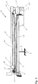
- das Ausführungsbeispiel der erfindungsgemäßen Tragenlagerungseinrichtung in einer Schnittansicht in einer vollständig eingezogenen Stellung zeigt,
- Fig. 2
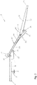
- eine Seitenansicht des Ausführungsbeispiels in einer vollständig ausgezogenen Stellung ist,
- Fig. 3
- eine perspektivische, teilweise aufgebrochene Ansicht eines Teils des Ausführungsbeispiels aus
Fig. 1 zeigt, wobei der Zwischenrahmen und der Oberrahmen in der vollständig ausgezogenen Stellung sind, - Fig. 4
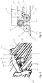
- eine vergrößerte perspektivische Ansicht eines Teils aus
Fig. 3 zeigt, , - Fig. 5
- eine Schnittansicht eines Details aus den
Fig. 1 bis 3 ist, und - Fig. 6.
- eine vergrößerte perspektivische Ansicht eines weiteren Teils aus
Fig. 3 zeigt.
- Fig. 1
- shows the embodiment of the stretcher support device according to the invention in a sectional view in a fully retracted position,
- Fig. 2
- is a side view of the embodiment in a fully extended position;
- Fig. 3
- a perspective, partially broken away view of part of the embodiment
Fig. 1 shows with the intermediate frame and the upper frame in the fully extended position, - Fig. 4
- Figure 3 is an enlarged perspective view of a portion
Fig. 3 shows, , - Fig. 5
- a sectional view of a detail from the
Figs. 1 to 3 is and - Fig. 6.
- FIG. 3 is an enlarged perspective view of another part
Fig. 3 shows.
Wie
Des Weiteren weist die Tragenlagerungseinrichtung 1 einen aus zwei Elementen aufgebauten Unterrahmen 7 auf, der auf dem Untergestell 3 angeordnet und außerdem fest mit diesem verbunden ist. In einem bevorzugten Ausführungsbeispiel ist das Untergestell 3 derart ausgestaltet, dass die Neigung des Unterrahmens 7 relativ zu der Bodenfläche des Laderaums verstellt werden kann. Dies ermöglicht, die Neigung einer auf der Tragenlagerungseinrichtung 1 angebrachten Patiententrage im eingefahrenen Zustand der Tragenlagerungseinrichtung 1 zu verändern.Furthermore, the stretcher mounting device 1 has a subframe 7 made up of two elements, which is arranged on the subframe 3 and is also firmly connected to it. In a preferred exemplary embodiment, the underframe 3 is designed in such a way that the inclination of the underframe 7 can be adjusted relative to the floor area of the cargo space. This makes it possible to change the inclination of a patient stretcher attached to the stretcher mounting device 1 when the stretcher mounting device 1 is in the retracted state.
Der Unterrahmen 7 weist ein Vorderende 9 und ein Beladungsende 11 auf und erstreckt sich zwischen diesen parallel zu der Bodenfläche. Wenn die Tragenlagerungseinrichtung 1 im Laderaum eines Fahrzeugs angeordnet ist, ist das Vorderende 9 entfernt von der Öffnung des Laderaums angeordnet, über die eine Patiententrage in den Laderaum eingebracht wird, während das Beladungsende 11 unmittelbar benachbart dazu positioniert ist.The sub-frame 7 has a
Des Weiteren ist an dem Unterrahmen 7 eine sich zwischen dem Vorderende 9 und dem Beladungsende 11 erstreckende geradlinige erste Führung vorgesehen, wobei diese erste Führung in dem hier beschriebenen Ausführungsbeispiel als geradlinige erste Schienen 13 ausgebildet ist, die an nach außen weisenden Seiten der Elemente des Unterrahmens 7 befestigt sind, sodass die Öffnungen der ersten Schienen 13 nach außen weisen (siehe
Wie außerdem in den
Außerdem ist insbesondere in
Wie die
Ferner weist der Oberrahmen 31 ein erstes Ende 35 und ein zweites Ende 37 auf und ist an dem Zwischenrahmen 15 verschiebbar angebracht. Dabei kann der Oberrahmen 31 relativ zu dem Zwischenrahmen 15 eine eingezogenen Stellung einnehmen, in der der Oberrahmen 31 so über dem Zwischenrahmen 15 angeordnet ist, dass das erste Ende 35 des Oberrahmens 31 an dem ersten Ende 17 des Zwischenrahmens 15 und das zweite Ende 37 des Oberrahmens 31 an dem zweiten Ende 19 des Zwischenrahmens 15 angeordnet sind, wie dies in
Aus
Der Verlauf der zweiten Stützschienen 41 zwischen dem ersten Ende 35 und dem zweiten Ende 37 ist derart, dass sich der Winkel a, den die Beladefläche 33 mit der zweiten Führung bzw. den zweiten Schienen 29 und damit der Ebene des Zwischenrahmes 15 einschließt, verringert, wenn der Oberrahmen 31 von der eingezogenen Stellung in die ausgezogene Stellung bewegt wird.The course of the second support rails 41 between the
In dem hier beschriebenen bevorzugten Ausführungsbeispiel vergrößert sich der Abstand zwischen den zweiten Schienen 29 und den ersten Stützschienen 27 gemessen senkrecht zu den zweiten Schienen 29, vom ersten Ende 17 des Zwischenrahmens 15 hin zum zweiten Ende 19 des Zwischenrahmens 15. Außerdem vergrößert sich in dieser Ausführungsform der Abstand zwischen der Beladefläche 33 und den zweiten Stützschienen 41, gemessen senkrecht zur Ebene der Beladefläche 33, vom zweiten Ende 37 des Oberrahmens 31 hin zum ersten Ende 35 des Oberrahmens 31. Bei dieser Geometrie wird gerade der Effekt erreicht, dass sich der Winkel α zwischen dem Oberrahmen 31 und dem Zwischenrahmen 15 bei der Bewegung des Oberrahmens 31 in die ausgezogene Stellung verringert.In the preferred embodiment described here, the distance between the
Wie die
Dabei ist die Antriebsanordnung derart ausgestaltet, dass die Verschiebebewegung zwischen dem Unterrahmen 7 und dem Zwischenrahmen 15 derart parallel zu der Verschiebebewegung zwischen dem Zwischenrahmen 15 und dem Oberrahmen 31 erfolgt, dass der Zwischenrahmen 15 relativ zu dem Unterrahmen 7 die gleiche Wegstrecke pro Zeiteinheit zurücklegt wie der Oberrahmen 31 relativ zu dem Zwischenrahmen 15.The drive arrangement is designed such that the displacement movement between the lower frame 7 and the
Die Antriebsanordnung weist zunächst ein erstes Eingriffselement in Form eines zweiteiligen Zahnriemens 43 auf, der am Unterrahmen 7 befestigt ist und sich zwischen dessen Vorderende 9 und dessen Beladungsende 11 erstreckt. Ferner ist an dem Zwischenrahmen 15 ein Antriebsmotor (nicht dargestellt) gehaltert, der ein zweites Eingriffselement in Form eines Zahnrades 47 drehend antreibt, wobei das Zahnrad 47 auf einer von der Motorwelle des Antriebsmotors beabstandeten Antriebswelle 49 befestigt ist, die drehbar im Zwischenrahmen 15 gehaltert ist (siehe
Bei diesem Aufbau bewirkt eine Drehung des Zahnrads 47 die Verschiebebewegung des Zwischenrahmens 15 relativ zu dem Unterrahmen 7, da der Zwischenrahmen 15 bei einer Drehung des Zahnrades 47 entlang des Zahnriemens 43 gezogen wird.In this structure, a rotation of the
Schließlich ist an dem Zwischenrahmen 15 ein umlaufender Antriebsriemen 61 über eine Antriebsrolle 63 und eine weitere Rolle 65 geführt, wobei die Antriebsrolle 63 an der Antriebswelle 49 befestigt ist und damit zusammen mit dem Zahnrad 47 von dem Antriebsmotor drehend angetrieben wird (siehe
Die zuvor beschriebene Tragenlagerungseinrichtung 1 kann aus der in
Zum einen wird durch den Eingriff des Zahnrads 47 mit dem Zahnriemen 43 der Zwischenrahmen 15 über das Beladungsende 11 des Unterrahmens 7 aus dem nicht dargestellten Laderaum nach außen gezogen, wobei er sich aufgrund der Anlage der ersten Stützschienen 27 mit den ersten Abstützelementen 25 zunehmend nach unten neigt.On the one hand, the engagement of the
Zum anderen wird durch Drehung der Antriebsrolle 63 der Antriebsriemen 61 mit dem Kopplungsstück 67 bewegt, sodass sich das zweite Ende 37 des Oberrahmens 31 über das zweite Ende 19 des Zwischenrahmens 15 hinaus bewegt und dabei aufgrund der Form der zweiten Stützschienen 41 so gegenüber dem Zwischenrahmen 15 nach oben schwenkt, dass sich der Winkel a zwischen der Beladefläche 33 und dem Zwischenrahmen 15 verringert. Dies kompensiert die zunehmende Neigung des Zwischenrahmens 15 gegenüber der Horizontalen, sodass die Neigung der Beladefläche 33 und einer darauf angebrachten Patiententrage einen Grenzwinkel von beispielsweise 160 nicht überschreitet.On the other hand, by rotating the
Diese Kompensation der Kippbewegung des Zwischenrahmens 15 nach unten durch eine Kippbewegung des Oberrahmens 31 relativ zu dem Zwischenrahmen 15 nach oben wird bei dem Ausführungsbeispiel durch eine Ausgestaltung der ersten und zweiten Stützschienen 27, 41 am Zwischenrahmen 15 und Oberrahmen 31 in Form einer "Doppelkurvengeometrie" erreicht. Konkret bedeutet dies, dass die ersten Stützschienen 27, mit denen sich der Zwischenrahmen 15 am Unterrahmen 7 abstützt, einen ersten, ggf. kurvenförmigen Verlauf haben. Dieser bewirkt beim Ausfahren des Zwischenrahmens 15 dessen Kippbewegung nach unten. Die zweiten Stützschienen 41 am Oberrahmen 31, mit denen dieser sich am Zwischenrahmen 15 abstützt, haben einen zweiten, ggf. ebenfalls kurvenförmigen Verlauf, der gerade dem kurvenförmigen Verlauf der ersten Stützschienen 27 entgegengesetzt ist. Diese doppelten Kurven führen gerade dazu, dass beim Ausfahren die zunehmende Neigung des Zwischenrahmens 15 durch eine Schwenkbewegung des Oberrahmens 31 kompensiert wird.This compensation of the tilting movement of the
Die Bewegung aus der ausgezogenen Stellung zurück in die eingezogene Stellung läuft dann in der umgekehrten Weise ab und auch dann wird der Grenzwinkel natürlich nicht überschritten.The movement from the extended position back to the retracted position then takes place in the opposite way and even then the critical angle is of course not exceeded.
Dadurch, dass der Zwischenrahmen 15 während der Bewegung aber größere Neigungswinkel als der Grenzwinkel annimmt, ist die Gesamtlänge der Tragenlagerungseinrichtung 1 in der ausgezogenen Stellung (siehe
- 11
- TragenlagerungseinrichtungStretcher storage facility
- 33
- UntergestellUnderframe
- 55
- Unterseitebottom
- 77th
- UnterrahmenSubframe
- 99
- VorderendeFront end
- 1111
- BeladungsendeEnd of loading
- 1313
- erste Schienenfirst rails
- 1515th
- ZwischenrahmenIntermediate frame
- 1717th
- erstes Ende - Zwischenrahmenfirst end - intermediate frame
- 1919th
- zweites Ende - Zwischenrahmensecond end - intermediate frame
- 2121st
- Armepoor
- 2323
- DrehlagerPivot bearing
- 2525th
- erste Abstützelementefirst support elements
- 2727
- erste Stützschienenfirst support rails
- 2929
- zweite Schienensecond rails
- 3131
- OberrahmenUpper frame
- 3333
- BeladeflächeLoading area
- 3535
- erstes Ende - Oberrahmenfirst end - upper frame
- 3737
- zweites Ende - Oberrahmensecond end - upper frame
- 3939
- zweite Abstützelementesecond support elements
- 4141
- zweite Stützschienensecond support rails
- 4343
- ZahnriemenTiming belt
- 4747
- Zahnradgear
- 4949
- Antriebswelledrive shaft
- 5151
- Halterholder
- 5353
- erste Umlenkrollefirst pulley
- 5555
- zweite Umlenkrollesecond pulley
- 5757
- DrehachsenAxes of rotation
- 5959
- DrehachsenebeneAxis of rotation plane
- 6161
- AntriebsriemenDrive belt
- 6363
- AntriebsrolleDrive roller
- 6565
- Rollerole
- 6767
- KopplungsstückCoupling piece
- 6969
- Halterholder
Claims (13)
- Stretcher support device (1) with a bogie (3), the latter being designed to be connected to the structure of a vehicle such that the stretcher support device is arranged in a loading space of the vehicle,with a bottom frame (7), which is arranged on the bogie (3) and is rigidly connected to the latter, wherein the bottom frame (7) has a front end (9) and a loading end (11) and extends between these parallel to a floor surface,with a middle frame (15), which has a first end (17) and a second end (19) and which is mounted displaceably on the bottom frame (7) in such a way that it can be moved relative to the bottom frame (7) between a retracted position, in which the middle frame (15) is arranged over the bottom frame (7) so that the first end (17) of the middle frame (15) is arranged at the front end (9) and the second end (19) of the middle frame (15) is arranged at the loading end (11), and a deployed position, in which the middle frame (15) extends beyond the loading end (11) ,with a top frame (31), which has a flat loading surface (33) and also a first end (35) and a second end (37) and which is mounted displaceably on the middle frame (15) in such a way that it can be moved relative to the middle frame (15) between a retracted position, in which the top frame (31) is arranged over the middle frame (15) so that the first end (35) of the top frame (31) is arranged at the first end (17) of the middle frame (15) and the second end (37) of the top frame (31) is arranged at the second end (19) of the middle frame (15), and a deployed position, in which the top frame (31) extends beyond the second end (19) of the middle frame (15),wherein the bottom frame (7) has a first guide, which extends between the front end (9) and the loading end (11) and along which at least the first end (17) of the middle frame (15) is guided displaceably,wherein the loading end (11) has a first supporting element (25), on which a first support rail (27) of the middle frame (15) is supported, said first support rail (27) facing towards the floor surface and extending between the first end (17) and the second end (19) of the middle frame (15) ,wherein the middle frame (15) has a second guide, which extends between the first end (17) and the second end (19) and along which at least the first end (35) of the top frame (31) is guided displaceably,wherein the second end (19) of the middle frame (15) has a second supporting element (39), on which a second support rail (41) of the top frame (31) is supported, said second support rail (41) facing towards the floor surface and extending between the first end (35) and the second end (37) of the top frame (31), andwherein the course of the second support rail (41) between the first end (35) and the second end (37) of the top frame (31) is such that the angle (α), which the loading surface (33) encloses with the middle frame (15), decreases when the top frame (31) is moved from the retracted position to the deployed position.
- Stretcher support device (1) according to Claim 1, wherein the first guide and the second guide are straight,wherein the distance between the second guide and the first support rail (27), measured perpendicular to the second guide, increases from the first end (17) of the middle frame (15) towards the second end (19) of the middle frame (15), and/orwherein the distance between the loading surface (33) and the second support rail (41), measured perpendicular to the plane of the loading surface (33), increases from the second end (37) of the top frame (31) towards the first end (35) of the top frame (31).
- Stretcher support device (1) according to Claim 1 or 2, wherein the first end (17) of the middle frame (15) is mounted pivotably on the bottom frame (7) and
wherein the first end (35) of the top frame (31) is mounted pivotably on the middle frame (15). - Stretcher support device (1) according to one or more of Claims 1 to 3, wherein the first guide has first rails (13), in which rotary bearings (23) mounted on the first end (17) of the middle frame (15) are guided.
- Stretcher support device (1) according to one or more of Claims 1 to 4, wherein the second guide has second rails (29), in which rotary bearings mounted on the first end (35) of the top frame (31) are guided.
- Stretcher support device (1) according to one or more of Claims 1 to 5, wherein a drive arrangement is provided, which is designed to displace the middle frame (15) relative to the bottom frame (7) between the retracted position and the deployed position and to displace the top frame (31) relative to the middle frame (15) between the retracted position and the deployed position.
- Stretcher support device (1) according to Claim 6, wherein the drive arrangement is designed in such a way that the displacement movement between the bottom frame (7) and the middle frame (15) takes place parallel to the displacement movement between the middle frame (15) and the top frame (31), in such a way that the middle frame (15) travels relative to the bottom frame (7) by the same distance per unit of time as the top frame (31) travels relative to the middle frame (15).
- Stretcher support device (1) according to Claim 6 or 7, wherein the drive arrangement has a first engagement element on the bottom frame (7), which first engagement element extends between the front end (9) and the loading end (11), and
wherein a drive motor is mounted on the middle frame (15) and drives a second engagement element in rotation, wherein the first engagement element and the second engagement element are in engagement with each other in such a way that a rotation of the second engagement element brings about the displacement movement of the middle frame (15) relative to the bottom frame (7). - Stretcher support device (1) according to Claim 8, wherein the first engagement element is designed as a toothed belt (43), and the second engagement element is designed as a toothed wheel (47) that meshes with the toothed belt (43).
- Stretcher support device (1) according to Claim 8 or 9, wherein the second engagement element is secured on a drive shaft (49), which is driven in rotation by the drive motor and which is mounted rotatably on the middle frame (15).
- Stretcher support device (1) according to Claims 9 and 10, wherein a retainer (51) is mounted on the drive shaft (49) in such a way as to be pivotable about the latter, and a first deflection roller (53) and a second deflection roller (55) are mounted on the retainer (51) in such a way as to be rotatable about rotation axes (57),wherein the rotation axes (57) extend parallel to the drive shaft (49) and in a rotation axis plane (59), which is parallel and offset with respect to the drive shaft (49),wherein the rotation axes (57) are arranged in the rotation axis plane (59) at a lateral distance from the projection of the drive shaft (49) onto the rotation axis plane (59), andwherein the toothed belt (43) is guided about the first deflection roller (53), the toothed wheel (47) and the second deflection roller (55).
- Stretcher support device (1) according to one or more of Claims 3 to 11, wherein a peripheral drive belt (61) on the middle frame (15) is mounted on a drive roller (63) and at least one further roller (65),wherein the drive roller (63) is driven in rotation andwherein a coupling piece (67), which is connected to the top frame (31), is secured on the drive belt (61) .
- Stretcher support device (1) according to Claims 10 and 12, wherein the drive roller (63) is secured on the drive shaft (49).
Priority Applications (3)
| Application Number | Priority Date | Filing Date | Title |
|---|---|---|---|
| ES18174201T ES2865430T3 (en) | 2018-05-24 | 2018-05-24 | Stretcher support device |
| EP18174201.6A EP3572056B1 (en) | 2018-05-24 | 2018-05-24 | Stretcher support device |
| PL18174201T PL3572056T3 (en) | 2018-05-24 | 2018-05-24 | Stretcher support device |
Applications Claiming Priority (1)
| Application Number | Priority Date | Filing Date | Title |
|---|---|---|---|
| EP18174201.6A EP3572056B1 (en) | 2018-05-24 | 2018-05-24 | Stretcher support device |
Publications (2)
| Publication Number | Publication Date |
|---|---|
| EP3572056A1 EP3572056A1 (en) | 2019-11-27 |
| EP3572056B1 true EP3572056B1 (en) | 2020-12-16 |
Family
ID=62567236
Family Applications (1)
| Application Number | Title | Priority Date | Filing Date |
|---|---|---|---|
| EP18174201.6A Active EP3572056B1 (en) | 2018-05-24 | 2018-05-24 | Stretcher support device |
Country Status (3)
| Country | Link |
|---|---|
| EP (1) | EP3572056B1 (en) |
| ES (1) | ES2865430T3 (en) |
| PL (1) | PL3572056T3 (en) |
Family Cites Families (4)
| Publication number | Priority date | Publication date | Assignee | Title |
|---|---|---|---|---|
| DE202009015121U1 (en) * | 2009-11-06 | 2010-01-21 | System Strobel Gmbh & Co. Kg | Device for receiving a stretcher |
| US9017003B2 (en) * | 2010-02-22 | 2015-04-28 | Am General Llc | Loading device |
| DE102010012065A1 (en) * | 2010-03-19 | 2011-09-22 | Eads Deutschland Gmbh | wear module |
| DE102015002448B4 (en) * | 2015-02-26 | 2018-05-30 | Airbus Defence and Space GmbH | Carrying loading system and ambulance |
-
2018
- 2018-05-24 ES ES18174201T patent/ES2865430T3/en active Active
- 2018-05-24 EP EP18174201.6A patent/EP3572056B1/en active Active
- 2018-05-24 PL PL18174201T patent/PL3572056T3/en unknown
Non-Patent Citations (1)
| Title |
|---|
| None * |
Also Published As
| Publication number | Publication date |
|---|---|
| ES2865430T3 (en) | 2021-10-15 |
| PL3572056T3 (en) | 2021-08-16 |
| EP3572056A1 (en) | 2019-11-27 |
Similar Documents
| Publication | Publication Date | Title |
|---|---|---|
| EP0395847B1 (en) | Actuator assembly for a motorised folding top | |
| EP1587701B1 (en) | Pivoting sliding door for vehicles | |
| AT405155B (en) | SLIDING SLIDING DOOR FOR VEHICLES | |
| DE3916976C2 (en) | ||
| DE10145476B4 (en) | Free articulated arm system for precise control | |
| DE3027835A1 (en) | OPTIONAL TILT OR PARALLEL DETACHABLE LEAF OF A WINDOW, DOOR OR THE LIKE. | |
| DE19828464C1 (en) | Device for operating a lifting sunroof | |
| DE102015207736B4 (en) | Mobile C-arm X-ray machine | |
| EP3572056B1 (en) | Stretcher support device | |
| DE10250905B4 (en) | Adjustment device for a steering wheel of a truck | |
| DE1104713B (en) | Device for tilting a support | |
| DE2633683C2 (en) | Transport vehicle for prefabricated garages and the like | |
| DE202014105344U1 (en) | Universal manipulator | |
| DE19737678A1 (en) | Vehicle with frame support | |
| DE2529556A1 (en) | DEVICE FOR ADJUSTING A VEHICLE SEAT | |
| DE10065130B4 (en) | Windshield for motorcycles | |
| DE102019120300B3 (en) | Drive device for lifting beds | |
| DE3431498C1 (en) | Lifting and swiveling device for the discharge section of a tubular chute | |
| EP0788767A1 (en) | X-ray diagnostic apparatus | |
| DE102015008649A1 (en) | Vehicle seat and vehicle | |
| DE102009041862A1 (en) | Camera dolly has column for holding camera, where column is adjusted at lower position around pre-determined distance of five hundred millimeter | |
| CH708120A2 (en) | Universal Manipulator. | |
| DE2638566C3 (en) | Outdoor conveyor with a closed track for multiple trolleys | |
| EP3425152A1 (en) | Pivotable sliding door | |
| DE102022113665B3 (en) | vehicle body conveyor |
Legal Events
| Date | Code | Title | Description |
|---|---|---|---|
| PUAI | Public reference made under article 153(3) epc to a published international application that has entered the european phase |
Free format text: ORIGINAL CODE: 0009012 |
|
| STAA | Information on the status of an ep patent application or granted ep patent |
Free format text: STATUS: THE APPLICATION HAS BEEN PUBLISHED |
|
| AK | Designated contracting states |
Kind code of ref document: A1 Designated state(s): AL AT BE BG CH CY CZ DE DK EE ES FI FR GB GR HR HU IE IS IT LI LT LU LV MC MK MT NL NO PL PT RO RS SE SI SK SM TR |
|
| AX | Request for extension of the european patent |
Extension state: BA ME |
|
| STAA | Information on the status of an ep patent application or granted ep patent |
Free format text: STATUS: REQUEST FOR EXAMINATION WAS MADE |
|
| 17P | Request for examination filed |
Effective date: 20200401 |
|
| RBV | Designated contracting states (corrected) |
Designated state(s): AL AT BE BG CH CY CZ DE DK EE ES FI FR GB GR HR HU IE IS IT LI LT LU LV MC MK MT NL NO PL PT RO RS SE SI SK SM TR |
|
| GRAP | Despatch of communication of intention to grant a patent |
Free format text: ORIGINAL CODE: EPIDOSNIGR1 |
|
| STAA | Information on the status of an ep patent application or granted ep patent |
Free format text: STATUS: GRANT OF PATENT IS INTENDED |
|
| INTG | Intention to grant announced |
Effective date: 20200629 |
|
| GRAS | Grant fee paid |
Free format text: ORIGINAL CODE: EPIDOSNIGR3 |
|
| GRAA | (expected) grant |
Free format text: ORIGINAL CODE: 0009210 |
|
| STAA | Information on the status of an ep patent application or granted ep patent |
Free format text: STATUS: THE PATENT HAS BEEN GRANTED |
|
| AK | Designated contracting states |
Kind code of ref document: B1 Designated state(s): AL AT BE BG CH CY CZ DE DK EE ES FI FR GB GR HR HU IE IS IT LI LT LU LV MC MK MT NL NO PL PT RO RS SE SI SK SM TR |
|
| REG | Reference to a national code |
Ref country code: GB Ref legal event code: FG4D Free format text: NOT ENGLISH |
|
| REG | Reference to a national code |
Ref country code: DE Ref legal event code: R096 Ref document number: 502018003298 Country of ref document: DE |
|
| REG | Reference to a national code |
Ref country code: IE Ref legal event code: FG4D Free format text: LANGUAGE OF EP DOCUMENT: GERMAN |
|
| REG | Reference to a national code |
Ref country code: AT Ref legal event code: REF Ref document number: 1344911 Country of ref document: AT Kind code of ref document: T Effective date: 20210115 |
|
| REG | Reference to a national code |
Ref country code: FI Ref legal event code: FGE |
|
| PG25 | Lapsed in a contracting state [announced via postgrant information from national office to epo] |
Ref country code: RS Free format text: LAPSE BECAUSE OF FAILURE TO SUBMIT A TRANSLATION OF THE DESCRIPTION OR TO PAY THE FEE WITHIN THE PRESCRIBED TIME-LIMIT Effective date: 20201216 Ref country code: NO Free format text: LAPSE BECAUSE OF FAILURE TO SUBMIT A TRANSLATION OF THE DESCRIPTION OR TO PAY THE FEE WITHIN THE PRESCRIBED TIME-LIMIT Effective date: 20210316 Ref country code: GR Free format text: LAPSE BECAUSE OF FAILURE TO SUBMIT A TRANSLATION OF THE DESCRIPTION OR TO PAY THE FEE WITHIN THE PRESCRIBED TIME-LIMIT Effective date: 20210317 |
|
| REG | Reference to a national code |
Ref country code: NL Ref legal event code: MP Effective date: 20201216 |
|
| PG25 | Lapsed in a contracting state [announced via postgrant information from national office to epo] |
Ref country code: BG Free format text: LAPSE BECAUSE OF FAILURE TO SUBMIT A TRANSLATION OF THE DESCRIPTION OR TO PAY THE FEE WITHIN THE PRESCRIBED TIME-LIMIT Effective date: 20210316 Ref country code: LV Free format text: LAPSE BECAUSE OF FAILURE TO SUBMIT A TRANSLATION OF THE DESCRIPTION OR TO PAY THE FEE WITHIN THE PRESCRIBED TIME-LIMIT Effective date: 20201216 Ref country code: SE Free format text: LAPSE BECAUSE OF FAILURE TO SUBMIT A TRANSLATION OF THE DESCRIPTION OR TO PAY THE FEE WITHIN THE PRESCRIBED TIME-LIMIT Effective date: 20201216 |
|
| PG25 | Lapsed in a contracting state [announced via postgrant information from national office to epo] |
Ref country code: NL Free format text: LAPSE BECAUSE OF FAILURE TO SUBMIT A TRANSLATION OF THE DESCRIPTION OR TO PAY THE FEE WITHIN THE PRESCRIBED TIME-LIMIT Effective date: 20201216 Ref country code: HR Free format text: LAPSE BECAUSE OF FAILURE TO SUBMIT A TRANSLATION OF THE DESCRIPTION OR TO PAY THE FEE WITHIN THE PRESCRIBED TIME-LIMIT Effective date: 20201216 |
|
| REG | Reference to a national code |
Ref country code: LT Ref legal event code: MG9D |
|
| PG25 | Lapsed in a contracting state [announced via postgrant information from national office to epo] |
Ref country code: SM Free format text: LAPSE BECAUSE OF FAILURE TO SUBMIT A TRANSLATION OF THE DESCRIPTION OR TO PAY THE FEE WITHIN THE PRESCRIBED TIME-LIMIT Effective date: 20201216 Ref country code: LT Free format text: LAPSE BECAUSE OF FAILURE TO SUBMIT A TRANSLATION OF THE DESCRIPTION OR TO PAY THE FEE WITHIN THE PRESCRIBED TIME-LIMIT Effective date: 20201216 Ref country code: SK Free format text: LAPSE BECAUSE OF FAILURE TO SUBMIT A TRANSLATION OF THE DESCRIPTION OR TO PAY THE FEE WITHIN THE PRESCRIBED TIME-LIMIT Effective date: 20201216 Ref country code: PT Free format text: LAPSE BECAUSE OF FAILURE TO SUBMIT A TRANSLATION OF THE DESCRIPTION OR TO PAY THE FEE WITHIN THE PRESCRIBED TIME-LIMIT Effective date: 20210416 Ref country code: RO Free format text: LAPSE BECAUSE OF FAILURE TO SUBMIT A TRANSLATION OF THE DESCRIPTION OR TO PAY THE FEE WITHIN THE PRESCRIBED TIME-LIMIT Effective date: 20201216 Ref country code: EE Free format text: LAPSE BECAUSE OF FAILURE TO SUBMIT A TRANSLATION OF THE DESCRIPTION OR TO PAY THE FEE WITHIN THE PRESCRIBED TIME-LIMIT Effective date: 20201216 |
|
| REG | Reference to a national code |
Ref country code: DE Ref legal event code: R097 Ref document number: 502018003298 Country of ref document: DE |
|
| PG25 | Lapsed in a contracting state [announced via postgrant information from national office to epo] |
Ref country code: IS Free format text: LAPSE BECAUSE OF FAILURE TO SUBMIT A TRANSLATION OF THE DESCRIPTION OR TO PAY THE FEE WITHIN THE PRESCRIBED TIME-LIMIT Effective date: 20210416 |
|
| REG | Reference to a national code |
Ref country code: ES Ref legal event code: FG2A Ref document number: 2865430 Country of ref document: ES Kind code of ref document: T3 Effective date: 20211015 |
|
| PLBE | No opposition filed within time limit |
Free format text: ORIGINAL CODE: 0009261 |
|
| STAA | Information on the status of an ep patent application or granted ep patent |
Free format text: STATUS: NO OPPOSITION FILED WITHIN TIME LIMIT |
|
| PG25 | Lapsed in a contracting state [announced via postgrant information from national office to epo] |
Ref country code: AL Free format text: LAPSE BECAUSE OF FAILURE TO SUBMIT A TRANSLATION OF THE DESCRIPTION OR TO PAY THE FEE WITHIN THE PRESCRIBED TIME-LIMIT Effective date: 20201216 |
|
| 26N | No opposition filed |
Effective date: 20210917 |
|
| PG25 | Lapsed in a contracting state [announced via postgrant information from national office to epo] |
Ref country code: DK Free format text: LAPSE BECAUSE OF FAILURE TO SUBMIT A TRANSLATION OF THE DESCRIPTION OR TO PAY THE FEE WITHIN THE PRESCRIBED TIME-LIMIT Effective date: 20201216 |
|
| REG | Reference to a national code |
Ref country code: CH Ref legal event code: PL |
|
| PG25 | Lapsed in a contracting state [announced via postgrant information from national office to epo] |
Ref country code: CH Free format text: LAPSE BECAUSE OF NON-PAYMENT OF DUE FEES Effective date: 20210531 Ref country code: MC Free format text: LAPSE BECAUSE OF FAILURE TO SUBMIT A TRANSLATION OF THE DESCRIPTION OR TO PAY THE FEE WITHIN THE PRESCRIBED TIME-LIMIT Effective date: 20201216 Ref country code: LU Free format text: LAPSE BECAUSE OF NON-PAYMENT OF DUE FEES Effective date: 20210524 Ref country code: LI Free format text: LAPSE BECAUSE OF NON-PAYMENT OF DUE FEES Effective date: 20210531 |
|
| REG | Reference to a national code |
Ref country code: BE Ref legal event code: MM Effective date: 20210531 |
|
| PG25 | Lapsed in a contracting state [announced via postgrant information from national office to epo] |
Ref country code: SI Free format text: LAPSE BECAUSE OF FAILURE TO SUBMIT A TRANSLATION OF THE DESCRIPTION OR TO PAY THE FEE WITHIN THE PRESCRIBED TIME-LIMIT Effective date: 20201216 |
|
| PG25 | Lapsed in a contracting state [announced via postgrant information from national office to epo] |
Ref country code: LI Free format text: LAPSE BECAUSE OF NON-PAYMENT OF DUE FEES Effective date: 20210531 Ref country code: IE Free format text: LAPSE BECAUSE OF NON-PAYMENT OF DUE FEES Effective date: 20210524 Ref country code: CH Free format text: LAPSE BECAUSE OF NON-PAYMENT OF DUE FEES Effective date: 20210531 |
|
| PGRI | Patent reinstated in contracting state [announced from national office to epo] |
Ref country code: LI Effective date: 20220110 Ref country code: CH Effective date: 20220110 |
|
| PG25 | Lapsed in a contracting state [announced via postgrant information from national office to epo] |
Ref country code: IS Free format text: LAPSE BECAUSE OF FAILURE TO SUBMIT A TRANSLATION OF THE DESCRIPTION OR TO PAY THE FEE WITHIN THE PRESCRIBED TIME-LIMIT Effective date: 20210416 |
|
| PG25 | Lapsed in a contracting state [announced via postgrant information from national office to epo] |
Ref country code: BE Free format text: LAPSE BECAUSE OF NON-PAYMENT OF DUE FEES Effective date: 20210531 |
|
| REG | Reference to a national code |
Ref country code: CH Ref legal event code: PL |
|
| PG25 | Lapsed in a contracting state [announced via postgrant information from national office to epo] |
Ref country code: LI Free format text: LAPSE BECAUSE OF NON-PAYMENT OF DUE FEES Effective date: 20220531 Ref country code: CH Free format text: LAPSE BECAUSE OF NON-PAYMENT OF DUE FEES Effective date: 20220531 |
|
| PGRI | Patent reinstated in contracting state [announced from national office to epo] |
Ref country code: LI Effective date: 20230106 Ref country code: CH Effective date: 20230106 |
|
| PG25 | Lapsed in a contracting state [announced via postgrant information from national office to epo] |
Ref country code: CY Free format text: LAPSE BECAUSE OF FAILURE TO SUBMIT A TRANSLATION OF THE DESCRIPTION OR TO PAY THE FEE WITHIN THE PRESCRIBED TIME-LIMIT Effective date: 20201216 |
|
| PG25 | Lapsed in a contracting state [announced via postgrant information from national office to epo] |
Ref country code: HU Free format text: LAPSE BECAUSE OF FAILURE TO SUBMIT A TRANSLATION OF THE DESCRIPTION OR TO PAY THE FEE WITHIN THE PRESCRIBED TIME-LIMIT; INVALID AB INITIO Effective date: 20180524 |
|
| PGFP | Annual fee paid to national office [announced via postgrant information from national office to epo] |
Ref country code: IT Payment date: 20230531 Year of fee payment: 6 Ref country code: FR Payment date: 20230517 Year of fee payment: 6 Ref country code: ES Payment date: 20230621 Year of fee payment: 6 Ref country code: DE Payment date: 20230519 Year of fee payment: 6 Ref country code: CZ Payment date: 20230512 Year of fee payment: 6 Ref country code: CH Payment date: 20230602 Year of fee payment: 6 |
|
| PGFP | Annual fee paid to national office [announced via postgrant information from national office to epo] |
Ref country code: PL Payment date: 20230511 Year of fee payment: 6 Ref country code: FI Payment date: 20230523 Year of fee payment: 6 Ref country code: AT Payment date: 20230516 Year of fee payment: 6 |
|
| PGFP | Annual fee paid to national office [announced via postgrant information from national office to epo] |
Ref country code: GB Payment date: 20230522 Year of fee payment: 6 |