EP3572049A2 - Orthopädisches prothesensystem für eine achsstielknieprothese - Google Patents
Orthopädisches prothesensystem für eine achsstielknieprothese Download PDFInfo
- Publication number
- EP3572049A2 EP3572049A2 EP19171270.2A EP19171270A EP3572049A2 EP 3572049 A2 EP3572049 A2 EP 3572049A2 EP 19171270 A EP19171270 A EP 19171270A EP 3572049 A2 EP3572049 A2 EP 3572049A2
- Authority
- EP
- European Patent Office
- Prior art keywords
- femoral component
- bracket
- modular insert
- flange
- sized
- Prior art date
- Legal status (The legal status is an assumption and is not a legal conclusion. Google has not performed a legal analysis and makes no representation as to the accuracy of the status listed.)
- Granted
Links
Images


Classifications
-
- A—HUMAN NECESSITIES
- A61—MEDICAL OR VETERINARY SCIENCE; HYGIENE
- A61F—FILTERS IMPLANTABLE INTO BLOOD VESSELS; PROSTHESES; DEVICES PROVIDING PATENCY TO, OR PREVENTING COLLAPSING OF, TUBULAR STRUCTURES OF THE BODY, e.g. STENTS; ORTHOPAEDIC, NURSING OR CONTRACEPTIVE DEVICES; FOMENTATION; TREATMENT OR PROTECTION OF EYES OR EARS; BANDAGES, DRESSINGS OR ABSORBENT PADS; FIRST-AID KITS
- A61F2/00—Filters implantable into blood vessels; Prostheses, i.e. artificial substitutes or replacements for parts of the body; Appliances for connecting them with the body; Devices providing patency to, or preventing collapsing of, tubular structures of the body, e.g. stents
- A61F2/02—Prostheses implantable into the body
- A61F2/30—Joints
- A61F2/38—Joints for elbows or knees
- A61F2/3859—Femoral components
-
- A—HUMAN NECESSITIES
- A61—MEDICAL OR VETERINARY SCIENCE; HYGIENE
- A61F—FILTERS IMPLANTABLE INTO BLOOD VESSELS; PROSTHESES; DEVICES PROVIDING PATENCY TO, OR PREVENTING COLLAPSING OF, TUBULAR STRUCTURES OF THE BODY, e.g. STENTS; ORTHOPAEDIC, NURSING OR CONTRACEPTIVE DEVICES; FOMENTATION; TREATMENT OR PROTECTION OF EYES OR EARS; BANDAGES, DRESSINGS OR ABSORBENT PADS; FIRST-AID KITS
- A61F2/00—Filters implantable into blood vessels; Prostheses, i.e. artificial substitutes or replacements for parts of the body; Appliances for connecting them with the body; Devices providing patency to, or preventing collapsing of, tubular structures of the body, e.g. stents
- A61F2/02—Prostheses implantable into the body
- A61F2/30—Joints
- A61F2/38—Joints for elbows or knees
- A61F2/3836—Special connection between upper and lower leg, e.g. constrained
- A61F2/384—Special connection between upper and lower leg, e.g. constrained hinged, i.e. with transverse axle restricting the movement
- A61F2/385—Special connection between upper and lower leg, e.g. constrained hinged, i.e. with transverse axle restricting the movement also provided with condylar bearing surfaces
-
- A—HUMAN NECESSITIES
- A61—MEDICAL OR VETERINARY SCIENCE; HYGIENE
- A61F—FILTERS IMPLANTABLE INTO BLOOD VESSELS; PROSTHESES; DEVICES PROVIDING PATENCY TO, OR PREVENTING COLLAPSING OF, TUBULAR STRUCTURES OF THE BODY, e.g. STENTS; ORTHOPAEDIC, NURSING OR CONTRACEPTIVE DEVICES; FOMENTATION; TREATMENT OR PROTECTION OF EYES OR EARS; BANDAGES, DRESSINGS OR ABSORBENT PADS; FIRST-AID KITS
- A61F2/00—Filters implantable into blood vessels; Prostheses, i.e. artificial substitutes or replacements for parts of the body; Appliances for connecting them with the body; Devices providing patency to, or preventing collapsing of, tubular structures of the body, e.g. stents
- A61F2/02—Prostheses implantable into the body
- A61F2/30—Joints
- A61F2/38—Joints for elbows or knees
- A61F2/3868—Joints for elbows or knees with sliding tibial bearing
-
- A—HUMAN NECESSITIES
- A61—MEDICAL OR VETERINARY SCIENCE; HYGIENE
- A61F—FILTERS IMPLANTABLE INTO BLOOD VESSELS; PROSTHESES; DEVICES PROVIDING PATENCY TO, OR PREVENTING COLLAPSING OF, TUBULAR STRUCTURES OF THE BODY, e.g. STENTS; ORTHOPAEDIC, NURSING OR CONTRACEPTIVE DEVICES; FOMENTATION; TREATMENT OR PROTECTION OF EYES OR EARS; BANDAGES, DRESSINGS OR ABSORBENT PADS; FIRST-AID KITS
- A61F2/00—Filters implantable into blood vessels; Prostheses, i.e. artificial substitutes or replacements for parts of the body; Appliances for connecting them with the body; Devices providing patency to, or preventing collapsing of, tubular structures of the body, e.g. stents
- A61F2/02—Prostheses implantable into the body
- A61F2/30—Joints
- A61F2/38—Joints for elbows or knees
- A61F2/389—Tibial components
-
- A—HUMAN NECESSITIES
- A61—MEDICAL OR VETERINARY SCIENCE; HYGIENE
- A61F—FILTERS IMPLANTABLE INTO BLOOD VESSELS; PROSTHESES; DEVICES PROVIDING PATENCY TO, OR PREVENTING COLLAPSING OF, TUBULAR STRUCTURES OF THE BODY, e.g. STENTS; ORTHOPAEDIC, NURSING OR CONTRACEPTIVE DEVICES; FOMENTATION; TREATMENT OR PROTECTION OF EYES OR EARS; BANDAGES, DRESSINGS OR ABSORBENT PADS; FIRST-AID KITS
- A61F2/00—Filters implantable into blood vessels; Prostheses, i.e. artificial substitutes or replacements for parts of the body; Appliances for connecting them with the body; Devices providing patency to, or preventing collapsing of, tubular structures of the body, e.g. stents
- A61F2/02—Prostheses implantable into the body
- A61F2/30—Joints
- A61F2002/30001—Additional features of subject-matter classified in A61F2/28, A61F2/30 and subgroups thereof
- A61F2002/30316—The prosthesis having different structural features at different locations within the same prosthesis; Connections between prosthetic parts; Special structural features of bone or joint prostheses not otherwise provided for
- A61F2002/30329—Connections or couplings between prosthetic parts, e.g. between modular parts; Connecting elements
- A61F2002/30433—Connections or couplings between prosthetic parts, e.g. between modular parts; Connecting elements using additional screws, bolts, dowels, rivets or washers e.g. connecting screws
-
- A—HUMAN NECESSITIES
- A61—MEDICAL OR VETERINARY SCIENCE; HYGIENE
- A61F—FILTERS IMPLANTABLE INTO BLOOD VESSELS; PROSTHESES; DEVICES PROVIDING PATENCY TO, OR PREVENTING COLLAPSING OF, TUBULAR STRUCTURES OF THE BODY, e.g. STENTS; ORTHOPAEDIC, NURSING OR CONTRACEPTIVE DEVICES; FOMENTATION; TREATMENT OR PROTECTION OF EYES OR EARS; BANDAGES, DRESSINGS OR ABSORBENT PADS; FIRST-AID KITS
- A61F2/00—Filters implantable into blood vessels; Prostheses, i.e. artificial substitutes or replacements for parts of the body; Appliances for connecting them with the body; Devices providing patency to, or preventing collapsing of, tubular structures of the body, e.g. stents
- A61F2/02—Prostheses implantable into the body
- A61F2/30—Joints
- A61F2002/30001—Additional features of subject-matter classified in A61F2/28, A61F2/30 and subgroups thereof
- A61F2002/30316—The prosthesis having different structural features at different locations within the same prosthesis; Connections between prosthetic parts; Special structural features of bone or joint prostheses not otherwise provided for
- A61F2002/30329—Connections or couplings between prosthetic parts, e.g. between modular parts; Connecting elements
- A61F2002/30471—Connections or couplings between prosthetic parts, e.g. between modular parts; Connecting elements connected by a hinged linkage mechanism, e.g. of the single-bar or multi-bar linkage type
-
- A—HUMAN NECESSITIES
- A61—MEDICAL OR VETERINARY SCIENCE; HYGIENE
- A61F—FILTERS IMPLANTABLE INTO BLOOD VESSELS; PROSTHESES; DEVICES PROVIDING PATENCY TO, OR PREVENTING COLLAPSING OF, TUBULAR STRUCTURES OF THE BODY, e.g. STENTS; ORTHOPAEDIC, NURSING OR CONTRACEPTIVE DEVICES; FOMENTATION; TREATMENT OR PROTECTION OF EYES OR EARS; BANDAGES, DRESSINGS OR ABSORBENT PADS; FIRST-AID KITS
- A61F2/00—Filters implantable into blood vessels; Prostheses, i.e. artificial substitutes or replacements for parts of the body; Appliances for connecting them with the body; Devices providing patency to, or preventing collapsing of, tubular structures of the body, e.g. stents
- A61F2/02—Prostheses implantable into the body
- A61F2/30—Joints
- A61F2002/30001—Additional features of subject-matter classified in A61F2/28, A61F2/30 and subgroups thereof
- A61F2002/30316—The prosthesis having different structural features at different locations within the same prosthesis; Connections between prosthetic parts; Special structural features of bone or joint prostheses not otherwise provided for
- A61F2002/30535—Special structural features of bone or joint prostheses not otherwise provided for
- A61F2002/30604—Special structural features of bone or joint prostheses not otherwise provided for modular
-
- A—HUMAN NECESSITIES
- A61—MEDICAL OR VETERINARY SCIENCE; HYGIENE
- A61F—FILTERS IMPLANTABLE INTO BLOOD VESSELS; PROSTHESES; DEVICES PROVIDING PATENCY TO, OR PREVENTING COLLAPSING OF, TUBULAR STRUCTURES OF THE BODY, e.g. STENTS; ORTHOPAEDIC, NURSING OR CONTRACEPTIVE DEVICES; FOMENTATION; TREATMENT OR PROTECTION OF EYES OR EARS; BANDAGES, DRESSINGS OR ABSORBENT PADS; FIRST-AID KITS
- A61F2/00—Filters implantable into blood vessels; Prostheses, i.e. artificial substitutes or replacements for parts of the body; Appliances for connecting them with the body; Devices providing patency to, or preventing collapsing of, tubular structures of the body, e.g. stents
- A61F2/02—Prostheses implantable into the body
- A61F2/30—Joints
- A61F2002/30001—Additional features of subject-matter classified in A61F2/28, A61F2/30 and subgroups thereof
- A61F2002/30621—Features concerning the anatomical functioning or articulation of the prosthetic joint
- A61F2002/30624—Hinged joint, e.g. with transverse axle restricting the movement
- A61F2002/30634—Hinged joint, e.g. with transverse axle restricting the movement biaxial
-
- A—HUMAN NECESSITIES
- A61—MEDICAL OR VETERINARY SCIENCE; HYGIENE
- A61F—FILTERS IMPLANTABLE INTO BLOOD VESSELS; PROSTHESES; DEVICES PROVIDING PATENCY TO, OR PREVENTING COLLAPSING OF, TUBULAR STRUCTURES OF THE BODY, e.g. STENTS; ORTHOPAEDIC, NURSING OR CONTRACEPTIVE DEVICES; FOMENTATION; TREATMENT OR PROTECTION OF EYES OR EARS; BANDAGES, DRESSINGS OR ABSORBENT PADS; FIRST-AID KITS
- A61F2/00—Filters implantable into blood vessels; Prostheses, i.e. artificial substitutes or replacements for parts of the body; Appliances for connecting them with the body; Devices providing patency to, or preventing collapsing of, tubular structures of the body, e.g. stents
- A61F2/02—Prostheses implantable into the body
- A61F2/30—Joints
- A61F2/38—Joints for elbows or knees
- A61F2/3859—Femoral components
- A61F2002/3863—Condyles fitted on an anchored base
Definitions
- the present disclosure relates generally to an orthopaedic prosthesis system, including prosthetic components and methods for assembling the prosthetic components during an orthopaedic joint replacement procedure, and, more particularly, to orthopaedic prosthetic components and methods for assembling the prosthetic components during a knee replacement procedure.
- Movement (e.g., flexion and extension) of the natural human knee involves movement of the femur and the tibia. Specifically, during flexion and extension, the distal end of the femur and the proximal end of the tibia articulate relative to one another through a series of complex movements. Damage (e.g., trauma) or disease can deteriorate the bones, articular cartilage, and ligaments of the knee, which can ultimately affect the ability of the natural knee to function in such a manner. As a result, knee prostheses have been developed and implanted into surgically-prepared ends of the femur and tibia.
- Damage e.g., trauma
- ligaments of the knee can ultimately affect the ability of the natural knee to function in such a manner.
- knee prostheses have been developed and implanted into surgically-prepared ends of the femur and tibia.
- a typical knee prosthesis for a total knee replacement for example, includes a tibial component or tibial tray coupled to the patient's tibia, a femoral component coupled to the patient's femur, and a tibial insert component positioned between the tibial tray and the femoral component and including a surface to accommodate the condyles of the femoral component.
- a constrained knee prosthesis may be used when a patient's collateral ligaments have been damaged or are otherwise not able to provide adequate support and stability to the knee.
- hinged knee prosthesis typically includes a hinge mechanism to couple the femoral component to one or both of the bearing component and the tibial components in order to constrain and mechanically link the components of the knee prosthesis together.
- existing hinge knee designs require either a dedicated hinge knee femoral component, or require the hinge axle to be inserted into the femur, which can be difficult if there is not adequate exposure to hinge axle.
- an orthopaedic prosthetic assembly includes a femoral component configured to be coupled to a surgically-prepared distal end of a patient's femur.
- the femoral component includes a pair of condyles spaced apart to define an intercondylar notch.
- Each condyle includes a convex curved condylar surface.
- a tibial component includes a tray configured to be coupled to a surgically-prepared proximal end of a patient's tibia and a platform pivotally coupled to the tray.
- the platform includes a pair of concave curved surfaces corresponding to the convex curved condylar surfaces of the femoral component and a proximal opening positioned between the concave curved surfaces.
- a modular insert is configured to be selectively coupled to the femoral component.
- the modular insert includes a bracket sized to be positioned in the intercondylar notch of the femoral component.
- An elongated stem is sized to be received in the opening defined in the platform of the tibial component.
- a hinge pin pivotally couples the elongated stem to the bracket.
- a fastener is configured to secure the femoral component to the bracket of the modular insert.
- the platform is configured to pivot about a first axis extending in an inferior-superior direction and the elongated stem is configured to pivot about a second axis relative to the bracket and the femoral component.
- the second axis extends in a medial-lateral direction orthogonal to the first axis.
- the fastener may extend transverse to the hinge pin.
- the fastener may extend along an axis that is angled relative to an inferior/superior axis of the elongated stem.
- the fastener may be configured to extend through a bore formed through the bracket of the modular insert.
- the fastener may be configured to extend through a post of the femoral component.
- the bracket may include an inferior surface and a superior surface. The bore formed through the bracket may extend from an opening in the inferior surface to an opening in the superior surface.
- the hinge pin may be sized to be positioned in the intercondylar notch of the femoral component.
- a flange may extend from the bracket of the modular insert and may be configured to engage a surface of the femoral component.
- the flange may extend from a posterior end of the bracket.
- the flange may be received in a groove formed in an anterior surface of a posterior cam of the femoral component.
- an orthopaedic prosthetic assembly includes a femoral component configured to be coupled to a surgically-prepared distal end of a patient's femur.
- the femoral component includes a pair of condyles spaced apart to define an intercondylar notch.
- Each condyle includes a convex curved condylar surface.
- the femoral component also includes a base surface and a pair of planar inner side walls extending from the base surface. The base surface and the inner side walls partially define the intercondylar notch.
- a tibial component includes a tray configured to be coupled to a surgically-prepared proximal end of a patient's tibia and a platform pivotally coupled to the tray.
- the platform includes a pair of concave curved surfaces corresponding to the convex curved condylar surfaces of the femoral component and a proximal opening positioned between the concave curved surfaces.
- a modular insert is configured to be selectively coupled to the femoral component.
- the modular insert includes a bracket sized to be positioned in the intercondylar notch of the femoral component.
- An elongated stem is sized to be received in the opening defined in the platform of the tibial component.
- a hinge pin pivotally couples the elongated stem to the bracket.
- the hinge pin has a length that is less than a distance between the inner side walls of the femoral component.
- the modular insert also includes a fastener configured to secure the femoral component to the bracket of the hinge insert.
- the platform is configured to pivot about a first axis extending in an inferior-superior direction and the elongated stem is configured to pivot about a second axis relative to the bracket and the femoral component.
- the second axis extends in a medial-lateral direction orthogonal to the first axis.
- the hinge pin may be sized to be positioned between the inner side walls of the femoral component.
- the bracket may include a pair of outer side walls that are spaced a distance less than a distance between the inner side walls of the femoral component.
- the inner side walls of the femoral component may include a medial side wall and a lateral side wall.
- the outer side walls of the bracket may include a medial side wall and a lateral side wall.
- the fastener may extend transverse to the hinge pin.
- the fastener may extend along an axis that is angled relative to an inferior/superior axis of the elongated stem.
- a flange may extend from the bracket of the modular insert and may be configured to engage a surface of the femoral component.
- the flange may extend from a posterior end of the bracket.
- the flange may be received in a groove formed in an anterior surface of a posterior cam of the femoral component.
- an orthopaedic femoral component includes a pair of condyles spaced apart to define an intercondylar notch.
- Each condyle includes a convex curved condylar surface.
- a base surface and a pair of planar inner side walls extend from the base surface. The base surface and the inner side walls define a cavity that partially defines the intercondylar notch.
- a posterior cam is positioned in the intercondylar notch.
- a groove is formed in an anterior surface of the posterior cam. The cavity is sized to receive a bracket of a modular insert. The groove is configured to receive a flange of the modular insert.
- a post may be provided and an aperture may extend through the post.
- the aperture may be sized to receive a fastener to secure the femoral component to the modular insert.
- An opening may be formed in the anterior surface of the posterior cam. The groove may extend from the opening.
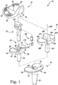
- the orthopaedic knee prosthesis system 10 includes a femoral component 12 configured to be coupled to a distal end of a patient's femur, a tibial tray 16 that is configured to be coupled to a proximal end of a patient's femur, and a pair of tibial inserts 18, 20 configured to be assembled separately with the tibial tray 16.
- the femoral component 12, the tibial tray 16, and the tibial insert 18 may be assembled to form one type of orthopaedic knee prosthesis; specifically, a rotating platform orthopaedic knee prosthesis.
- the femoral component 12, the tibial tray 16, the tibial insert 20, and a modular insert 22 may be separately assembled to form another type of orthopaedic knee prosthesis; specifically, a hinged orthopaedic knee prosthesis, as described below.
- the femoral component 12 includes a post 24 that is configured to be implanted into the distal end of the patient's femur.
- the post 24 is attached to a body 26 having a pair of spaced-apart lateral and medial condyles 28.
- the condyles 28 include respective lateral and medial condyle surfaces 30, 32, which are curved convexly.
- An intercondylar notch 34 is defined between the lateral and medial condyles 28 and is sized to receive the modular insert 22.
- the femoral component 12 and the tibial tray 16 are each formed from an implant grade metallic material such as, for example, cobalt chromium.
- the tibial tray 16 includes a base 36 and an anchor 38 that extends inferiorly from a distal surface 40 of the base 36.
- the base 36 is sized and shaped to conform to the configuration of a surgically-prepared proximal surface of the patient's tibia
- the anchor 38 is sized and shaped to be implanted into a surgically-prepared intramedullary canal of the patient's tibia.
- the base 36 includes a substantially planar proximal surface 42 that is positioned opposite the distal surface 40.
- a curved outer wall 44 extends between from the surfaces 40, 42 and is sized and shaped to conform to the outer edge of the surgically-prepared proximal surface of the patient's tibia.
- An opening 46 is defined in the proximal surface 42, and the tray 16 includes an aperture 48 that extends inwardly from the opening 46. The aperture 48 extends through the base 36 and into the anchor 38.
- the tibial tray 16 may be assembled with one of the tibial inserts 18, 20 shown in FIG. 1 to form a tibial component.
- Each of the inserts 18, 20 is formed from an implant grade plastic material such as, for example, ultra-high molecular weight polyethylene (UHMWPE).
- UHMWPE ultra-high molecular weight polyethylene
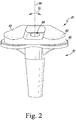
- the tibial insert 20 includes a platform 52 that is sized to be positioned on the proximal surface 42 of the tibial tray 16 and an elongated stem 54 that extends inferiorly from a distal surface 56 of the platform 52 along a longitudinal axis 58. Similar to the proximal surface 42 of the tibial tray 16, the distal surface 56 of the platform is substantially planar.
- the platform 52 also includes a pair of concave curved proximal surfaces 60, 62 that correspond to the lateral and medial condyle surfaces 30, 32 of the femoral component 12.
- the platform also includes a curved outer wall 64 extends between from the surfaces 56, 60, 62.
- an opening 66 is defined in the proximal surfaces 60, 62 of the platform 52.
- the tibial insert 18 also includes an aperture 68 that extends inwardly from the opening 66 through the platform 52 and into the elongated stem 54. The aperture 68 then extends along the longitudinal axis 58 of the stem 54 to a closed end (not shown).
- the distal surface 56 of the tibial insert 20 engages the proximal surface 42 of the tibial tray.
- the elongated stem 54 of the tibial insert 20 is sized to be received in the aperture 48 of the tibial tray 16 when the tibial insert is coupled to the tibial tray.
- the stem 54 is sized and shaped to permit the tibial insert 20 to rotate about the longitudinal axis 58 when positioned in the aperture 48 of the tibial tray, as indicated by the arrows 70 in FIG. 2 .
- the tibial tray 16 and the tibial insert 20 may be combined with the femoral component 12 and the modular insert 22 to form a hinged orthopaedic knee prosthesis.
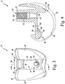
- the femoral component 12 includes an intercondylar notch 34 that is defined between the medial and lateral condyles 28.
- Each condyle 28 includes a sidewall 80 that extends distally from a respective condyle surface 30, 32 to a base wall 82.
- the intercondylar notch 34 has a width 84 that is defined between the sidewalls 80, which is sized to receive the proximal end of the modular insert 22, as described in greater detail below.
- the femoral component 12 also includes a posterior cam 90 that extends between the sidewalls 80 at a posterior end 92 of the intercondylar notch 34.
- the posterior cam 90 has a curved anterior surface 94.
- An opening 96 is defined in the anterior surface 94 adjacent to the base wall 82.
- a number of walls 98 extend inwardly from the opening 96 to define a groove 100 in the anterior surface 94.
- the groove 100 is sized to receive a retaining flange 102 of the modular insert 22 to couple the modular insert 22 to the femoral component 12.
- the femoral component 12 includes an anterior flange 104 that extends between the sidewalls 80 at an anterior end 106 of the intercondylar notch 34.
- An opening 110 is defined in the base wall 82 adjacent to the anterior flange 104.
- An inner wall 112 extends proximally from the opening 110 through the post 24 to an opening 114 defined in the proximal end of the post.
- the inner wall 112 and the openings 110, 114 define a passageway 116 extending through the post 24.
- the inner wall 112 includes a substantially smooth distal section 118 that is connected to a threaded proximal section 120.
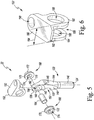
- the modular insert 22 includes an elongated stem 130 that is pivotally coupled to a bracket 132 sized to be positioned in the intercondylar notch 34 of the femoral component 12.
- the elongated stem 130 extends from a distal end 134 sized to be positioned in the aperture 68 of the tibial insert 20 to a proximal end 136 configured to be coupled to the bracket 132.
- the elongated stem 130 has a longitudinal axis 140 that is positioned to be coincident with the longitudinal axis 58 of the tibial insert 20 when the stem is positioned in the aperture 68.
- the elongated stem 130 has a spine 142 that extends distally from the proximal end 136 and is connected to a trunk 144 that extends proximally from the distal end 134.
- the trunk 144 has a cylindrical distal section 146 and a faceted proximal section 148.
- the proximal section 148 includes a concave curved posterior surface 150 that defines a notch 152 sized and shaped to receive the curved anterior surface 94 of the femoral component 12.
- the spine 142 of the elongated stem 130 has a medial opening (not shown), a lateral opening 156 that is positioned opposite the medial opening, and an inner wall 160 extending between the openings 156, 158.
- the inner wall 160 defines a cylindrical passageway 162 extending through the spine 142 that is sized to receive a hinge pin 164, as described in greater detail below.
- the modular insert 22 also includes a pair of bushings 166, 168 are sized and shaped to be positioned at either end of the passageway 162 of the spine 142.
- Each of the bushings 166, 168 includes an inner flange 170 configured to engage the sides of the spine 142 and a sleeve 172 extending outwardly from the flange 170.
- a passageway 174 extends through each bushing 166, 168, which is sized to receive an end of the hinge pin 164.
- the passageways 162, 174 and the hinge pin 164 cooperate to define a rotational axis 176 about which the femoral component 12 articulates when assembled with the modular insert 22.
- the modular insert 22 includes a bracket 132 sized to be positioned in the intercondylar notch 34 of the femoral component 12.
- the bracket 132 include a base plate 180 and a pair of arms 182, 184 that extends inferiorly from the base plate 180.
- the arms 182, 184 are spaced apart such that a channel 186 sized to receive the spine 142 of the elongated stem 130 is defined between the arms.
- Each of the arms 182, 184 also has a bore 188 that opens into the channel 186.
- the bores 188 are aligned and are sized to receive the sleeves 172 of the bushings 166, 168.
- the modular insert 22 includes a flange 102, which extends posteriorly from the base plate 180, and is sized to be received in the groove 100 of the femoral component 12.
- the modular insert 22 also includes a bore 190 that extends in an inferior-superior direction through the anterior end of the base plate 180. As described in greater detail in regard to FIGS. 7-8 , the bore 190 is sized to receive a fastener 192 that, along with the flange 102, is configured to couple the modular insert 22 to the femoral component 12.
- the bracket 132 is sized to be positioned in the intercondylar notch 34 of the femoral component 12.
- the bracket 132 has a medio-lateral width 194 that is defined between the sidewalls of the base plate 180.
- the medio-lateral width 194 is less than or equal to the width 84 of the intercondylar notch 34 to permit the bracket 132 to be inserted into the notch.
- hinge pin 164 extends a length that is equal to the medio-lateral width 194 so that it can also be inserted into the notch 34.
- the elongated stem 130, the bracket 132, and the hinge pin 164 are formed from an implant-grade metallic material such as, for example, cobalt chromium.
- the bushings 166, 168 are formed from an implant-grade plastic material such as, for example, ultra-high molecular weight polyethylene (UHMWPE). It should be appreciated that in other embodiments portions of, for example, the stem 130 or the bracket 132 may be formed from implant-grade plastic materials.
- UHMWPE ultra-high molecular weight polyethylene
- the fastener 192 includes a head 200 and an elongated shaft 202 that extends away from the head 200.
- the bracket 132 is also formed from an implant-grade metallic material such as, for example, cobalt chromium.
- the shaft 202 is illustratively cylindrical and includes a substantially smooth outer surface 204.
- the shaft 202 extends outwardly from the bore 190 defined in the bracket 132 and is sized to engage the smooth distal wall section 118 of the femoral component 12.
- the fastener 192 couples the bracket 132 (and hence the modular insert 22) to the femoral component 12 via a press-fit between the wall section 118 and the shaft 202. It should be appreciated that in other embodiments the section 118 and the shaft 202 may include corresponding threads to couple the component 12 to the insert 22.
- the modular insert 22 also includes a plug 210 configured to be coupled to the head 200 of the fastener 192.
- the plug 210 is illustrative formed from an elastomeric material such as, for example, rubber.
- the plug 210 includes a main body 212 and a pair of arms 214 that extend outwardly from the main body 212. As shown in FIG. 9 , each arm 214 includes a curved inner surface 216 that is shaped to engage the head 200 of the fastener 192.
- the inner surfaces 216 cooperate with a superior surface 218 of the main body 212 to form a slot 220 sized to receive and retain the head 200 of the fastener 192.
- the main body 212 is wedge-shaped and includes an anterior surface 222 that extends from the superior surface 218 to an inferior tip 224.
- a posterior surface 226 extending at an oblique angle relative to the anterior surface 222 extends from the superior surface 218 to the inferior tip 224.
- the posterior surface 226 is shaped to engage the anterior surface of the spine 142 of the modular insert 22 when the femoral component 12 is in extension.
- the tibial insert 18 includes a platform 252 that is sized to be positioned on the proximal surface 42 of the tibial tray 16 and an elongated stem 254 that extends inferiorly from a distal surface 256 of the platform 252 along a longitudinal axis 258.
- the distal surface 256 of the platform 252 is substantially planar.
- the platform 252 also includes a pair of concave curved proximal surfaces 260, 262 that correspond to the lateral and medial condyle surfaces 30, 32 of the femoral component 12.
- the platform 252 also includes a curved outer wall 264 extends between the surfaces 260, 262, 256.
- the tibial insert 18 also includes a spine 266 that extend superiorly from the platform 252 between the pair of concave curved proximal surfaces.
- the spine 266 includes a convex curved anterior surface 268 and a concave curved posterior surface 270.
- the concave curved posterior surface 270 is shaped to engage the convex curved anterior surface 94 of the posterior cam 90 of the femoral component 12.
- the distal surface 256 of the tibial insert 18 engages the proximal surface 42 of the tibial tray.
- the elongated stem 254 of the tibial insert 18 is sized to be received in the aperture 48 of the tibial tray 16 when the tibial insert 18 is coupled to the tibial tray 16.
- the stem is sized and shaped to permit the tibial insert 18 to rotate about the longitudinal axis 258 when positioned in the aperture 48 of the tibial tray 16.
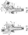
- a patient may initially have implanted, for example, a rotating platform orthopaedic prosthesis with the femoral component 12, the tibial tray 16, and tibial insert 20. Due to injury, bone loss, or other degradation of the patient's mobility, a surgeon may determine that the existing orthopaedic prosthesis may need to be replaced with a hinged orthopaedic prosthesis. To do so, the surgeon may open the patient's soft tissue in the region surrounding the knee joint.
- surgeon may then remove some or all of the components of the existing orthopaedic prosthesis, surgically-prepare the patient's bones to receive a new femoral component 12, tibial tray 16, tibial insert 20, and modular insert 22, and then implant those components in the patient's joint.
- the surgeon may choose to remove the tibial insert 18 and leave one or both of the existing femoral component 12 and the tibial tray 16 implanted in the patient's joint.
- the surgeon may perform a trial reduction to select a modular insert 22 and tibial insert 20 of appropriate size.
- the surgeon may align the elongated stem 54 of the insert 20 with the aperture 48 of the tibial tray 16 and advance the distal tip of the stem 54 into the aperture 48 to engage the platform 52 with the base 36 of the tray 16.
- the surgeon may align the trunk 144 of the modular insert 22 with the aperture 68 of the tibial insert 20 and advance the distal tip of the trunk 144 into the aperture 68 to seat the modular insert 22 on the tibial insert 20.
- the surgeon may advance the retaining flange 102 of the bracket 132 of the modular insert 22 into the groove 100 defined in the posterior cam 90 of the femoral component 12, as shown in FIG. 12 .
- the surgeon may also align the bore 190 with the passageway 116 of the femoral component 12 and advance the elongated shaft 202 of the fastener 192 through the bore 190 and into the passageway 116.
- the bracket 132 (and hence the modular insert 22) is coupled to the femoral component 12 via a press-fit between the wall section 118 defining the passageway 116 and the shaft 202.
- the surgeon may attach the plug 210 to the head 200 of the fastener 192 to form the hinged orthopaedic prosthesis shown in FIG. 12 .
- the plug 210 engages the anterior surface of the spine 142 of the modular insert 22, and the femoral condyles 28 engages the proximal surfaces 60, 62 of the tibial insert 20.
- the femoral component 12 is pivoted above the axis 176 extending through the hinge pin 164.
- the surface geometry of the femoral condyles causes the modular insert 22 to advance superiorly in the direction indicated by arrow 280 in FIG. 12 while the tibial insert 20 remains engaged with the tibial tray 16.
- the posterior cam 90 is positioned in the notch 152 defined in the modular insert 22 with its anterior surface 94 engaged with the posterior surface 150 of the modular insert 22, thereby preventing further flexion.
- the femoral component 12, tibial insert 20, and modular insert 22 are configured to pivot about the axis 58, which extends orthogonal to the hinge pin axis 176, during normal movement and use of the orthopaedic prosthesis.
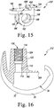
- the orthopaedic knee prosthesis 310 includes a femoral component 312 configured to be coupled to a distal end of a patient's femur, a tibial tray 16 that is configured to be coupled to a proximal end of a patient's femur, and a tibial insert 20 configured to be assembled with the tibial tray 16. It should be appreciated that the tibial insert and tibial tray of the prosthesis 310 are identical to the tibial insert and tibial tray described above in regard to FIGS.
- the prosthesis 310 also includes a modular insert 322 configured to couple the tibial insert 20 to the femoral component 312.
- the femoral component 312 is formed from an implant grade metallic material such as, for example, cobalt chromium. As shown in FIG. 16 , the femoral component 312 includes a post 324 that is configured to be implanted into the distal end of the patient's femur. The post 24 is attached to a body 326 having a pair of spaced-apart lateral and medial condyles 328. The condyles 328 include respective lateral and medial condyle surfaces 330, 332, which are curved convexly. An intercondylar notch 334 is defined between the lateral and medial condyles 28 and is sized to receive the modular insert 322.
- an implant grade metallic material such as, for example, cobalt chromium.
- Each condyle 328 includes a sidewall 380 that extends distally from a respective condyle surface 330, 332 to a base wall 382.
- the intercondylar notch 334 has a width that is defined between the sidewalls 380, which is sized to receive the proximal end of the modular insert 322, as described in greater detail below.
- the base wall 382 includes a posterior edge 384 that is sized to be received in a retaining groove 400 defined in the modular insert 322, also as described in greater detail below.
- An opening 110 is defined in the base wall 382, and an inner wall 112 extends proximally from the opening 110 through the post 324 to an opening 114 defined in the proximal end of the post.
- the inner wall 112 and the openings 110, 114 define a passageway 116 extending through the post 24.
- the inner wall 112 includes a substantially smooth distal section 118 that is connected to a threaded proximal section 120.
- the modular insert 322 includes an elongated stem 430 that is pivotally coupled to a bracket 432 sized to be positioned in the intercondylar notch 334 of the femoral component 312.
- the elongated stem 430 extends from a distal end 434 sized to be positioned in the aperture 68 of the tibial insert 20 to a proximal end 436 configured to be coupled to the bracket 432.
- the elongated stem 430 has a longitudinal axis 440 that is positioned to be coincident with the longitudinal axis 58 of the tibial insert 20 when the stem is positioned in the aperture 68.
- the elongated stem 430 has a spine 142 that extends distally from the proximal end 436 and is connected to a trunk 444 that extends proximally from the distal end 434.
- the trunk 444 has a cylindrical body, as shown in FIG. 14 .
- the spine 142 of the elongated stem 130 has a cylindrical passageway 162 (see FIG. 17 ) that is sized to receive a hinge pin 164.
- the modular insert 322 also includes a pair of bushings 166, 168 are sized and shaped to be positioned at either end of the passageway 162 of the spine 142.
- a passageway 174 extends through each bushing 166, 168, which is sized to receive an end of the hinge pin 164.
- the passageways 162, 174 and the hinge pin 164 cooperate to define a rotational axis 176 about which the femoral component 312 articulates when assembled with the modular insert 322.
- the modular insert 322 includes a bracket 432 sized to be positioned in the intercondylar notch 334 of the femoral component 312.
- the bracket 432 include a base plate 480 and a pair of arms 182, 184 that extends inferiorly from the base plate 480.
- the arms 182, 184 are spaced apart such that a channel 186 sized to receive the spine 142 of the elongated stem 430 is defined between the arms.
- Each of the arms 182, 184 also has a bore 188 that opens into the channel 186.
- the bores 188 are aligned and are sized to receive the sleeves 172 of the bushings 166, 168.
- the modular insert 322 includes a retaining groove 400, which is defined between the posterior end of the base plate 480 and a retaining flange 482 extending outwardly from the base plate 480.
- the flange 482 includes an arm 484 extending superiorly from the base plate 480, and another arm 486 extending anteriorly from the end of the arm 484.
- the arm 486 is spaced apart from the base plate 480 such that the groove 400 is defined between the arms 484, 486 and the base plate 480.
- the modular insert 322 also includes a bore 190 that extends in an inferior-superior direction through the anterior end of the base plate 180. As described above in regard to FIGS. 1-13 , the bore 190 is sized to receive a fastener 192 (see FIG. 14 ) that, along with the flange 102, is configured to couple the modular insert 322 to the femoral component 312.
- the bracket 432 is sized to be positioned in the intercondylar notch 334 of the femoral component 312.
- the bracket 432 has a medio-lateral width 194 that is defined between the sidewalls of the base plate 480.
- the medio-lateral width 194 is less than or equal to the width of the intercondylar notch 334 to permit the bracket 432 to be inserted into the notch.
- hinge pin 164 extends a length that is equal to the medio-lateral width 194 so that it can also be inserted into the notch 334.
- the surgeon may advance the retaining edge 384 of the femoral component 312 into the groove 400 of the bracket 432 to couple the modular insert 322 to the femoral component 312.
- the surgeon may also align the bore 190 with the passageway 116 of the femoral component 312 and advance the elongated shaft 202 of the fastener 192 through the bore 190 and into the passageway 116.
- the bracket 132 (and hence the modular insert 322) is coupled to the femoral component 312 via a press-fit between the wall section 118 defining the passageway 116 and the shaft 202.
- the surgeon may attach the plug 210 to the head 200 of the fastener 192 to form the hinged orthopaedic prosthesis shown in FIG. 17 .
- the plug 210 engages the anterior surface of the spine 142 of the modular insert 22, and the femoral condyles 28 engages the proximal surfaces 60, 62 of the tibial insert 20 (not shown in FIG. 17 ).
- an orthopaedic knee prosthesis 510 includes several similar components to the orthopaedic knee prosthesis system 10, which are referenced with the same reference numbers.
- the prosthesis 510 includes a modular insert 552 that is configured to be coupled the tibial insert 20 to a femoral component 554.
- the femoral component 554 may be the same as the femoral component 12.
- the femoral component 554 does not include a groove formed in an anterior surface of the posterior cam 556.
- the modular insert 552 includes an elongated stem 560 coupled to a bracket 562.
- the elongated stem 560 is configured to be inserted into the aperture 68 of the platform 52 of the tibial insert 20 and extend in an inferior-superior direction.
- the bracket 562 is hingedly attached to a spine 564 of the elongated stem 260.
- the bracket 562 includes bores (not shown) extending in a medial-lateral direction and configured to receive a hinge pin 164.
- the hinge pin 570 extends through an opening (not shown) in the spine 564 of the elongated stem 560.
- a pair of bushings 572 is positioned in the bores 566 so that the hinge pin 570 extends through openings 574 in the bushings 572.
- the bracket 562 pivots about the hinge pin 570 relative to the elongated stem 560.
- the bracket 562 includes a flange 580 extending from a posterior end 582 of the bracket 562.
- the flange 580 includes a posterior arm 584 extending from the posterior end 582 of the bracket 562.
- An arm 586 extends inferiorly from the posterior arm 584.
- the arms 584, 586 form a notch 590.
- the flange 580 is configured to couple to the posterior cam 556 of the femoral component 554 to at least partially secure the bracket 562 to the femoral component 554.
- a bore 600 extends through an anterior end 602 of the bracket 562.
- the bore 600 is configured to receive a fastener 610 that is extended into the passageway 116 in the post 24 of the femoral component 554.
- the fastener 610 extends transverse to the hinge pin 164.
- the fastener 610 is a threaded screw that is threaded into the bore 600 extending through the post 24.
- the fastener 610 is a captured screw that is captured in the bracket 662 and allowed to rotate so that the captured screw can be threaded into the passageway 116 extending through the post 24.
- a plug as described above, may be positioned on an end 612 of the fastener 610. The plug may be provided to limit extension of the prosthesis 510.
- exemplary embodiments of the present disclosure are described and illustrated below to encompass prosthetic knee joints and knee joint components, as well as methods of implanting and reconstructing knee joints. It will also be apparent to those of ordinary skill in the art that the preferred embodiments discussed below are exemplary in nature and may be reconfigured without departing from the scope and spirit of the present invention. However, for clarity and precision, the exemplary embodiments as discussed below may include optional steps, methods, and features that one of ordinary skill should recognize as not being a requisite to fall within the scope of the present invention.
Landscapes
- Health & Medical Sciences (AREA)
- Orthopedic Medicine & Surgery (AREA)
- Physical Education & Sports Medicine (AREA)
- Cardiology (AREA)
- Oral & Maxillofacial Surgery (AREA)
- Transplantation (AREA)
- Engineering & Computer Science (AREA)
- Biomedical Technology (AREA)
- Heart & Thoracic Surgery (AREA)
- Vascular Medicine (AREA)
- Life Sciences & Earth Sciences (AREA)
- Animal Behavior & Ethology (AREA)
- General Health & Medical Sciences (AREA)
- Public Health (AREA)
- Veterinary Medicine (AREA)
- Prostheses (AREA)
Applications Claiming Priority (1)
| Application Number | Priority Date | Filing Date | Title |
|---|---|---|---|
| US15/969,737 US10736748B2 (en) | 2018-05-02 | 2018-05-02 | Orthopaedic prosthetic system for a hinged-knee prosthesis |
Publications (3)
| Publication Number | Publication Date |
|---|---|
| EP3572049A2 true EP3572049A2 (de) | 2019-11-27 |
| EP3572049A3 EP3572049A3 (de) | 2020-02-12 |
| EP3572049B1 EP3572049B1 (de) | 2021-07-07 |
Family
ID=66290250
Family Applications (1)
| Application Number | Title | Priority Date | Filing Date |
|---|---|---|---|
| EP19171270.2A Active EP3572049B1 (de) | 2018-05-02 | 2019-04-26 | Orthopädisches prothesensystem für eine achsstielknieprothese |
Country Status (8)
| Country | Link |
|---|---|
| US (3) | US10736748B2 (de) |
| EP (1) | EP3572049B1 (de) |
| JP (2) | JP7408296B2 (de) |
| CN (1) | CN110433014B (de) |
| AU (1) | AU2019202948B2 (de) |
| BR (1) | BR102019008744A2 (de) |
| CA (1) | CA3041874A1 (de) |
| RU (1) | RU2019112077A (de) |
Families Citing this family (9)
| Publication number | Priority date | Publication date | Assignee | Title |
|---|---|---|---|---|
| USD744103S1 (en) * | 2011-12-29 | 2015-11-24 | Mako Surgical Corp. | Tibial baseplate |
| US10925743B2 (en) * | 2017-09-26 | 2021-02-23 | Stephen J. Incavo | Knee arthroplasty with modular femoral adapters |
| US10736748B2 (en) | 2018-05-02 | 2020-08-11 | Depuy Ireland Unlimited Company | Orthopaedic prosthetic system for a hinged-knee prosthesis |
| US11571309B2 (en) * | 2020-09-30 | 2023-02-07 | Depuy Ireland Unlimited Company | Orthopaedic surgical instrument system and a method of trialing an orthopaedic prosthetic assembly |
| US20230024863A1 (en) | 2021-07-23 | 2023-01-26 | Microport Orthopedics Holdings Inc. | Endoprosthetic rotating hinge knee assemblies, subassemblies, and methods |
| CN115778639A (zh) * | 2023-02-02 | 2023-03-14 | 骄英医疗器械(上海)有限公司 | 一种骨假体及其操作方法 |
| WO2025026774A1 (en) * | 2023-08-02 | 2025-02-06 | Waldemar Link Gmbh & Co. Kg | Prosthetic adapter device |
| US12385282B2 (en) * | 2023-09-07 | 2025-08-12 | Tony AWAD | Device to assist in closing doors, and biasing mechanism for same |
| WO2025052443A1 (en) * | 2023-09-08 | 2025-03-13 | Meril Healthcare Pvt. Ltd | Hinge knee joint prosthesis |
Family Cites Families (105)
| Publication number | Priority date | Publication date | Assignee | Title |
|---|---|---|---|---|
| GB1413477A (en) | 1972-01-05 | 1975-11-12 | Nat Res Dev | Bone joint prosthesis |
| US3852830A (en) | 1973-02-15 | 1974-12-10 | Richards Mfg Co | Knee prosthesis |
| GB1462876A (en) | 1973-05-17 | 1977-01-26 | Thackray C F Ltd | Knee arthroplasty |
| GB1509194A (en) | 1974-04-22 | 1978-05-04 | Nat Res Dev | Endoprosthetic devices |
| CA1045752A (en) | 1975-05-26 | 1979-01-09 | Robert W. Jackson | Prosthetic implant |
| US4219893A (en) | 1977-09-01 | 1980-09-02 | United States Surgical Corporation | Prosthetic knee joint |
| US4224697A (en) | 1978-09-08 | 1980-09-30 | Hexcel Corporation | Constrained prosthetic knee |
| US4215439A (en) | 1978-10-16 | 1980-08-05 | Zimmer, USA | Semi-restraining knee prosthesis |
| DE2901009A1 (de) | 1979-01-12 | 1980-07-17 | Link Waldemar Gmbh Co | Kniegelenk-endoprothese |
| US4340978A (en) | 1979-07-02 | 1982-07-27 | Biomedical Engineering Corp. | New Jersey meniscal bearing knee replacement |
| DE3343606A1 (de) | 1983-12-02 | 1985-07-04 | S + G Implants GmbH, 2400 Lübeck | Endoprothese fuer ein kniegelenk |
| DE3431645A1 (de) | 1984-08-29 | 1986-03-13 | GMT GESELLSCHAFT FüR MEDIZINISCHE TECHNIK MBH | Endoprothese |
| SE450336B (sv) | 1984-11-28 | 1987-06-22 | Branemark Per Ingvar | Ledprotes for permanent forankring i benvevnaden |
| FR2589720A1 (fr) | 1985-11-14 | 1987-05-15 | Aubaniac Jean | Ensemble prothetique pour l'articulation du genou |
| FR2590159A1 (fr) | 1985-11-15 | 1987-05-22 | Aubaniac Jean | Appareillage pour la mise en place de protheses du genou notamment mono-compartimentaires internes et/ou externes, trochleo-condyliennes internes ou externes |
| FR2601873B1 (fr) | 1986-07-25 | 1994-07-01 | Cuilleron J | Prothese totale intracondylienne du genou |
| FR2612767B1 (fr) | 1987-03-23 | 1994-01-21 | Letournel Emile | Prothese totale du genou |
| US4888021A (en) * | 1988-02-02 | 1989-12-19 | Joint Medical Products Corporation | Knee and patellar prosthesis |
| US5370701A (en) | 1990-09-28 | 1994-12-06 | Arch Development Corporation | Rotating/sliding contrained prosthetic knee |
| DE4038037B4 (de) | 1990-11-29 | 2010-06-02 | Waldemar Link Gmbh & Co. Kg | Kniegelenkendoprothese |
| US5824102A (en) | 1992-06-19 | 1998-10-20 | Buscayret; Christian | Total knee prosthesis |
| US5314481A (en) | 1992-11-12 | 1994-05-24 | Wright Medical Technology, Inc. | Hinged knee prosthesis with extended patellar track |
| GB9305279D0 (en) | 1993-03-15 | 1993-05-05 | Univ London | Total knee replacement prothesis |
| US5871541A (en) | 1993-11-23 | 1999-02-16 | Plus Endoprothetik, Ag | System for producing a knee-joint endoprosthesis |
| US6117175A (en) | 1994-08-22 | 2000-09-12 | Bosredon; Jean | Spherical knee joint prosthesis |
| US5824096A (en) | 1994-12-12 | 1998-10-20 | Biomedical Engineering Trust I | Hinged knee prosthesis with condylar bearing |
| DE59509363D1 (de) | 1995-01-31 | 2001-08-02 | Sulzer Orthopaedie Ag Baar | Gelenkprothese, insbesondere Kniegelenkprothese |
| RU2114580C1 (ru) | 1995-05-29 | 1998-07-10 | Открытое акционерное общество "Композит" | Эндопротез коленного сустава |
| DE19606462C1 (de) | 1996-02-21 | 1997-10-16 | Plus Endoprothetik Ag | Kniegelenkendoprothese |
| PT791344E (pt) * | 1996-02-21 | 2002-01-30 | Plus Endoprothetik Ag | Endoprotese de articulacao do joelho |
| US5766257A (en) | 1997-01-28 | 1998-06-16 | Implant Manufacturing And Testing Corporation | Artificial joint having natural load transfer |
| FR2760352B3 (fr) | 1997-03-10 | 1999-04-16 | Philippe Berret | Prothese totale du genou |
| US5951603A (en) | 1997-09-25 | 1999-09-14 | Johnson & Johnson Professional, Inc. | Rotatable joint prosthesis with axial securement |
| AT405903B (de) | 1997-12-19 | 1999-12-27 | Grafinger Josef | Gelenk (kniegelenk) |
| US6074424A (en) | 1998-01-23 | 2000-06-13 | Sulzer Orthopedics Inc. | Implantable knee joint prosthesis convertible from primary to revision |
| FR2776919B1 (fr) | 1998-04-02 | 2000-09-15 | Beguec Pierre Le | Prothese totale de genou a charniere |
| US6660039B1 (en) | 1998-05-20 | 2003-12-09 | Smith & Nephew, Inc. | Mobile bearing knee prosthesis |
| DE19823325C1 (de) | 1998-05-26 | 2000-03-23 | Werner Scholz | Kniegelenk-Endoprothesensystem |
| FR2787992B1 (fr) | 1999-01-04 | 2001-04-20 | Aesculap Sa | Prothese tibiale du genou a rotule a double inserts |
| JP4425404B2 (ja) | 1999-02-03 | 2010-03-03 | デピュイ・オーソピーディックス・インコーポレイテッド | 関節プロテーゼシステム |
| US6972039B2 (en) | 1999-03-01 | 2005-12-06 | Biomet, Inc. | Floating bearing knee joint prosthesis with a fixed tibial post |
| GB9914074D0 (en) | 1999-06-16 | 1999-08-18 | Btg Int Ltd | Tibial component |
| US6319283B1 (en) | 1999-07-02 | 2001-11-20 | Bristol-Myers Squibb Company | Tibial knee component with a mobile bearing |
| RU2145821C1 (ru) | 1999-08-10 | 2000-02-27 | Общество с ограниченной ответственностью Научно-производственное объединение "Остеомед" | Устройство для тотального эндопротезирования коленного сустава |
| GB9919954D0 (en) | 1999-08-23 | 1999-10-27 | Walker Peter S | Linked condylar total knee replacement |
| ES2221610T3 (es) | 1999-09-24 | 2005-01-01 | Centerpulse Orthopedics Ltd. | Pieza de tibia para una protesis de la articulacion de la rodilla, y kit con una pieza de tibia de este tipo. |
| ATE258773T1 (de) | 1999-11-09 | 2004-02-15 | Link Waldemar Gmbh Co | Knieprothesensystem |
| ATE440569T1 (de) | 1999-12-13 | 2009-09-15 | Zimmer Gmbh | Bausatz für eine kniegelenkprothese |
| FR2805454B1 (fr) | 2000-02-24 | 2003-01-10 | Aesculap Sa | Prothese du genou a cavite dans la trochlee |
| FR2805455B1 (fr) | 2000-02-24 | 2002-04-19 | Aesculap Sa | Composant femoral d'une prothese du genou a trois rayons de courbure |
| US6491726B2 (en) | 2000-03-08 | 2002-12-10 | Biomedical Engineering Trust I | Posterior stabilized prosthetic knee replacement with bearing translation and dislocation prevention features |
| US6475241B2 (en) | 2000-03-13 | 2002-11-05 | Biomedical Engineering Trust I | Posterior stabilized knee replacement with bearing translation for knees with retained collateral ligaments |
| US7247170B2 (en) | 2000-07-18 | 2007-07-24 | Biomet Manufacturing Corp. | Elbow prosthesis |
| US6613092B1 (en) | 2000-07-19 | 2003-09-02 | Centerpulse Orthopedics Inc. | Stem taper adapter |
| AU2001285488A1 (en) | 2000-08-28 | 2002-03-13 | Advanced Bio Surfaces, Inc | Method for mammalian joint resurfacing |
| US6485519B2 (en) | 2001-01-29 | 2002-11-26 | Bristol-Myers Squibb Company | Constrained prosthetic knee with rotating bearing |
| US6773461B2 (en) | 2001-01-29 | 2004-08-10 | Zimmer Technology, Inc. | Constrained prosthetic knee with rotating bearing |
| US20020120340A1 (en) | 2001-02-23 | 2002-08-29 | Metzger Robert G. | Knee joint prosthesis |
| US6797005B2 (en) | 2001-02-28 | 2004-09-28 | Biomedical Engineering Trust | Deep flexion posterior stabilized knee replacement with bearing translation |
| ES2278716T3 (es) | 2001-03-26 | 2007-08-16 | Zimmer Gmbh | Protesis de rodilla. |
| EP1252870A1 (de) | 2001-04-25 | 2002-10-30 | Waldemar Link (GmbH & Co.) | Knieprothese mit einem Beugescharnier |
| EP1252869A1 (de) | 2001-04-25 | 2002-10-30 | Waldemar Link (GmbH & Co.) | Knieprothese mit Rotationslager |
| US6482209B1 (en) | 2001-06-14 | 2002-11-19 | Gerard A. Engh | Apparatus and method for sculpting the surface of a joint |
| US6723102B2 (en) | 2001-06-14 | 2004-04-20 | Alexandria Research Technologies, Llc | Apparatus and method for minimally invasive total joint replacement |
| EP1269938A1 (de) | 2001-06-27 | 2003-01-02 | Waldemar Link (GmbH & Co.) | Gekoppelte Knieprothese mit Rotationslager |
| US20030009230A1 (en) | 2001-06-30 | 2003-01-09 | Gundlapalli Rama Rao V. | Surface sterilizable joint replacement prosthesis component with insert |
| JP2005514157A (ja) | 2001-12-21 | 2005-05-19 | スミス アンド ネフュー インコーポレーテッド | ヒンジ式関節システム |
| US7615081B2 (en) | 2002-05-24 | 2009-11-10 | Zimmer, Inc. | Femoral components for knee arthroplasty |
| US20040002767A1 (en) | 2002-06-28 | 2004-01-01 | Joseph Wyss | Modular knee joint prosthesis |
| US20040006393A1 (en) | 2002-07-03 | 2004-01-08 | Brian Burkinshaw | Implantable prosthetic knee for lateral compartment |
| EP1384454A1 (de) | 2002-07-26 | 2004-01-28 | WALDEMAR LINK GmbH & Co. KG | Knieprothese |
| US6827739B2 (en) | 2002-08-26 | 2004-12-07 | Zimmer Technology, Inc. | Easily assembled provisional orthopaedic implant |
| US20040054416A1 (en) | 2002-09-12 | 2004-03-18 | Joe Wyss | Posterior stabilized knee with varus-valgus constraint |
| US7309361B2 (en) | 2002-10-23 | 2007-12-18 | Wasielewski Ray C | Biologic modular tibial and femoral component augments for use with total knee arthroplasty |
| US6749638B1 (en) | 2002-11-22 | 2004-06-15 | Zimmer Technology, Inc. | Modular knee prosthesis |
| US20040102852A1 (en) | 2002-11-22 | 2004-05-27 | Johnson Erin M. | Modular knee prosthesis |
| CA2511216C (en) | 2002-12-20 | 2011-02-01 | Smith & Nephew, Inc. | High performance knee prostheses |
| WO2004069105A1 (en) | 2003-02-04 | 2004-08-19 | Zimmer Austin, Inc. | Rotating/non-rotating tibia plate/insert system |
| FR2854059B1 (fr) | 2003-04-24 | 2006-01-27 | Aesculap Sa | Plot modulaire pour prothese du genou postero-stabilisee |
| ATE461679T1 (de) | 2003-07-17 | 2010-04-15 | Exactech Inc | Bewegliche belastbare knieprothese |
| US7799085B2 (en) | 2003-11-18 | 2010-09-21 | Depuy Products, Inc. | Modular implant system with fully porous coated sleeve |
| JP4681931B2 (ja) | 2004-04-28 | 2011-05-11 | ビュッシェル−パパス.トラスト | 蝶番式人工膝関節 |
| DE102005022583B3 (de) | 2005-05-09 | 2007-02-01 | Aesculap Ag & Co. Kg | Knieendoprothese |
| GB0510194D0 (en) | 2005-05-19 | 2005-06-22 | Mcminn Derek J W | Knee prosthesis |
| EP1993483B1 (de) | 2006-03-13 | 2013-06-19 | Mako Surgical Corp. | Prothese sowie verfahren zum planen der implantation |
| US7658767B2 (en) * | 2006-06-30 | 2010-02-09 | Depuy Products, Inc. | Hinged orthopaedic prosthesis |
| US7842093B2 (en) | 2006-07-18 | 2010-11-30 | Biomet Manufacturing Corp. | Method and apparatus for a knee implant |
| US8163028B2 (en) | 2007-01-10 | 2012-04-24 | Biomet Manufacturing Corp. | Knee joint prosthesis system and method for implantation |
| US8328873B2 (en) | 2007-01-10 | 2012-12-11 | Biomet Manufacturing Corp. | Knee joint prosthesis system and method for implantation |
| US7993407B2 (en) | 2007-06-29 | 2011-08-09 | Depuy Products, Inc. | Orthopaedic prosthesis having a positionable stem |
| MY146046A (en) * | 2007-08-10 | 2012-06-15 | Sancheti Kantilal Hastimal | Knee joint prosthesis |
| US7918893B2 (en) * | 2007-09-30 | 2011-04-05 | Depuy Products, Inc. | Hinged orthopaedic prosthesis |
| CN102006839B (zh) | 2008-02-18 | 2014-07-23 | 麦克斯外科整形公司 | 全膝关节置换假体 |
| FR2932079B1 (fr) * | 2008-06-06 | 2010-07-30 | Michel Bercovy | Prothese totale de genou |
| US8236061B2 (en) * | 2008-06-30 | 2012-08-07 | Depuy Products, Inc. | Orthopaedic knee prosthesis having controlled condylar curvature |
| US9452052B2 (en) * | 2009-03-27 | 2016-09-27 | Smith And Nephew Orthopaedics Ag | Artificial knee joint |
| US8568485B2 (en) | 2009-08-11 | 2013-10-29 | Imds Corporation | Articulating trials for prosthetic implants |
| US8906105B2 (en) | 2009-08-11 | 2014-12-09 | Michael D. Ries | Systems and methods for mobile bearing prosthetic knee |
| EP2822509B1 (de) | 2012-03-06 | 2016-03-02 | University of Cape Town | Knieprothese mit drehscharnier |
| IN2014DE00549A (de) * | 2013-03-07 | 2015-06-12 | Depuy Ireland | |
| US9585758B2 (en) * | 2013-03-12 | 2017-03-07 | Biomet Manufacturing, Llc | Knee prosthesis systems and methods |
| DE102014106012B9 (de) * | 2014-04-29 | 2015-09-17 | Aesculap Ag | Kniegelenkendoprothese |
| US10925743B2 (en) * | 2017-09-26 | 2021-02-23 | Stephen J. Incavo | Knee arthroplasty with modular femoral adapters |
| US10736748B2 (en) | 2018-05-02 | 2020-08-11 | Depuy Ireland Unlimited Company | Orthopaedic prosthetic system for a hinged-knee prosthesis |
| US11376128B2 (en) | 2018-12-31 | 2022-07-05 | Depuy Ireland Unlimited Company | Acetabular orthopaedic prosthesis and method |
-
2018
- 2018-05-02 US US15/969,737 patent/US10736748B2/en active Active
-
2019
- 2019-04-22 RU RU2019112077A patent/RU2019112077A/ru unknown
- 2019-04-26 EP EP19171270.2A patent/EP3572049B1/de active Active
- 2019-04-26 JP JP2019085243A patent/JP7408296B2/ja active Active
- 2019-04-26 AU AU2019202948A patent/AU2019202948B2/en active Active
- 2019-04-30 CN CN201910359981.1A patent/CN110433014B/zh active Active
- 2019-04-30 BR BR102019008744-7A patent/BR102019008744A2/pt not_active Application Discontinuation
- 2019-05-01 CA CA3041874A patent/CA3041874A1/en active Pending
-
2020
- 2020-08-11 US US16/990,168 patent/US11833053B2/en active Active
-
2023
- 2023-12-05 US US18/529,335 patent/US20240108471A1/en active Pending
- 2023-12-15 JP JP2023211988A patent/JP7648110B2/ja active Active
Non-Patent Citations (1)
| Title |
|---|
| None |
Also Published As
| Publication number | Publication date |
|---|---|
| US20190336297A1 (en) | 2019-11-07 |
| US10736748B2 (en) | 2020-08-11 |
| US20240108471A1 (en) | 2024-04-04 |
| US20200368030A1 (en) | 2020-11-26 |
| JP7408296B2 (ja) | 2024-01-05 |
| AU2019202948A1 (en) | 2019-11-21 |
| EP3572049A3 (de) | 2020-02-12 |
| US11833053B2 (en) | 2023-12-05 |
| RU2019112077A (ru) | 2020-10-26 |
| CN110433014B (zh) | 2024-10-11 |
| JP2019193791A (ja) | 2019-11-07 |
| BR102019008744A2 (pt) | 2019-11-19 |
| CN110433014A (zh) | 2019-11-12 |
| JP2024015427A (ja) | 2024-02-01 |
| AU2019202948B2 (en) | 2025-01-02 |
| CA3041874A1 (en) | 2019-11-02 |
| EP3572049B1 (de) | 2021-07-07 |
| JP7648110B2 (ja) | 2025-03-18 |
Similar Documents
| Publication | Publication Date | Title |
|---|---|---|
| US20240108471A1 (en) | Orthopaedic prosthetic system for a hinged-knee prosthesis | |
| US11696834B2 (en) | Orthopaedic prosthetic system for a rotating hinged-knee prosthesis | |
| CN112220589A (zh) | 股骨试件部件和相关联的矫形外科使用方法 | |
| US11116641B2 (en) | Orthopaedic prosthetic system for a rotating hinged-knee prosthesis | |
| US20200345519A1 (en) | Orthopaedic surgical instrument system and a method of trialing an orthopaedic prosthetic assembly | |
| CA2924694C (en) | Reverse knee prosthesis | |
| EP3692951B1 (de) | Orthopädisches prothesensystem für eine knieprothese mit drehscharnier | |
| US12042391B2 (en) | Orthopaedic implant system with hinge | |
| EP3427698B1 (de) | System für ein orthopädisches gelenkersatzverfahren | |
| CN121398764A (zh) | 具有受控曲率的铰接式整形外科假体系统 |
Legal Events
| Date | Code | Title | Description |
|---|---|---|---|
| PUAI | Public reference made under article 153(3) epc to a published international application that has entered the european phase |
Free format text: ORIGINAL CODE: 0009012 |
|
| STAA | Information on the status of an ep patent application or granted ep patent |
Free format text: STATUS: THE APPLICATION HAS BEEN PUBLISHED |
|
| AK | Designated contracting states |
Kind code of ref document: A2 Designated state(s): AL AT BE BG CH CY CZ DE DK EE ES FI FR GB GR HR HU IE IS IT LI LT LU LV MC MK MT NL NO PL PT RO RS SE SI SK SM TR |
|
| AX | Request for extension of the european patent |
Extension state: BA ME |
|
| PUAL | Search report despatched |
Free format text: ORIGINAL CODE: 0009013 |
|
| AK | Designated contracting states |
Kind code of ref document: A3 Designated state(s): AL AT BE BG CH CY CZ DE DK EE ES FI FR GB GR HR HU IE IS IT LI LT LU LV MC MK MT NL NO PL PT RO RS SE SI SK SM TR |
|
| AX | Request for extension of the european patent |
Extension state: BA ME |
|
| RIC1 | Information provided on ipc code assigned before grant |
Ipc: A61F 2/38 20060101AFI20200107BHEP |
|
| STAA | Information on the status of an ep patent application or granted ep patent |
Free format text: STATUS: REQUEST FOR EXAMINATION WAS MADE |
|
| 17P | Request for examination filed |
Effective date: 20200812 |
|
| RBV | Designated contracting states (corrected) |
Designated state(s): AL AT BE BG CH CY CZ DE DK EE ES FI FR GB GR HR HU IE IS IT LI LT LU LV MC MK MT NL NO PL PT RO RS SE SI SK SM TR |
|
| GRAP | Despatch of communication of intention to grant a patent |
Free format text: ORIGINAL CODE: EPIDOSNIGR1 |
|
| STAA | Information on the status of an ep patent application or granted ep patent |
Free format text: STATUS: GRANT OF PATENT IS INTENDED |
|
| INTG | Intention to grant announced |
Effective date: 20210202 |
|
| RIN1 | Information on inventor provided before grant (corrected) |
Inventor name: HATHAWAY, TYLER S Inventor name: REEDER, NATHAN C |
|
| GRAS | Grant fee paid |
Free format text: ORIGINAL CODE: EPIDOSNIGR3 |
|
| GRAA | (expected) grant |
Free format text: ORIGINAL CODE: 0009210 |
|
| STAA | Information on the status of an ep patent application or granted ep patent |
Free format text: STATUS: THE PATENT HAS BEEN GRANTED |
|
| AK | Designated contracting states |
Kind code of ref document: B1 Designated state(s): AL AT BE BG CH CY CZ DE DK EE ES FI FR GB GR HR HU IE IS IT LI LT LU LV MC MK MT NL NO PL PT RO RS SE SI SK SM TR |
|
| REG | Reference to a national code |
Ref country code: GB Ref legal event code: FG4D |
|
| REG | Reference to a national code |
Ref country code: AT Ref legal event code: REF Ref document number: 1407844 Country of ref document: AT Kind code of ref document: T Effective date: 20210715 |
|
| REG | Reference to a national code |
Ref country code: DE Ref legal event code: R096 Ref document number: 602019005833 Country of ref document: DE |
|
| REG | Reference to a national code |
Ref country code: IE Ref legal event code: FG4D |
|
| REG | Reference to a national code |
Ref country code: LT Ref legal event code: MG9D |
|
| REG | Reference to a national code |
Ref country code: NL Ref legal event code: MP Effective date: 20210707 |
|
| REG | Reference to a national code |
Ref country code: AT Ref legal event code: MK05 Ref document number: 1407844 Country of ref document: AT Kind code of ref document: T Effective date: 20210707 |
|
| PG25 | Lapsed in a contracting state [announced via postgrant information from national office to epo] |
Ref country code: LT Free format text: LAPSE BECAUSE OF FAILURE TO SUBMIT A TRANSLATION OF THE DESCRIPTION OR TO PAY THE FEE WITHIN THE PRESCRIBED TIME-LIMIT Effective date: 20210707 Ref country code: BG Free format text: LAPSE BECAUSE OF FAILURE TO SUBMIT A TRANSLATION OF THE DESCRIPTION OR TO PAY THE FEE WITHIN THE PRESCRIBED TIME-LIMIT Effective date: 20211007 Ref country code: AT Free format text: LAPSE BECAUSE OF FAILURE TO SUBMIT A TRANSLATION OF THE DESCRIPTION OR TO PAY THE FEE WITHIN THE PRESCRIBED TIME-LIMIT Effective date: 20210707 Ref country code: HR Free format text: LAPSE BECAUSE OF FAILURE TO SUBMIT A TRANSLATION OF THE DESCRIPTION OR TO PAY THE FEE WITHIN THE PRESCRIBED TIME-LIMIT Effective date: 20210707 Ref country code: NO Free format text: LAPSE BECAUSE OF FAILURE TO SUBMIT A TRANSLATION OF THE DESCRIPTION OR TO PAY THE FEE WITHIN THE PRESCRIBED TIME-LIMIT Effective date: 20211007 Ref country code: NL Free format text: LAPSE BECAUSE OF FAILURE TO SUBMIT A TRANSLATION OF THE DESCRIPTION OR TO PAY THE FEE WITHIN THE PRESCRIBED TIME-LIMIT Effective date: 20210707 Ref country code: PT Free format text: LAPSE BECAUSE OF FAILURE TO SUBMIT A TRANSLATION OF THE DESCRIPTION OR TO PAY THE FEE WITHIN THE PRESCRIBED TIME-LIMIT Effective date: 20211108 Ref country code: ES Free format text: LAPSE BECAUSE OF FAILURE TO SUBMIT A TRANSLATION OF THE DESCRIPTION OR TO PAY THE FEE WITHIN THE PRESCRIBED TIME-LIMIT Effective date: 20210707 Ref country code: FI Free format text: LAPSE BECAUSE OF FAILURE TO SUBMIT A TRANSLATION OF THE DESCRIPTION OR TO PAY THE FEE WITHIN THE PRESCRIBED TIME-LIMIT Effective date: 20210707 Ref country code: SE Free format text: LAPSE BECAUSE OF FAILURE TO SUBMIT A TRANSLATION OF THE DESCRIPTION OR TO PAY THE FEE WITHIN THE PRESCRIBED TIME-LIMIT Effective date: 20210707 Ref country code: RS Free format text: LAPSE BECAUSE OF FAILURE TO SUBMIT A TRANSLATION OF THE DESCRIPTION OR TO PAY THE FEE WITHIN THE PRESCRIBED TIME-LIMIT Effective date: 20210707 |
|
| PG25 | Lapsed in a contracting state [announced via postgrant information from national office to epo] |
Ref country code: PL Free format text: LAPSE BECAUSE OF FAILURE TO SUBMIT A TRANSLATION OF THE DESCRIPTION OR TO PAY THE FEE WITHIN THE PRESCRIBED TIME-LIMIT Effective date: 20210707 Ref country code: LV Free format text: LAPSE BECAUSE OF FAILURE TO SUBMIT A TRANSLATION OF THE DESCRIPTION OR TO PAY THE FEE WITHIN THE PRESCRIBED TIME-LIMIT Effective date: 20210707 Ref country code: GR Free format text: LAPSE BECAUSE OF FAILURE TO SUBMIT A TRANSLATION OF THE DESCRIPTION OR TO PAY THE FEE WITHIN THE PRESCRIBED TIME-LIMIT Effective date: 20211008 |
|
| REG | Reference to a national code |
Ref country code: DE Ref legal event code: R097 Ref document number: 602019005833 Country of ref document: DE |
|
| PG25 | Lapsed in a contracting state [announced via postgrant information from national office to epo] |
Ref country code: DK Free format text: LAPSE BECAUSE OF FAILURE TO SUBMIT A TRANSLATION OF THE DESCRIPTION OR TO PAY THE FEE WITHIN THE PRESCRIBED TIME-LIMIT Effective date: 20210707 |
|
| PLBE | No opposition filed within time limit |
Free format text: ORIGINAL CODE: 0009261 |
|
| STAA | Information on the status of an ep patent application or granted ep patent |
Free format text: STATUS: NO OPPOSITION FILED WITHIN TIME LIMIT |
|
| PG25 | Lapsed in a contracting state [announced via postgrant information from national office to epo] |
Ref country code: SM Free format text: LAPSE BECAUSE OF FAILURE TO SUBMIT A TRANSLATION OF THE DESCRIPTION OR TO PAY THE FEE WITHIN THE PRESCRIBED TIME-LIMIT Effective date: 20210707 Ref country code: SK Free format text: LAPSE BECAUSE OF FAILURE TO SUBMIT A TRANSLATION OF THE DESCRIPTION OR TO PAY THE FEE WITHIN THE PRESCRIBED TIME-LIMIT Effective date: 20210707 Ref country code: RO Free format text: LAPSE BECAUSE OF FAILURE TO SUBMIT A TRANSLATION OF THE DESCRIPTION OR TO PAY THE FEE WITHIN THE PRESCRIBED TIME-LIMIT Effective date: 20210707 Ref country code: EE Free format text: LAPSE BECAUSE OF FAILURE TO SUBMIT A TRANSLATION OF THE DESCRIPTION OR TO PAY THE FEE WITHIN THE PRESCRIBED TIME-LIMIT Effective date: 20210707 Ref country code: CZ Free format text: LAPSE BECAUSE OF FAILURE TO SUBMIT A TRANSLATION OF THE DESCRIPTION OR TO PAY THE FEE WITHIN THE PRESCRIBED TIME-LIMIT Effective date: 20210707 Ref country code: AL Free format text: LAPSE BECAUSE OF FAILURE TO SUBMIT A TRANSLATION OF THE DESCRIPTION OR TO PAY THE FEE WITHIN THE PRESCRIBED TIME-LIMIT Effective date: 20210707 |
|
| PGFP | Annual fee paid to national office [announced via postgrant information from national office to epo] |
Ref country code: FR Payment date: 20220308 Year of fee payment: 4 |
|
| 26N | No opposition filed |
Effective date: 20220408 |
|
| REG | Reference to a national code |
Ref country code: BE Ref legal event code: MM Effective date: 20220430 |
|
| PG25 | Lapsed in a contracting state [announced via postgrant information from national office to epo] |
Ref country code: MC Free format text: LAPSE BECAUSE OF FAILURE TO SUBMIT A TRANSLATION OF THE DESCRIPTION OR TO PAY THE FEE WITHIN THE PRESCRIBED TIME-LIMIT Effective date: 20210707 Ref country code: LU Free format text: LAPSE BECAUSE OF NON-PAYMENT OF DUE FEES Effective date: 20220426 |
|
| PG25 | Lapsed in a contracting state [announced via postgrant information from national office to epo] |
Ref country code: BE Free format text: LAPSE BECAUSE OF NON-PAYMENT OF DUE FEES Effective date: 20220430 |
|
| PG25 | Lapsed in a contracting state [announced via postgrant information from national office to epo] |
Ref country code: FR Free format text: LAPSE BECAUSE OF NON-PAYMENT OF DUE FEES Effective date: 20230430 |
|
| PG25 | Lapsed in a contracting state [announced via postgrant information from national office to epo] |
Ref country code: HU Free format text: LAPSE BECAUSE OF FAILURE TO SUBMIT A TRANSLATION OF THE DESCRIPTION OR TO PAY THE FEE WITHIN THE PRESCRIBED TIME-LIMIT; INVALID AB INITIO Effective date: 20190426 |
|
| PG25 | Lapsed in a contracting state [announced via postgrant information from national office to epo] |
Ref country code: MK Free format text: LAPSE BECAUSE OF FAILURE TO SUBMIT A TRANSLATION OF THE DESCRIPTION OR TO PAY THE FEE WITHIN THE PRESCRIBED TIME-LIMIT Effective date: 20210707 Ref country code: CY Free format text: LAPSE BECAUSE OF FAILURE TO SUBMIT A TRANSLATION OF THE DESCRIPTION OR TO PAY THE FEE WITHIN THE PRESCRIBED TIME-LIMIT Effective date: 20210707 |
|
| PG25 | Lapsed in a contracting state [announced via postgrant information from national office to epo] |
Ref country code: MT Free format text: LAPSE BECAUSE OF FAILURE TO SUBMIT A TRANSLATION OF THE DESCRIPTION OR TO PAY THE FEE WITHIN THE PRESCRIBED TIME-LIMIT Effective date: 20210707 |
|
| PGFP | Annual fee paid to national office [announced via postgrant information from national office to epo] |
Ref country code: DE Payment date: 20250305 Year of fee payment: 7 |
|
| PGFP | Annual fee paid to national office [announced via postgrant information from national office to epo] |
Ref country code: CH Payment date: 20250501 Year of fee payment: 7 |
|
| PG25 | Lapsed in a contracting state [announced via postgrant information from national office to epo] |
Ref country code: TR Free format text: LAPSE BECAUSE OF FAILURE TO SUBMIT A TRANSLATION OF THE DESCRIPTION OR TO PAY THE FEE WITHIN THE PRESCRIBED TIME-LIMIT Effective date: 20210707 |
|
| PGFP | Annual fee paid to national office [announced via postgrant information from national office to epo] |
Ref country code: GB Payment date: 20260312 Year of fee payment: 8 |
|
| PGFP | Annual fee paid to national office [announced via postgrant information from national office to epo] |
Ref country code: IE Payment date: 20260310 Year of fee payment: 8 |
|
| PGFP | Annual fee paid to national office [announced via postgrant information from national office to epo] |
Ref country code: IT Payment date: 20260320 Year of fee payment: 8 |