EP3572041A1 - Intraokularlinse und verfahren zur herstellung davon - Google Patents
Intraokularlinse und verfahren zur herstellung davon Download PDFInfo
- Publication number
- EP3572041A1 EP3572041A1 EP18741500.5A EP18741500A EP3572041A1 EP 3572041 A1 EP3572041 A1 EP 3572041A1 EP 18741500 A EP18741500 A EP 18741500A EP 3572041 A1 EP3572041 A1 EP 3572041A1
- Authority
- EP
- European Patent Office
- Prior art keywords
- intraocular lens
- support portion
- optical
- main body
- elastic material
- Prior art date
- Legal status (The legal status is an assumption and is not a legal conclusion. Google has not performed a legal analysis and makes no representation as to the accuracy of the status listed.)
- Withdrawn
Links
Images





Classifications
-
- A—HUMAN NECESSITIES
- A61—MEDICAL OR VETERINARY SCIENCE; HYGIENE
- A61F—FILTERS IMPLANTABLE INTO BLOOD VESSELS; PROSTHESES; DEVICES PROVIDING PATENCY TO, OR PREVENTING COLLAPSING OF, TUBULAR STRUCTURES OF THE BODY, e.g. STENTS; ORTHOPAEDIC, NURSING OR CONTRACEPTIVE DEVICES; FOMENTATION; TREATMENT OR PROTECTION OF EYES OR EARS; BANDAGES, DRESSINGS OR ABSORBENT PADS; FIRST-AID KITS
- A61F2/00—Filters implantable into blood vessels; Prostheses, i.e. artificial substitutes or replacements for parts of the body; Appliances for connecting them with the body; Devices providing patency to, or preventing collapsing of, tubular structures of the body, e.g. stents
- A61F2/02—Prostheses implantable into the body
- A61F2/14—Eye parts, e.g. lenses or corneal implants; Artificial eyes
- A61F2/16—Intraocular lenses
- A61F2/1613—Intraocular lenses having special lens configurations, e.g. multipart lenses; having particular optical properties, e.g. pseudo-accommodative lenses, lenses having aberration corrections, diffractive lenses, lenses for variably absorbing electromagnetic radiation, lenses having variable focus
-
- A—HUMAN NECESSITIES
- A61—MEDICAL OR VETERINARY SCIENCE; HYGIENE
- A61L—METHODS OR APPARATUS FOR STERILISING MATERIALS OR OBJECTS IN GENERAL; DISINFECTION, STERILISATION OR DEODORISATION OF AIR; CHEMICAL ASPECTS OF BANDAGES, DRESSINGS, ABSORBENT PADS OR SURGICAL ARTICLES; MATERIALS FOR BANDAGES, DRESSINGS, ABSORBENT PADS OR SURGICAL ARTICLES
- A61L27/00—Materials for grafts or prostheses or for coating grafts or prostheses
- A61L27/14—Macromolecular materials
-
- A—HUMAN NECESSITIES
- A61—MEDICAL OR VETERINARY SCIENCE; HYGIENE
- A61F—FILTERS IMPLANTABLE INTO BLOOD VESSELS; PROSTHESES; DEVICES PROVIDING PATENCY TO, OR PREVENTING COLLAPSING OF, TUBULAR STRUCTURES OF THE BODY, e.g. STENTS; ORTHOPAEDIC, NURSING OR CONTRACEPTIVE DEVICES; FOMENTATION; TREATMENT OR PROTECTION OF EYES OR EARS; BANDAGES, DRESSINGS OR ABSORBENT PADS; FIRST-AID KITS
- A61F2/00—Filters implantable into blood vessels; Prostheses, i.e. artificial substitutes or replacements for parts of the body; Appliances for connecting them with the body; Devices providing patency to, or preventing collapsing of, tubular structures of the body, e.g. stents
- A61F2/02—Prostheses implantable into the body
- A61F2/14—Eye parts, e.g. lenses or corneal implants; Artificial eyes
- A61F2/16—Intraocular lenses
- A61F2002/1681—Intraocular lenses having supporting structure for lens, e.g. haptics
-
- A—HUMAN NECESSITIES
- A61—MEDICAL OR VETERINARY SCIENCE; HYGIENE
- A61F—FILTERS IMPLANTABLE INTO BLOOD VESSELS; PROSTHESES; DEVICES PROVIDING PATENCY TO, OR PREVENTING COLLAPSING OF, TUBULAR STRUCTURES OF THE BODY, e.g. STENTS; ORTHOPAEDIC, NURSING OR CONTRACEPTIVE DEVICES; FOMENTATION; TREATMENT OR PROTECTION OF EYES OR EARS; BANDAGES, DRESSINGS OR ABSORBENT PADS; FIRST-AID KITS
- A61F2/00—Filters implantable into blood vessels; Prostheses, i.e. artificial substitutes or replacements for parts of the body; Appliances for connecting them with the body; Devices providing patency to, or preventing collapsing of, tubular structures of the body, e.g. stents
- A61F2/02—Prostheses implantable into the body
- A61F2/14—Eye parts, e.g. lenses or corneal implants; Artificial eyes
- A61F2/16—Intraocular lenses
- A61F2002/1681—Intraocular lenses having supporting structure for lens, e.g. haptics
- A61F2002/1683—Intraocular lenses having supporting structure for lens, e.g. haptics having filiform haptics
-
- A—HUMAN NECESSITIES
- A61—MEDICAL OR VETERINARY SCIENCE; HYGIENE
- A61L—METHODS OR APPARATUS FOR STERILISING MATERIALS OR OBJECTS IN GENERAL; DISINFECTION, STERILISATION OR DEODORISATION OF AIR; CHEMICAL ASPECTS OF BANDAGES, DRESSINGS, ABSORBENT PADS OR SURGICAL ARTICLES; MATERIALS FOR BANDAGES, DRESSINGS, ABSORBENT PADS OR SURGICAL ARTICLES
- A61L2430/00—Materials or treatment for tissue regeneration
- A61L2430/16—Materials or treatment for tissue regeneration for reconstruction of eye parts, e.g. intraocular lens, cornea
Definitions
- the present invention relates to an intraocular lens used for the treatment of a cataract and a method of manufacturing the same.
- a method of inserting an artificial crystalline lens, a so-called intraocular lens, into the crystalline capsule is generally provided.
- the intraocular lens is often made of a foldable acrylic flexible material, and the intraocular lens can be folded and inserted from an incision provided in the cornea or the sclera.
- the toric intraocular lens capable of reducing astigmatism is also put to practical use.
- the toric intraocular lens is an intraocular lens having a cylindrical refractive power equivalent to that of corneal astigmatism.
- the toric intraocular lens is required to be inserted with the cylindrical axis of the lens aligned with the astigmatism axis of the cornea, and have a structure that does not cause positional deviation even after surgery.
- intraocular lens in accordance with the case of the patient's eye, they are basically constituted by an optical portion that compensates for refractive power and a support portion configured to fix the intraocular lens in the eye.
- An intraocular lens in which an optical portion and a support portion are integrated is referred to as a one-piece intraocular lens, and an intraocular lens in which a support portion of a material different from that of the optical portion is attached is referred to as a multi-piece intraocular lens.
- Patent Literature 1 There has been offered a technique of providing an intraocular lens that is as versatile as possible so as not to be susceptible to individual differences among patients (Patent Literature 1). In addition, there has been also offered a technique of reducing the burden on tissues in the patient's eye as much as possible (Patent Literatures 2 and 3).
- the technique of the present disclosure has been made in view of the above-described circumstances, and an object thereof is to provide an intraocular lens whose application range is wider than the application range of the conventional single intraocular lens from the viewpoint of the characteristic at the time of bending of the support portion.
- the intraocular lens of the present disclosure includes an optical portion having a predetermined refractive power, and a support portion configured to maintain a position of the optical portion in the eye, wherein the support portion includes a main body formed of a flexible material and a shaft portion formed of an elastic material, wherein at least a portion of the shaft portion is covered by the main body, and wherein an end of the shaft portion is provided away from the optical portion.
- the support portion of the intraocular lens thus obtained is more elastic than the support portion of the conventional one-piece intraocular lens, and more flexible than the support portion of the conventional multi-piece intraocular lens, so that it is possible to make an intraocular lens whose application range to the eye of a patient is wider than the application range of any one of the conventional one-piece intraocular lens and multi-piece intraocular lens.
- a moment of inertia of area of the main body may be a moment of inertia of area such that a restoration speed when the support portion returns to a natural state at a time of bending is a restoration speed between a restoration speed when a support portion formed only of the flexible material returns to a natural state at a time of bending and a restoration speed when a support portion formed only of the elastic material returns to a natural state at a time of bending.
- the shaft portion may extend to the distal end of the support portion and the joint portion. A region where the shaft portion extends includes a region of the support portion that is most bent at a time of bending.
- a thickness of a portion of the main body in an optical axis direction of the optical portion, the portion covering the shaft portion may be a thickness such that a restoration speed when the support portion returns to a natural state at a time of bending is a restoration speed between a restoration speed when a support portion formed only of the flexible material returns to a natural state at a time of bending and a restoration speed when a support portion formed only of the elastic material returns to a natural state at a time of bending.
- the intraocular lens includes an optical portion having a predetermined refractive power and a support portion configured to maintain a position of the optical portion in the eye.
- the method includes forming the support portion including a main body formed of a flexible material and a shaft portion formed of an elastic material, covering at least a portion of the shaft portion by the main body, and providing an end of the shaft portion away from the optical portion.
- a monomer of the flexible material may be polymerized to form a guide configured to position the elastic material, and after the elastic material is positioned by the guide, a monomer of the flexible material may be polymerized to form the main body.
- the elastic material may be placed on a cross-link portion of a mold having the cross-link portion configured to cross-link the elastic material.
- a monomer of the flexible material may be polymerized to form the main body.
- alignment may be performed such that the elastic material is included in the support portion and the polymerized monomer of the flexible material may be cut out.
- an intraocular lens whose application range is wider than that of the conventional single intraocular lens from the viewpoint of the characteristics at the time of bending of the support portion may be made.
- intraocular lenses There are various types of intraocular lenses according to the case of a patient's eye, and can be roughly classified into two types of intraocular lenses: a one-piece intraocular lens and a multi-piece intraocular lens.
- An intraocular lens in which an optical portion and a support portion are integrated is referred to as a one-piece intraocular lens
- an intraocular lens in which a support portion of a material different from that of the optical portion is attached is referred to as a multi-piece intraocular lens.
- the one-piece intraocular lens has the following advantages and disadvantages as compared with the multi-piece intraocular lens since it has the integrated optical portion and support portion.
- multi-piece intraocular lens has the following advantages and disadvantages as compared to one-piece intraocular lens.
- the multi-piece intraocular lens refers to an intraocular lens in which two support portions are connected to one optical portion.
- the one-piece intraocular lens and the multi-piece intraocular lens each have advantages and disadvantages.
- the one-piece intraocular lens is used, and when the stability of the intraocular lens in the eye is required, or when the condition of the crystalline capsule is concerned from the viewpoint of the above-mentioned disadvantages, the multi-piece intraocular lens is used. In this way, it is necessary to select the intraocular lens depending on the condition of the patient's eye or the situation of the surgery.
- an intraocular lens having both the advantages of the one-piece intraocular lens and the advantages of the multi-piece intraocular lens, that is, having high elasticity and flexibility is provided.
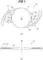
- Fig. 1 is a schematic view showing an example of an intraocular lens 10 in the present embodiment.
- Fig. 1(a) is a view of the intraocular lens 1 when viewed in a direction parallel to the optical axis AX of an optical portion 11
- Fig. 1(b) is a view of the intraocular lens 1 when viewed in a direction perpendicular to the optical axis AX of the optical portion 11.
- the intraocular lens 10 includes the optical portion 11 having a predetermined refractive power and two long flat plate-like support portions 12 configured to hold the optical portion 11 in the eye. Furthermore, the support portion 12 includes a main body 121 connected integrally with the optical portion 11. The support portion 12 also includes a shaft portion 122 covered by the main body 121. The optical portion 11 and the support portion 12 are connected to each other via a joint portion 13. The shaft portion 122 extends to the distal end of the support portion 12 and the joint portion 13. A region where the shaft portion 122 extends includes a region of the support portion 12 that is most bent when the support portion 12 is bent by receiving a compressive load such as coming into contact with the crystalline capsule.
- a region 14 that is most bent when the support portion 12 is bent under a compressive load is indicated by a dotted circle.
- the external force applied to the support portion 12 is not local, but the well-rounded force is applied concentrically around the force point. From this point of view, it can be said that in the support portion 12, the region that is most bent before the external force is applied is the most flexible region. It is also probable that the region which is the most flexible in the support portion 12 be a region where the cross-sectional area of the flexible material (details are mentioned later) constituting the support portion 12 is the smallest.
- a flexible material is used as a material of the optical portion 11 and the main body 121 of the support portion 12.
- the flexible material refers to a material that is highly flexible and is not easily restored even when deformed.
- the flexible material includes a hydrophobic acrylic material, a hydrophilic acrylic material, or a silicone material.
- an elastic material is used as a material of the shaft portion 122.
- the elastic material refers to a material that is easily deformed but has a large repulsive force generated at the time of deformation and a high shape memory.
- the elastic material includes a polyvinylidene fluoride (PVDF) material, a rubber material, or a polyimide material.
- PVDF polyvinylidene fluoride
- the end 123 of the shaft portion 122 is provided away from the optical portion 11.
- the shaft portion 122 may be provided not to extend to the peripheral portion of the optical portion 11, that is, to the joint portion 13, which is a connection portion between the optical portion 11 and the support portion 12, or part of the shaft portion 122 may be provided to extend to the joint portion 13.
- the thickness of the joint portion (corresponding to the joint portion 13 in the present embodiment) of the optical portion and the support portion is required to be secured, that is, it is necessary to secure a large cross-sectional area as viewed from the optical axis AX direction.
- the intraocular lens 10 in the present embodiment since it is not necessary to connect the shaft portion 122 to the optical portion 11, the joint portion 13 has only to have a thickness sufficient to ensure the connection between the optical portion 11 and the main body 121. Therefore, the intraocular lens 10 in the present embodiment can have a joint portion thinner than the joint portion of the conventional multi-piece intraocular lens. Thereby, it can be said that the intraocular lens 10 can be inserted into a small incision as compared with the conventional multi-piece intraocular lens.
- the intraocular lens In order to fix the intraocular lens in the eye, it is necessary for the intraocular lens to have sufficient force to push the ocular tissue. Since the intraocular lens cannot move autonomously, the intraocular lens is fixed in the eye using the force generated by receiving an external force, that is, the repulsive force of the support portion which is the elastic force of the support portion generated when the support portion bends or the stress at the time of compression of the support portion.
- Fig. 2 schematically shows the force generated when the intraocular lens 10 is fixed in the eye.
- the support portion 12 of the intraocular lens 10 comes into contact with the ocular tissue (such as a crystalline capsule) in a bent state.
- a compressive load is applied to the support portion 12 from the ocular tissue.
- the support portion 12 is subjected to a stress against a compressive load and an elastic force is generated by bending. Then, these stress and elastic force are generated as a repulsive force of the support portion 12 against the ocular tissue from the support portion 12.
- the support portion 12 of the intraocular lens 10 protrudes toward the cornea relative to the optical portion 11 in the eye.
- the intraocular lens 10 is an intraocular lens that can be easily fixed in the eye depends on the magnitude of the elastic force and stress at the time of compression of the support portion 12.
- the magnitude of the elastic force and stress at the time of compression of the support portion is larger in the multi-piece intraocular lens than in the one-piece intraocular lens.
- the intraocular lens 10 of the present embodiment since the support portion 12 is configured to have the main body 121 and the shaft portion 122, the stress of the support portion 12 at the time of compression is larger than the stress of the support portion at the time of compression when the support portion 12 is constituted by only the main body 121, and smaller than the stress of the support portion at the time of compression when the support portion 12 is constituted by only the shaft portion 122 and the shaft portion 122 is directly connected to the optical portion. That is, the intraocular lens 10 of the present embodiment can have a stress larger than the stress at the time of compression by the support portion of the conventional one-piece intraocular lens, and smaller than the stress at the time of compression by the support portion of the conventional multi-piece intraocular lens.
- Fig. 3 shows an example of the graph in which the compressive loads at the time of compression are compared between the support portion 12 of a sample obtained by manufacturing the intraocular lens 10 in which the support portion 12 has the main body 121 and the shaft portion 122 as described above, a support portion of a sample of the conventional one-piece intraocular lens, and a support portion of a sample of the conventional multi-piece intraocular lens.
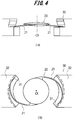
- Figs. 4 (a) and 4 (b) schematically show an example of a measurement method used to create the graph of Fig. 3 . In this embodiment, the measurement is performed based on the compressive load test of ISO11979-3.
- the two support portions 21 of an intraocular lens 20 are brought into contact with a measuring device 30, and the intraocular lens 20 is positioned with respect to the measuring device 30.
- the measuring device 30 has an arc-shaped surface 31 which simulates a general crystalline capsule in the eye, and part of the support portion 21 of the intraocular lens 20 comes into contact with the surface 31.
- a main body 32 of the measuring device 30 can be moved in the direction perpendicular to the optical axis CX of the intraocular lens 20. By moving the main body 32, a compressive load according to the displacement of the main body 32 is applied to the support portion 21 from the surface 31.
- the main body 32 is connected to, for example, a load cell or the like, and it is possible to measure the stress from the support portion 21 caused by the deformation of the support portion 21 according to the displacement of the main body 32.
- the graph illustrated in Fig. 3 is obtained from the measured stress.
- the repulsive force generated when the support portion receives an external force is referred to as a compressive load.
- the numbers on the horizontal axis indicate the Sample Nos.
- Sample Nos. A1 to A5 indicate samples having the shaft portion 122 according to the present embodiment.
- Sample Nos. C1 to C3 indicate samples manufactured by the same method and not having the shaft portion 122.
- Sample No. "1P” indicates a sample of the conventional one-piece intraocular lens.
- Sample No. "3P” indicates a sample of the conventional multi-piece intraocular lens.
- the vertical axis represents the measured value (mN) of the compressive load.
- the intraocular lens of the present embodiment can be inserted into an incision with a size equivalent to a size when the conventional one-piece intraocular lens is inserted.
- the support portion 12 of the samples of the intraocular lens 10 in the present embodiment whose Sample Nos. are A1 to A5 has a numerical value of the compressive load larger than that of the support portion of the conventional one-piece intraocular lens (Sample No "1P"). Further, the support portion 12 according to the samples having the Sample Nos. A1 to A5 has a numerical value of the compressive load smaller than that of the support portion of the conventional multi-piece intraocular lens. That is, the compressive load of the support portion 12 of the intraocular lens 10 of the present embodiment is between a compressive load of the support portion of the conventional one-piece intraocular lens and a compressive load of the support portion of the conventional multi-piece intraocular lens.
- the intraocular lens having the shaft portion in the present embodiment has an outer shape same as that of the conventional one-piece intraocular lens, the compressive load is large and it is probable that the fixation in the eye be improved. Furthermore, the disadvantage in that the lens is too elastic to handle as in the conventional multi-piece intraocular lens is improved.
- the main body 121 when viewed from the viewpoint of the moment of inertia of area of the flexible material forming the main body 121 of the support portion 12, it can be said that the main body 121 is formed to have the sufficient moment of inertia of area as compared with the support portion of the conventional one-piece intraocular lens.
- the moment of inertia of area is a quantity that represents the inflexibility of deformation with respect to bending moment in a member such as a so-called beam member. As the cross section of the member changes, the value of the moment of inertia of area also changes.
- the samples C1 to C3, which are manufactured by the same manufacturing method have a compressive load equivalent to that of the conventional one-piece intraocular lens, and if there is no shaft portion even when the manufacturing method of the present embodiment is used, an intraocular lens similar to the conventional one-piece intraocular lens can be made.
- the restoration speed of the support portion of each sample of the intraocular lens in the present embodiment was a speed at which the problem with the operation of the operator during the surgery would not occur. Moreover, the phenomenon in which the support portion of each sample of the intraocular lens in this embodiment was not restored to a natural state was not confirmed. It is probable that the stability of the intraocular lens in the eye in the present embodiment be higher than that of the conventional one-piece intraocular lens, considering that there is a possibility that restoration to the natural state may not occur due to the stickiness of the support portion in the conventional one-piece intraocular lens.
- the volume of the entire intraocular lens in each sample of the intraocular lens in the present embodiment is equivalent to that of the conventional one-piece intraocular lens, it is probable that the insertion device for the conventional one-piece intraocular lens may be used for the intraocular lens in the present embodiment.
- a method of manufacturing the intraocular lens 10 in the present embodiment will be described with reference to Figs. 5(a) to 5(c) .
- this manufacturing method two transparent flat glass plates, a shim ring (thickness: 0.1 mm to 0.3 mm), a material described above as an elastic material, a resin mold used for manufacturing the conventional one-piece intraocular lens, and a monomer made of the material described above as a flexible material are used.
- a shim ring is placed on a sheet of flat glass, and an elastic body is placed in the opening of the shim ring.
- the thickness of the shim ring is preferably larger than the thickness of the elastic material and not more than two thirds of the thickness of the support portion when the manufacture of the intraocular lens is completed.
- the shim ring may be formed of a magnetic body.
- a monomer of a flexible material is poured into the opening of the shim ring, and another flat glass is placed on the shim ring so that the two flat glasses sandwich the shim ring. At this time, the placement is performed so as not to generate bubbles in the monomer. Also, the elastic material is prevented from coming into contact with the shim ring.
- a shim ring is formed of a magnetic body, a shim ring can also be moved and aligned by using a magnet from on flat glass.
- Fig. 5(a) shows an example of the state of each member described above when polymerizing the monomer.
- a shim ring 200, a monomer 300 of a flexible material, and a shaft portion 400 formed of an elastic material are sandwiched between two flat glasses 100 and 110.
- the shaft portion 400 formed of the elastic material is the shaft portion 122 of the support portion 12 when the manufacture of an intraocular lens is completed.
- sandwiching and fixing the two flat glasses 100 and 110 by using magnets polymerization of the monomer can be performed more reliably.
- the sheet of polymerized monomer containing the shaft portion is cut into a suitable shape.
- a sheet 410 including the shaft portion 400 is cut out in the shape shown by the dotted line from the monomer 300 which has been polymerized.
- the sheet 410 which has been cut out is placed in the lower mold of the resin mold.
- the sheet 410 is placed on the region.
- the sheet 410 is placed so that the exposed surface of the support portion is directed upward.
- the entire elastic material can be covered with the flexible material by pouring the monomer of the flexible material in the next step.
- the sheet 410 may be placed upside down, and, in this case, a portion of the elastic material wherein the portion is not covered with the flexible material is directed downward, so that even when the monomer of the flexible material is poured in the next step, the portion of the elastic material remains not covered with the flexible material. Whether a portion of the elastic material with respect to the sheet 410 wherein the portion is not covered with the flexible material is directed upward or downward may be determined as appropriate.
- Fig. 5(c) shows an example of a state in which the sheets 410 and 411 including the elastic materials 400 and 401 are placed in a resin mold 500.
- the elastic material 401 and the sheet 411 are manufactured in the same manner as the elastic material 400 and the sheet 410.
- the sheet 410 including the elastic material 400 is placed so as to sandwich a preparation region 510 of the optical portion of the intraocular lens.
- a protrusion or a bank may be provided in a portion which does not constitute the intraocular lens.
- a mark serving as a mark may be provided, for example, on a resin mold flange region so that the processing position can be distinguished when processing the outer shape of the intraocular lens.
- the monomer of the flexible material is poured into the inside of the resin mold, and covered with the upper mold of the resin mold and sealed. At this time, the placement is performed so as not to generate bubbles in the monomer. Further, the position of the sheet of the elastic material placed above is prevented from being pushed by the monomer and shifted. Then, the lens is stored under a temperature environment where the monomer of the flexible material is polymerized to complete the polymerization.
- the intraocular lens is cut out from the resin mold according to the shape of the intraocular lens. At this time, alignment is performed so that the elastic material is included in the support portion. This alignment can be performed more easily if the above alignment mark is on the resin mold.
- the intraocular lens thus cut out is subjected to a process which is the same as the process of producing the conventional one-piece intraocular lens to complete the intraocular lens of the present embodiment.
- the resin mold (upper mold, lower mold) prepared to manufacture the intraocular lens of the present embodiment, the above-described material as an elastic material, and the monomer made of the material described above as a flexible material are used. Furthermore, the lower mold of the resin mold is provided with a mark for alignment of each material. Further, the upper mold of the resin mold is provided with a guide configured to position the elastic material forming the support portion.
- a guide configured to position the elastic material is formed by polymerizing the monomer of the flexible material.
- a mold is formed to polymerize the monomer poured into the lower mold into the shape of the guide.
- the shape of the guide is such that it is easy to polymerize the monomer of the flexible material to be performed later, and it is possible to restrict the position of the elastic body.
- the guide is provided in the preparation region of the support portion in the lower mold. Further, the height of the guide from the mounting surface is set to be higher than the thickness of the elastic material and lower than the thickness of the main body of the intraocular lens to be manufactured.
- a guide is formed so that the thickness of the polymerized flexible material is, for example, 0.1 mm or more.
- a flexible material may exist in the preparation region of the optical portion in a lower mold. This is because the monomer polymerized for the guide also has the transparency of the finally obtained optical portion by mirror-finishing the surface of another upper mold that covers the monomers in the subsequent polymerization of the monomer of the flexible material.
- the upper mold where the mold of the guide is formed is superimposed on the lower mold of the resin mold, and when polymerization of the monomer is completed and the guide is formed, the upper mold is removed from the lower mold, and the elastic body is placed on the lower mold using the guide.
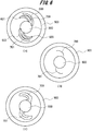
- Fig. 6(a) shows guides 600 to 603 formed of the flexible material on a lower mold 900 of the above resin mold, elastic materials 700 and 701 placed on the lower mold 900, and a flexible material 800 forming the optical portion.
- the elastic materials 700 and 701 are placed so as to be sandwiched between the guides 600 to 603 when viewed from over the lower mold, and the elastic materials 700 and 701 are positioned by the guides 600 to 603. Since the elastic materials 700 and 701 are the shaft portion 122 of the intraocular lens 10 and are placed at a position away from the flexible material 800 forming the optical portion 11, the configuration is fabricated such that the shaft portion 122 in the intraocular lens 10 after manufacture is provided away from the optical portion 11.
- Fig. 6(b) shows an example of a state in which the polymerization of the monomer is completed in the lower mold 900.
- the guides 600 to 603 formed in Fig. 6(a) disappear at this stage because the monomer is poured around them.
- alignment for cutting out the intraocular lens is performed, and then the outer shape of the intraocular lens is cut out.
- Fig. 6(c) shows an example of the intraocular lens to be cut out from the lower mold 900. As shown in Fig.
- the monomer in a region which is formed by polymerization and includes the elastic materials 700 and 701 and the flexible material 800 forming the optical portion is cut out. Further, the region surrounding the elastic materials 700 and 701 is cut out with a margin for forming the support portion 12 and the joint portion 13.
- the intraocular lens thus cut out is subjected to a process which is the same as the process of producing the conventional one-piece intraocular lens to complete the intraocular lens of the present embodiment.
- the support portion 12 of the intraocular lens 10 obtained by the above-described manufacturing method includes the shaft portion 122 formed of the elastic material and the main body 121 formed of the flexible material 800.
- the main body 121 is provided so as to cover the shaft portion 122, and the joint portion 13 between the support portion 12 and the optical portion 11 is configured such that the shaft portion 122 is provided away from the optical portion 11, so that when the support portion 12 is bent, the resulting repulsive force is a repulsive force with a magnitude between a magnitude of the repulsive force of the support portion of the conventional one-piece intraocular lens and a magnitude of the repulsive force of the support portion of the conventional multi-piece intraocular lens.
- the intraocular lens 10 of the present embodiment as an intraocular lens that is more suitable for the conditions of the patient's eye.
- a lower mold 1200 is provided with cross-link portions 1300 to 1303 supporting the elastic material which is the shaft portion 122 of the support portions 12.
- the cross-link portions 1300 to 1303 can be formed, for example, by a method of polymerizing a monomer of a flexible material in the same manner as the guides 600 to 603. Then, an elastic material 1000 is placed on the cross-link portions 1300 and 1301, and an elastic material 1001 is placed on the cross-link portions 1302 and 1303.
- the intraocular lens can be manufactured by pouring and polymerizing the monomer of the flexible material in the same manner as described above in a state where the elastic materials 1000 and 1001 are placed on the cross-link portions 1300 to 1303.
- Figs. 8(a) and 8(b) show an example of an intraocular lens 1500 manufactured in this modification.
- the same components as those in the above-described embodiment are denoted by the same reference numerals, and detailed descriptions thereof will be omitted.
- a support portion 1400 of the intraocular lens 1500 after manufacture has portions 1401 to 1404 of the shaft portion 122 wherein the portions are not covered by the main body 121.
- the repulsive force such as stress at the time of compression of the support portion 1400 is changed by changing the number and size of the portions of the shaft portion 122 wherein the portions are not covered by the main body 121.
- portions 1401 to 1404 of the shaft portion 122 wherein the portions are not covered by the main body 121 are provided in portions other than the portions which are bent most when the support portion 1400 is bent.
- the optical surface may be formed by processing the optical surface after polymerization.
Landscapes
- Health & Medical Sciences (AREA)
- Ophthalmology & Optometry (AREA)
- Life Sciences & Earth Sciences (AREA)
- Veterinary Medicine (AREA)
- Oral & Maxillofacial Surgery (AREA)
- Transplantation (AREA)
- Public Health (AREA)
- General Health & Medical Sciences (AREA)
- Animal Behavior & Ethology (AREA)
- Engineering & Computer Science (AREA)
- Vascular Medicine (AREA)
- Heart & Thoracic Surgery (AREA)
- Biomedical Technology (AREA)
- Cardiology (AREA)
- Chemical & Material Sciences (AREA)
- Dermatology (AREA)
- Medicinal Chemistry (AREA)
- Epidemiology (AREA)
- Prostheses (AREA)
- Materials For Medical Uses (AREA)
Applications Claiming Priority (2)
| Application Number | Priority Date | Filing Date | Title |
|---|---|---|---|
| JP2017008924A JP6937122B2 (ja) | 2017-01-20 | 2017-01-20 | 眼内レンズおよびその製造方法 |
| PCT/IB2018/000036 WO2018134674A1 (ja) | 2017-01-20 | 2018-01-29 | 眼内レンズおよびその製造方法 |
Publications (2)
| Publication Number | Publication Date |
|---|---|
| EP3572041A1 true EP3572041A1 (de) | 2019-11-27 |
| EP3572041A4 EP3572041A4 (de) | 2020-10-14 |
Family
ID=62908328
Family Applications (1)
| Application Number | Title | Priority Date | Filing Date |
|---|---|---|---|
| EP18741500.5A Withdrawn EP3572041A4 (de) | 2017-01-20 | 2018-01-29 | Intraokularlinse und verfahren zur herstellung davon |
Country Status (7)
| Country | Link |
|---|---|
| US (1) | US20190358026A1 (de) |
| EP (1) | EP3572041A4 (de) |
| JP (1) | JP6937122B2 (de) |
| KR (1) | KR20190104196A (de) |
| CN (1) | CN110325150A (de) |
| SG (1) | SG11201906674UA (de) |
| WO (1) | WO2018134674A1 (de) |
Families Citing this family (1)
| Publication number | Priority date | Publication date | Assignee | Title |
|---|---|---|---|---|
| US11951699B2 (en) | 2021-08-05 | 2024-04-09 | Amo Groningen B.V. | Method and assembly for forming an intraocular lens |
Family Cites Families (8)
| Publication number | Priority date | Publication date | Assignee | Title |
|---|---|---|---|---|
| US4576607A (en) | 1984-07-13 | 1986-03-18 | Kelman Charles D | Intraocular lenses |
| JPH01300948A (ja) * | 1988-05-31 | 1989-12-05 | Canon Inc | 眼内レンズ |
| US5928282A (en) * | 1997-06-13 | 1999-07-27 | Bausch & Lomb Surgical, Inc. | Intraocular lens |
| US6942695B1 (en) * | 1999-04-05 | 2005-09-13 | Wessley-Jessen Corporation | Biomedical devices with polyimide coating |
| US6200344B1 (en) * | 1999-04-29 | 2001-03-13 | Bausch & Lomb Surgical, Inc. | Inraocular lenses |
| US6190410B1 (en) * | 1999-04-29 | 2001-02-20 | Bausch & Lomb Surgical, Inc. | Intraocular lenses |
| US20060064162A1 (en) * | 2004-09-17 | 2006-03-23 | Klima William L | 333Intraocular lens device |
| JP2008086508A (ja) | 2006-09-29 | 2008-04-17 | Hoya Corp | 眼内観察用レンズ装置及び眼内観察用レンズ保持装置 |
-
2017
- 2017-01-20 JP JP2017008924A patent/JP6937122B2/ja not_active Expired - Fee Related
-
2018
- 2018-01-29 US US16/479,570 patent/US20190358026A1/en not_active Abandoned
- 2018-01-29 EP EP18741500.5A patent/EP3572041A4/de not_active Withdrawn
- 2018-01-29 KR KR1020197023190A patent/KR20190104196A/ko not_active Abandoned
- 2018-01-29 SG SG11201906674UA patent/SG11201906674UA/en unknown
- 2018-01-29 CN CN201880007696.7A patent/CN110325150A/zh active Pending
- 2018-01-29 WO PCT/IB2018/000036 patent/WO2018134674A1/ja not_active Ceased
Also Published As
| Publication number | Publication date |
|---|---|
| WO2018134674A8 (ja) | 2018-11-01 |
| KR20190104196A (ko) | 2019-09-06 |
| EP3572041A4 (de) | 2020-10-14 |
| CN110325150A (zh) | 2019-10-11 |
| JP2018183197A (ja) | 2018-11-22 |
| SG11201906674UA (en) | 2019-08-27 |
| WO2018134674A1 (ja) | 2018-07-26 |
| JP6937122B2 (ja) | 2021-09-22 |
| US20190358026A1 (en) | 2019-11-28 |
Similar Documents
| Publication | Publication Date | Title |
|---|---|---|
| EP2584954B1 (de) | Adaptive patientenschnittstelle | |
| AU2012335677B2 (en) | Accommodating intraocular lenses and methods of use | |
| JP5816289B2 (ja) | 眼内レンズシステム | |
| RU2232561C2 (ru) | Внутриглазной хрусталик, имеющий конструкцию для регулирования его осевого смещения после имплантации | |
| EP2221024A1 (de) | Intraokularlinse, die zum Kompensieren von optischen Effekten, die von optischer Verformung verursacht werden, eingerichtet ist | |
| KR20000070616A (ko) | 안내 렌즈 및 일체형 안내 렌즈의 제조 방법 | |
| CN111358594B (zh) | 有晶体眼人工晶状体 | |
| US20200054444A1 (en) | Intraocular lens system with folding features | |
| US8449611B2 (en) | Intraocular lens | |
| JP7001823B2 (ja) | 眼内レンズ | |
| AU2013211203B2 (en) | Implant device, sensor module, disposable injector with an implant device and method for producing an implant device | |
| JP2024091872A (ja) | 眼科手術練習装置 | |
| EP3572041A1 (de) | Intraokularlinse und verfahren zur herstellung davon | |
| EP2695585B1 (de) | Kontaktlinsenentwurfsverfahren und kontaktlinse | |
| JPH0767896A (ja) | 眼内レンズ | |
| HK40015444A (en) | Intraocular lens and method for producing same | |
| CN214073755U (zh) | 有晶体眼人工晶状体 | |
| CN115245404A (zh) | 用于生产可调节人工晶状体的方法 | |
| JP4499804B2 (ja) | 目の角膜の局所的変形を補償する手段と装置 | |
| US12616565B2 (en) | Pinhole intraocular onlay | |
| US20230240834A1 (en) | Pinhole Intraocular Onlay | |
| KR102814498B1 (ko) | 인공 수정체낭 | |
| RU75151U1 (ru) | Искусственный хрусталик глаза | |
| AU2015202338A1 (en) | Adaptive patient interface | |
| CN112716657A (zh) | 一种人工晶状体定位器 |
Legal Events
| Date | Code | Title | Description |
|---|---|---|---|
| STAA | Information on the status of an ep patent application or granted ep patent |
Free format text: STATUS: THE INTERNATIONAL PUBLICATION HAS BEEN MADE |
|
| PUAI | Public reference made under article 153(3) epc to a published international application that has entered the european phase |
Free format text: ORIGINAL CODE: 0009012 |
|
| STAA | Information on the status of an ep patent application or granted ep patent |
Free format text: STATUS: REQUEST FOR EXAMINATION WAS MADE |
|
| 17P | Request for examination filed |
Effective date: 20190801 |
|
| AK | Designated contracting states |
Kind code of ref document: A1 Designated state(s): AL AT BE BG CH CY CZ DE DK EE ES FI FR GB GR HR HU IE IS IT LI LT LU LV MC MK MT NL NO PL PT RO RS SE SI SK SM TR |
|
| AX | Request for extension of the european patent |
Extension state: BA ME |
|
| XX | Miscellaneous |
Free format text: THE RESTORATION OF THE RIGHT OF PRIORITY GRANTED BY THE RECEIVING OFFICE IS EFFECTIVE BEFORE THE EPO (R. 49TER.1(A) PCT). |
|
| DAV | Request for validation of the european patent (deleted) | ||
| DAX | Request for extension of the european patent (deleted) | ||
| A4 | Supplementary search report drawn up and despatched |
Effective date: 20200914 |
|
| RIC1 | Information provided on ipc code assigned before grant |
Ipc: A61L 27/14 20060101ALI20200908BHEP Ipc: A61F 2/16 20060101AFI20200908BHEP |
|
| STAA | Information on the status of an ep patent application or granted ep patent |
Free format text: STATUS: THE APPLICATION HAS BEEN WITHDRAWN |
|
| 18W | Application withdrawn |
Effective date: 20210916 |