EP3569036B1 - Commande d'éclairage - Google Patents
Commande d'éclairage Download PDFInfo
- Publication number
- EP3569036B1 EP3569036B1 EP18700151.6A EP18700151A EP3569036B1 EP 3569036 B1 EP3569036 B1 EP 3569036B1 EP 18700151 A EP18700151 A EP 18700151A EP 3569036 B1 EP3569036 B1 EP 3569036B1
- Authority
- EP
- European Patent Office
- Prior art keywords
- light
- light source
- pupil
- property
- human user
- Prior art date
- Legal status (The legal status is an assumption and is not a legal conclusion. Google has not performed a legal analysis and makes no representation as to the accuracy of the status listed.)
- Active
Links
- 210000001747 pupil Anatomy 0.000 claims description 72
- 230000004071 biological effect Effects 0.000 claims description 20
- 238000000034 method Methods 0.000 claims description 11
- 238000001429 visible spectrum Methods 0.000 claims description 6
- 230000004044 response Effects 0.000 claims description 4
- 230000003595 spectral effect Effects 0.000 claims description 4
- 238000004590 computer program Methods 0.000 claims description 2
- 230000007704 transition Effects 0.000 claims description 2
- 238000001228 spectrum Methods 0.000 description 20
- 230000000694 effects Effects 0.000 description 15
- 230000001225 therapeutic effect Effects 0.000 description 8
- 230000008859 change Effects 0.000 description 7
- 230000036626 alertness Effects 0.000 description 6
- 239000011521 glass Substances 0.000 description 6
- 230000001447 compensatory effect Effects 0.000 description 5
- 230000007613 environmental effect Effects 0.000 description 5
- 210000001525 retina Anatomy 0.000 description 5
- 230000006399 behavior Effects 0.000 description 4
- 230000008901 benefit Effects 0.000 description 3
- 230000007423 decrease Effects 0.000 description 3
- 230000036541 health Effects 0.000 description 3
- 230000001766 physiological effect Effects 0.000 description 3
- 230000027288 circadian rhythm Effects 0.000 description 2
- 239000003086 colorant Substances 0.000 description 2
- 230000003247 decreasing effect Effects 0.000 description 2
- 238000010586 diagram Methods 0.000 description 2
- 230000006870 function Effects 0.000 description 2
- 230000004048 modification Effects 0.000 description 2
- 238000012986 modification Methods 0.000 description 2
- 230000003287 optical effect Effects 0.000 description 2
- 230000009467 reduction Effects 0.000 description 2
- 208000012672 seasonal affective disease Diseases 0.000 description 2
- 238000011282 treatment Methods 0.000 description 2
- 230000036642 wellbeing Effects 0.000 description 2
- 230000004913 activation Effects 0.000 description 1
- 230000003044 adaptive effect Effects 0.000 description 1
- 230000033228 biological regulation Effects 0.000 description 1
- 230000002060 circadian Effects 0.000 description 1
- 238000004883 computer application Methods 0.000 description 1
- 208000037265 diseases, disorders, signs and symptoms Diseases 0.000 description 1
- 230000004907 flux Effects 0.000 description 1
- 238000005286 illumination Methods 0.000 description 1
- 230000006872 improvement Effects 0.000 description 1
- 230000003993 interaction Effects 0.000 description 1
- 238000005259 measurement Methods 0.000 description 1
- 239000000203 mixture Substances 0.000 description 1
- 238000001126 phototherapy Methods 0.000 description 1
- 230000004800 psychological effect Effects 0.000 description 1
- 230000002040 relaxant effect Effects 0.000 description 1
- 230000002123 temporal effect Effects 0.000 description 1
Images


Classifications
-
- H—ELECTRICITY
- H05—ELECTRIC TECHNIQUES NOT OTHERWISE PROVIDED FOR
- H05B—ELECTRIC HEATING; ELECTRIC LIGHT SOURCES NOT OTHERWISE PROVIDED FOR; CIRCUIT ARRANGEMENTS FOR ELECTRIC LIGHT SOURCES, IN GENERAL
- H05B47/00—Circuit arrangements for operating light sources in general, i.e. where the type of light source is not relevant
- H05B47/10—Controlling the light source
- H05B47/105—Controlling the light source in response to determined parameters
- H05B47/11—Controlling the light source in response to determined parameters by determining the brightness or colour temperature of ambient light
-
- A—HUMAN NECESSITIES
- A61—MEDICAL OR VETERINARY SCIENCE; HYGIENE
- A61M—DEVICES FOR INTRODUCING MEDIA INTO, OR ONTO, THE BODY; DEVICES FOR TRANSDUCING BODY MEDIA OR FOR TAKING MEDIA FROM THE BODY; DEVICES FOR PRODUCING OR ENDING SLEEP OR STUPOR
- A61M21/00—Other devices or methods to cause a change in the state of consciousness; Devices for producing or ending sleep by mechanical, optical, or acoustical means, e.g. for hypnosis
- A61M21/02—Other devices or methods to cause a change in the state of consciousness; Devices for producing or ending sleep by mechanical, optical, or acoustical means, e.g. for hypnosis for inducing sleep or relaxation, e.g. by direct nerve stimulation, hypnosis, analgesia
-
- H—ELECTRICITY
- H05—ELECTRIC TECHNIQUES NOT OTHERWISE PROVIDED FOR
- H05B—ELECTRIC HEATING; ELECTRIC LIGHT SOURCES NOT OTHERWISE PROVIDED FOR; CIRCUIT ARRANGEMENTS FOR ELECTRIC LIGHT SOURCES, IN GENERAL
- H05B45/00—Circuit arrangements for operating light-emitting diodes [LED]
- H05B45/10—Controlling the intensity of the light
- H05B45/12—Controlling the intensity of the light using optical feedback
-
- H—ELECTRICITY
- H05—ELECTRIC TECHNIQUES NOT OTHERWISE PROVIDED FOR
- H05B—ELECTRIC HEATING; ELECTRIC LIGHT SOURCES NOT OTHERWISE PROVIDED FOR; CIRCUIT ARRANGEMENTS FOR ELECTRIC LIGHT SOURCES, IN GENERAL
- H05B45/00—Circuit arrangements for operating light-emitting diodes [LED]
- H05B45/20—Controlling the colour of the light
- H05B45/22—Controlling the colour of the light using optical feedback
-
- H—ELECTRICITY
- H05—ELECTRIC TECHNIQUES NOT OTHERWISE PROVIDED FOR
- H05B—ELECTRIC HEATING; ELECTRIC LIGHT SOURCES NOT OTHERWISE PROVIDED FOR; CIRCUIT ARRANGEMENTS FOR ELECTRIC LIGHT SOURCES, IN GENERAL
- H05B47/00—Circuit arrangements for operating light sources in general, i.e. where the type of light source is not relevant
- H05B47/10—Controlling the light source
- H05B47/105—Controlling the light source in response to determined parameters
- H05B47/115—Controlling the light source in response to determined parameters by determining the presence or movement of objects or living beings
- H05B47/125—Controlling the light source in response to determined parameters by determining the presence or movement of objects or living beings by using cameras
-
- H—ELECTRICITY
- H05—ELECTRIC TECHNIQUES NOT OTHERWISE PROVIDED FOR
- H05B—ELECTRIC HEATING; ELECTRIC LIGHT SOURCES NOT OTHERWISE PROVIDED FOR; CIRCUIT ARRANGEMENTS FOR ELECTRIC LIGHT SOURCES, IN GENERAL
- H05B47/00—Circuit arrangements for operating light sources in general, i.e. where the type of light source is not relevant
- H05B47/10—Controlling the light source
- H05B47/16—Controlling the light source by timing means
-
- H—ELECTRICITY
- H05—ELECTRIC TECHNIQUES NOT OTHERWISE PROVIDED FOR
- H05B—ELECTRIC HEATING; ELECTRIC LIGHT SOURCES NOT OTHERWISE PROVIDED FOR; CIRCUIT ARRANGEMENTS FOR ELECTRIC LIGHT SOURCES, IN GENERAL
- H05B47/00—Circuit arrangements for operating light sources in general, i.e. where the type of light source is not relevant
- H05B47/10—Controlling the light source
- H05B47/175—Controlling the light source by remote control
- H05B47/19—Controlling the light source by remote control via wireless transmission
-
- H—ELECTRICITY
- H05—ELECTRIC TECHNIQUES NOT OTHERWISE PROVIDED FOR
- H05B—ELECTRIC HEATING; ELECTRIC LIGHT SOURCES NOT OTHERWISE PROVIDED FOR; CIRCUIT ARRANGEMENTS FOR ELECTRIC LIGHT SOURCES, IN GENERAL
- H05B47/00—Circuit arrangements for operating light sources in general, i.e. where the type of light source is not relevant
- H05B47/10—Controlling the light source
- H05B47/175—Controlling the light source by remote control
- H05B47/196—Controlling the light source by remote control characterised by user interface arrangements
- H05B47/1965—Controlling the light source by remote control characterised by user interface arrangements using handheld communication devices
-
- A—HUMAN NECESSITIES
- A61—MEDICAL OR VETERINARY SCIENCE; HYGIENE
- A61M—DEVICES FOR INTRODUCING MEDIA INTO, OR ONTO, THE BODY; DEVICES FOR TRANSDUCING BODY MEDIA OR FOR TAKING MEDIA FROM THE BODY; DEVICES FOR PRODUCING OR ENDING SLEEP OR STUPOR
- A61M21/00—Other devices or methods to cause a change in the state of consciousness; Devices for producing or ending sleep by mechanical, optical, or acoustical means, e.g. for hypnosis
- A61M2021/0005—Other devices or methods to cause a change in the state of consciousness; Devices for producing or ending sleep by mechanical, optical, or acoustical means, e.g. for hypnosis by the use of a particular sense, or stimulus
- A61M2021/0044—Other devices or methods to cause a change in the state of consciousness; Devices for producing or ending sleep by mechanical, optical, or acoustical means, e.g. for hypnosis by the use of a particular sense, or stimulus by the sight sense
-
- A—HUMAN NECESSITIES
- A61—MEDICAL OR VETERINARY SCIENCE; HYGIENE
- A61M—DEVICES FOR INTRODUCING MEDIA INTO, OR ONTO, THE BODY; DEVICES FOR TRANSDUCING BODY MEDIA OR FOR TAKING MEDIA FROM THE BODY; DEVICES FOR PRODUCING OR ENDING SLEEP OR STUPOR
- A61M2210/00—Anatomical parts of the body
- A61M2210/06—Head
- A61M2210/0612—Eyes
Definitions
- the present disclosure relates to systems and methods for managing biological effects of a lighting device on a user.
- Different parts of the light spectrum are known to have effects on human behaviour and well-being. This is particularly true for light entering the human eye, where the light can cause both physiological effects (e.g. circadian rhythm regulation) and psychological effects (e.g. a relaxing atmosphere).
- physiological effects e.g. circadian rhythm regulation
- psychological effects e.g. a relaxing atmosphere.
- the blue part of the spectrum (around 480nm) is known to affect circadian rhythm, alertness and quality of sleep, and is used in light therapy for the treatment of conditions such as Seasonal Affective Disorder (SAD).
- SAD Seasonal Affective Disorder
- colour temperature is a known term.
- the colour temperature of a light source is equal to the temperature of an ideal black-body radiator which produces a comparable hue to the light source, usually expressed in Kelvin.
- a higher colour temperature light source outputs more light in the blue part of the spectrum.
- US 2016/341436 A1 discloses a method comprising: (a) receiving a set of physiological data associated with at least one health condition of a human subject; (b) receiving a set of environmental data associated with one or more environment conditions to which the human subject is or has been exposed; (c) determining a set of operating parameters for at least one environmental device based at least partially on at least a portion of the set of physiological data and at least a portion of the set of environmental data; and (d) transmitting the set of operating parameters to the at least one environmental device to at least partially control at least one controlled environmental condition to which the human subject is exposed to thereby at partially control the at least one health condition.
- the health condition controlled is a circadian biorhythm of the human subject.
- the present invention adds light external to the light emitting device to reduce the negative impact of blue light in an adaptive way.
- the idea is based on the knowledge that the pupil size is directly influenced by the amount of light incident on the eyes i.e. more light results in a smaller pupil size.
- the pupil regulates the amount of light in the eye and most importantly at the photo-sensitive part of the eye: the retina.
- a smaller pupil size reduces the light incidence.
- the resulting reduction in pupil size reduces the total amount of blue light at the retina (even though there is overall more light).
- a human pupil has a minimum size which is typically around 2mm in diameter.
- spectral power distribution or intensity of the light emitted from the device. This is especially advantageous for use of display devices (such as mobile devices, tablets, computer screens or television screens) that are not controllable in terms of light settings such as brightness or color temperature or of which the user prefers not to change these light settings for reasons of comfortable reading/viewing.
- display devices such as mobile devices, tablets, computer screens or television screens
- light settings such as brightness or color temperature or of which the user prefers not to change these light settings for reasons of comfortable reading/viewing.
- a controller for controlling a first light source to emit light into a pupil of a human user in order to reduce at least one biological effect of light from a second light source on the human user according to claim 1.
- the first light source can be controlled to compensate for light emitted by the uncontrollable second light source.
- said controlling the light output of the first light source comprises increasing the brightness of the light output of the first light source, in particular, the luminous intensity of the light (i.e. the intensity within the visible spectrum).
- said data indicating a property of the light from the second light source is received from a light sensor detecting the property of the light from the second light source.
- said data indicating a property of the light from the second light source is received from a database storing properties of the second light source.
- Said property is a substantial luminance in a blue part of the visible spectrum.
- “Substantial” in this context means a sufficiently high relative intensity of the blue part of the visible spectrum to induce physiological effects associated with blue light. That is, the intensity of a blue part of the spectrum (for example above about 450nm) is sufficiently high relative to the rest of the visible spectrum to induce such physiological effects.
- the processor is arranged to perform said control of the first light source based on a time constant specifying a transition time from a first light output setting of the first light source to a second light output setting of the first light source.
- the second light source is a screen of a computing device.
- the second light source is a luminaire arranged to illuminate an environment of the human user.
- the controller and first light source form a sub-system ("compensatory system") which may be selectively turned on and off by the human user.
- a user device According to a second aspect disclosed herein, there is provided a user device according to claim 5.
- the first light source is a light source separate from the user device.
- the first light source may be integrated into a device other than the user device comprising the camera (such as a different second user device e.g. a wearable headset), or may be another light source separate from the user device such as a luminaire arranged to illuminate an environment of the user.
- a method of controlling a first light source to emit light into a pupil of a human user in order to reduce at least one biological effect of light from a second light source on the human user according to claim 9.
- a computer program product comprising computer-executable code embodied on a computer-readable storage medium arranged so as when executed by one or more processing units to perform the method according to any the fourth aspect.
- Figure 1 shows a system according to a preferred embodiment of the present invention.
- the system comprises a first light source 101, a second light source 102, a light sensor 301, a pupil sensor 302, and a controller 400. Also shown is a human eye 200.
- the second light source 102 may be any device which produces a light output and hence may be a dedicated lighting device such as a luminaire (e.g. an incandescent bulb, fluorescent bulb, LED luminaire etc.) or may be a device which produces a light output but has a primary purpose other than illumination (e.g. a computer screen or screen of a mobile device as shown in Figure 1 ).
- a luminaire e.g. an incandescent bulb, fluorescent bulb, LED luminaire etc.
- a primary purpose other than illumination e.g. a computer screen or screen of a mobile device as shown in Figure 1 .
- the second light source 102 is arranged such that light output from the second light source 102 enters the eye 200 via the pupil of the eye 200. Together, the second light source 102 and the eye 200 represent a "sub-system" 110 which is commonplace. As mentioned above, light from the second light source 102 entering the eye 200 of a human being or a user may create a biological effect (either physiological or psychological) on the user.
- the biological effect of the second light source 102 may be either wanted or unwanted by the user.
- the present invention allows for the decreasing of unwanted effects from the second light source 102 even when the second light source 102 is not directly controllable by the user.
- the terms wanted and unwanted may be also interpreted as desired or undesired. That is, the second light source 102 may be part of an entirely separate lighting system over which the user has no control. In these cases, the user may wish to decrease an unwanted effect of the lighting but may have no means by which to alter the settings of the second light source 102.
- the present invention nevertheless allows the user to decrease the unwanted effect of the second lighting source 102 by way of the further elements in Figure 1 described below.
- a controller 400 is provided which receives input from a light sensor 301 and a pupil sensor 302, and generates control commands for controlling the first light source 101.
- the first light source 101 may comprise one or more individual lighting devices such as LEDs, incandescent or fluorescent bulbs etc.
- the first light source 101 can be a lamp, but can also be a light source of any other device (e.g. a connected device such as a smart phone) with multiple relatively narrowband LED's or colour filters, for example a TV which emits a combination of green and red light.
- the light sensor 301 measures the power spectrum of the light hitting the eye 200 from the second light source 102. E.g. the light sensor 301 measures the amount of blue light in the spectrum of the light output by the second light source 102.
- the light sensor 301 is arranged such that it also detects light from the first light source 101, the contribution from the first light source 101 can be removed from the sensor readings using knowledge of the output properties of the first light source 101 (which are readily available to the system as the first light source 101 is controlled by the system).
- the pupil sensor 302 measures the size of the pupil of the user's eye 200.
- the pupil sensor 302 may comprise a camera for taking an image of the user's eye 200, from which a size of the pupil can be determined using known image processing techniques.
- the camera may be a visible light camera but may also be a (near-) infrared camera, and an estimate of the pupil size can be determined based on reflected light from the eye 200. That is, light can be directed to the eye 200 and the amount of light returned/reflected by the eye 200 can be measured as an indication of pupil size, based on the fact that the pupil is black and most light falling onto the pupil will pass through it. The larger the pupil, the less light is reflected. Again, techniques for doing so are well-known in the art.
- the controller 400 drives the first light source 101 depending on the data coming from the sensors 301, 302.
- the controller 400 determines the spectral output of the first light source 101 that is required to reduce the unwanted effects from the light originating from the second light source 102.
- the controller 400 increases the light intensity or brightness of the blue deprived light from the first light source 101 when there is excessive or too much blue light from the second light source 102 hitting the eye (as measured by the light sensor 301) but only if pupil diameter is larger than a minimum size.
- the blue deprive light from the first light source 101 can be provided so that there is minimal or no change to the ambient lighting settings, e.g. by means of a dedicated light source close to or in proximity of the user such as a spot light or reading light or close to or in proximity of the eye(s) of the user such as integrated in glasses or another wearable device.
- controller 400 information regarding whether or not the effect is wanted can be provided to the controller 400 by the user, e.g. via a user device described later, and stored in memory by the controller 400 as described in more detail below.
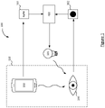
- Figure 2 shows an alternative system which does not comprise the light sensor 301. Instead, information pertaining to the second light source 102 (e.g. information indicating the type of device the second light source 102 is built into) is received by the controller 400 and then used by the controller 400 to retrieve information about the light output of the second light source 102 from a memory such as database 500 shown in Figure 2 .
- the database 500 may be an external database accessible over a network or may be an internal memory of the controller 400 itself. That is, rather than measuring the light falling onto the eye 200, the controller 400 uses the database 500 to find out what the spectrum of the second light source 201 is.
- the second light source 201 is part of a computing device, e.g.
- the second light source 201 is a screen of a tablet or mobile device
- the user 600 is looking into the light source 201 if the device is turned on or active or at least that some light from the second light source 201 is entering the eye 200 of the user.
- Whether the device is active or not can be gauged by checking WiFi activity or the presence of a Bluetooth signal of the device, as is known in the art.
- Figure 3 shows a schematic diagram of the controller 400.
- the controller comprises a first input 401, a second input 402, a processor 403, and an output 404.
- the controller 400 may also comprise an internal memory (not shown).
- Figure 3 also shows the user 600 and a user device 601 of the user 600 (e.g. a mobile device or other computing device) which may be used, as described above, by the user 600 to provide an indication of whether or not a particular biological effect is wanted or unwanted.
- a user device 601 of the user 600 e.g. a mobile device or other computing device
- the first input 401 is configured to receive light property data indicating a property of the light from the second light source, said property being of a type which causes a biological effect on the human user.
- this may comprise receiving light property data which were sensed directly by light sensor 301 (this is shown in Figure 3 ) or, as shown in Figure 2 , this may comprise retrieving light property data from database 500 (this is not shown in Figure 3 ).
- the controller 400 is able to determine therefrom whether or not the light will have a biological effect on the user.
- the controller 400 is also able to determine whether or not this effect is wanted or unwanted by the user, based on e.g. a stored indication as mentioned above.
- the second input 402 is configured to receive pupil sensor data from the pupil sensor 302 detecting a size of the pupil of the human user.
- the output 404 is configured for sending control commands to the first light source 101. Methods for doing so are well-known in the art and so not described in detail here.
- the processor 403 is configured to determine, using the light property data received via the first input, that the light from the second light source has said property; in response to said determination that the light from the second light source has said property, determine, using said pupil sensor data received via the second input, a current size of the pupil; and on condition that the current size of the pupil is determined to be outside of a desired range, control light output of the first light source in order to bring the pupil size inside said desired range.
- Whether or not the pupil is outside of a desired range need not be determined from direct pupil size measurement but can also be inferred from other factors. For example, the determination that the pupil size is larger than a minimum size can be inferred from on the amount of ambient light present. If this light level is below a threshold, it can be assumed that the pupil is not its minimum size.
- the second light source 102 may be a screen of a computing device on which the user 600 is watching a video (e.g. a tablet, phone, or computer).
- the device may emit excessive blue light (as is common with illuminated screens) which may be unwanted, e.g. at night when the user 600 wishes to sleep shortly thereafter.
- the light sensor 301 may be positioned close to the user's eye 200 (e.g. integrated in a wearable device such as glasses) and detects that the spectrum of the light from the second light source 102 comprises a high amount of blue.
- the pupil sensor 302 may be a camera and may also be implemented in the glasses but may also be implemented in the computing device itself, such as a front-facing camera of the computing device capturing an image of the user.
- the controller 400 may be implemented in the computing device itself, in the glasses mentioned above, be part of the first light source 101 or be a separate controller functionally connected with input devices such as the sensors 301 and 302 described above and output devices such as the first light source 101 described above.
- the sensors 301, 302 and the controller 400 preferably communicate wirelessly (e.g. WiFi) but it is not excluded that they are connected via hard wired connections, or a combination of wired and wireless connections.
- the amount of light of the computing device light source i.e. the second light source 102
- the amount of ambient light i.e.
- the first light source 101 will be increased to reduce the pupil diameter and therewith reduce the amount of blue light received at the retina. If the pupil size is minimal (around 2 mm), adding light will not change pupil diameter anymore and consequently the amount of blue light hitting the retina cannot be further reduced.
- the controller 400, light sensor 301, and pupil sensor 302 are all implemented in the same physical device such as a tablet or smart phone (i.e. user device 601) operated by the user 600.
- the light sensor 301 and the pupil sensor 302 may be implemented in the user device 601 and the controller 400 implemented in an external computing device such as a server to which the sensor data are transmitted for processing.
- the first light source 101 is an ambient light source such as room lighting within an environment and is already controlled by a controller.
- Figures 4A and 4B illustrate one advantage of the present invention.
- Figure 4A shows the incidence of light from a second light source 102 alone on the eye 200 and
- Figure 4B shows the improvement offered by adding light from the first light source 101 as in the present invention.
- an example spectrum 152 of the light output by the second light source 102 is shown entering the eye 200.
- the spectrum 152 comprises a significant amount of power within a therapeutic window 700.
- the therapeutic window 700 is shown in this example as comprising blue wavelengths of light, but it is understood that different ranges of the spectrum may be of interest for different biological effects.
- the therapeutic window shown in Figure 4A may, for example, be particularly effective for increasing alertness in the user 600.
- the processor 403 receives information about the spectrum 152 wherein the information at least includes whether or not the light produces a biological effect, as described above.
- the biological effect is alertness
- the processor 403 determines that the light from the second light source 102 does indeed produce this effect on the user 600.
- the processor 403 further determines whether or not this effect is desired by the user 600, e.g. based on user input from user device 601 as mentioned above. This determination may also be assumed by the processor 403 based on other information. For example, the "alertness" effect may be assumed to be wanted during morning hours (e.g. 7am-9am) and unwanted at night (e.g. 9pm onwards).
- the processor 403 also receives information about the pupil size of the user's eye 200.
- the pupil 201 is large and the processor 403 determines whether or not the pupil 201 is larger than the minimum size.
- the pupil size is larger than a minimum size, such as 2 mm for human pupils, and the alertness effect of the blue light entering the pupil 201 is unwanted by the user 600, such as explicitly specified by the user via user device 601 or as assumed because of night time.
- Figure 4B shows the same situation as Figure 4A , but with the addition of the first light source 101 in accordance with the present invention.
- the first light source 101 has an output spectrum shown by spectrum 151.
- the first light source 101 does not output significant power within the therapeutic window 700. That is, the first light source 101 does not produce the alertness effect as the second light source 102 does.
- the processor 403 has determined that the second light source 102 is outputting light having a biological effect on the user 600 which is unwanted.
- the processor 403 has also determined that the pupil 201 is larger than the minimum size.
- the processor 403 controls the first light source 101 to increase its light output, especially in the light spectrum outside the therapeutic window 700. This increases the total amount of light (i.e. combined from the first light source 101 and the second light source 102) incident on the eye 200 and therefore causes the pupil 201 to shrink.
- light output refers to the intensity of the first light source 101, which may correlate with the perceived brightness by a human user perceiving the light.
- the size of the pupil 201 has now been reduced by increasing the total amount of light provided to the user's eye 200 but without increasing the total amount of blue light (i.e. the overall optical power within the therapeutic window 700) because the additional light comprised reddish light (i.e. optical power outside the therapeutic window 700).
- blue light i.e. the overall optical power within the therapeutic window 700
- reddish light i.e. optical power outside the therapeutic window 700
- modification of the first light source 101 directly based on the (total) amount of therapeutic light reaching the eye 200 may lead to unwanted oscillating behaviour in the output of this light source.
- the external light sources for example the first light source 101
- the controller 400 can set a time constant for light modifications.
- the controller 400 can "smooth out” temporal changes to the lighting settings of the first light source 101. If a high time constant is set, the first light source 101 reacts only slowly to changes in blue content measured by the sensor, while it reacts quickly when the time constant is low.
- the pupil size adjustments of a human eye are more sensitive to some wavelengths of light than others. Hence, controlling the colour temperature of the first light 101 can also be used to change the pupil size.
- the activation of the first light source 101 may be considered a "compensatory" system and may be optionally turned on and/or off by the user 600.
- the user device 601 may be used by the user 600 to specify when or where the compensatory light system should be active.
- the compensatory system is “off', the system functions as in sub-system 110 without interaction with the first light source 101 and controller 400.
- the compensatory system is "on", the system functions as described herein with the first light source 101 and controller 400 thereof being active. Any reference signs in the claims should not be construed as limiting the scope.
Landscapes
- Health & Medical Sciences (AREA)
- Engineering & Computer Science (AREA)
- Anesthesiology (AREA)
- Computer Networks & Wireless Communication (AREA)
- Biomedical Technology (AREA)
- Life Sciences & Earth Sciences (AREA)
- Acoustics & Sound (AREA)
- Psychology (AREA)
- Pain & Pain Management (AREA)
- Heart & Thoracic Surgery (AREA)
- Hematology (AREA)
- Physics & Mathematics (AREA)
- Animal Behavior & Ethology (AREA)
- General Health & Medical Sciences (AREA)
- Public Health (AREA)
- Veterinary Medicine (AREA)
- Circuit Arrangement For Electric Light Sources In General (AREA)
- Eye Examination Apparatus (AREA)
Claims (10)
- Organe de commande (400) pour commander une première source de lumière (101) pour émettre de la lumière dans une pupille (201) d'un utilisateur humain afin de réduire au moins un effet biologique d'une lumière provenant d'une seconde source de lumière (102) sur l'utilisateur humain, l'organe de commande comprenant :une première entrée (401) pour recevoir des données de propriété de lumière indiquant une propriété de la lumière provenant de la seconde source de lumière, ladite propriété étant une luminance dans une partie bleue du spectre visible suffisamment élevée pour induire un effet biologique sur l'utilisateur humain ;une seconde entrée (402) pour recevoir des données de pupille indiquant une taille de la pupille de l'utilisateur humain ;une sortie (404) pour envoyer des instructions de commande à la première source de lumière ;un processeur (403) configuré pour :déterminer, en utilisant les données de propriété de lumière reçues par l'intermédiaire de la première entrée, que la lumière provenant de la seconde source de lumière a ladite propriété ;caractérisé en ce queen réponse à ladite détermination que la lumière provenant de la seconde source de lumière a ladite propriété, déterminer, en utilisant lesdites données de pupille reçues par l'intermédiaire de la seconde entrée, une taille actuelle de la pupille ; età condition que la taille actuelle de la pupille soit déterminée comme étant plus grande qu'une taille minimale, commander la première source de lumière pour émettre de la lumière n'ayant pas ladite propriété dans la pupille et réduire de ce fait la taille de la pupille, sans changer une distribution de puissance spectrale ou une intensité de la lumière provenant de la seconde source de lumière.
- Organe de commande selon la revendication 1, dans lequel lesdites données indiquant une propriété de la lumière provenant de la seconde source de lumière sont reçues d'un capteur de lumière (301) détectant la propriété de la lumière provenant de la seconde source de lumière.
- Organe de commande selon la revendication 1, dans lequel lesdites données indiquant une propriété de la lumière provenant de la seconde source de lumière sont reçues d'une base de données stockant des propriétés de la seconde source de lumière.
- Organe de commande selon une quelconque revendication précédente, dans lequel le processeur est agencé pour mettre en oeuvre ladite commande de la première source de lumière avec une constante de temps spécifiant un temps de transition depuis un premier réglage de sortie de lumière de la première source de lumière vers un second réglage de sortie de lumière de la première source de lumière.
- Dispositif utilisateur comprenant l'organe de commande selon l'une quelconque des revendications précédentes et comprenant en outre une caméra, dans lequel la caméra est agencée pour capturer une image de la pupille de l'utilisateur humain et détecter la taille de la pupille de l'utilisateur humain et dans lequel la caméra est intégrée dans le dispositif utilisateur.
- Dispositif portable pour un utilisateur humain comprenant l'organe de commande selon la revendication 1 et comprenant en outre un capteur de lumière (301) agencé pour détecter la propriété de la lumière provenant de la seconde source de lumière et une caméra (302) agencée pour capturer une image de la pupille de l'utilisateur humain et détecter la taille de la pupille de l'utilisateur humain.
- Dispositif portable selon la revendication 6 comprenant en outre la première source de lumière (101).
- Système comprenant le dispositif utilisateur selon la revendication 5 ou le dispositif portable selon la revendication 6 et la première source de lumière.
- Procédé de commande d'une première source de lumière (101) pour émettre de la lumière dans une pupille (201) d'un utilisateur humain afin de réduire au moins un effet biologique d'une lumière provenant d'une seconde source de lumière (102) sur l'utilisateur humain, le procédé comprenant :la réception de données de propriété de lumière indiquant une propriété de la lumière provenant de la seconde source de lumière, ladite propriété étant une luminance dans une partie bleue du spectre visible suffisamment élevée pour induire un effet biologique sur l'utilisateur humain ;la réception de données de pupille indiquant une taille de la pupille de l'utilisateur humain ;la détermination, en utilisant les données de propriété de lumière, que la lumière provenant de la seconde source de lumière a ladite propriété ;caractérisé en ce queen réponse à ladite détermination que la lumière provenant de la seconde source de lumière a ladite propriété, on détermine, en utilisant lesdites données de pupille, une taille actuelle de la pupille ; età condition que la taille actuelle de la pupille soit déterminée comme étant plus grande qu'une taille minimale, la commande de la première source de lumière pour émettre de la lumière n'ayant pas ladite propriété dans la pupille et la réduction de ce fait de la taille de la pupille, sans changer une distribution de puissance spectrale ou une intensité de la lumière provenant de la seconde source de lumière.
- Produit programme informatique comprenant un code exécutable par ordinateur incorporé sur un support de stockage lisible par ordinateur agencé lorsqu'il est exécuté par une ou plusieurs unités de traitement de façon à mettre en œuvre le procédé selon la revendication 9.
Applications Claiming Priority (2)
| Application Number | Priority Date | Filing Date | Title |
|---|---|---|---|
| EP17151220 | 2017-01-12 | ||
| PCT/EP2018/050519 WO2018130546A1 (fr) | 2017-01-12 | 2018-01-10 | Commande d'éclairage |
Publications (2)
| Publication Number | Publication Date |
|---|---|
| EP3569036A1 EP3569036A1 (fr) | 2019-11-20 |
| EP3569036B1 true EP3569036B1 (fr) | 2022-04-06 |
Family
ID=57850896
Family Applications (1)
| Application Number | Title | Priority Date | Filing Date |
|---|---|---|---|
| EP18700151.6A Active EP3569036B1 (fr) | 2017-01-12 | 2018-01-10 | Commande d'éclairage |
Country Status (5)
| Country | Link |
|---|---|
| US (1) | US10791608B2 (fr) |
| EP (1) | EP3569036B1 (fr) |
| JP (1) | JP7049345B2 (fr) |
| CN (1) | CN110169202B (fr) |
| WO (1) | WO2018130546A1 (fr) |
Families Citing this family (2)
| Publication number | Priority date | Publication date | Assignee | Title |
|---|---|---|---|---|
| WO2021046370A1 (fr) * | 2019-09-04 | 2021-03-11 | Click Therapeutics, Inc. | Systèmes, appareils et procédés d'utilisation d'une thérapie par lumière bleue pour le traitement et l'atténuation de l'insomnie |
| WO2021140028A1 (fr) * | 2020-01-06 | 2021-07-15 | Signify Holding B.V. | Sécurité des yeux pour luminaires à rayons visibles et invisibles |
Family Cites Families (20)
| Publication number | Priority date | Publication date | Assignee | Title |
|---|---|---|---|---|
| DE2938959A1 (de) * | 1978-09-27 | 1980-04-17 | Wilson Sales Co | Schirm zur abdeckung von schweissvorgaengen |
| JP3571501B2 (ja) | 1997-07-28 | 2004-09-29 | コニカミノルタホールディングス株式会社 | 映像観察装置 |
| KR100590659B1 (ko) * | 2004-11-23 | 2006-06-19 | 주식회사 팬택 | 동공 크기를 감지하여 밝기 조절이 가능한 디스플레이장치 및 이를 구비한 이동통신 단말기 |
| US7744216B1 (en) | 2006-01-06 | 2010-06-29 | Lockheed Martin Corporation | Display system intensity adjustment based on pupil dilation |
| CN200980186Y (zh) * | 2006-12-08 | 2007-11-21 | 天津三星电子有限公司 | 通过人的瞳孔大小调节室内光线亮度的智能家居照明装置 |
| EP2164568B1 (fr) | 2007-05-31 | 2016-02-24 | Koninklijke Philips N.V. | Système pour fournir un éclairage et des stimuli physiologiques |
| US9374876B2 (en) * | 2007-08-24 | 2016-06-21 | Martin A. Alpert | Multi-chip light emitting diode light device |
| JP2009211370A (ja) * | 2008-03-04 | 2009-09-17 | Oki Electric Ind Co Ltd | 虹彩認証装置 |
| US8439265B2 (en) * | 2009-06-16 | 2013-05-14 | Intel Corporation | Camera applications in a handheld device |
| TWI497247B (zh) * | 2010-01-28 | 2015-08-21 | Chi Mei Comm Systems Inc | 實現亮度調節的資料處理設備及方法 |
| US9289622B2 (en) * | 2011-04-06 | 2016-03-22 | Sharp Laboratories Of America, Inc. | Therapeutic light control system |
| US9039746B2 (en) | 2013-02-08 | 2015-05-26 | Cree, Inc. | Solid state light emitting devices including adjustable melatonin suppression effects |
| CN105793680B (zh) * | 2013-08-28 | 2018-01-16 | 飞利浦灯具控股公司 | 用于感测用户的曝光的系统 |
| JP2015069781A (ja) * | 2013-09-27 | 2015-04-13 | パナソニックIpマネジメント株式会社 | 照明制御システム |
| WO2015072202A1 (fr) | 2013-11-18 | 2015-05-21 | ソニー株式会社 | Dispositif de traitement des informations, procédé et programme de détection de la fatigue oculaire sur la base du diamètre des pupilles |
| WO2016130533A1 (fr) * | 2015-02-10 | 2016-08-18 | Brian Mullins | Éclairage dynamique pour dispositif monté sur la tête |
| US10271400B2 (en) * | 2015-04-21 | 2019-04-23 | Soraa, Inc. | Controlling physiological conditions by controlling environmental conditions |
| CN105825837A (zh) * | 2016-03-28 | 2016-08-03 | 乐视控股(北京)有限公司 | 屏幕亮度调节方法、设备及包含该设备的显示设备 |
| CN105759457A (zh) * | 2016-04-19 | 2016-07-13 | 上海卓易科技股份有限公司 | 一种可智能调节的变色眼镜及其调节方法 |
| CN106295492A (zh) * | 2016-06-03 | 2017-01-04 | 北京奇虎科技有限公司 | 一种终端处理方法、装置和移动终端 |
-
2018
- 2018-01-10 WO PCT/EP2018/050519 patent/WO2018130546A1/fr unknown
- 2018-01-10 US US16/477,678 patent/US10791608B2/en active Active
- 2018-01-10 JP JP2019537839A patent/JP7049345B2/ja active Active
- 2018-01-10 EP EP18700151.6A patent/EP3569036B1/fr active Active
- 2018-01-10 CN CN201880006625.5A patent/CN110169202B/zh active Active
Also Published As
| Publication number | Publication date |
|---|---|
| EP3569036A1 (fr) | 2019-11-20 |
| CN110169202B (zh) | 2022-07-05 |
| US10791608B2 (en) | 2020-09-29 |
| JP2020506501A (ja) | 2020-02-27 |
| WO2018130546A1 (fr) | 2018-07-19 |
| JP7049345B2 (ja) | 2022-04-06 |
| US20190364643A1 (en) | 2019-11-28 |
| CN110169202A (zh) | 2019-08-23 |
Similar Documents
| Publication | Publication Date | Title |
|---|---|---|
| US10112057B2 (en) | Non-ocular photo-biological stimulation | |
| CN107439056B (zh) | 照明控制装置 | |
| JP6394872B2 (ja) | 天井用照明装置および照明制御システム | |
| US12022589B2 (en) | Camera-based lighting control | |
| EP3626030B1 (fr) | Système d'éclairage maintenant des niveaux de lux mélanopiques à l' il indépendamment de la distance par rapport à l'utilisateur | |
| US20190230769A1 (en) | Lighting control | |
| EP3569036B1 (fr) | Commande d'éclairage | |
| CN104501107A (zh) | 一种根据电视屏幕亮度自动调节室内灯光的装置 | |
| CN114009148B (zh) | 亮度分布确定 | |
| JP2009021172A (ja) | 照明制御装置 | |
| JP2003334250A (ja) | 照明装置および照明制御装置 | |
| US11324097B2 (en) | Illumination control method and illumination control apparatus | |
| TW201419936A (zh) | 智慧型動態調整發光參數之燈具 | |
| WO2016194311A1 (fr) | Système et programme de présentation d'éclairage | |
| JP2015163867A (ja) | 照明評価方法、照明評価用プログラム、照明器具の製造方法、照明評価装置、および照明器具 | |
| JP2020506501A5 (fr) | ||
| CN111510699A (zh) | 一种调整显示器的图像的方法、显示器及存储介质 | |
| KR102344515B1 (ko) | 실내 빛 환경의 제어에 의한 자연광 재현 조명 시스템 및 자연광 재현 조명 제어 방법 | |
| KR20130015780A (ko) | 촬상장치를 이용한 표시장치의 밝기 조절장치 및 그 방법 | |
| WO2020035445A1 (fr) | Système et procédé d'éclairage | |
| CN111556603A (zh) | 家庭照明控制方法、系统、计算机设备及可读存储介质 |
Legal Events
| Date | Code | Title | Description |
|---|---|---|---|
| STAA | Information on the status of an ep patent application or granted ep patent |
Free format text: STATUS: UNKNOWN |
|
| STAA | Information on the status of an ep patent application or granted ep patent |
Free format text: STATUS: THE INTERNATIONAL PUBLICATION HAS BEEN MADE |
|
| PUAI | Public reference made under article 153(3) epc to a published international application that has entered the european phase |
Free format text: ORIGINAL CODE: 0009012 |
|
| STAA | Information on the status of an ep patent application or granted ep patent |
Free format text: STATUS: REQUEST FOR EXAMINATION WAS MADE |
|
| 17P | Request for examination filed |
Effective date: 20190812 |
|
| AK | Designated contracting states |
Kind code of ref document: A1 Designated state(s): AL AT BE BG CH CY CZ DE DK EE ES FI FR GB GR HR HU IE IS IT LI LT LU LV MC MK MT NL NO PL PT RO RS SE SI SK SM TR |
|
| AX | Request for extension of the european patent |
Extension state: BA ME |
|
| DAV | Request for validation of the european patent (deleted) | ||
| DAX | Request for extension of the european patent (deleted) | ||
| REG | Reference to a national code |
Ref country code: DE Ref legal event code: R079 Ref document number: 602018033304 Country of ref document: DE Free format text: PREVIOUS MAIN CLASS: H05B0033080000 Ipc: H05B0045120000 |
|
| GRAJ | Information related to disapproval of communication of intention to grant by the applicant or resumption of examination proceedings by the epo deleted |
Free format text: ORIGINAL CODE: EPIDOSDIGR1 |
|
| GRAP | Despatch of communication of intention to grant a patent |
Free format text: ORIGINAL CODE: EPIDOSNIGR1 |
|
| RIC1 | Information provided on ipc code assigned before grant |
Ipc: H05B 47/19 20200101ALI20210520BHEP Ipc: H05B 47/125 20200101ALI20210520BHEP Ipc: H05B 47/11 20200101ALI20210520BHEP Ipc: H05B 45/22 20200101ALI20210520BHEP Ipc: H05B 45/12 20200101AFI20210520BHEP |
|
| INTG | Intention to grant announced |
Effective date: 20210610 |
|
| GRAP | Despatch of communication of intention to grant a patent |
Free format text: ORIGINAL CODE: EPIDOSNIGR1 |
|
| GRAJ | Information related to disapproval of communication of intention to grant by the applicant or resumption of examination proceedings by the epo deleted |
Free format text: ORIGINAL CODE: EPIDOSDIGR1 |
|
| INTG | Intention to grant announced |
Effective date: 20210617 |
|
| INTG | Intention to grant announced |
Effective date: 20210621 |
|
| INTC | Intention to grant announced (deleted) | ||
| GRAP | Despatch of communication of intention to grant a patent |
Free format text: ORIGINAL CODE: EPIDOSNIGR1 |
|
| STAA | Information on the status of an ep patent application or granted ep patent |
Free format text: STATUS: GRANT OF PATENT IS INTENDED |
|
| INTG | Intention to grant announced |
Effective date: 20210709 |
|
| INTC | Intention to grant announced (deleted) | ||
| INTG | Intention to grant announced |
Effective date: 20210730 |
|
| GRAJ | Information related to disapproval of communication of intention to grant by the applicant or resumption of examination proceedings by the epo deleted |
Free format text: ORIGINAL CODE: EPIDOSDIGR1 |
|
| STAA | Information on the status of an ep patent application or granted ep patent |
Free format text: STATUS: REQUEST FOR EXAMINATION WAS MADE |
|
| GRAP | Despatch of communication of intention to grant a patent |
Free format text: ORIGINAL CODE: EPIDOSNIGR1 |
|
| STAA | Information on the status of an ep patent application or granted ep patent |
Free format text: STATUS: GRANT OF PATENT IS INTENDED |
|
| INTC | Intention to grant announced (deleted) | ||
| INTG | Intention to grant announced |
Effective date: 20211102 |
|
| GRAS | Grant fee paid |
Free format text: ORIGINAL CODE: EPIDOSNIGR3 |
|
| GRAA | (expected) grant |
Free format text: ORIGINAL CODE: 0009210 |
|
| STAA | Information on the status of an ep patent application or granted ep patent |
Free format text: STATUS: THE PATENT HAS BEEN GRANTED |
|
| AK | Designated contracting states |
Kind code of ref document: B1 Designated state(s): AL AT BE BG CH CY CZ DE DK EE ES FI FR GB GR HR HU IE IS IT LI LT LU LV MC MK MT NL NO PL PT RO RS SE SI SK SM TR |
|
| REG | Reference to a national code |
Ref country code: GB Ref legal event code: FG4D |
|
| REG | Reference to a national code |
Ref country code: CH Ref legal event code: EP |
|
| REG | Reference to a national code |
Ref country code: AT Ref legal event code: REF Ref document number: 1482639 Country of ref document: AT Kind code of ref document: T Effective date: 20220415 |
|
| REG | Reference to a national code |
Ref country code: DE Ref legal event code: R096 Ref document number: 602018033304 Country of ref document: DE |
|
| REG | Reference to a national code |
Ref country code: IE Ref legal event code: FG4D |
|
| REG | Reference to a national code |
Ref country code: LT Ref legal event code: MG9D |
|
| REG | Reference to a national code |
Ref country code: NL Ref legal event code: MP Effective date: 20220406 |
|
| REG | Reference to a national code |
Ref country code: AT Ref legal event code: MK05 Ref document number: 1482639 Country of ref document: AT Kind code of ref document: T Effective date: 20220406 |
|
| PG25 | Lapsed in a contracting state [announced via postgrant information from national office to epo] |
Ref country code: NL Free format text: LAPSE BECAUSE OF FAILURE TO SUBMIT A TRANSLATION OF THE DESCRIPTION OR TO PAY THE FEE WITHIN THE PRESCRIBED TIME-LIMIT Effective date: 20220406 |
|
| PG25 | Lapsed in a contracting state [announced via postgrant information from national office to epo] |
Ref country code: SE Free format text: LAPSE BECAUSE OF FAILURE TO SUBMIT A TRANSLATION OF THE DESCRIPTION OR TO PAY THE FEE WITHIN THE PRESCRIBED TIME-LIMIT Effective date: 20220406 Ref country code: PT Free format text: LAPSE BECAUSE OF FAILURE TO SUBMIT A TRANSLATION OF THE DESCRIPTION OR TO PAY THE FEE WITHIN THE PRESCRIBED TIME-LIMIT Effective date: 20220808 Ref country code: NO Free format text: LAPSE BECAUSE OF FAILURE TO SUBMIT A TRANSLATION OF THE DESCRIPTION OR TO PAY THE FEE WITHIN THE PRESCRIBED TIME-LIMIT Effective date: 20220706 Ref country code: LT Free format text: LAPSE BECAUSE OF FAILURE TO SUBMIT A TRANSLATION OF THE DESCRIPTION OR TO PAY THE FEE WITHIN THE PRESCRIBED TIME-LIMIT Effective date: 20220406 Ref country code: HR Free format text: LAPSE BECAUSE OF FAILURE TO SUBMIT A TRANSLATION OF THE DESCRIPTION OR TO PAY THE FEE WITHIN THE PRESCRIBED TIME-LIMIT Effective date: 20220406 Ref country code: GR Free format text: LAPSE BECAUSE OF FAILURE TO SUBMIT A TRANSLATION OF THE DESCRIPTION OR TO PAY THE FEE WITHIN THE PRESCRIBED TIME-LIMIT Effective date: 20220707 Ref country code: FI Free format text: LAPSE BECAUSE OF FAILURE TO SUBMIT A TRANSLATION OF THE DESCRIPTION OR TO PAY THE FEE WITHIN THE PRESCRIBED TIME-LIMIT Effective date: 20220406 Ref country code: ES Free format text: LAPSE BECAUSE OF FAILURE TO SUBMIT A TRANSLATION OF THE DESCRIPTION OR TO PAY THE FEE WITHIN THE PRESCRIBED TIME-LIMIT Effective date: 20220406 Ref country code: BG Free format text: LAPSE BECAUSE OF FAILURE TO SUBMIT A TRANSLATION OF THE DESCRIPTION OR TO PAY THE FEE WITHIN THE PRESCRIBED TIME-LIMIT Effective date: 20220706 Ref country code: AT Free format text: LAPSE BECAUSE OF FAILURE TO SUBMIT A TRANSLATION OF THE DESCRIPTION OR TO PAY THE FEE WITHIN THE PRESCRIBED TIME-LIMIT Effective date: 20220406 |
|
| PG25 | Lapsed in a contracting state [announced via postgrant information from national office to epo] |
Ref country code: RS Free format text: LAPSE BECAUSE OF FAILURE TO SUBMIT A TRANSLATION OF THE DESCRIPTION OR TO PAY THE FEE WITHIN THE PRESCRIBED TIME-LIMIT Effective date: 20220406 Ref country code: PL Free format text: LAPSE BECAUSE OF FAILURE TO SUBMIT A TRANSLATION OF THE DESCRIPTION OR TO PAY THE FEE WITHIN THE PRESCRIBED TIME-LIMIT Effective date: 20220406 Ref country code: LV Free format text: LAPSE BECAUSE OF FAILURE TO SUBMIT A TRANSLATION OF THE DESCRIPTION OR TO PAY THE FEE WITHIN THE PRESCRIBED TIME-LIMIT Effective date: 20220406 Ref country code: IS Free format text: LAPSE BECAUSE OF FAILURE TO SUBMIT A TRANSLATION OF THE DESCRIPTION OR TO PAY THE FEE WITHIN THE PRESCRIBED TIME-LIMIT Effective date: 20220806 |
|
| REG | Reference to a national code |
Ref country code: DE Ref legal event code: R097 Ref document number: 602018033304 Country of ref document: DE |
|
| PG25 | Lapsed in a contracting state [announced via postgrant information from national office to epo] |
Ref country code: SM Free format text: LAPSE BECAUSE OF FAILURE TO SUBMIT A TRANSLATION OF THE DESCRIPTION OR TO PAY THE FEE WITHIN THE PRESCRIBED TIME-LIMIT Effective date: 20220406 Ref country code: SK Free format text: LAPSE BECAUSE OF FAILURE TO SUBMIT A TRANSLATION OF THE DESCRIPTION OR TO PAY THE FEE WITHIN THE PRESCRIBED TIME-LIMIT Effective date: 20220406 Ref country code: RO Free format text: LAPSE BECAUSE OF FAILURE TO SUBMIT A TRANSLATION OF THE DESCRIPTION OR TO PAY THE FEE WITHIN THE PRESCRIBED TIME-LIMIT Effective date: 20220406 Ref country code: EE Free format text: LAPSE BECAUSE OF FAILURE TO SUBMIT A TRANSLATION OF THE DESCRIPTION OR TO PAY THE FEE WITHIN THE PRESCRIBED TIME-LIMIT Effective date: 20220406 Ref country code: DK Free format text: LAPSE BECAUSE OF FAILURE TO SUBMIT A TRANSLATION OF THE DESCRIPTION OR TO PAY THE FEE WITHIN THE PRESCRIBED TIME-LIMIT Effective date: 20220406 Ref country code: CZ Free format text: LAPSE BECAUSE OF FAILURE TO SUBMIT A TRANSLATION OF THE DESCRIPTION OR TO PAY THE FEE WITHIN THE PRESCRIBED TIME-LIMIT Effective date: 20220406 |
|
| PLBE | No opposition filed within time limit |
Free format text: ORIGINAL CODE: 0009261 |
|
| STAA | Information on the status of an ep patent application or granted ep patent |
Free format text: STATUS: NO OPPOSITION FILED WITHIN TIME LIMIT |
|
| 26N | No opposition filed |
Effective date: 20230110 |
|
| PG25 | Lapsed in a contracting state [announced via postgrant information from national office to epo] |
Ref country code: AL Free format text: LAPSE BECAUSE OF FAILURE TO SUBMIT A TRANSLATION OF THE DESCRIPTION OR TO PAY THE FEE WITHIN THE PRESCRIBED TIME-LIMIT Effective date: 20220406 |
|
| PGFP | Annual fee paid to national office [announced via postgrant information from national office to epo] |
Ref country code: FR Payment date: 20230124 Year of fee payment: 6 |
|
| PG25 | Lapsed in a contracting state [announced via postgrant information from national office to epo] |
Ref country code: SI Free format text: LAPSE BECAUSE OF FAILURE TO SUBMIT A TRANSLATION OF THE DESCRIPTION OR TO PAY THE FEE WITHIN THE PRESCRIBED TIME-LIMIT Effective date: 20220406 |
|
| PGFP | Annual fee paid to national office [announced via postgrant information from national office to epo] |
Ref country code: GB Payment date: 20230124 Year of fee payment: 6 Ref country code: DE Payment date: 20230328 Year of fee payment: 6 |
|
| P01 | Opt-out of the competence of the unified patent court (upc) registered |
Effective date: 20230425 |
|
| REG | Reference to a national code |
Ref country code: CH Ref legal event code: PL |
|
| PG25 | Lapsed in a contracting state [announced via postgrant information from national office to epo] |
Ref country code: LU Free format text: LAPSE BECAUSE OF NON-PAYMENT OF DUE FEES Effective date: 20230110 |
|
| REG | Reference to a national code |
Ref country code: BE Ref legal event code: MM Effective date: 20230131 |
|
| PG25 | Lapsed in a contracting state [announced via postgrant information from national office to epo] |
Ref country code: LI Free format text: LAPSE BECAUSE OF NON-PAYMENT OF DUE FEES Effective date: 20230131 Ref country code: CH Free format text: LAPSE BECAUSE OF NON-PAYMENT OF DUE FEES Effective date: 20230131 |
|
| PG25 | Lapsed in a contracting state [announced via postgrant information from national office to epo] |
Ref country code: BE Free format text: LAPSE BECAUSE OF NON-PAYMENT OF DUE FEES Effective date: 20230131 |
|
| PG25 | Lapsed in a contracting state [announced via postgrant information from national office to epo] |
Ref country code: IT Free format text: LAPSE BECAUSE OF FAILURE TO SUBMIT A TRANSLATION OF THE DESCRIPTION OR TO PAY THE FEE WITHIN THE PRESCRIBED TIME-LIMIT Effective date: 20220406 Ref country code: IE Free format text: LAPSE BECAUSE OF NON-PAYMENT OF DUE FEES Effective date: 20230110 |
|
| PG25 | Lapsed in a contracting state [announced via postgrant information from national office to epo] |
Ref country code: MC Free format text: LAPSE BECAUSE OF FAILURE TO SUBMIT A TRANSLATION OF THE DESCRIPTION OR TO PAY THE FEE WITHIN THE PRESCRIBED TIME-LIMIT Effective date: 20220406 |
|
| PG25 | Lapsed in a contracting state [announced via postgrant information from national office to epo] |
Ref country code: MC Free format text: LAPSE BECAUSE OF FAILURE TO SUBMIT A TRANSLATION OF THE DESCRIPTION OR TO PAY THE FEE WITHIN THE PRESCRIBED TIME-LIMIT Effective date: 20220406 |
|
| REG | Reference to a national code |
Ref country code: DE Ref legal event code: R119 Ref document number: 602018033304 Country of ref document: DE |