EP3568713B1 - Radarsensor mit zweidimensionaler strahlschwenkung und l-, u- oder t-förmiger struktur für den verbau im bereich des front-kühlers beim automobil - Google Patents
Radarsensor mit zweidimensionaler strahlschwenkung und l-, u- oder t-förmiger struktur für den verbau im bereich des front-kühlers beim automobil Download PDFInfo
- Publication number
- EP3568713B1 EP3568713B1 EP17816758.1A EP17816758A EP3568713B1 EP 3568713 B1 EP3568713 B1 EP 3568713B1 EP 17816758 A EP17816758 A EP 17816758A EP 3568713 B1 EP3568713 B1 EP 3568713B1
- Authority
- EP
- European Patent Office
- Prior art keywords
- antenna
- signals
- frequency
- transmitters
- antenna structure
- Prior art date
- Legal status (The legal status is an assumption and is not a legal conclusion. Google has not performed a legal analysis and makes no representation as to the accuracy of the status listed.)
- Active
Links
Images



Classifications
-
- G—PHYSICS
- G01—MEASURING; TESTING
- G01S—RADIO DIRECTION-FINDING; RADIO NAVIGATION; DETERMINING DISTANCE OR VELOCITY BY USE OF RADIO WAVES; LOCATING OR PRESENCE-DETECTING BY USE OF THE REFLECTION OR RERADIATION OF RADIO WAVES; ANALOGOUS ARRANGEMENTS USING OTHER WAVES
- G01S13/00—Systems using the reflection or reradiation of radio waves, e.g. radar systems; Analogous systems using reflection or reradiation of waves whose nature or wavelength is irrelevant or unspecified
- G01S13/88—Radar or analogous systems specially adapted for specific applications
- G01S13/93—Radar or analogous systems specially adapted for specific applications for anti-collision purposes
- G01S13/931—Radar or analogous systems specially adapted for specific applications for anti-collision purposes of land vehicles
-
- G—PHYSICS
- G01—MEASURING; TESTING
- G01S—RADIO DIRECTION-FINDING; RADIO NAVIGATION; DETERMINING DISTANCE OR VELOCITY BY USE OF RADIO WAVES; LOCATING OR PRESENCE-DETECTING BY USE OF THE REFLECTION OR RERADIATION OF RADIO WAVES; ANALOGOUS ARRANGEMENTS USING OTHER WAVES
- G01S13/00—Systems using the reflection or reradiation of radio waves, e.g. radar systems; Analogous systems using reflection or reradiation of waves whose nature or wavelength is irrelevant or unspecified
- G01S13/02—Systems using reflection of radio waves, e.g. primary radar systems; Analogous systems
- G01S13/06—Systems determining position data of a target
- G01S13/08—Systems for measuring distance only
- G01S13/32—Systems for measuring distance only using transmission of continuous waves, whether amplitude-, frequency-, or phase-modulated, or unmodulated
- G01S13/325—Systems for measuring distance only using transmission of continuous waves, whether amplitude-, frequency-, or phase-modulated, or unmodulated using transmission of coded signals, e.g. P.S.K. signals
-
- G—PHYSICS
- G01—MEASURING; TESTING
- G01S—RADIO DIRECTION-FINDING; RADIO NAVIGATION; DETERMINING DISTANCE OR VELOCITY BY USE OF RADIO WAVES; LOCATING OR PRESENCE-DETECTING BY USE OF THE REFLECTION OR RERADIATION OF RADIO WAVES; ANALOGOUS ARRANGEMENTS USING OTHER WAVES
- G01S13/00—Systems using the reflection or reradiation of radio waves, e.g. radar systems; Analogous systems using reflection or reradiation of waves whose nature or wavelength is irrelevant or unspecified
- G01S13/02—Systems using reflection of radio waves, e.g. primary radar systems; Analogous systems
- G01S13/06—Systems determining position data of a target
- G01S13/08—Systems for measuring distance only
- G01S13/32—Systems for measuring distance only using transmission of continuous waves, whether amplitude-, frequency-, or phase-modulated, or unmodulated
- G01S13/34—Systems for measuring distance only using transmission of continuous waves, whether amplitude-, frequency-, or phase-modulated, or unmodulated using transmission of continuous, frequency-modulated waves while heterodyning the received signal, or a signal derived therefrom, with a locally-generated signal related to the contemporaneously transmitted signal
- G01S13/342—Systems for measuring distance only using transmission of continuous waves, whether amplitude-, frequency-, or phase-modulated, or unmodulated using transmission of continuous, frequency-modulated waves while heterodyning the received signal, or a signal derived therefrom, with a locally-generated signal related to the contemporaneously transmitted signal using sinusoidal modulation
-
- G—PHYSICS
- G01—MEASURING; TESTING
- G01S—RADIO DIRECTION-FINDING; RADIO NAVIGATION; DETERMINING DISTANCE OR VELOCITY BY USE OF RADIO WAVES; LOCATING OR PRESENCE-DETECTING BY USE OF THE REFLECTION OR RERADIATION OF RADIO WAVES; ANALOGOUS ARRANGEMENTS USING OTHER WAVES
- G01S7/00—Details of systems according to groups G01S13/00, G01S15/00, G01S17/00
- G01S7/02—Details of systems according to groups G01S13/00, G01S15/00, G01S17/00 of systems according to group G01S13/00
- G01S7/023—Interference mitigation, e.g. reducing or avoiding non-intentional interference with other HF-transmitters, base station transmitters for mobile communication or other radar systems, e.g. using electro-magnetic interference [EMI] reduction techniques
-
- G—PHYSICS
- G01—MEASURING; TESTING
- G01S—RADIO DIRECTION-FINDING; RADIO NAVIGATION; DETERMINING DISTANCE OR VELOCITY BY USE OF RADIO WAVES; LOCATING OR PRESENCE-DETECTING BY USE OF THE REFLECTION OR RERADIATION OF RADIO WAVES; ANALOGOUS ARRANGEMENTS USING OTHER WAVES
- G01S7/00—Details of systems according to groups G01S13/00, G01S15/00, G01S17/00
- G01S7/02—Details of systems according to groups G01S13/00, G01S15/00, G01S17/00 of systems according to group G01S13/00
- G01S7/023—Interference mitigation, e.g. reducing or avoiding non-intentional interference with other HF-transmitters, base station transmitters for mobile communication or other radar systems, e.g. using electro-magnetic interference [EMI] reduction techniques
- G01S7/0233—Avoidance by phase multiplex
-
- G—PHYSICS
- G01—MEASURING; TESTING
- G01S—RADIO DIRECTION-FINDING; RADIO NAVIGATION; DETERMINING DISTANCE OR VELOCITY BY USE OF RADIO WAVES; LOCATING OR PRESENCE-DETECTING BY USE OF THE REFLECTION OR RERADIATION OF RADIO WAVES; ANALOGOUS ARRANGEMENTS USING OTHER WAVES
- G01S7/00—Details of systems according to groups G01S13/00, G01S15/00, G01S17/00
- G01S7/02—Details of systems according to groups G01S13/00, G01S15/00, G01S17/00 of systems according to group G01S13/00
- G01S7/023—Interference mitigation, e.g. reducing or avoiding non-intentional interference with other HF-transmitters, base station transmitters for mobile communication or other radar systems, e.g. using electro-magnetic interference [EMI] reduction techniques
- G01S7/0234—Avoidance by code multiplex
-
- G—PHYSICS
- G01—MEASURING; TESTING
- G01S—RADIO DIRECTION-FINDING; RADIO NAVIGATION; DETERMINING DISTANCE OR VELOCITY BY USE OF RADIO WAVES; LOCATING OR PRESENCE-DETECTING BY USE OF THE REFLECTION OR RERADIATION OF RADIO WAVES; ANALOGOUS ARRANGEMENTS USING OTHER WAVES
- G01S13/00—Systems using the reflection or reradiation of radio waves, e.g. radar systems; Analogous systems using reflection or reradiation of waves whose nature or wavelength is irrelevant or unspecified
- G01S13/02—Systems using reflection of radio waves, e.g. primary radar systems; Analogous systems
- G01S13/06—Systems determining position data of a target
- G01S13/08—Systems for measuring distance only
- G01S13/32—Systems for measuring distance only using transmission of continuous waves, whether amplitude-, frequency-, or phase-modulated, or unmodulated
- G01S13/34—Systems for measuring distance only using transmission of continuous waves, whether amplitude-, frequency-, or phase-modulated, or unmodulated using transmission of continuous, frequency-modulated waves while heterodyning the received signal, or a signal derived therefrom, with a locally-generated signal related to the contemporaneously transmitted signal
- G01S13/343—Systems for measuring distance only using transmission of continuous waves, whether amplitude-, frequency-, or phase-modulated, or unmodulated using transmission of continuous, frequency-modulated waves while heterodyning the received signal, or a signal derived therefrom, with a locally-generated signal related to the contemporaneously transmitted signal using sawtooth modulation
-
- G—PHYSICS
- G01—MEASURING; TESTING
- G01S—RADIO DIRECTION-FINDING; RADIO NAVIGATION; DETERMINING DISTANCE OR VELOCITY BY USE OF RADIO WAVES; LOCATING OR PRESENCE-DETECTING BY USE OF THE REFLECTION OR RERADIATION OF RADIO WAVES; ANALOGOUS ARRANGEMENTS USING OTHER WAVES
- G01S13/00—Systems using the reflection or reradiation of radio waves, e.g. radar systems; Analogous systems using reflection or reradiation of waves whose nature or wavelength is irrelevant or unspecified
- G01S13/88—Radar or analogous systems specially adapted for specific applications
- G01S13/93—Radar or analogous systems specially adapted for specific applications for anti-collision purposes
- G01S13/931—Radar or analogous systems specially adapted for specific applications for anti-collision purposes of land vehicles
- G01S2013/9327—Sensor installation details
- G01S2013/93271—Sensor installation details in the front of the vehicles
Definitions
- the invention relates to a device and a method for measuring the vertical and horizontal position of objects using a radar sensor that performs digital steel forming using a two-dimensional virtual array.
- the radar sensor has an L-, U-, or inverse T-shaped structure, which allows the sensor to be installed in the front area of the automobile without significantly impairing the airflow required for the front radiator.
- Millimeter-wave radar sensors for automotive applications are installed in the front of the vehicle, facing the direction of travel.
- the sensor should be mounted as high as possible to minimize the influence of the road surface on the propagation of the electromagnetic wave.
- These influences include multipath propagation and reflections from the road, which impede object detection. Due to the overlap of signals from different directions, multipath propagation leads to amplitude fluctuations and even the temporary cancellation of the received signals. Reflections from the road surface, known as clutter, overlap with the desired object signal, thus reducing the signal-to-noise ratio.
- An elevated mounting position in combination with additional vertical beam pivoting significantly reduces these influences.
- the housing and the antenna arrangement of the radar sensor are shaped so that they can be integrated into the structure of the radiator grille.
- the antenna aperture of the radar sensor exists only virtually, so that the area of the antenna aperture requires the cooling Airflow can pass through unhindered.
- the virtual antenna array generates a highly focused antenna beam through the numerical linking of multiple transmitting and receiving units, similar to that generated by a planar array, but without impeding the airflow.
- Another requirement is the detection of the end of a traffic jam on the road.
- stationary vehicles must be distinguished from bridges and manhole covers.
- three-dimensional measurement of the objects is desired for object classification. This task is advantageously solved by two-dimensional beam scanning.
- WO 2013/045232 A1 describes a radar device in which a two-dimensional imaging radar is made possible by providing several transmitters and several receivers.
- US 2016/282450 A1 describes a radar device that can achieve a maximum enlarged aperture length of a virtual receiving array.
- EP 2 045 612 A2 describes a detection and ranging device that uses multiple sense sensors to increase the effective aperture of a sensor array with multiple sensor elements.
- the object of the invention is to provide a device and a method with which the installation described above can be realized in the vehicle.
- the object is achieved according to the device with the features of claim 1, and according to the method with the features of claim 5.
- the device comprises an L-, U- or T-shaped structure so that the air flow of the front cooler is not or only slightly affected.
- the device for determining the position of an object in three-dimensional space comprises at least a plurality of receiving antennas arranged in a row, as well as a transmitting antenna arranged in a row, wherein the transmitting antenna row is arranged orthogonally to the receiving antenna row.
- the two antenna rows preferably have a T-, U-, or L-shaped structure ( Fig. 1a, 1b ).
- the antennas are preferably designed as single-patch antennas with a wide beam lobe in both the horizontal and vertical directions. Beam focusing and steering are achieved exclusively via digital beamforming by combining the individual radiators. Compared to a highly focused single radiator, this has the advantage that with the digitally shaped beam, the structure of a radiator grille has only a minimal influence on the antenna's directional characteristics.
- the device further comprises a frequency generator for generating a signal that is individually phase-coded for each transmitting antenna.
- a transmitting antenna and a receiving antenna are combined.
- the signal from the receiving antennas is first converted to an intermediate frequency level or baseband with the common uncoded transmit signal.
- Analog signal processing filtering, amplification
- digitization of the signals then take place.
- the signal is then decoded with the code of the desired transmitting partner, and the virtual two-dimensional array is generated.
- the transmitters must be operated simultaneously so that the digital beamforming process can also be used in highly dynamic scenarios, such as road traffic.
- Example 1 FMCW radar with phase encoding from frequency ramp to frequency ramp
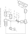
- the invention relates to a frequency-modulated continuous wave radar (FMCW radar) according to Fig. 2 , which monitors an area using digital beamforming.
- the radar sensor consists of a transmitter with several, e.g., 12 outputs (Tx) and several, e.g., 16 receivers (Rx).
- the transmitter consists of a voltage-controlled oscillator (1) with an integrated frequency modulator (2) and 12 parallel outputs (3).
- the outputs are equipped with power amplifiers (4), which can change the phase of the transmitted signal by 180° by applying a control signal (11).
- Fig. 3 shows the sawtooth-shaped temporal progression of the transmitted frequency.
- the received signal is sampled with 512 points. Approximately 256 ramps are recorded during one measurement cycle.
- the transmitted signal during each frequency ramp is binary-encoded in phase using a pseudo-random code generator. 0 means the phase is rotated by 180°, 1 means the phase remains the same.
- the pseudo-random code is preferably generated by a shift register.
- Fig. 4 shows a 3-stage shift register. Depending on the initial coding, a different code is generated.
- a process such as that described in the DE 10 2008 061 932 A1 The signal processing described above consists of a two-dimensional FFT, which generates a so-called distance-velocity matrix for each received signal.
- the antenna lobes (10) are formed. This is done by weighting, phase shifting depending on the desired viewing direction and summing the individual channels, as is the case, for example, in the DE 10 2008 061 932 A1 Alternatively, a third FFT can be calculated over the received signals, which then generates a plurality of antenna lobes in three-dimensional space, a subset of which is then used for detection in the selected field of view.
- Fig. 7 shows the antenna beam of a 16x12 antenna array. It has a beamwidth of 8° horizontally and 11° vertically and a tilt range of +- 60° in the vertical plane and +- 65° in the horizontal plane.
- Example 2 CW radar with phase encoding synchronous to the sampling frequency
- FIG. 8 shows the block diagram of this radar system.
- An oscillator (1) is operated with a monofrequency carrier signal. This signal is first divided among all 12 transmission channels (3) and phase-modulated for each channel using a binary pseudo-random code generator (4).
- the object echoes detected by the receiving antennas (5) are converted to baseband using a mixer (6) and digitized using an AD converter (7).
- the digitized signal is then cross-correlated (13) with the respective time-delayed code of the transmitter (14), generating 12 signal paths per receive channel.
- several code sequences are then accumulated (12) and then fed into a signal processing step—for example, one equivalent—consisting of 2D FFT (9) and beamforming (10).
- the maximum range in this example is 800 m, which is sufficient for automotive applications.
Landscapes
- Engineering & Computer Science (AREA)
- Radar, Positioning & Navigation (AREA)
- Remote Sensing (AREA)
- Computer Networks & Wireless Communication (AREA)
- Physics & Mathematics (AREA)
- General Physics & Mathematics (AREA)
- Electromagnetism (AREA)
- Radar Systems Or Details Thereof (AREA)
- Fittings On The Vehicle Exterior For Carrying Loads, And Devices For Holding Or Mounting Articles (AREA)
- Variable-Direction Aerials And Aerial Arrays (AREA)
- Support Of Aerials (AREA)
Description
- Die Erfindung betrifft eine Vorrichtung und ein Verfahren zur Vermessung der vertikalen und horizontalen Position von Objekten mit einem Radarsensor, welcher mit einem zweidimensionalen virtuellen Array eine digitale Stahlformung durchführt. Der Radarsensor weist dabei eine L-, U- oder inverse T-förmige Struktur auf, welche es erlaubt, dass der Sensor im Frontbereich des Automobils verbaut werden kann, ohne dass der für den Frontkühler benötigte Luftstrom wesentlich beeinträchtigt wird.
- Millimeterwellen-Radarsensoren für automobile Anwendungen, wie beispielsweise den adaptiven Tempomat sind in Fahrtrichtung im Frontbereich des Automobils verbaut. Idealerweise sollte der Sensor möglichst hoch verbaut werden, um den Einfluss des Straßenbelags auf die Ausbreitung der elektromagnetischen Welle zu minimieren. Diese Einflüsse sind Mehrwege-Ausbreitungen und Reflexionen von der Straße, welche die Objekterkennung behindern. Mehrwege-Ausbreitungen führen wegen der Überlagerung der Signale aus unterschiedlichen Richtungen zu Amplitudenschwankungen bis hin zur kurzzeitigen Auslöschung der Empfangssignale. Reflexionen von der Straßenoberfläche sog. Clutter überlagern sich mit dem gewünschten Objektsignal und reduzieren damit den Signalzu Störabstand.
- Eine erhöhte Montageposition in Verbindung mit einer zusätzlichen vertikalen Strahlschwenkung reduziert diese Einflüsse erheblich.
- Je nach Design der Karosserie, kann diese erhöhte Position jedoch nicht realisiert werden, da der für den Frontkühler benötigte Luftstrom durch eine Verbauung mit dem Radar-Sensor in nicht akzeptabler Weise beeinträchtigt wird.
- Dieser Konflikt der Anforderungen wird durch die folgende Erfindung vorteilhaft gelöst. Das Gehäuse und die Antennenanordnung des Radarsensors sind so geformt, das sie sich in die Struktur des Kühlergrills integrieren lassen. Die Antennenapertur des Radarsensors existiert dabei nur virtuell, sodass im Bereich der Antennenapertur der für die Kühlung benötigte Luftstrom ungehindert passieren kann. Das virtuelle Antennenarray erzeugt durch die numerische Verknüpfung von mehreren Sende- und Empfangseinheiten einen hochbündelnden Antennenstrahl, wie er von einem flächigem Array erzeugt würde, ohne jedoch wie dieses den Luftstrom zu beeinträchtigen.
- Eine weitere Anforderung ist die Erkennung eines Stauendes auf der Fahrbahn. Hierbei sind stehende Fahrzeuge von Brücken und Gulli-Deckeln zu unterscheiden. Ferner ist eine dreidimensionale Vermessung der Objekte zur Objektklassifikation erwünscht. Diese Aufgabe wird vorteilhaft durch eine zweidimensionale Strahlschwenkung gelöst.
- In der
DE 10 2008 052 246 A1 wird ein Sensorsystem mit verstellbarer Elevationsstrahlrichtung zur vertikalen Lagebestimmung von Objekten beschrieben. Die Verstellung erfolgt hierbei durch die mechanische Bewegung eines Reflektors. - In der Offenlegungsschrift
DE 10 2008 061 932 A1 wird ein Verfahren zur digitalen Strahlformung beschrieben.WO 2013/045232 A1 beschreibt eine Radar-Vorrichtung bei der ein zweidimensional abbildendes Radar durch Bereitstellen mehrerer Sender und mehrerer Empfänger ermöglicht wird.US 2016/282450 A1 beschreibt ein Radargerät, das eine maximal vergrößerte Aperturlänge eines virtuellen Empfangsarrays erreichen kann.EP 2 045 612 A2 beschreibt eine Erfassungs- und Entfernungsmessvorrichtung, die mehrere Sensesensoren verwendet, um die effektive Apertur eines Sensorarrays mit mehreren Sensorelementen zu vergrößern. - Aufgabe der Erfindung ist es, eine Vorrichtung und ein Verfahren zur Verfügung zu stellen, womit der oben beschriebene Verbau im Fahrzeug realisiert werden kann.
- Zusätzlich ist es Aufgabe der Erfindung eine Vorrichtung und ein Verfahren zur Verfügung zu stellen, mit dem die horizontale und vertikale Lage eines Objekts durch eine zweidimensionale Strahlformung bestimmt werden kann.
- Die Aufgabe wird vorrichtungsgemäß mit den Merkmalen des Anspruchs 1, verfahrensgemäß mit den Merkmalen des Anspruchs 5 gelöst.
- Dementsprechend umfasst die Vorrichtung eine L-, U- oder T-förmige Struktur, sodass der Luftstrom des Frontkühlers nicht oder nur gering beeinflusst wird.
- Ferner umfasst die Vorrichtung zur Bestimmung einer Position eines Objekts im dreidimensionalen Raum, insbesondere eines sich bewegenden Objekts, mindestens eine Anzahl mehrerer in Reihe angeordneter Empfangsantennen, sowie einer in Reihe angeordneten Sendeantennen, wobei die Sendeantennenreihe orthogonal zur Empfangsreihe angeordnet ist. Die beiden Antennenreihen haben bevorzugt eine T-, U- oder L-förmige Struktur (
Fig. 1a, 1b ). Die Antennen werden dabei bevorzugt als Einzel-Patch-Antennen mit breiter Strahlkeule in der horizontalen und vertikalen Richtung ausgeführt. Die Strahlbündelung und -steuerung erfolgt ausschließlich über die digitale Strahlformung durch Kombination der Einzelstrahler. Gegenüber einem hochbündelnden Einzelstrahler hat dies den Vorteil, dass beim digital geformten Strahl die Struktur eines Kühlergrills die Antennenrichtcharakteristik nur gering beeinflusst. - Ferner umfasst die Vorrichtung einen Frequenzgenerator zur Erzeugung eines Signals, welches individuell für jede Sende-Antenne phasencodiert wird. Zur Formung eines virtuellen zweidimensionalen Arrays sind jeweils eine Sendeantenne und eine Empfangsantenne zu kombinieren. Das Signal der Empfangsantennen wird zunächst mit dem gemeinsamen uncodierten Sendesignal in eine Zwischenfrequenzebene oder in das Basisband umgesetzt. Anschließend erfolgt eine analoge Signalaufbereitung (Filterung, Verstärkung) und eine Digitalisierung der Signale. Das Signal wird dann mit dem Code des gewünschten Sende-Partners decodiert und das virtuelle zweidimensionale Array erzeugt.
- Ferner sind die Sender zeitgleich zu betreiben, damit das Verfahren der digitalen Strahlformung auch bei hochdynamischen Szenarien, wie dem Straßenverkehr einsetzbar ist.
- Nachfolgend werden Ausführungsbeispiele der Erfindung anhand einer Zeichnung näher erläutert. Einander entsprechende Teile sind in allen Figuren mit den gleichen Bezugszeichen versehen.
- Die Erfindung betrifft ein frequenzmoduliertes Dauerstrich Radar (FMCW-Radar) nach
Fig. 2 , welches ein Gebiet mit Hilfe der digitalen Strahlformung überwacht. Der Radarsensor besteht dabei aus einem Sender mit mehreren z.B. 12 Ausgängen (Tx) und mehreren z.B. 16 Empfängern (Rx). Der Sender besteht aus einem spannungsgesteuerten Oszillator (1) mit integriertem Frequenzmodulator (2) und 12 parallelen Ausgängen (3). Die Ausgänge sind dabei mit Endverstärkern (4) bestückt, welche durch Anlegen eines Steuersignals (11) die Phase des Sendesignals um 180° verändern können. -
Fig. 3 zeigt den sägezahnförmigen zeitlichen Verlauf der Sendefrequenz. Während einer Frequenzrampe wird das Empfangssignal beispielsweise mit 512 Punkten abgetastet. Es werden ca. 256 Rampen während eines Messzyklus aufgezeichnet. - Das Sendesignal während der einzelnen Frequenzrampen wird mit Hilfe eines sog. Pseudo-Random-Code-Generators in der Phase binär codiert. O bedeutet die Phase wird um 180° gedreht, 1 bedeutet die Phase bleibt gleich.
- Der Pseudo-Random-Code wird bevorzugt durch ein Schieberegister erzeugt.
Fig. 4 zeigt ein 3-stufiges Schieberegister. Je nach Anfangscodierung stellt sich ein unterschiedlicher Code ein. Die Codelänge berechnet sich zu
N = 2n - 1, mit n = Anzahl der Registerstufen. Bei dem hier dargestellten Register mit 3 Stufen, wiederholt sich der Code also nach 7 Zeit-Stufen. In der Praxis werden jedoch längere Codes bevorzugt, da hier die Entkopplung zwischen den einzelnen Sendesignalen besser ist. - Im Empfänger des Radarsensors nach
Fig. 2 wird das vom Objekt reflektierte und von der Antenne (5) empfangene Signal zunächst mit einem Mischer (6) in das Basisband umgesetzt und von einem AD-Wandler (7) abgetastet. Das abgetastete Signal wird dann mit den Codes der jeweiligen Sender dekodiert (8). So entstehen bei 16 Empfängern und 12 Transmittern 12*16= 192 Empfangssignale. Diese Signale können dem inFig. 5 dargestellten Elementen des virtuellen Arrays zugeordnet werden. - Nach der Dekodierung erfolgt eine wie beispielsweise in der
DE 10 2008 061 932 A1 beschriebene Signalverarbeitung. Diese besteht zunächst aus einer zweidimensionalen FFT, welche eine sog. Entfernungs-Geschwindigkeits-Matrix je Empfangssignal erzeugt.Fig. 6 zeigt beispielhaft eine solche Matrix mit einem Echosignal bei Entfernungszelle 100 und Geschwindigkeitszelle 0. Durch die endliche Entkopplung zwischen den einzelnen Sendecodes, entstehen Nebenlinien in Geschwindigkeitsrichtung, welche bei der hier gewählten Codelänge N = 255 circa 20 dB unterhalb des Nutzsignals liegen. Der Dynamik-Bereich in Geschwindigkeitsrichtung ist also eingeschränkt. Der Dynamik-Bereich in Entfernungsrichtung ist davon nicht betroffen. Dies bedeutet, dass beispielsweise Objekte bei gleicher Entfernung aber mit unterschiedlicher Geschwindigkeit sich in der Echo-Amplitude um weniger als 20 dB unterscheiden müssen, um noch separat erkannt zu werden. - Nach der zweidimensionalen FFT (9) werden die Antennenkeulen (10) geformt. Dies geschieht durch eine Gewichtung, Phasenverschiebung je nach gewünschter Blickrichtung und Aufsummierung der einzelnen Kanäle, wie es z.B. in der
DE 10 2008 061 932 A1 beschrieben ist. Alternativ kann eine dritte FFT über die Empfangssignale gerechnet werden, welche dann eine Vielzahl von Antennenkeulen im dreidimensionalen Raum erzeugt, von denen dann eine Untermenge für die Detektion im gewählten Blickfeld herangezogen wird.Fig. 7 zeigt die Antennenkeule eines 16x12 Antennenarrays. Sie hat eine Strahlbreite von 8° horizontal und 11° vertikal und einen Schwenkbereich von +- 60° in der vertikalen sowie von +- 65° in der horizontalen Ebene. - Ein weiteres Ausführungsbeispiel ist eine binäre Phasencodierung eines monofrequenten Dauerstrich-Signals (sog. CW-Signal).
Fig. 8 zeigt das Blockschaltbild dieses Radarsystems. Ein Oszillator (1) wird mit einem monofrequenten Trägersignal betrieben. Dieses Signal wird zunächst auf alle 12 Sendekanäle (3) aufgeteilt und je Kanal in der Phase binär durch einen "pseudo-random" Codegenerator (4) moduliert. Die von den Empfangsantennen (5) erfassten Objekt-Echos werden mit einem Mischer (6) in das Basisband umgesetzt und mit einem AD-Wandler (7) digitalisiert. Anschließend erfolgt eine Kreuzkorrelation (13) des digitalisierten Signals mit dem jeweiligen zeitverzögerten Code des Senders (14), sodass 12 Signalpfade je Empfangskanal generiert werden. Zur Verbesserung des Signal-Rauschabstandes werden dann mehrere Code-Sequenzen akkumuliert (12) und dann einer - zum Beispiel 1 äquivalenten - Signalverarbeitung, bestehend aus 2D-FFT (9) und Beamforming (10) zugeführt. - Im Gegensatz zu der relativ langsamen Phasencodierung nach Beispiel 1, wird hier die Phase eines monofrequenten Signals mit jedem Abtastwert geändert. Für die sog. Chip-Länge Tc gilt: Tc = 2*ΔR/c mit
- ΔR: Entfernungsauflösung
- c: Lichtgeschwindigkeit
- Will man also eine Auflösung von 10 cm erreichen, so ist eine Chip-Länge von 0.67 nsec und eine Abtastfrequenz von 1.5 Gigasamples/sec. nötig. Bei einer Codelänge von 213 -1 = 8192 ist die Dauer des Codes Lc = 5.46 µs. Die Code-Dauer bestimmt die maximal eindeutige Reichweite. Es gilt Lc = 2*Rmax/c.
- Die maximale Reichweite beträgt also in diesem Beispiel 800 m, was für die Anwendung im Automobilbereich ausreichend ist.
Claims (9)
- Vorrichtung zur Bestimmung der Position eines Objekts im dreidimensionalen Raum mittels einer Antennenstruktur (5), wobei die Antennenstruktur eine L-, U- oder T-förmige Struktur aufweist und im Bereich des Front-Kühlers mit Kühlergrill eines Fahrzeugs montierbar ist, wobei die Antennenstruktur ein Radarsensor ist und ein Gehäuse und eine Antennenordnung des Radarsensors derart geformt sind, dass sie in die Struktur des Kühlergrills integrierbar sind, wobei die Antennenstruktur hinter dem luftundurchlässigen Bereich des Kühlergrills vorgesehen ist und wobei eine kombinierte Frequenz-Phasenmodulation der Sendesignale und gleichzeitiger Betrieb aller Sender ermöglicht wird.
- Vorrichtung nach Anspruch 1, wobei die Antennenstruktur (5) mehrere Radar-Sende-/Empfangs-Einrichtungen aufweist, wobei jede Einrichtung eine Vielzahl von Empfängern und eine Vielzahl von Sendern aufweist, und ein virtuelles Antennenarray für zweidimensionale horizontale und vertikale Strahlschwenkung bildet, wobei das virtuelle Antennenarray im Bereich der Lüftungsöffnungen des Kühlergrills zum Liegen kommt.
- Vorrichtung nach einem der Ansprüche 1 bis 2, wobei eine Auswerteeinheit vorgesehen ist, welche mit festgelegten Sendecodes das in der EmpfangsEinrichtung eingegangene Empfangssignal decodiert (8), sodass aus einem Empfangssignal eine Vielzahl von Subsignale erzeugt wird, deren Vielzahl der Anzahl der Sender entspricht.
- Vorrichtung nach einem der Ansprüche 1 bis 3, wobei eine hochfrequente Phasenmodulation des Dauerstrich-Sendesignals und gleichzeitigem Betrieb aller Sender vorgesehen und wobei eine binäre 180° Phasencodierung vorgesehen ist, welche durch einen Pseudo-Zufallszahlen-Generator erzeugt wird.
- Verfahren zur Bestimmung einer Position eines Objektes, unter Verwendung einer Vorrichtung nach einem der Ansprüche 1 bis 4, mit folgenden Verfahrensschritten:a. Senden und Empfangen von Signalen mit Hilfe von Antennenstruktur in L- oder T-förmiger Anordnung, welche hinter dem luftundurchlässigen Bereich des Kühlergrills eines Fahrzeuges montiert wirdb. Erzeugen einer Code-Folge für die Sender nach dem Pseudo-Zufallsprinzip mit Hilfe eines rückgekoppelten Schieberegisters.c. Erzeugen von Subsignalen aus dem Empfangssignal mittels De-Codierungsverfahrend. Zuordnen der einzelnen Subsignale zu den Einzelstrahlern eines durch die Antennenstruktur erzeugten virtuellen Arraysstruktur.e. Verknüpfen der Subsignale nach der Methode der digitalen Strahlformung zu mehreren gebündelten Antennenstrahlen in der horizontalen und vertikalen Richtungf. Darstellen der horizontalen und vertikalen Position des Objekts.
- Verfahren nach Anspruch 5, wobei mittels sägezahnförmiger Frequenzmodulation (2) des Sendesignals eine binäre 0°/180°-Phasencodierung des Sendesignals von Frequenzrampe zu Frequenzrampe vorgesehen ist.
- Verfahren nach Anspruch 5 oder 6, wobei das De-Codierungsverfahren durch die Decodierung (8) mit der individuell erzeugten Code-Folge der Sendeantennen erfolgt.
- Verfahren nach Anspruch 5, wobei eine hochfrequente binäre Phasenmodulation eines Dauerstrich-Sendesignals vorgesehen ist.
- Verfahren nach einem der Ansprüche 5 oder 8, das De-Codierungsverfahren durch Kreuzkorrelation mit der zeitverzögerten individuell erzeugten Code-Folge der Sendeantennen erfolgt.
Applications Claiming Priority (2)
| Application Number | Priority Date | Filing Date | Title |
|---|---|---|---|
| DE102017200383.9A DE102017200383A1 (de) | 2017-01-11 | 2017-01-11 | Radarsensor mit zweidimensionaler Strahlschwenkung und L-, U- oder T-förmiger Struktur für den Verbau im Bereich des Front-Kühlers beim Automobil |
| PCT/EP2017/082619 WO2018130364A1 (de) | 2017-01-11 | 2017-12-13 | Radarsensor mit zweidimensionaler strahlschwenkung und l-, u- oder t-förmiger struktur für den verbau im bereich des front-kühlers beim automobil |
Publications (2)
| Publication Number | Publication Date |
|---|---|
| EP3568713A1 EP3568713A1 (de) | 2019-11-20 |
| EP3568713B1 true EP3568713B1 (de) | 2025-04-23 |
Family
ID=60702754
Family Applications (1)
| Application Number | Title | Priority Date | Filing Date |
|---|---|---|---|
| EP17816758.1A Active EP3568713B1 (de) | 2017-01-11 | 2017-12-13 | Radarsensor mit zweidimensionaler strahlschwenkung und l-, u- oder t-förmiger struktur für den verbau im bereich des front-kühlers beim automobil |
Country Status (7)
| Country | Link |
|---|---|
| US (1) | US11740349B2 (de) |
| EP (1) | EP3568713B1 (de) |
| JP (1) | JP7139334B2 (de) |
| KR (1) | KR20190100358A (de) |
| CN (1) | CN110235021B (de) |
| DE (1) | DE102017200383A1 (de) |
| WO (1) | WO2018130364A1 (de) |
Families Citing this family (10)
| Publication number | Priority date | Publication date | Assignee | Title |
|---|---|---|---|---|
| US20180287432A1 (en) * | 2017-03-29 | 2018-10-04 | Qualcomm Incorporated | Adaptive adc control for living object protection |
| JP7224174B2 (ja) * | 2018-12-26 | 2023-02-17 | ルネサスエレクトロニクス株式会社 | 電子装置およびレーダー制御方法 |
| EP4042200A4 (de) * | 2019-11-08 | 2024-02-07 | Vayyar Imaging Ltd. | Systeme und verfahren zur erfassung der umgebung eines fahrzeugs |
| CN110843713A (zh) * | 2019-11-27 | 2020-02-28 | 青岛双星轮胎工业有限公司 | 汽车进气格栅装置 |
| EP4062555A4 (de) * | 2019-12-31 | 2024-05-08 | Vayyar Imaging Ltd | Systeme und verfahren zur formung von durch antennenanordnungen erzeugten strahlen |
| JP7003345B2 (ja) * | 2020-01-15 | 2022-01-20 | 三菱電機株式会社 | レーダ装置、レーダ運用方法、及び、レーダ運用プログラム |
| US11860263B2 (en) * | 2020-12-29 | 2024-01-02 | GM Global Technology Operations LLC | Variable code sequences for radar transmission |
| US20240036175A1 (en) * | 2022-07-27 | 2024-02-01 | Baidu Usa Llc | Single photon detection based light detection and range (lidar) for autonomous driving vehicles |
| CN116388830B (zh) * | 2023-05-19 | 2026-04-03 | 东南大学 | 基于智能反射面的通信定位一体化系统及方法 |
| DE102024124891A1 (de) * | 2024-08-30 | 2026-03-05 | Hensoldt Sensors Gmbh | Steuervorrichtung, antennenarray und verfahren zum ansteuern eines antennenarrays |
Citations (1)
| Publication number | Priority date | Publication date | Assignee | Title |
|---|---|---|---|---|
| DE112014004880T5 (de) * | 2013-10-24 | 2016-07-07 | Toyota Jidosha Kabushiki Kaisha | Dekorativer Beschichtungsfilm |
Family Cites Families (30)
| Publication number | Priority date | Publication date | Assignee | Title |
|---|---|---|---|---|
| DE19844021C2 (de) * | 1998-09-25 | 2001-05-10 | Daimler Chrysler Ag | Innerhalb des Strahlenganges eines Radargerätes liegendes Verkleidungsteil |
| US6121919A (en) * | 1999-07-23 | 2000-09-19 | Eaton-Vorad Technologies, L.L.C. | Method and apparatus for range correction in a radar system |
| JP4331152B2 (ja) * | 2005-09-20 | 2009-09-16 | 本田技研工業株式会社 | 物体検知装置の取付構造 |
| JP2009080024A (ja) * | 2007-09-26 | 2009-04-16 | Fujitsu Ltd | 探知測距装置および探知測距方法 |
| JP5371277B2 (ja) * | 2008-03-31 | 2013-12-18 | 三菱電機株式会社 | レーダ装置 |
| DE102008052246A1 (de) | 2008-10-18 | 2010-04-22 | Adc Automotive Distance Control Systems Gmbh | Sensorsystem mit verstellbarer Elevationsstrahlrichtung zur Bestimmung der vertikalen Lage von stationären Objekten |
| DE102008061932A1 (de) | 2008-12-12 | 2010-07-01 | Astyx Gmbh | Abbildender Radarsensor mit digitaler Strahlformung und synthetischer Vergrößerung der Antennenapertur |
| DE102010063665A1 (de) * | 2010-12-21 | 2012-06-21 | Siemens Aktiengesellschaft | Verfahren zur Positionierung eines Elektroautos relativ zu einer Ladestation |
| DE102011083756A1 (de) * | 2011-09-29 | 2013-04-04 | Siemens Ag | Radar-Vorrichtung und Verfahren zum Erzeugen einer Gruppencharakteristik eines Radars |
| JP6192910B2 (ja) * | 2012-09-04 | 2017-09-06 | 富士通テン株式会社 | レーダ装置および物標高算出方法 |
| JP2014069634A (ja) * | 2012-09-28 | 2014-04-21 | Toyoda Gosei Co Ltd | 車両用加飾部材 |
| DE102013210256A1 (de) * | 2013-06-03 | 2014-12-04 | Robert Bosch Gmbh | Interferenzunterdrückung bei einem fmcw-radar |
| JP2015099081A (ja) * | 2013-11-19 | 2015-05-28 | 豊田合成株式会社 | 電波透過カバー及び電波透過カバーの製造方法 |
| DE102014200690A1 (de) * | 2014-01-16 | 2015-07-16 | Robert Bosch Gmbh | Antennenanordnung, radarsystem, fahrzeug und verfahren |
| DE102014208899A1 (de) * | 2014-05-12 | 2015-11-12 | Robert Bosch Gmbh | Verfahren zur Kalibrierung eines MIMO-Radarsensors für Kraftfahrzeuge |
| EP2963442B1 (de) * | 2014-07-04 | 2016-11-30 | Denso Corporation | Radarvorrichtung |
| US9733340B2 (en) * | 2014-11-21 | 2017-08-15 | Texas Instruments Incorporated | Techniques for high arrival angle resolution using multiple nano-radars |
| JP6377000B2 (ja) * | 2015-03-25 | 2018-08-22 | パナソニック株式会社 | レーダ装置 |
| DE102015006287A1 (de) * | 2015-05-15 | 2015-12-03 | Daimler Ag | Kraftfahrzeug |
| US20170023674A1 (en) * | 2015-07-20 | 2017-01-26 | Ford Global Technologies, Llc | Vehicular radar adjustment mechanism |
| US10351077B2 (en) * | 2015-08-25 | 2019-07-16 | Mazda Motor Corporation | Vehicle member |
| CN106546983B (zh) * | 2015-09-17 | 2021-11-12 | 松下电器产业株式会社 | 雷达装置 |
| US10571562B2 (en) * | 2016-03-25 | 2020-02-25 | Magna Electronics Inc. | Vehicle short range sensing system using RF sensors |
| US9575160B1 (en) * | 2016-04-25 | 2017-02-21 | Uhnder, Inc. | Vehicular radar sensing system utilizing high rate true random number generator |
| US10534081B2 (en) * | 2016-05-02 | 2020-01-14 | Magna Electronics Inc. | Mounting system for vehicle short range sensors |
| WO2017211419A1 (en) * | 2016-06-09 | 2017-12-14 | Zanini Auto Grup, S.A. | Radome for vehicles |
| US10677894B2 (en) * | 2016-09-06 | 2020-06-09 | Magna Electronics Inc. | Vehicle sensing system for classification of vehicle model |
| WO2018074118A1 (ja) * | 2016-10-21 | 2018-04-26 | 豊田合成 株式会社 | 車両用装飾部品及びその製造方法 |
| KR102647693B1 (ko) * | 2016-11-28 | 2024-03-15 | 주식회사 에이치엘클레무브 | 레이더 장치 및 그의 오차 보정 방법 |
| DE102017200273A1 (de) * | 2017-01-10 | 2018-07-12 | Audi Ag | Radaranordnung für ein Kraftfahrzeug und Kraftfahrzeug |
-
2017
- 2017-01-11 DE DE102017200383.9A patent/DE102017200383A1/de not_active Withdrawn
- 2017-12-13 JP JP2019536170A patent/JP7139334B2/ja active Active
- 2017-12-13 US US16/476,658 patent/US11740349B2/en active Active
- 2017-12-13 CN CN201780083087.5A patent/CN110235021B/zh active Active
- 2017-12-13 EP EP17816758.1A patent/EP3568713B1/de active Active
- 2017-12-13 KR KR1020197022283A patent/KR20190100358A/ko not_active Abandoned
- 2017-12-13 WO PCT/EP2017/082619 patent/WO2018130364A1/de not_active Ceased
Patent Citations (1)
| Publication number | Priority date | Publication date | Assignee | Title |
|---|---|---|---|---|
| DE112014004880T5 (de) * | 2013-10-24 | 2016-07-07 | Toyota Jidosha Kabushiki Kaisha | Dekorativer Beschichtungsfilm |
Also Published As
| Publication number | Publication date |
|---|---|
| EP3568713A1 (de) | 2019-11-20 |
| US11740349B2 (en) | 2023-08-29 |
| KR20190100358A (ko) | 2019-08-28 |
| JP2020506836A (ja) | 2020-03-05 |
| DE102017200383A1 (de) | 2018-07-12 |
| CN110235021B (zh) | 2023-06-30 |
| CN110235021A (zh) | 2019-09-13 |
| WO2018130364A1 (de) | 2018-07-19 |
| JP7139334B2 (ja) | 2022-09-20 |
| US20190377083A1 (en) | 2019-12-12 |
Similar Documents
| Publication | Publication Date | Title |
|---|---|---|
| EP3568713A1 (de) | Radarsensor mit zweidimensionaler strahlschwenkung und l-, u- oder t-förmiger struktur für den verbau im bereich des front-kühlers beim automobil | |
| EP2753950B1 (de) | Abbildender radarsensor mit synthetischer vergrösserung der antennenapertur und zweidimensionaler strahlschwenkung | |
| US12055620B2 (en) | Imaging radar system having an offset receiving array for determining the angle of an object | |
| WO2004061475A1 (de) | Winkelauflösendes antennensystem | |
| EP3227719A1 (de) | Radarsensor, radarsensor-system sowie verfahren zur bestimmung der position eines objekts mit horizontaler und vertikaler digitaler strahlformung zur vermessung von punkt- und flächenförmig reflektierenden objekten | |
| DE102011113018A1 (de) | Abbildender Radarsensor mit schmaler Antennenkeule und weitem Winkel-Detektionsbereich | |
| DE102011083756A1 (de) | Radar-Vorrichtung und Verfahren zum Erzeugen einer Gruppencharakteristik eines Radars | |
| US10989799B2 (en) | Radar and antenna built in radar | |
| DE102008054228A1 (de) | Fahrzeugseitige Richtungserkennungsvorrichtung zur genauen Erkennung von Zielkörperrichtungen ungeachtet der Fahrgeschwindigkeit | |
| EP3452847B1 (de) | Kraftfahrzeug mit wenigstens zwei radarsensoren | |
| DE102006022814A1 (de) | Hochauflösendes Synthetik-Apertur-Seitenansicht-Radarsystem mittels Digital Beamforming | |
| DE10258367A1 (de) | Mehrzielfähiges Verfahren und mehrzielfähige Sensorvorrichtung für die Abstands- und Winkelortung von Zielobjekten im Nahbereich | |
| WO2010066458A1 (de) | Abbildender radarsensor mit digitaler strahlformung und synthetischer vergrösserung der antennenapertur | |
| DE102009047561A1 (de) | Antenneneinrichtung für eine Radarsensorvorrichtung | |
| EP1431773A2 (de) | Winkelscannendes Radarsystem | |
| DE102004034429B4 (de) | Radar Front-End | |
| WO2009077236A1 (de) | Monostatischer mehrstrahl-radarsensor, sowie verfahren | |
| DE102008034572B4 (de) | Empfangsvorrichtung | |
| EP3803443A1 (de) | Polarimetrisches radar sowie eine geeignete verwendung und verfahren hierfür | |
| DE102018209131A1 (de) | Polarimetrisches Radar sowie eine geeignete Verwendung und Verfahren hierfür | |
| WO2018130402A1 (de) | Radaranordnung für ein kraftfahrzeug und kraftfahrzeug | |
| DE102004044067A1 (de) | Vorrichtung und Verfahren zum Detektieren von Objekten im Bereich eines Fahrzeugs |
Legal Events
| Date | Code | Title | Description |
|---|---|---|---|
| STAA | Information on the status of an ep patent application or granted ep patent |
Free format text: STATUS: UNKNOWN |
|
| STAA | Information on the status of an ep patent application or granted ep patent |
Free format text: STATUS: THE INTERNATIONAL PUBLICATION HAS BEEN MADE |
|
| PUAI | Public reference made under article 153(3) epc to a published international application that has entered the european phase |
Free format text: ORIGINAL CODE: 0009012 |
|
| STAA | Information on the status of an ep patent application or granted ep patent |
Free format text: STATUS: REQUEST FOR EXAMINATION WAS MADE |
|
| 17P | Request for examination filed |
Effective date: 20190805 |
|
| AK | Designated contracting states |
Kind code of ref document: A1 Designated state(s): AL AT BE BG CH CY CZ DE DK EE ES FI FR GB GR HR HU IE IS IT LI LT LU LV MC MK MT NL NO PL PT RO RS SE SI SK SM TR |
|
| AX | Request for extension of the european patent |
Extension state: BA ME |
|
| DAV | Request for validation of the european patent (deleted) | ||
| DAX | Request for extension of the european patent (deleted) | ||
| STAA | Information on the status of an ep patent application or granted ep patent |
Free format text: STATUS: EXAMINATION IS IN PROGRESS |
|
| 17Q | First examination report despatched |
Effective date: 20220214 |
|
| P01 | Opt-out of the competence of the unified patent court (upc) registered |
Effective date: 20230525 |
|
| REG | Reference to a national code |
Ref legal event code: R079 Free format text: PREVIOUS MAIN CLASS: G01S0013930000 Ref country code: DE Ref document number: 502017016812 Country of ref document: DE Ipc: G01S0013931000 |
|
| GRAP | Despatch of communication of intention to grant a patent |
Free format text: ORIGINAL CODE: EPIDOSNIGR1 |
|
| STAA | Information on the status of an ep patent application or granted ep patent |
Free format text: STATUS: GRANT OF PATENT IS INTENDED |
|
| RIC1 | Information provided on ipc code assigned before grant |
Ipc: G01S 13/34 20060101ALI20250130BHEP Ipc: G01S 13/32 20060101ALI20250130BHEP Ipc: G01S 7/02 20060101ALI20250130BHEP Ipc: G01S 13/93 20060101ALI20250130BHEP Ipc: G01S 13/931 20200101AFI20250130BHEP |
|
| INTG | Intention to grant announced |
Effective date: 20250210 |
|
| GRAS | Grant fee paid |
Free format text: ORIGINAL CODE: EPIDOSNIGR3 |
|
| GRAA | (expected) grant |
Free format text: ORIGINAL CODE: 0009210 |
|
| STAA | Information on the status of an ep patent application or granted ep patent |
Free format text: STATUS: THE PATENT HAS BEEN GRANTED |
|
| AK | Designated contracting states |
Kind code of ref document: B1 Designated state(s): AL AT BE BG CH CY CZ DE DK EE ES FI FR GB GR HR HU IE IS IT LI LT LU LV MC MK MT NL NO PL PT RO RS SE SI SK SM TR |
|
| REG | Reference to a national code |
Ref country code: GB Ref legal event code: FG4D Free format text: NOT ENGLISH |
|
| REG | Reference to a national code |
Ref country code: CH Ref legal event code: EP |
|
| REG | Reference to a national code |
Ref country code: DE Ref legal event code: R096 Ref document number: 502017016812 Country of ref document: DE |
|
| REG | Reference to a national code |
Ref country code: IE Ref legal event code: FG4D Free format text: LANGUAGE OF EP DOCUMENT: GERMAN |
|
| RAP4 | Party data changed (patent owner data changed or rights of a patent transferred) |
Owner name: CRUISE MUNICH GMBH |
|
| REG | Reference to a national code |
Ref country code: DE Ref legal event code: R081 Ref document number: 502017016812 Country of ref document: DE Owner name: ASTYX GMBH, DE Free format text: FORMER OWNER: ANMELDERANGABEN UNKLAR / UNVOLLSTAENDIG, 80297 MUENCHEN, DE Ref country code: DE Ref legal event code: R081 Ref document number: 502017016812 Country of ref document: DE Owner name: CRUISE MUNICH GMBH, DE Free format text: FORMER OWNER: ANMELDERANGABEN UNKLAR / UNVOLLSTAENDIG, 80297 MUENCHEN, DE |
|
| REG | Reference to a national code |
Ref country code: DE Ref legal event code: R081 Ref document number: 502017016812 Country of ref document: DE Owner name: CRUISE MUNICH GMBH, DE Free format text: FORMER OWNER: ASTYX GMBH, 85521 OTTOBRUNN, DE |
|
| REG | Reference to a national code |
Ref country code: NL Ref legal event code: MP Effective date: 20250423 |
|
| PG25 | Lapsed in a contracting state [announced via postgrant information from national office to epo] |
Ref country code: NL Free format text: LAPSE BECAUSE OF FAILURE TO SUBMIT A TRANSLATION OF THE DESCRIPTION OR TO PAY THE FEE WITHIN THE PRESCRIBED TIME-LIMIT Effective date: 20250423 |
|
| PG25 | Lapsed in a contracting state [announced via postgrant information from national office to epo] |
Ref country code: PT Free format text: LAPSE BECAUSE OF FAILURE TO SUBMIT A TRANSLATION OF THE DESCRIPTION OR TO PAY THE FEE WITHIN THE PRESCRIBED TIME-LIMIT Effective date: 20250825 Ref country code: FI Free format text: LAPSE BECAUSE OF FAILURE TO SUBMIT A TRANSLATION OF THE DESCRIPTION OR TO PAY THE FEE WITHIN THE PRESCRIBED TIME-LIMIT Effective date: 20250423 Ref country code: ES Free format text: LAPSE BECAUSE OF FAILURE TO SUBMIT A TRANSLATION OF THE DESCRIPTION OR TO PAY THE FEE WITHIN THE PRESCRIBED TIME-LIMIT Effective date: 20250423 |
|
| REG | Reference to a national code |
Ref country code: LT Ref legal event code: MG9D |
|
| PG25 | Lapsed in a contracting state [announced via postgrant information from national office to epo] |
Ref country code: NO Free format text: LAPSE BECAUSE OF FAILURE TO SUBMIT A TRANSLATION OF THE DESCRIPTION OR TO PAY THE FEE WITHIN THE PRESCRIBED TIME-LIMIT Effective date: 20250723 Ref country code: GR Free format text: LAPSE BECAUSE OF FAILURE TO SUBMIT A TRANSLATION OF THE DESCRIPTION OR TO PAY THE FEE WITHIN THE PRESCRIBED TIME-LIMIT Effective date: 20250724 |
|
| PG25 | Lapsed in a contracting state [announced via postgrant information from national office to epo] |
Ref country code: PL Free format text: LAPSE BECAUSE OF FAILURE TO SUBMIT A TRANSLATION OF THE DESCRIPTION OR TO PAY THE FEE WITHIN THE PRESCRIBED TIME-LIMIT Effective date: 20250423 |
|
| PG25 | Lapsed in a contracting state [announced via postgrant information from national office to epo] |
Ref country code: BG Free format text: LAPSE BECAUSE OF FAILURE TO SUBMIT A TRANSLATION OF THE DESCRIPTION OR TO PAY THE FEE WITHIN THE PRESCRIBED TIME-LIMIT Effective date: 20250423 |
|
| PG25 | Lapsed in a contracting state [announced via postgrant information from national office to epo] |
Ref country code: HR Free format text: LAPSE BECAUSE OF FAILURE TO SUBMIT A TRANSLATION OF THE DESCRIPTION OR TO PAY THE FEE WITHIN THE PRESCRIBED TIME-LIMIT Effective date: 20250423 |
|
| PG25 | Lapsed in a contracting state [announced via postgrant information from national office to epo] |
Ref country code: RS Free format text: LAPSE BECAUSE OF FAILURE TO SUBMIT A TRANSLATION OF THE DESCRIPTION OR TO PAY THE FEE WITHIN THE PRESCRIBED TIME-LIMIT Effective date: 20250723 |
|
| PG25 | Lapsed in a contracting state [announced via postgrant information from national office to epo] |
Ref country code: IS Free format text: LAPSE BECAUSE OF FAILURE TO SUBMIT A TRANSLATION OF THE DESCRIPTION OR TO PAY THE FEE WITHIN THE PRESCRIBED TIME-LIMIT Effective date: 20250823 |
|
| PG25 | Lapsed in a contracting state [announced via postgrant information from national office to epo] |
Ref country code: LV Free format text: LAPSE BECAUSE OF FAILURE TO SUBMIT A TRANSLATION OF THE DESCRIPTION OR TO PAY THE FEE WITHIN THE PRESCRIBED TIME-LIMIT Effective date: 20250423 |
|
| PG25 | Lapsed in a contracting state [announced via postgrant information from national office to epo] |
Ref country code: SM Free format text: LAPSE BECAUSE OF FAILURE TO SUBMIT A TRANSLATION OF THE DESCRIPTION OR TO PAY THE FEE WITHIN THE PRESCRIBED TIME-LIMIT Effective date: 20250423 Ref country code: DK Free format text: LAPSE BECAUSE OF FAILURE TO SUBMIT A TRANSLATION OF THE DESCRIPTION OR TO PAY THE FEE WITHIN THE PRESCRIBED TIME-LIMIT Effective date: 20250423 |
|
| PG25 | Lapsed in a contracting state [announced via postgrant information from national office to epo] |
Ref country code: CZ Free format text: LAPSE BECAUSE OF FAILURE TO SUBMIT A TRANSLATION OF THE DESCRIPTION OR TO PAY THE FEE WITHIN THE PRESCRIBED TIME-LIMIT Effective date: 20250423 |
|
| PG25 | Lapsed in a contracting state [announced via postgrant information from national office to epo] |
Ref country code: EE Free format text: LAPSE BECAUSE OF FAILURE TO SUBMIT A TRANSLATION OF THE DESCRIPTION OR TO PAY THE FEE WITHIN THE PRESCRIBED TIME-LIMIT Effective date: 20250423 |
|
| REG | Reference to a national code |
Ref country code: DE Ref legal event code: R097 Ref document number: 502017016812 Country of ref document: DE |
|
| PG25 | Lapsed in a contracting state [announced via postgrant information from national office to epo] |
Ref country code: SK Free format text: LAPSE BECAUSE OF FAILURE TO SUBMIT A TRANSLATION OF THE DESCRIPTION OR TO PAY THE FEE WITHIN THE PRESCRIBED TIME-LIMIT Effective date: 20250423 Ref country code: RO Free format text: LAPSE BECAUSE OF FAILURE TO SUBMIT A TRANSLATION OF THE DESCRIPTION OR TO PAY THE FEE WITHIN THE PRESCRIBED TIME-LIMIT Effective date: 20250423 |
|
| PG25 | Lapsed in a contracting state [announced via postgrant information from national office to epo] |
Ref country code: IT Free format text: LAPSE BECAUSE OF FAILURE TO SUBMIT A TRANSLATION OF THE DESCRIPTION OR TO PAY THE FEE WITHIN THE PRESCRIBED TIME-LIMIT Effective date: 20250423 |
|
| PLBE | No opposition filed within time limit |
Free format text: ORIGINAL CODE: 0009261 |
|
| STAA | Information on the status of an ep patent application or granted ep patent |
Free format text: STATUS: NO OPPOSITION FILED WITHIN TIME LIMIT |
|
| REG | Reference to a national code |
Ref country code: CH Ref legal event code: L10 Free format text: ST27 STATUS EVENT CODE: U-0-0-L10-L00 (AS PROVIDED BY THE NATIONAL OFFICE) Effective date: 20260304 |
|
| 26N | No opposition filed |
Effective date: 20260126 |