EP3567381B1 - Flexible jaw probe for non-contact electrical parameter measurement - Google Patents
Flexible jaw probe for non-contact electrical parameter measurement Download PDFInfo
- Publication number
- EP3567381B1 EP3567381B1 EP19173650.3A EP19173650A EP3567381B1 EP 3567381 B1 EP3567381 B1 EP 3567381B1 EP 19173650 A EP19173650 A EP 19173650A EP 3567381 B1 EP3567381 B1 EP 3567381B1
- Authority
- EP
- European Patent Office
- Prior art keywords
- sensor
- electrical parameter
- flexible arm
- contact
- sensor probe
- Prior art date
- Legal status (The legal status is an assumption and is not a legal conclusion. Google has not performed a legal analysis and makes no representation as to the accuracy of the status listed.)
- Active
Links
Images

Classifications
-
- G—PHYSICS
- G01—MEASURING; TESTING
- G01R—MEASURING ELECTRIC VARIABLES; MEASURING MAGNETIC VARIABLES
- G01R15/00—Details of measuring arrangements of the types provided for in groups G01R17/00 - G01R29/00, G01R33/00 - G01R33/26 or G01R35/00
- G01R15/14—Adaptations providing voltage or current isolation, e.g. for high-voltage or high-current networks
- G01R15/18—Adaptations providing voltage or current isolation, e.g. for high-voltage or high-current networks using inductive devices, e.g. transformers
- G01R15/186—Adaptations providing voltage or current isolation, e.g. for high-voltage or high-current networks using inductive devices, e.g. transformers using current transformers with a core consisting of two or more parts, e.g. clamp-on type
-
- G—PHYSICS
- G01—MEASURING; TESTING
- G01R—MEASURING ELECTRIC VARIABLES; MEASURING MAGNETIC VARIABLES
- G01R1/00—Details of instruments or arrangements of the types included in groups G01R5/00 - G01R13/00 and G01R31/00
- G01R1/02—General constructional details
- G01R1/04—Housings; Supporting members; Arrangements of terminals
- G01R1/0408—Test fixtures or contact fields; Connectors or connecting adaptors; Test clips; Test sockets
- G01R1/0416—Connectors, terminals
-
- G—PHYSICS
- G01—MEASURING; TESTING
- G01R—MEASURING ELECTRIC VARIABLES; MEASURING MAGNETIC VARIABLES
- G01R1/00—Details of instruments or arrangements of the types included in groups G01R5/00 - G01R13/00 and G01R31/00
- G01R1/20—Modifications of basic electric elements for use in electric measuring instruments; Structural combinations of such elements with such instruments
- G01R1/22—Tong testers acting as secondary windings of current transformers
-
- G—PHYSICS
- G01—MEASURING; TESTING
- G01R—MEASURING ELECTRIC VARIABLES; MEASURING MAGNETIC VARIABLES
- G01R15/00—Details of measuring arrangements of the types provided for in groups G01R17/00 - G01R29/00, G01R33/00 - G01R33/26 or G01R35/00
- G01R15/12—Circuits for multi-testers, i.e. multimeters, e.g. for measuring voltage, current, or impedance at will
-
- G—PHYSICS
- G01—MEASURING; TESTING
- G01R—MEASURING ELECTRIC VARIABLES; MEASURING MAGNETIC VARIABLES
- G01R15/00—Details of measuring arrangements of the types provided for in groups G01R17/00 - G01R29/00, G01R33/00 - G01R33/26 or G01R35/00
- G01R15/14—Adaptations providing voltage or current isolation, e.g. for high-voltage or high-current networks
- G01R15/16—Adaptations providing voltage or current isolation, e.g. for high-voltage or high-current networks using capacitive devices
-
- G—PHYSICS
- G01—MEASURING; TESTING
- G01R—MEASURING ELECTRIC VARIABLES; MEASURING MAGNETIC VARIABLES
- G01R15/00—Details of measuring arrangements of the types provided for in groups G01R17/00 - G01R29/00, G01R33/00 - G01R33/26 or G01R35/00
- G01R15/14—Adaptations providing voltage or current isolation, e.g. for high-voltage or high-current networks
- G01R15/18—Adaptations providing voltage or current isolation, e.g. for high-voltage or high-current networks using inductive devices, e.g. transformers
- G01R15/181—Adaptations providing voltage or current isolation, e.g. for high-voltage or high-current networks using inductive devices, e.g. transformers using coils without a magnetic core, e.g. Rogowski coils
-
- G—PHYSICS
- G01—MEASURING; TESTING
- G01R—MEASURING ELECTRIC VARIABLES; MEASURING MAGNETIC VARIABLES
- G01R15/00—Details of measuring arrangements of the types provided for in groups G01R17/00 - G01R29/00, G01R33/00 - G01R33/26 or G01R35/00
- G01R15/14—Adaptations providing voltage or current isolation, e.g. for high-voltage or high-current networks
- G01R15/20—Adaptations providing voltage or current isolation, e.g. for high-voltage or high-current networks using galvano-magnetic devices, e.g. Hall-effect devices, i.e. measuring a magnetic field via the interaction between a current and a magnetic field, e.g. magneto resistive or Hall effect devices
- G01R15/202—Adaptations providing voltage or current isolation, e.g. for high-voltage or high-current networks using galvano-magnetic devices, e.g. Hall-effect devices, i.e. measuring a magnetic field via the interaction between a current and a magnetic field, e.g. magneto resistive or Hall effect devices using Hall-effect devices
-
- G—PHYSICS
- G01—MEASURING; TESTING
- G01R—MEASURING ELECTRIC VARIABLES; MEASURING MAGNETIC VARIABLES
- G01R15/00—Details of measuring arrangements of the types provided for in groups G01R17/00 - G01R29/00, G01R33/00 - G01R33/26 or G01R35/00
- G01R15/14—Adaptations providing voltage or current isolation, e.g. for high-voltage or high-current networks
- G01R15/20—Adaptations providing voltage or current isolation, e.g. for high-voltage or high-current networks using galvano-magnetic devices, e.g. Hall-effect devices, i.e. measuring a magnetic field via the interaction between a current and a magnetic field, e.g. magneto resistive or Hall effect devices
- G01R15/205—Adaptations providing voltage or current isolation, e.g. for high-voltage or high-current networks using galvano-magnetic devices, e.g. Hall-effect devices, i.e. measuring a magnetic field via the interaction between a current and a magnetic field, e.g. magneto resistive or Hall effect devices using magneto-resistance devices, e.g. field plates
-
- G—PHYSICS
- G01—MEASURING; TESTING
- G01R—MEASURING ELECTRIC VARIABLES; MEASURING MAGNETIC VARIABLES
- G01R19/00—Arrangements for measuring currents or voltages or for indicating presence or sign thereof
-
- G—PHYSICS
- G01—MEASURING; TESTING
- G01R—MEASURING ELECTRIC VARIABLES; MEASURING MAGNETIC VARIABLES
- G01R31/00—Arrangements for testing electric properties; Arrangements for locating electric faults; Arrangements for electrical testing characterised by what is being tested not provided for elsewhere
-
- G—PHYSICS
- G08—SIGNALLING
- G08C—TRANSMISSION SYSTEMS FOR MEASURED VALUES, CONTROL OR SIMILAR SIGNALS
- G08C17/00—Arrangements for transmitting signals characterised by the use of a wireless electrical link
- G08C17/02—Arrangements for transmitting signals characterised by the use of a wireless electrical link using a radio link
Definitions
- the present disclosure generally relates to electrical parameter measurement devices, and more particularly, to sensor probes for electrical parameter measurement devices.
- Voltmeters arc instruments used for measuring voltage in an electric circuit. Instruments which measure more than one electrical characteristic are referred to as multimeters or digital multimeters (DMMs), and operate to measure a number of parameters generally needed for service, troubleshooting, and maintenance applications. Such parameters typically include alternating current (AC) voltage and current, direct current (DC) voltage and current, and resistance or continuity. Other parameters, such as power characteristics, frequency, capacitance, and temperature, may also be measured to meet the requirements of the particular application.
- AC alternating current
- DC direct current
- Other parameters such as power characteristics, frequency, capacitance, and temperature, may also be measured to meet the requirements of the particular application.
- a "non-contact" voltage measurement device may be used to detect the presence of alternating current (AC) voltage without requiring galvanic contact with the circuit. When a voltage is detected, the user is alerted by an indication, such as a light, buzzer, or vibrating motor.
- AC alternating current
- non-contact voltage detectors provide only an indication of the presence or absence of an AC voltage, and do not provide an indication of the actual magnitude (e.g., RMS value) of the AC voltage.
- Document DE 19962323 discloses a measurement device which has a handle part and an annular jaw head, the jaw head having at least one moving jaw element, and wherein at least one operation element moves with the jaw element.
- Document US 2016/0116506 discloses apparatus and methods for measuring current flowing through a conductor, which include a device comprised of a magnetically conductive loop having a plurality of strands and a magnetic field sensor.
- Document EP 3450995 discloses systems and methods for calibrating a voltage measurement device.
- Embodiments of the invention are set out in the appended claims.
- the invention is defined by the electrical parameter sensor probe according to the independent claim 1.
- Further embodiments are defined in the corresponding dependent claims. Additional non-claimed embodiments, examples and aspects are defined in the description for the better understanding of the invention.
- An electrical parameter sensor probe operative to detect an electrical parameter in an insulated conductor without requiring galvanic contact with the insulated conductor may be summarized as including a body; a flexible arm coupled to the body, the flexible arm movable between a closed position and an open position, wherein, in the closed position, the flexible arm and a portion of the body form an enclosed measurement loop that defines a measurement area that receives the insulated conductor and, in the open position, the flexible arm opens at least a portion of the measurement loop to allow the insulated conductor to move into and out of the measurement area; an actuator operatively coupled to the flexible arm, in operation, responsive to actuation by a user the actuator moves the flexible arm from the closed position to the open position; and at least one non-contact sensor coupled to at least one of the body and the flexible arm, the at least one non-contact sensor positioned proximate the measurement area and operative to sense at least one electrical parameter in the insulated conductor when the insulated conductor is positioned within the measurement area.
- the actuator may bias the flexible arm in the closed position.
- the flexible arm may include a unitary structure that is deformable between the closed position and the opened position.
- the flexible arm may include a plurality of portions that are movable with respect to each other, and the actuator may be operative to move the portions relative to each other to move the flexible arm between the closed position and the open position.
- the plurality of portions may include links that are movable with respect to each other.
- the flexible arm may have a curved shape when the flexible arm is in the closed position, and the actuator may cause the flexible arm to straighten from the curved shape to be in the open position.
- the at least one non-contact sensor may include at least one of a non-contact voltage sensor or a non-contact current sensor.
- the at least one non-contact sensor may be coupled to the flexible arm.
- the at least one non-contact sensor may include at least one non-contact sensor coupled to the flexible arm and at least one non-contact sensor coupled to the body of the electrical parameter sensor probe.
- the electrical parameter sensor probe may further include an interface connector operatively coupled to the at least one non-contact sensor, the interface connector being detachably coupleable to a corresponding interface connector of a main body of a non-contact electrical parameter measurement device.
- the at least one non-contact sensor may include at least one of a non-contact voltage sensor, a Hall Effect sensor, a fluxgate sensor, a Rogowski coil, an anisotropic magnetoresistance (AMR) sensor, or a giant magnetoresistance (GMR) sensor.
- a device for measuring an electrical parameter in an insulated conductor may be summarized as including an electrical parameter sensor probe, including a body; a flexible arm coupled to the body, the flexible arm movable between a closed position and an open position, wherein, in the closed position, the flexible arm and a portion of the body form an enclosed measurement loop that defines a measurement area that receives the insulated conductor and, in the open position, the flexible arm opens at least a portion of the measurement loop to allow the insulated conductor to move into and out of the measurement area; an actuator operatively coupled to the flexible arm, in operation, responsive to actuation by a user the actuator moves the flexible arm from the closed position to the open position; and at least one non-contact sensor coupled to at least one of the body and the flexible arm, the at least one non-contact sensor positioned proximate to the measurement area and operative to sense at least one electrical parameter in the insulated conductor when the insulated conductor is positioned within the measurement area; and control circuitry communicatively coupleable to the at least one non-contact
- the device may further include a main body that contains the control circuitry.
- the main body may include at least one interface connector, and the electrical parameter sensor probe may be detachably connectable to the at least one interface connector of the main body.
- the device may further include a main body that includes the electrical parameter sensor probe and the control circuitry.
- the control circuitry in operation, may process the received sensor data to determine a voltage in the insulated conductor.
- the control circuitry in operation, may process the received sensor data to determine a voltage and a current in the insulated conductor.
- the device may further include a wireless communications subsystem operatively coupled to the control circuitry, in operation, the wireless communication subsystem wirelessly transmits the determined electrical parameter to an external system.
- a wireless communications subsystem operatively coupled to the control circuitry, in operation, the wireless communication subsystem wirelessly transmits the determined electrical parameter to an external system.
- the device may further include a display that, in operation, visually presents the determined electrical parameter to a user of the device.
- the at least one non-contact sensor may include at least one of a non-contact voltage sensor, a Hall Effect sensor, a fluxgate sensor, a Rogowski coil, an anisotropic magnetoresistance (AMR) sensor, or a giant magnetoresistance (GMR) sensor.
- a device for measuring an electrical parameter in an insulated conductor may be summarized as including a body; a flexible arm coupled to the body, the flexible arm movable between a closed position and an open position, wherein, in the closed position, the flexible arm and a portion of the body form an enclosed measurement loop that defines a measurement area that receives the insulated conductor and, in the open position, the flexible arm opens at least a portion of the measurement loop to allow the insulated conductor to move into and out of the measurement area; an actuator operatively coupled to the flexible arm, in operation, responsive to actuation by a user the actuator moves the flexible arm from the closed position to the open position; at least one non-contact sensor coupled to at least one of the body and the flexible arm, the at least one non-contact sensor positioned proximate to the measurement area and operative to sense at least one electrical parameter in the insulated conductor when the insulated conductor is positioned within the measurement area; and control circuitry communicatively coupleable to the at least one non-contact sensor, in operation, the control circuit
- One or more implementations of the present disclosure are directed to systems and methods for measuring electrical parameters (e.g., voltage, current, power) in an insulated or blank uninsulated conductor (e.g., insulated wire) without requiring a galvanic connection between the conductor and an electrical parameter sensor probe.
- electrical parameters e.g., voltage, current, power
- an insulated or blank uninsulated conductor e.g., insulated wire
- an electrical parameter sensor probe e.g., insulated wire
- a non-galvanic contact or “non-contact” electrical parameter measurement system or device which measures one or more electrical parameters in an insulated conductor.
- non-contact Such systems which do not require a galvanic connection are referred to herein as "non-contact.”
- electrically coupled includes both direct and indirect electrical coupling unless stated otherwise.
- a non-contact, electrical parameter sensor probe is provided that is operative to accurately measure at least one of current and voltage in an insulated conductor under test.
- the sensor or jaw probe may be used to measure electrical parameters in conductors that have various shapes and sizes.
- the sensor probe includes a body and a flexible arm or strap coupled to the body that is movable between an open position that allows a conductor under test to be moved into and out of a measurement area of the sensor probe, and a closed position that secures the insulated conductor within the measurement area so that one or more measurements may be obtained.
- the electrical parameter sensor probe may include one or more non-contact sensors coupled to at least one of the body or the flexible arm.
- a user may apply a force to an actuator (e.g., slide switch) which moves the flexible arm from a normally closed position into an open position.
- the user may then position the electrical parameter sensor probe proximate to the insulated conductor under test such that the conductor is positioned within the measurement area of the sensor probe.
- the user may then release the force, or apply a different force (e.g., in the opposite direction) to the actuator, which causes the flexible arm to return to the closed position, thereby securing the conductor within the measurement area of the sensor probe.
- the user may again cause the flexible arm to move into the open position so that the insulated conductor can be removed from the measurement area.
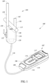
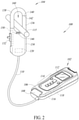
- FIGS 1 and 2 show pictorial diagrams of an electrical parameter measurement device 100, according to one non-limiting illustrated implementation.
- the electrical parameter measurement device 100 includes a main body or housing 102 and an electrical parameter sensor probe 104.
- the sensor probe 104 comprises a body 134 coupled to an interface connector 108 via a cable 110.
- the main body 102 includes an interface connector 106 that detachably couples with the corresponding interface connector 108 of the sensor probe 104.
- the main body 102 further includes a display 112 that presents measurement results and other information, and an input user interface 114 for inputting information such as measurement instructions or other information.
- the display 112 may be a display of any suitable type, such as a liquid crystal display (LCD), a light-emitting diode (LED) display, an organic LED display, a plasma display, or an e-ink display.
- the main body 102 may include one or more audio or haptic outputs (not shown), such as one or more speakers, buzzers, vibration devices, etc.
- the input user interface 114 comprises a plurality of buttons, but in other implementations the user interface may additionally or alternatively include one or more other types of input devices, such as a touch pad, touch screen, wheel, knob, dial, microphone, etc.
- the main body 102 may also include a power supply, such as a battery or battery pack, for supplying power to the various components of the main body and the sensor probe 104.
- the main body 102 also includes control circuitry 116 that controls the various operations of the electrical parameter measurement device 100, such as receiving signals from the sensor probe 104, determining one or more electrical parameters of an insulated conductor 115 under measurement, and outputting measurement data (e.g., to the display 112).
- the control circuitry 116 may include one or more processors (e.g., microcontroller, DSP, ASIC, FPGA), one or more types of memory (e.g., ROM, RAM, flash memory, other non-transitory storage media), and/or one or more other types of processing or control related components.
- the main body 102 may include a wireless communications subsystem 118, which may include one or more of a Bluetooth ® module, a Wi-Fi ® module, a ZIGBEE ® module, a near field communication (NFC) module, etc.
- the main body 102 may be operative to communicate wirelessly via the wireless communications subsystem 118 with an external receiving system, such as a computer, smart phone, tablet, personal digital assistant, etc., so as to transmit measurement results to the external system or to receive instruction signals or input information from an external system.
- the main body 102 may additionally or alternatively include a wired communications subsystem, such as a USB interface, etc.
- a plurality of different sensor probes may be detachably coupleable to the main body 102 of the electrical parameter measurement device 100.
- the plurality of sensor probes may differ in at least one of shape, structure, or function, for example, to provide various functionality for the electrical parameter measurement device 100.
- the sensor probe 104 includes a flexible arm 138 coupled to the body 134.
- the flexible arm 138 is movable between a closed position (shown in Figure 2 ) and an open position (shown in Figure 1 ). In the closed position shown in Figure 2 , an end portion 140 of the flexible arm 138 abuts an end portion 142 of a fixed arm or portion 136 of the body 134 to form an enclosed measurement loop that defines a measurement area 160 ( Figure 2 ) that receives the insulated conductor 115.
- the flexible arm 138 opens at least a portion of the measurement loop by separating the end 140 of the flexible arm 138 from the end 142 of the fixed arm 136 to allow the insulated conductor 115 to move into and out of the measurement area 160.
- the sensor probe 104 also includes an actuator 150 operatively coupled to the flexible arm 138.
- the actuator 150 may include a slide switch 132 or other mechanism that is movable by a user. In operation, responsive to actuation by the user, the actuator 150 moves the flexible arm 138 from the closed position to the open position.
- the actuator 150 biases the flexible arm 138 in the closed position shown in Figure 2 .
- the actuator 150 may include a biasing element (e.g., a spring) that biases the flexible arm 138 in the closed position and biases the slide switch 132 in the upward position shown in Figure 2 .
- the user may move the flexible arm 138 from the closed position into the open position by moving the slide switch 132 downward (as shown). While the user is maintaining the slide switch 132 in the downward position against the biasing force, the user may insert the insulated conductor 115 into the measurement area 160.
- the user may then release the slide switch 132, such that the biasing force of the actuator 150 causes the flexible arm 138 to return to the closed position, thereby securing the insulated conductor 115 within the measurement area 160 so that a measurement may be obtained.
- the user may again move the flexible arm 138 into the open position to release the conductor 115 from the measurement area 160 of the sensor probe 104.
- the flexible arm 138 is formed from a unitary structure that is deformable between the closed position and the opened position.
- the flexible arm 138 may be formed from an elastomer or other material that elastically deforms between the closed position wherein the ends 140 and 142 abut each other and the open position wherein the ends 140 and 142 are spaced apart by a distance sufficient for the insulated conductor 115 to be moved into the measurement area 160.
- the flexible arm 138 may include a plurality of portions (e.g., "links") that are movable with respect to each other.
- the actuator 150 may be operative to selectively move the plurality of portions relative to each other to move the flexible arm 138 between the closed position and the open position.
- the body 134 of sensor probe 104 includes one or more non-contact sensors 146 (e.g., a non-contact voltage sensor) coupled thereto that are operative to sense one or more electrical parameters in an insulated conductor 115 under test. Additionally or alternatively, one or more non-contact sensors 146 may be coupled to the flexible arm 138. The non-contact sensor 146 may be electrically connected to the signal cable 110 such that signals from the sensor are sent to the main body 102 for processing.
- non-contact sensors 146 e.g., a non-contact voltage sensor
- the non-contact sensors may include a non-contact voltage sensor, a Hall Effect element, a current transformer, a fluxgate sensor, a Rogowski coil, an anisotropic magnetoresistance (AMR) sensor, a giant magnetoresistance (GMR) sensor, other types of sensors operative to sense an electrical parameter of the conductor 115 without requiring galvanic contact, or any combination thereof.
- Various non-limiting examples of non-contact sensors are disclosed in U.S. Provisional Patent Application No. 62/421,124, filed November 11, 2016 ; U.S. Patent Application No. 15/345,256, filed November 7, 2016 ; U.S. Patent Application No. 15/413,025, filed January 23, 2017 ; U.S. Patent Application No. 15/412,891, filed January 23, 2017 ; U.S. Patent Application No. 15/604,320, filed May 24, 2017 , and U.S. Patent Application Serial No. 15/625,745, filed June 16, 2017 .
- the sensor probe 104 may also include processing or control circuitry 120 operatively coupled to the one or more sensors 146 that is operative to process sensor signals received from the one or more sensors 146, and is operative to send sensor data indicative of such sensor signals to the control circuitry 116 of the main body 102 for processing.
- the control circuitry 120 may additionally or alternatively include conditioning or conversion circuitry that is operative to condition or convert the signals into a form receivable by the main body 102, such as an analog form (e.g., 0-1 V) or a digital form (e.g., 8 bits, 16 bits, 64 bits).
- the control circuitry 120 of the sensor probe 104 transmits measurement data from the sensor(s) 146 to the main body 102 of the electrical parameter measurement device 100, and the control circuitry 116 determines one or more electrical parameters in the conductor 115 based on the received measurement data.
- the control circuitry 116 may utilize one or more mathematical formulas, lookup tables, calibration factors, etc., to determine the one or more electrical parameters.
- some electrical parameters, such as power or phase angles may be derived from other determined electrical parameters, such as current and voltage.
- the interface connector 108 may be detachably coupled with the corresponding interface connector 106 on the main body 102 of the electrical parameter measurement device 100, for example, such that different sensor probes may be coupled to the main body 102.
- the interface connector 108 of the sensor probe 104 may be configured as one of a plug and a socket, and the interface connector 106 of the main body 102 may be configured as the other of a plug and sockct.
- the interface connectors 106 and 108 may be configured as different types of connectors that are operative to be detachably coupled to each other.
- the sensor probe 104 may be fixedly connected to the main body 102 by the cable 110.
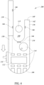
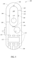
- Figures 3-5 show another implementation of an electrical parameter measurement device 200 in accordance with the present disclosure.
- the electrical parameter measurement device 200 may be similar or identical to the electrical parameter measurement device 100 discussed above in many respects. Thus, the discussion above may apply to the electrical parameter measurement device 200. Further, components of the electrical parameter measurement device 200 that are similar or identical to corresponding components of the electrical parameter measurement device 100 are designated with the same reference numerals, and a discussion of such components is not repeated herein for the sake of brevity.
- the sensor probe portion and the main body portion are contained in a single housing 134.
- Figure 3 shows the electrical parameter measurement device 200 when the flexible arm 138 is in the closed position prior to inserting the insulated conductor 115 into the measurement area 160.
- Figure 4 shows the electrical parameter measurement device 200 when the user has pressed down (as shown) on the slide switch 132 to cause the actuator 150 to move the flexible arm 138 into the open position, wherein the conductor 115 can be positioned in the measurement area 160.
- Figure 5 shows the electrical parameter measurement device 200 when the user has released the slide switch 132, or moved the slide switch upward in cases where the slide switch is not biased upward, which causes the actuator 150 to cause the flexible arm 138 to return to the closed position, thereby securing the conductor 115 in the measurement area.
- the electrical parameter measurement device 200 may utilize non-contact sensors 146 to measure one or more electrical parameters (e.g., voltage, current, power, phase angle) of the insulated conductor 115.
- the electrical parameter measurement device 200 includes four non-contact sensors 146.
- the electrical parameter measurement device 200 includes two non-contact sensors 146 positioned on the flexible arm 138, one non-contact sensor on the fixed arm 136 of the body 134, and one non-contact sensor on a portion of the body proximate to the bottom of the measurement area 160.
- the electrical parameter measurement device 200 may utilize one, some, or all of the non-contact sensors 146 to determine one or more electrical parameters of the insulated conductor.
- non-contact sensors 146 are shown, in other implementations fewer or more non-contact sensors may be used to provide the desired functionality. Additionally, the non-contact sensors 146 may be positioned differently, so long as they are able to detect or measure electrical parameters in the insulated conductor 115 when the conductor is positioned in the measurement area 160.
- the non-contact sensors may include one or more of a non-contact voltage sensor, a Hall Effect element, a current transformer, a fluxgate sensor, a Rogowski coil, an anisotropic magnetoresistance (AMR) sensor, a giant magnetoresistance (GMR) sensor, other types of sensors operative to sense an electrical parameter of the conductor 115 without requiring galvanic contact, or any combinations thereof.
- a non-contact voltage sensor a Hall Effect element
- a current transformer e.g., a current transformer
- a fluxgate sensor e.gowski coil
- AMR anisotropic magnetoresistance
- GMR giant magnetoresistance
- signal bearing media include, but are not limited to, the following: recordable type media such as floppy disks, hard disk drives, CD ROMs, digital tape, and computer memory.
- Examples provide an electrical parameter sensor probe operative to detect an electrical parameter in an insulated conductor without requiring galvanic contact with the insulated conductor, the electrical parameter sensor probe comprising: a body; a flexible arm coupled to the body, the flexible arm movable between a closed position and an open position, wherein, in the closed position, the flexible arm and a portion of the body form an enclosed measurement loop that defines a measurement area that receives the insulated conductor and, in the open position, the flexible arm opens at least a portion of the measurement loop to allow the insulated conductor to move into and out of the measurement area; an actuator operatively coupled to the flexible arm, in operation, responsive to actuation by a user the actuator moves the flexible arm from the closed position to the open position; and at least one non-contact sensor coupled to at least one of the body and the flexible arm, the at least one non-contact sensor positioned proximate the measurement area and operative to sense at least one electrical parameter in the insulated conductor when the insulated conductor is positioned within the measurement area.
- Some examples further comprise the electrical parameter sensor probe, wherein the actuator biases the flexible arm in the closed position.
- Some examples further comprise the electrical parameter sensor probe, wherein the flexible arm comprises a unitary structure that is deformable between the closed position and the opened position.
- Some examples further comprise the electrical parameter sensor probe, wherein the flexible arm comprises a plurality of portions that are movable with respect to each other, and the actuator is operative to move the portions relative to each other to move the flexible arm between the closed position and the open position.
- Some examples further comprise the electrical parameter sensor probe, wherein the plurality of portions comprise links that are movable with respect to each other.
- Some examples further comprise the electrical parameter sensor probe, wherein the flexible arm has a curved shape when the flexible arm is in the closed position, and the actuator causes the flexible arm to straighten from the curved shape to be in the open position.
- Some examples further comprise the electrical parameter sensor probe, wherein the at least one non-contact sensor comprises at least one of a non-contact voltage sensor or a non-contact current sensor.
- Some further examples comprise the electrical parameter sensor probe, wherein the at least one non-contact sensor is coupled to the flexible arm.
- Some further examples comprise, the electrical parameter sensor probe, wherein the at least one non-contact sensor comprises at least one non-contact sensor coupled to the flexible arm and at least one non-contact sensor coupled to the body of the electrical parameter sensor probe.
- Some further examples comprise the electrical parameter sensor probe, further comprising an interface connector operatively coupled to the at least one non-contact sensor, the interface connector being detachably coupleable to a corresponding interface connector of a main body of a non-contact electrical parameter measurement device.
- Some further examples comprise the electrical parameter sensor probe, wherein the at least one non-contact sensor comprises at least one of a non-contact voltage sensor, a Hall Effect sensor, a fluxgate sensor, a Rogowski coil, an anisotropic magnetoresistance (AMR) sensor, or a giant magnetoresistance (GMR) sensor.
- the at least one non-contact sensor comprises at least one of a non-contact voltage sensor, a Hall Effect sensor, a fluxgate sensor, a Rogowski coil, an anisotropic magnetoresistance (AMR) sensor, or a giant magnetoresistance (GMR) sensor.
- Examples provide a device for measuring an electrical parameter in an insulated conductor, the device comprising: an electrical parameter sensor probe, comprising: a body; a flexible arm coupled to the body, the flexible arm movable between a closed position and an open position, wherein, in the closed position, the flexible arm and a portion of the body form an enclosed measurement loop that defines a measurement area that receives the insulated conductor and, in the open position, the flexible arm opens at least a portion of the measurement loop to allow the insulated conductor to move into and out of the measurement area; an actuator operatively coupled to the flexible arm, in operation, responsive to actuation by a user the actuator moves the flexible arm from the closed position to the open position; and at least one non-contact sensor coupled to at least one of the body and the flexible arm, the at least one non-contact sensor positioned proximate the measurement area and operative to sense at least one electrical parameter in the insulated conductor when the insulated conductor is positioned within the measurement area; and control circuitry communicatively coupleable to the at least
- Some further examples comprise a main body that contains the control circuitry.
- Some further examples comprise a main body comprising at least one interface connector, and the electrical parameter sensor probe is detachably connectable to the at least one interface connector of the main body.
- Some examples may further comprise a main body that includes the electrical parameter sensor probe and the control circuitry.
- control circuitry in operation, processes the received sensor data to determine a voltage in the insulated conductor.
- control circuitry in operation, processes the received sensor data to determine a voltage and a current in the insulated conductor.
- Some further examples comprise a wireless communications subsystem operatively coupled to the control circuitry, in operation, the wireless communication subsystem wirelessly transmits the determined electrical parameter to an external system.
- Some further examples comprise a display that, in operation, visually presents the determined electrical parameter to a user of the device.
- Some further examples comprise the at least one non-contact sensor comprising at least one of a non-contact voltage sensor, a Hall Effect sensor, a fluxgate sensor, a Rogowski coil, an anisotropic magnetoresistance (AMR) sensor, or a giant magnetoresistance (GMR) sensor.
- a non-contact voltage sensor comprising at least one of a non-contact voltage sensor, a Hall Effect sensor, a fluxgate sensor, a Rogowski coil, an anisotropic magnetoresistance (AMR) sensor, or a giant magnetoresistance (GMR) sensor.
- AMR anisotropic magnetoresistance
- GMR giant magnetoresistance
- Examples provide a device for measuring an electrical parameter in an insulated conductor, the device comprising: a body; a flexible arm coupled to the body, the flexible arm movable between a closed position and an open position, wherein, in the closed position, the flexible arm and a portion of the body form an enclosed measurement loop that defines a measurement area that receives the insulated conductor and, in the open position, the flexible arm opens at least a portion of the measurement loop to allow the insulated conductor to move into and out of the measurement area; an actuator operatively coupled to the flexible arm, in operation, responsive to actuation by a user the actuator moves the flexible arm from the closed position to the open position; at least one non-contact sensor coupled to at least one of the body and the flexible arm, the at least one non-contact sensor positioned proximate the measurement area and operative to sense at least one electrical parameter in the insulated conductor when the insulated conductor is positioned within the measurement area; and control circuitry communicatively coupleable to the at least one non-contact sensor, in operation, the
Landscapes
- Physics & Mathematics (AREA)
- General Physics & Mathematics (AREA)
- Engineering & Computer Science (AREA)
- Power Engineering (AREA)
- Computer Networks & Wireless Communication (AREA)
- Measuring Instrument Details And Bridges, And Automatic Balancing Devices (AREA)
- Measuring Leads Or Probes (AREA)
Applications Claiming Priority (1)
| Application Number | Priority Date | Filing Date | Title |
|---|---|---|---|
| US15/977,148 US10908188B2 (en) | 2018-05-11 | 2018-05-11 | Flexible jaw probe for non-contact electrical parameter measurement |
Publications (2)
| Publication Number | Publication Date |
|---|---|
| EP3567381A1 EP3567381A1 (en) | 2019-11-13 |
| EP3567381B1 true EP3567381B1 (en) | 2022-02-23 |
Family
ID=66476568
Family Applications (1)
| Application Number | Title | Priority Date | Filing Date |
|---|---|---|---|
| EP19173650.3A Active EP3567381B1 (en) | 2018-05-11 | 2019-05-09 | Flexible jaw probe for non-contact electrical parameter measurement |
Country Status (5)
| Country | Link |
|---|---|
| US (1) | US10908188B2 (enExample) |
| EP (1) | EP3567381B1 (enExample) |
| JP (1) | JP7219669B2 (enExample) |
| CN (1) | CN110470924B (enExample) |
| TW (1) | TWI791110B (enExample) |
Families Citing this family (7)
| Publication number | Priority date | Publication date | Assignee | Title |
|---|---|---|---|---|
| CN105432064B (zh) * | 2013-03-15 | 2019-05-10 | 弗兰克公司 | 使用单独无线移动设备的红外图像的可见视听注释 |
| GB2595209A (en) * | 2020-05-11 | 2021-11-24 | Trend Networks Ltd | A detachable test instrument remote controller |
| CN114019226A (zh) * | 2021-10-27 | 2022-02-08 | 北京大学 | 一种无接触式电量测量与记录装置 |
| US20250341562A1 (en) * | 2023-01-25 | 2025-11-06 | Power Probe Group, Inc. | Diagnostic probe apparatus and related systems and methods |
| LU503820B1 (de) * | 2023-03-31 | 2024-09-30 | Phoenix Contact Gmbh & Co | Messgerät zur kontaktlosen Strommessung und Verfahren zu dessen Kalibrierung |
| US12487259B2 (en) * | 2023-07-28 | 2025-12-02 | Senva Inc. | Contactless power meter |
| WO2025222068A1 (en) * | 2024-04-19 | 2025-10-23 | The Research Foundation For The State University Of New York | Tunneling magnetoresistance sensor system and method for high power density power electronics systems |
Family Cites Families (68)
| Publication number | Priority date | Publication date | Assignee | Title |
|---|---|---|---|---|
| FR1478330A (fr) | 1965-04-23 | 1967-04-28 | Telemecanique Electrique | Perfectionnement à la mesure des courants industriels jusqu' à des fréquences élevées |
| US5473244A (en) | 1992-09-17 | 1995-12-05 | Libove; Joel M. | Apparatus for measuring voltages and currents using non-contacting sensors |
| JPH06222087A (ja) | 1993-01-27 | 1994-08-12 | Hamamatsu Photonics Kk | 電圧検出装置 |
| US5973501A (en) | 1993-10-18 | 1999-10-26 | Metropolitan Industries, Inc. | Current and voltage probe for measuring harmonic distortion |
| JPH09184866A (ja) | 1995-12-28 | 1997-07-15 | Sumitomo Electric Ind Ltd | ケーブルの活線下劣化診断方法 |
| US6043640A (en) | 1997-10-29 | 2000-03-28 | Fluke Corporation | Multimeter with current sensor |
| US6118270A (en) | 1998-02-17 | 2000-09-12 | Singer; Jerome R. | Apparatus for fast measurements of current and power with scaleable wand-like sensor |
| IL127699A0 (en) | 1998-12-23 | 1999-10-28 | Bar Dov Aharon | Method and device for non contact detection of external electric or magnetic fields |
| DE19962323A1 (de) | 1999-12-23 | 2001-07-19 | Metrawatt Gmbh Gossen | Elektrische Meßvorrichtung |
| JP2002048834A (ja) * | 2000-08-03 | 2002-02-15 | Kanto Denki Hoan Kyokai | 探査器クランプ補助操作棒 |
| US6456060B1 (en) * | 2000-08-29 | 2002-09-24 | Actuant Corporation | Multi-meter with locking clamp |
| US6812685B2 (en) | 2001-03-22 | 2004-11-02 | Actuant Corporation | Auto-selecting, auto-ranging contact/noncontact voltage and continuity tester |
| JP3761470B2 (ja) | 2001-04-04 | 2006-03-29 | 北斗電子工業株式会社 | 非接触電圧計測方法及び装置並びに検出プローブ |
| US6644636B1 (en) | 2001-10-26 | 2003-11-11 | M. Terry Ryan | Clamp adapter |
| JP2003139801A (ja) | 2001-11-05 | 2003-05-14 | Hioki Ee Corp | 計器用変流器 |
| CN2639905Y (zh) | 2003-07-25 | 2004-09-08 | 深圳市纳米电子有限公司 | 一种钳形表校验仪 |
| BRPI0506472A (pt) | 2004-01-07 | 2007-02-06 | Suparules Ltd | dispositivo para medição de voltagem |
| US7256588B2 (en) | 2004-04-16 | 2007-08-14 | General Electric Company | Capacitive sensor and method for non-contacting gap and dielectric medium measurement |
| DE102004063249A1 (de) | 2004-12-23 | 2006-07-13 | Fraunhofer-Gesellschaft zur Förderung der angewandten Forschung e.V. | Sensorsystem und Verfahren zur kapazitiven Messung elektromagnetischer Signale biologischen Ursprungs |
| JP4611774B2 (ja) | 2005-03-04 | 2011-01-12 | 東日本電信電話株式会社 | 非接触型電圧検出方法及び非接触型電圧検出装置 |
| US7466145B2 (en) | 2005-10-12 | 2008-12-16 | Hioki Denki Kabushiki Kaisha | Voltage measuring apparatus and power measuring apparatus |
| JP4607753B2 (ja) | 2005-12-16 | 2011-01-05 | 日置電機株式会社 | 電圧測定装置および電力測定装置 |
| JP4607752B2 (ja) | 2005-12-16 | 2011-01-05 | 日置電機株式会社 | 可変容量回路、電圧測定装置および電力測定装置 |
| JP4713358B2 (ja) | 2006-02-08 | 2011-06-29 | 日置電機株式会社 | 電圧検出装置 |
| JP4648228B2 (ja) | 2006-03-24 | 2011-03-09 | 日置電機株式会社 | 電圧検出装置および初期化方法 |
| JP5106798B2 (ja) | 2006-06-22 | 2012-12-26 | 日置電機株式会社 | 電圧測定装置 |
| JP4726722B2 (ja) | 2006-07-03 | 2011-07-20 | 日置電機株式会社 | 電圧測定装置 |
| JP4726721B2 (ja) | 2006-07-03 | 2011-07-20 | 日置電機株式会社 | 電圧測定装置 |
| JP4629625B2 (ja) | 2006-07-12 | 2011-02-09 | 日置電機株式会社 | 電圧測定装置 |
| GB0614261D0 (en) | 2006-07-18 | 2006-08-30 | Univ Sussex The | Electric Potential Sensor |
| JP5106909B2 (ja) | 2007-04-10 | 2012-12-26 | 日置電機株式会社 | 線間電圧測定装置 |
| JP4927632B2 (ja) | 2007-04-13 | 2012-05-09 | 日置電機株式会社 | 電圧測定装置 |
| JP5144110B2 (ja) | 2007-04-13 | 2013-02-13 | 日置電機株式会社 | 電圧測定装置 |
| US7944197B2 (en) * | 2007-05-18 | 2011-05-17 | Rishabh Instruments Private Limited | Clamp meter with rotary mechanism for clamp jaws |
| JP5069978B2 (ja) | 2007-08-31 | 2012-11-07 | 株式会社ダイヘン | 電流・電圧検出用プリント基板および電流・電圧検出器 |
| JP5160248B2 (ja) | 2008-01-18 | 2013-03-13 | 日置電機株式会社 | 電圧検出装置 |
| US20100090682A1 (en) | 2008-02-14 | 2010-04-15 | Armstrong Eric A | Multi-Meter Test Lead Probe For Hands-Free Electrical Measurement of Control Panel Industrial Terminal Blocks |
| US8222886B2 (en) | 2008-06-18 | 2012-07-17 | Hioki Denki Kabushiki Kaisha | Voltage detecting apparatus and line voltage detecting apparatus having a detection electrode disposed facing a detected object |
| JP5389389B2 (ja) | 2008-07-22 | 2014-01-15 | 日置電機株式会社 | 線間電圧測定装置およびプログラム |
| CN101881791B (zh) | 2009-04-30 | 2015-08-05 | 日置电机株式会社 | 电压检测装置 |
| JP5340817B2 (ja) | 2009-06-11 | 2013-11-13 | 日置電機株式会社 | 電圧検出装置 |
| US8856555B2 (en) | 2009-07-17 | 2014-10-07 | Fluke Corporation | Power state coordination for portable test tools |
| JP5420387B2 (ja) | 2009-12-09 | 2014-02-19 | 日置電機株式会社 | 電圧検出装置 |
| JP5474707B2 (ja) | 2010-08-30 | 2014-04-16 | 日置電機株式会社 | 電圧検出装置用の検出回路および電圧検出装置 |
| US8680845B2 (en) | 2011-02-09 | 2014-03-25 | International Business Machines Corporation | Non-contact current and voltage sensor |
| US9063184B2 (en) | 2011-02-09 | 2015-06-23 | International Business Machines Corporation | Non-contact current-sensing and voltage-sensing clamp |
| JP5834663B2 (ja) | 2011-04-06 | 2015-12-24 | 富士通株式会社 | 交流電力測定装置 |
| JP5834292B2 (ja) | 2011-05-09 | 2015-12-16 | アルプス・グリーンデバイス株式会社 | 電流センサ |
| BR112014002634B1 (pt) | 2011-08-03 | 2021-06-15 | Fluke Corporation | Método de obtenção e manutenção de registro de manutenção,sistema para obtenção e manutenção de registros de manutenção e meio de armazenamento legível por computador. |
| US8754636B2 (en) | 2011-12-07 | 2014-06-17 | Brymen Technology Corporation | Clamp meter with multipoint measurement |
| CN204214925U (zh) | 2012-03-16 | 2015-03-18 | 菲力尔系统公司 | 电传感器和电传感器标签 |
| US20140035607A1 (en) | 2012-08-03 | 2014-02-06 | Fluke Corporation | Handheld Devices, Systems, and Methods for Measuring Parameters |
| JP5981271B2 (ja) | 2012-08-28 | 2016-08-31 | 日置電機株式会社 | 電圧測定用センサおよび電圧測定装置 |
| US9007077B2 (en) | 2012-08-28 | 2015-04-14 | International Business Machines Corporation | Flexible current and voltage sensor |
| JP5981270B2 (ja) | 2012-08-28 | 2016-08-31 | 日置電機株式会社 | 電圧測定用センサおよび電圧測定装置 |
| US9625535B2 (en) | 2013-08-07 | 2017-04-18 | Allegro Microsystems, Llc | Systems and methods for computing a position of a magnetic target |
| JP2015114245A (ja) | 2013-12-12 | 2015-06-22 | 日置電機株式会社 | クランプセンサおよび測定装置 |
| CN106133532B (zh) * | 2014-03-20 | 2019-07-30 | 公立大学法人大阪市立大学 | 钳形电流表 |
| JP6210938B2 (ja) | 2014-06-18 | 2017-10-11 | 日置電機株式会社 | 非接触型電圧検出装置 |
| US9689903B2 (en) | 2014-08-12 | 2017-06-27 | Analog Devices, Inc. | Apparatus and methods for measuring current |
| US10602082B2 (en) | 2014-09-17 | 2020-03-24 | Fluke Corporation | Triggered operation and/or recording of test and measurement or imaging tools |
| TWI649568B (zh) | 2014-10-17 | 2019-02-01 | 日商日置電機股份有限公司 | Voltage detecting device |
| US10271020B2 (en) | 2014-10-24 | 2019-04-23 | Fluke Corporation | Imaging system employing fixed, modular mobile, and portable infrared cameras with ability to receive, communicate, and display data and images with proximity detection |
| US9541581B2 (en) | 2014-10-27 | 2017-01-10 | Fluke Corporation | Flexible current sensor |
| US10168356B2 (en) * | 2015-08-19 | 2019-01-01 | Tektronix, Inc. | Test and measurement probe with adjustable test point contact |
| JP2017146143A (ja) | 2016-02-16 | 2017-08-24 | 中国電力株式会社 | 間接活線工具用電流計 |
| ES1160858Y (es) | 2016-06-20 | 2016-10-04 | Smilics Tech S L | Sensor de corriente de tipo flexible |
| US10502807B2 (en) | 2017-09-05 | 2019-12-10 | Fluke Corporation | Calibration system for voltage measurement devices |
-
2018
- 2018-05-11 US US15/977,148 patent/US10908188B2/en active Active
-
2019
- 2019-05-06 TW TW108115560A patent/TWI791110B/zh active
- 2019-05-09 EP EP19173650.3A patent/EP3567381B1/en active Active
- 2019-05-10 CN CN201910389033.2A patent/CN110470924B/zh active Active
- 2019-05-13 JP JP2019090861A patent/JP7219669B2/ja active Active
Also Published As
| Publication number | Publication date |
|---|---|
| CN110470924A (zh) | 2019-11-19 |
| TW201947228A (zh) | 2019-12-16 |
| JP2020008567A (ja) | 2020-01-16 |
| EP3567381A1 (en) | 2019-11-13 |
| US10908188B2 (en) | 2021-02-02 |
| TWI791110B (zh) | 2023-02-01 |
| CN110470924B (zh) | 2022-04-08 |
| JP7219669B2 (ja) | 2023-02-08 |
| US20190346487A1 (en) | 2019-11-14 |
Similar Documents
| Publication | Publication Date | Title |
|---|---|---|
| EP3567382B1 (en) | Clamp probe for non-contact electrical parameter measurement | |
| EP3567381B1 (en) | Flexible jaw probe for non-contact electrical parameter measurement | |
| EP3567385B1 (en) | Adjustable length rogowski coil measurement device with non-contact voltage measurement | |
| US11112433B2 (en) | Non-contact electrical parameter measurement device with clamp jaw assembly | |
| US10352967B2 (en) | Non-contact electrical parameter measurement systems | |
| EP3318883B1 (en) | Non-contact voltage measurement system | |
| EP3862762B1 (en) | Non-contact voltage measurement with adjustable size rogowski coil | |
| US11513140B2 (en) | Sensor probe with clamp having adjustable interior region for non-contact electrical measurement |
Legal Events
| Date | Code | Title | Description |
|---|---|---|---|
| PUAI | Public reference made under article 153(3) epc to a published international application that has entered the european phase |
Free format text: ORIGINAL CODE: 0009012 |
|
| STAA | Information on the status of an ep patent application or granted ep patent |
Free format text: STATUS: THE APPLICATION HAS BEEN PUBLISHED |
|
| AK | Designated contracting states |
Kind code of ref document: A1 Designated state(s): AL AT BE BG CH CY CZ DE DK EE ES FI FR GB GR HR HU IE IS IT LI LT LU LV MC MK MT NL NO PL PT RO RS SE SI SK SM TR |
|
| AX | Request for extension of the european patent |
Extension state: BA ME |
|
| STAA | Information on the status of an ep patent application or granted ep patent |
Free format text: STATUS: REQUEST FOR EXAMINATION WAS MADE |
|
| 17P | Request for examination filed |
Effective date: 20200513 |
|
| RBV | Designated contracting states (corrected) |
Designated state(s): AL AT BE BG CH CY CZ DE DK EE ES FI FR GB GR HR HU IE IS IT LI LT LU LV MC MK MT NL NO PL PT RO RS SE SI SK SM TR |
|
| GRAP | Despatch of communication of intention to grant a patent |
Free format text: ORIGINAL CODE: EPIDOSNIGR1 |
|
| STAA | Information on the status of an ep patent application or granted ep patent |
Free format text: STATUS: GRANT OF PATENT IS INTENDED |
|
| INTG | Intention to grant announced |
Effective date: 20210913 |
|
| GRAS | Grant fee paid |
Free format text: ORIGINAL CODE: EPIDOSNIGR3 |
|
| GRAA | (expected) grant |
Free format text: ORIGINAL CODE: 0009210 |
|
| STAA | Information on the status of an ep patent application or granted ep patent |
Free format text: STATUS: THE PATENT HAS BEEN GRANTED |
|
| AK | Designated contracting states |
Kind code of ref document: B1 Designated state(s): AL AT BE BG CH CY CZ DE DK EE ES FI FR GB GR HR HU IE IS IT LI LT LU LV MC MK MT NL NO PL PT RO RS SE SI SK SM TR |
|
| REG | Reference to a national code |
Ref country code: GB Ref legal event code: FG4D |
|
| REG | Reference to a national code |
Ref country code: CH Ref legal event code: EP |
|
| REG | Reference to a national code |
Ref country code: AT Ref legal event code: REF Ref document number: 1470868 Country of ref document: AT Kind code of ref document: T Effective date: 20220315 |
|
| REG | Reference to a national code |
Ref country code: IE Ref legal event code: FG4D |
|
| REG | Reference to a national code |
Ref country code: DE Ref legal event code: R096 Ref document number: 602019011776 Country of ref document: DE |
|
| REG | Reference to a national code |
Ref country code: LT Ref legal event code: MG9D |
|
| REG | Reference to a national code |
Ref country code: NL Ref legal event code: MP Effective date: 20220223 |
|
| REG | Reference to a national code |
Ref country code: AT Ref legal event code: MK05 Ref document number: 1470868 Country of ref document: AT Kind code of ref document: T Effective date: 20220223 |
|
| PG25 | Lapsed in a contracting state [announced via postgrant information from national office to epo] |
Ref country code: SE Free format text: LAPSE BECAUSE OF FAILURE TO SUBMIT A TRANSLATION OF THE DESCRIPTION OR TO PAY THE FEE WITHIN THE PRESCRIBED TIME-LIMIT Effective date: 20220223 Ref country code: RS Free format text: LAPSE BECAUSE OF FAILURE TO SUBMIT A TRANSLATION OF THE DESCRIPTION OR TO PAY THE FEE WITHIN THE PRESCRIBED TIME-LIMIT Effective date: 20220223 Ref country code: PT Free format text: LAPSE BECAUSE OF FAILURE TO SUBMIT A TRANSLATION OF THE DESCRIPTION OR TO PAY THE FEE WITHIN THE PRESCRIBED TIME-LIMIT Effective date: 20220623 Ref country code: NO Free format text: LAPSE BECAUSE OF FAILURE TO SUBMIT A TRANSLATION OF THE DESCRIPTION OR TO PAY THE FEE WITHIN THE PRESCRIBED TIME-LIMIT Effective date: 20220523 Ref country code: NL Free format text: LAPSE BECAUSE OF FAILURE TO SUBMIT A TRANSLATION OF THE DESCRIPTION OR TO PAY THE FEE WITHIN THE PRESCRIBED TIME-LIMIT Effective date: 20220223 Ref country code: LT Free format text: LAPSE BECAUSE OF FAILURE TO SUBMIT A TRANSLATION OF THE DESCRIPTION OR TO PAY THE FEE WITHIN THE PRESCRIBED TIME-LIMIT Effective date: 20220223 Ref country code: HR Free format text: LAPSE BECAUSE OF FAILURE TO SUBMIT A TRANSLATION OF THE DESCRIPTION OR TO PAY THE FEE WITHIN THE PRESCRIBED TIME-LIMIT Effective date: 20220223 Ref country code: ES Free format text: LAPSE BECAUSE OF FAILURE TO SUBMIT A TRANSLATION OF THE DESCRIPTION OR TO PAY THE FEE WITHIN THE PRESCRIBED TIME-LIMIT Effective date: 20220223 Ref country code: BG Free format text: LAPSE BECAUSE OF FAILURE TO SUBMIT A TRANSLATION OF THE DESCRIPTION OR TO PAY THE FEE WITHIN THE PRESCRIBED TIME-LIMIT Effective date: 20220523 |
|
| PG25 | Lapsed in a contracting state [announced via postgrant information from national office to epo] |
Ref country code: PL Free format text: LAPSE BECAUSE OF FAILURE TO SUBMIT A TRANSLATION OF THE DESCRIPTION OR TO PAY THE FEE WITHIN THE PRESCRIBED TIME-LIMIT Effective date: 20220223 Ref country code: LV Free format text: LAPSE BECAUSE OF FAILURE TO SUBMIT A TRANSLATION OF THE DESCRIPTION OR TO PAY THE FEE WITHIN THE PRESCRIBED TIME-LIMIT Effective date: 20220223 Ref country code: GR Free format text: LAPSE BECAUSE OF FAILURE TO SUBMIT A TRANSLATION OF THE DESCRIPTION OR TO PAY THE FEE WITHIN THE PRESCRIBED TIME-LIMIT Effective date: 20220524 Ref country code: FI Free format text: LAPSE BECAUSE OF FAILURE TO SUBMIT A TRANSLATION OF THE DESCRIPTION OR TO PAY THE FEE WITHIN THE PRESCRIBED TIME-LIMIT Effective date: 20220223 Ref country code: AT Free format text: LAPSE BECAUSE OF FAILURE TO SUBMIT A TRANSLATION OF THE DESCRIPTION OR TO PAY THE FEE WITHIN THE PRESCRIBED TIME-LIMIT Effective date: 20220223 |
|
| PG25 | Lapsed in a contracting state [announced via postgrant information from national office to epo] |
Ref country code: IS Free format text: LAPSE BECAUSE OF FAILURE TO SUBMIT A TRANSLATION OF THE DESCRIPTION OR TO PAY THE FEE WITHIN THE PRESCRIBED TIME-LIMIT Effective date: 20220623 |
|
| PG25 | Lapsed in a contracting state [announced via postgrant information from national office to epo] |
Ref country code: SM Free format text: LAPSE BECAUSE OF FAILURE TO SUBMIT A TRANSLATION OF THE DESCRIPTION OR TO PAY THE FEE WITHIN THE PRESCRIBED TIME-LIMIT Effective date: 20220223 Ref country code: SK Free format text: LAPSE BECAUSE OF FAILURE TO SUBMIT A TRANSLATION OF THE DESCRIPTION OR TO PAY THE FEE WITHIN THE PRESCRIBED TIME-LIMIT Effective date: 20220223 Ref country code: RO Free format text: LAPSE BECAUSE OF FAILURE TO SUBMIT A TRANSLATION OF THE DESCRIPTION OR TO PAY THE FEE WITHIN THE PRESCRIBED TIME-LIMIT Effective date: 20220223 Ref country code: EE Free format text: LAPSE BECAUSE OF FAILURE TO SUBMIT A TRANSLATION OF THE DESCRIPTION OR TO PAY THE FEE WITHIN THE PRESCRIBED TIME-LIMIT Effective date: 20220223 Ref country code: DK Free format text: LAPSE BECAUSE OF FAILURE TO SUBMIT A TRANSLATION OF THE DESCRIPTION OR TO PAY THE FEE WITHIN THE PRESCRIBED TIME-LIMIT Effective date: 20220223 Ref country code: CZ Free format text: LAPSE BECAUSE OF FAILURE TO SUBMIT A TRANSLATION OF THE DESCRIPTION OR TO PAY THE FEE WITHIN THE PRESCRIBED TIME-LIMIT Effective date: 20220223 |
|
| REG | Reference to a national code |
Ref country code: DE Ref legal event code: R097 Ref document number: 602019011776 Country of ref document: DE |
|
| PG25 | Lapsed in a contracting state [announced via postgrant information from national office to epo] |
Ref country code: AL Free format text: LAPSE BECAUSE OF FAILURE TO SUBMIT A TRANSLATION OF THE DESCRIPTION OR TO PAY THE FEE WITHIN THE PRESCRIBED TIME-LIMIT Effective date: 20220223 |
|
| PLBE | No opposition filed within time limit |
Free format text: ORIGINAL CODE: 0009261 |
|
| REG | Reference to a national code |
Ref country code: CH Ref legal event code: PL |
|
| STAA | Information on the status of an ep patent application or granted ep patent |
Free format text: STATUS: NO OPPOSITION FILED WITHIN TIME LIMIT |
|
| REG | Reference to a national code |
Ref country code: BE Ref legal event code: MM Effective date: 20220531 |
|
| PG25 | Lapsed in a contracting state [announced via postgrant information from national office to epo] |
Ref country code: MC Free format text: LAPSE BECAUSE OF FAILURE TO SUBMIT A TRANSLATION OF THE DESCRIPTION OR TO PAY THE FEE WITHIN THE PRESCRIBED TIME-LIMIT Effective date: 20220223 Ref country code: LU Free format text: LAPSE BECAUSE OF NON-PAYMENT OF DUE FEES Effective date: 20220509 Ref country code: LI Free format text: LAPSE BECAUSE OF NON-PAYMENT OF DUE FEES Effective date: 20220531 Ref country code: CH Free format text: LAPSE BECAUSE OF NON-PAYMENT OF DUE FEES Effective date: 20220531 |
|
| 26N | No opposition filed |
Effective date: 20221124 |
|
| PG25 | Lapsed in a contracting state [announced via postgrant information from national office to epo] |
Ref country code: SI Free format text: LAPSE BECAUSE OF FAILURE TO SUBMIT A TRANSLATION OF THE DESCRIPTION OR TO PAY THE FEE WITHIN THE PRESCRIBED TIME-LIMIT Effective date: 20220223 |
|
| PG25 | Lapsed in a contracting state [announced via postgrant information from national office to epo] |
Ref country code: IE Free format text: LAPSE BECAUSE OF NON-PAYMENT OF DUE FEES Effective date: 20220509 |
|
| PG25 | Lapsed in a contracting state [announced via postgrant information from national office to epo] |
Ref country code: BE Free format text: LAPSE BECAUSE OF NON-PAYMENT OF DUE FEES Effective date: 20220531 |
|
| PG25 | Lapsed in a contracting state [announced via postgrant information from national office to epo] |
Ref country code: IT Free format text: LAPSE BECAUSE OF FAILURE TO SUBMIT A TRANSLATION OF THE DESCRIPTION OR TO PAY THE FEE WITHIN THE PRESCRIBED TIME-LIMIT Effective date: 20220223 |
|
| PG25 | Lapsed in a contracting state [announced via postgrant information from national office to epo] |
Ref country code: HU Free format text: LAPSE BECAUSE OF FAILURE TO SUBMIT A TRANSLATION OF THE DESCRIPTION OR TO PAY THE FEE WITHIN THE PRESCRIBED TIME-LIMIT; INVALID AB INITIO Effective date: 20190509 |
|
| PG25 | Lapsed in a contracting state [announced via postgrant information from national office to epo] |
Ref country code: MK Free format text: LAPSE BECAUSE OF FAILURE TO SUBMIT A TRANSLATION OF THE DESCRIPTION OR TO PAY THE FEE WITHIN THE PRESCRIBED TIME-LIMIT Effective date: 20220223 Ref country code: CY Free format text: LAPSE BECAUSE OF FAILURE TO SUBMIT A TRANSLATION OF THE DESCRIPTION OR TO PAY THE FEE WITHIN THE PRESCRIBED TIME-LIMIT Effective date: 20220223 |
|
| PG25 | Lapsed in a contracting state [announced via postgrant information from national office to epo] |
Ref country code: MT Free format text: LAPSE BECAUSE OF FAILURE TO SUBMIT A TRANSLATION OF THE DESCRIPTION OR TO PAY THE FEE WITHIN THE PRESCRIBED TIME-LIMIT Effective date: 20220223 |
|
| PGFP | Annual fee paid to national office [announced via postgrant information from national office to epo] |
Ref country code: DE Payment date: 20250528 Year of fee payment: 7 |
|
| PGFP | Annual fee paid to national office [announced via postgrant information from national office to epo] |
Ref country code: GB Payment date: 20250520 Year of fee payment: 7 |
|
| PGFP | Annual fee paid to national office [announced via postgrant information from national office to epo] |
Ref country code: FR Payment date: 20250526 Year of fee payment: 7 |