EP3566944B1 - Aircraft landing gear assembly with a ground lock - Google Patents
Aircraft landing gear assembly with a ground lock Download PDFInfo
- Publication number
- EP3566944B1 EP3566944B1 EP19182478.8A EP19182478A EP3566944B1 EP 3566944 B1 EP3566944 B1 EP 3566944B1 EP 19182478 A EP19182478 A EP 19182478A EP 3566944 B1 EP3566944 B1 EP 3566944B1
- Authority
- EP
- European Patent Office
- Prior art keywords
- landing gear
- gear assembly
- engagement surface
- radius
- lock
- Prior art date
- Legal status (The legal status is an assumption and is not a legal conclusion. Google has not performed a legal analysis and makes no representation as to the accuracy of the status listed.)
- Active
Links
- 230000002093 peripheral effect Effects 0.000 claims description 17
- 238000010586 diagram Methods 0.000 description 7
- 230000002829 reductive effect Effects 0.000 description 4
- 230000001133 acceleration Effects 0.000 description 3
- 239000000463 material Substances 0.000 description 3
- 229910000831 Steel Inorganic materials 0.000 description 1
- RTAQQCXQSZGOHL-UHFFFAOYSA-N Titanium Chemical compound [Ti] RTAQQCXQSZGOHL-UHFFFAOYSA-N 0.000 description 1
- 230000002411 adverse Effects 0.000 description 1
- 238000005452 bending Methods 0.000 description 1
- 239000002131 composite material Substances 0.000 description 1
- 230000002401 inhibitory effect Effects 0.000 description 1
- 238000003780 insertion Methods 0.000 description 1
- 230000037431 insertion Effects 0.000 description 1
- 229910052751 metal Inorganic materials 0.000 description 1
- 239000002184 metal Substances 0.000 description 1
- 238000012986 modification Methods 0.000 description 1
- 230000004048 modification Effects 0.000 description 1
- 229920003023 plastic Polymers 0.000 description 1
- 239000004033 plastic Substances 0.000 description 1
- 230000000717 retained effect Effects 0.000 description 1
- 239000010959 steel Substances 0.000 description 1
- 239000010936 titanium Substances 0.000 description 1
- 229910052719 titanium Inorganic materials 0.000 description 1
Images


Classifications
-
- B—PERFORMING OPERATIONS; TRANSPORTING
- B64—AIRCRAFT; AVIATION; COSMONAUTICS
- B64C—AEROPLANES; HELICOPTERS
- B64C25/00—Alighting gear
- B64C25/02—Undercarriages
- B64C25/08—Undercarriages non-fixed, e.g. jettisonable
- B64C25/10—Undercarriages non-fixed, e.g. jettisonable retractable, foldable, or the like
- B64C25/18—Operating mechanisms
- B64C25/26—Control or locking systems therefor
-
- B—PERFORMING OPERATIONS; TRANSPORTING
- B64—AIRCRAFT; AVIATION; COSMONAUTICS
- B64C—AEROPLANES; HELICOPTERS
- B64C25/00—Alighting gear
- B64C25/02—Undercarriages
- B64C25/08—Undercarriages non-fixed, e.g. jettisonable
- B64C25/10—Undercarriages non-fixed, e.g. jettisonable retractable, foldable, or the like
- B64C25/18—Operating mechanisms
- B64C25/20—Operating mechanisms mechanical
-
- E—FIXED CONSTRUCTIONS
- E05—LOCKS; KEYS; WINDOW OR DOOR FITTINGS; SAFES
- E05B—LOCKS; ACCESSORIES THEREFOR; HANDCUFFS
- E05B57/00—Locks in which a pivoted latch is used also as locking means
-
- E—FIXED CONSTRUCTIONS
- E05—LOCKS; KEYS; WINDOW OR DOOR FITTINGS; SAFES
- E05D—HINGES OR SUSPENSION DEVICES FOR DOORS, WINDOWS OR WINGS
- E05D11/00—Additional features or accessories of hinges
- E05D11/10—Devices for preventing movement between relatively-movable hinge parts
-
- E—FIXED CONSTRUCTIONS
- E05—LOCKS; KEYS; WINDOW OR DOOR FITTINGS; SAFES
- E05D—HINGES OR SUSPENSION DEVICES FOR DOORS, WINDOWS OR WINGS
- E05D11/00—Additional features or accessories of hinges
- E05D11/10—Devices for preventing movement between relatively-movable hinge parts
- E05D11/1014—Devices for preventing movement between relatively-movable hinge parts for maintaining the hinge in only one position, e.g. closed
-
- F—MECHANICAL ENGINEERING; LIGHTING; HEATING; WEAPONS; BLASTING
- F16—ENGINEERING ELEMENTS AND UNITS; GENERAL MEASURES FOR PRODUCING AND MAINTAINING EFFECTIVE FUNCTIONING OF MACHINES OR INSTALLATIONS; THERMAL INSULATION IN GENERAL
- F16H—GEARING
- F16H25/00—Gearings comprising primarily only cams, cam-followers and screw-and-nut mechanisms
- F16H25/18—Gearings comprising primarily only cams, cam-followers and screw-and-nut mechanisms for conveying or interconverting oscillating or reciprocating motions
-
- F—MECHANICAL ENGINEERING; LIGHTING; HEATING; WEAPONS; BLASTING
- F16—ENGINEERING ELEMENTS AND UNITS; GENERAL MEASURES FOR PRODUCING AND MAINTAINING EFFECTIVE FUNCTIONING OF MACHINES OR INSTALLATIONS; THERMAL INSULATION IN GENERAL
- F16H—GEARING
- F16H27/00—Step-by-step mechanisms without freewheel members, e.g. Geneva drives
- F16H27/04—Step-by-step mechanisms without freewheel members, e.g. Geneva drives for converting continuous rotation into a step-by-step rotary movement
- F16H27/06—Mechanisms with driving pins in driven slots, e.g. Geneva drives
-
- E—FIXED CONSTRUCTIONS
- E05—LOCKS; KEYS; WINDOW OR DOOR FITTINGS; SAFES
- E05D—HINGES OR SUSPENSION DEVICES FOR DOORS, WINDOWS OR WINGS
- E05D11/00—Additional features or accessories of hinges
- E05D11/10—Devices for preventing movement between relatively-movable hinge parts
- E05D11/1007—Devices for preventing movement between relatively-movable hinge parts with positive locking
-
- E—FIXED CONSTRUCTIONS
- E05—LOCKS; KEYS; WINDOW OR DOOR FITTINGS; SAFES
- E05D—HINGES OR SUSPENSION DEVICES FOR DOORS, WINDOWS OR WINGS
- E05D11/00—Additional features or accessories of hinges
- E05D11/10—Devices for preventing movement between relatively-movable hinge parts
- E05D11/1028—Devices for preventing movement between relatively-movable hinge parts for maintaining the hinge in two or more positions, e.g. intermediate or fully open
- E05D11/105—Devices for preventing movement between relatively-movable hinge parts for maintaining the hinge in two or more positions, e.g. intermediate or fully open the maintaining means acting perpendicularly to the pivot axis
- E05D11/1057—Devices for preventing movement between relatively-movable hinge parts for maintaining the hinge in two or more positions, e.g. intermediate or fully open the maintaining means acting perpendicularly to the pivot axis specially adapted for vehicles
-
- E—FIXED CONSTRUCTIONS
- E05—LOCKS; KEYS; WINDOW OR DOOR FITTINGS; SAFES
- E05D—HINGES OR SUSPENSION DEVICES FOR DOORS, WINDOWS OR WINGS
- E05D11/00—Additional features or accessories of hinges
- E05D11/10—Devices for preventing movement between relatively-movable hinge parts
- E05D11/1028—Devices for preventing movement between relatively-movable hinge parts for maintaining the hinge in two or more positions, e.g. intermediate or fully open
- E05D11/105—Devices for preventing movement between relatively-movable hinge parts for maintaining the hinge in two or more positions, e.g. intermediate or fully open the maintaining means acting perpendicularly to the pivot axis
- E05D11/1064—Devices for preventing movement between relatively-movable hinge parts for maintaining the hinge in two or more positions, e.g. intermediate or fully open the maintaining means acting perpendicularly to the pivot axis with a coil spring perpendicular to the pivot axis
- E05D11/1071—Devices for preventing movement between relatively-movable hinge parts for maintaining the hinge in two or more positions, e.g. intermediate or fully open the maintaining means acting perpendicularly to the pivot axis with a coil spring perpendicular to the pivot axis specially adapted for vehicles
-
- E—FIXED CONSTRUCTIONS
- E05—LOCKS; KEYS; WINDOW OR DOOR FITTINGS; SAFES
- E05Y—INDEXING SCHEME RELATING TO HINGES OR OTHER SUSPENSION DEVICES FOR DOORS, WINDOWS OR WINGS AND DEVICES FOR MOVING WINGS INTO OPEN OR CLOSED POSITION, CHECKS FOR WINGS AND WING FITTINGS NOT OTHERWISE PROVIDED FOR, CONCERNED WITH THE FUNCTIONING OF THE WING
- E05Y2900/00—Application of doors, windows, wings or fittings thereof
- E05Y2900/50—Application of doors, windows, wings or fittings thereof for vehicles
Definitions
- a vehicle assembly prefferably includes a lock arranged to maintain a first part of the assembly in a particular position with respect to a second part of the assembly.
- An example of such a vehicle assembly is an aircraft landing gear assembly, which may include a down lock and a ground lock.
- a down lock is to lock a landing gear assembly in a deployed condition.
- An actuator may be provided to unlock the down lock, thereby enabling the landing gear assembly to move to a stowed condition.
- Accidental actuation of the down lock actuator when the aircraft is on the ground can result in the aircraft fuselage striking the ground.
- a ground lock is generally a simple mechanical lock.
- the arms of a lock link are each provided with a hole, the holes being located so as to become coaxially aligned when the landing gear is in a deployed condition.
- a pin is manually inserted into the holes to inhibit articulation of the lock link, thereby inhibiting retraction of the landing gear. Prior to take off, a user may remove the pin such that the landing gear can be stowed following takeoff.
- Ground lock accessibility is therefore a consideration at the design stage of a landing gear assembly.
- the present inventor has identified that this can result in a landing gear assembly receiving a sub optimal geometry.
- Known vehicle assembly locks can also be adversely affected by movement of the vehicle assembly in use. To address this problem, it is known to provide a substantial biasing device, such as a spring, to maintain the lock in a particular condition while the vehicle assembly is moving.
- a substantial biasing device such as a spring
- GB 592591 discloses an aircraft landing gear assembly according to the preamble of claim 1.
- a landing gear assembly according to claim 1.
- the second part i.e. locking element has a size and proportion for enabling insertion through a lug hole in a member of the vehicle assembly, rather than requiring a separate pivot pin.
- the second part or a lock subassembly of which it forms a part, may be substantially mass balanced about the pivot axis of the second part.
- the second part bearing friction moment may substantially resist movement due to inertia moment.
- the coefficient of friction may be within the range 0.05 to 0.45, in some embodiments within the range of 0.1 to 0.25 and in some embodiments within the range of 0.15 to 0.2.
- the distance between the centre of mass of the second part and the pivot axis will be referred to as the "Cg offset".
- the Cg offset is preferably less than 50% of the effective bearing radius, more preferably less than 45%, even more preferably less than 25%, even more preferably less than 10% and even more preferably less than 5%.
- the entire swept volume may define the locking region of the swept volume.
- the lock may be arranged such that, with the second part in the unlocked condition the second engagement surface is outside of the swept volume.
- the lock may include a biasing device arranged to bias the second part to remain in one or more of the locked condition and the unlocked condition.
- the biasing force required may be reduced relative to known arrangements due to the second part being substantially mass balanced about the pivot axis.
- the biasing device may comprise a sprung detent arranged to hold the second part in a locked or unlocked position once it is in that position.
- the lock geometry may inhibit the lock engaging when the first part is out of the lockable position, for example when the gear is retracted or in transit, but when the gear is in a down position the lock may be engaged or disengaged at will.
- the detent(s) may hold the second part in either or both positions, since when on the ground it is sometimes preferred that the lock does not accidentally engage, and at other times that it does not accidentally disengage.
- the second part may define a generally circular major peripheral surface portion which extends around the pivot axis of the second part and which defines the second engagement surface.
- the first part may include a recessed surface which defines the first engagement surface.
- Such embodiments of the invention are advantageous in comparison to a pawl 'finger style' lock in that the locking elements, which can extend along a major portion of a shaft, react shear and bending loads.
- the second part may include a recessed surface which defines a passageway for movement of the first part when the second part is in the unlocked condition.
- the recessed surface of the first and/or second part may have an arc shaped cross section through a plane which is orthogonal with respect to the pivot axis.
- the radius of a peripheral surface portion of the first part may correspond or generally equate to the radius of the recessed surface of the second part. This may minimise the amount of unbalance provided by the recess.
- the radius of a peripheral surface portion of the second part may correspond or generally equate to the radius of the recessed surface of the first part.
- the first and/or second engagement surface may include a ramped or stepped region. This may permit the lock to partially engage when the first part is slightly out of the engagement position for locking.
- Figure 1 is schematic diagram of a known landing gear assembly 100 including a down lock 102.
- the assembly 100 includes a first stay arm 104 pivotally coupled to a second stay arm 106 via a pivot pin 108.
- the stay arms 104, 106 are shown in a locked condition equating to the landing gear assembly being in a deployed condition for take off and landing.
- the down lock 102 is formed by a pawl 110 pivotally coupled to the first stay arm 104 via a pivot pin 112 and biased towards a stop protrusion 114 by a spring 116 acting in tension to apply a biasing force B.
- the pawl 110 is held against the stop protrusion 114, the pawl 110 is in a locked condition because an end face 110a adjacently opposes a corresponding shoulder face 106a of the second stay arm 106 such that attempted movement of the second stay arm 106 relative to the first stay arm 104 about pivot 108 in the direction of arrow U is axially reacted by the pawl 110.
- the pawl 110 can be moved by an actuator (not shown) in the direction of arrow DU to unlock the down lock 102 such that the stay arms 104, 106 can move to an unlocked condition corresponding to the landing gear assembly 102 being in a stowed condition for flight.
- parts of the assembly 100 experience forces, such as centrifugal forces or acceleration or deceleration forces, urging them to move.
- the pawl 102 for example may attempt to move in the direction of arrow DU against the action of the spring 116.
- the spring 116 should therefore be appropriately sized to resist such movement because otherwise the down lock 102 may unintentionally unlock.
- increasing the size of a spring generally results in an increase in weight.
- FIGS 2a and 2b schematically illustrate a lock 10 according to an embodiment of the present invention.
- the lock 10 is suitable for locking a vehicle assembly in a particular condition.
- the lock 10 includes a first part 12, which may for example be coupled to, or may be a part of, a stay arm, link or brace member.
- the first part 12 is arranged to pivot about a pivot axis 14 as the vehicle assembly changes between first and second conditions; for example, in the case of a landing gear assembly, a deployed condition, in which the landing gear assembly is arranged to support an aircraft on the ground, and a retracted condition for flight.
- the first part 12 has a generally circular peripheral surface 12a surrounding the pivot axis 14.
- the first part 12 has a generally circular cross section through a plane perpendicular to the pivot axis 14.
- the peripheral surface 12a includes a concave, arc-shaped first engagement surface 12b, which defines a segment-shaped recess. Rotation of the first part 12 about the pivot axis 14 causes the first engagement surface 12b to move through a swept volume.
- the lock 10 includes a second part 16 which is pivotally mounted to rotate about a pivot axis 18.
- the second part 16 is rotatable by an actuation device (not shown) such as an actuator or cable arrangement; in some embodiments the second part may be arranged to be manually moved by a user.
- the second part 16 has a generally circular peripheral surface 16a surrounding the pivot axis 18.
- the second part 16 has a generally circular cross section through a plane perpendicular to the axis of the pivot axis 18. In embodiments of the invention this may advantageously enable the second part 16 to be formed by a pivot pin or the like.
- the peripheral surface 16a defines a second engagement surface having a radius Re2 that is generally equal to the radius Re1 of the first engagement surface 12b such that the first engagement surface 12b can matingly receive the circular peripheral surface 16a of the second part 16.
- the peripheral surface 16a includes a concave, arc shaped passage surface 16b, which defines a segment-shaped recess.
- the passage surface 16b has a radius Rp2 that is generally equal to the radius Rp1 of the peripheral surface 12a of the first part 12 such that the passage surface 16b can receive the peripheral surface 12a of the first part 12 to permit rotation of the first part 12 about the pivot axis 14.
- the second part 16 is rotatable about the pivot axis 18 between an unlocked condition and a locked condition.
- the second part 16 In the unlocked condition, as shown in Figure 2a , the second part 16 is orientated with the passage surface 16b facing the first part 12 with the centre point of the passage surface 16b intersecting a plane which intersects the pivot axes 14, 18. In this condition the second part 16 does not spatially overlap the swept volume of the first part 12. Thus, when in the unlocked condition, the second part 16 permits rotation of the first part 12.
- the generally circular peripheral surface 16a enters the segment-shaped recess defining the first engagement surface 12b so as to be within a locking portion of the swept volume of the first part 12a.
- the peripheral surface 16a of the second part 16 engages the arc shaped first engagement surface 12b to inhibit rotation of the first part 12.
- the second part may assume the locked condition when the first part 12 is in an engagement condition in which the segment-shaped recess which defines the first engagement surface 12b is facing the second part with the centre point of the first engagement surface 12b intersecting the plane which intersects the pivot axes 14, 18.
- the engagement condition may equate to a landing gear assembly being in a deployed condition.
- the first and/or second engagement surface may include a ramped or stepped region; for example, a region defining a surface that is closer to the pivot axis than an adjacent part of the engagement surface. This may permit the lock to partially engage when the first part is slightly out of the engagement condition for locking.
- a position biasing device 20 in the form of a spring loaded detent is provided to bias the second part 16 to remain in the locked and unlocked conditions.
- the second part includes two positioning recesses 16c each arranged to receive the spring loaded detent 20.
- One of the positioning recesses 16c is arranged to receive the spring loaded detent 20 upon the second part being orientated in the locked condition.
- the other one of the positioning recesses 16c is arranged to receive the spring loaded detent 20 upon the second part being orientated in the unlocked condition.
- the actuation device may be used to provide a dominant force relative to the biasing force provided by the position biasing device 20.
- the second part 16 has a generally circular cross section perpendicular to its axis of rotation. Imbalance caused by the segment-shaped recess which defines the passage surface 16b and by the positioning recesses 16c is relatively minor relative to the effective bearing radius and may in some embodiments of the invention be counter-balanced.
- the lock is arranged such that the friction moment of the second part substantially resists movement due to inertia moment. Any shortfall may be addressed by the detent biasing force.
- the second part includes bearing portions 16f, 16e defining respective bearing surfaces which support the second part 16 within the stay arm 34.
- a locking portion 16d is disposed between them.
- the locking portion 16d defines the second engagement surface and the passage surface.
- the bearing portions 16f, 16e differ in diameter with respect to the locking portion 16d.
- the locking portion 16d has radius Re2.
- the bearing portions 16e, 16f have radii Rb1 and Rb2 respectively. In the illustrated embodiment Rb2 is smaller than Re2 and Rb1 is larger than Re2.
- the second part 16 can be retained in its axial position relative to the stay arm 34 by a number of means familiar to a person skilled in the art; for example, by a nut on the outer end of the second bearing portion 16e (not shown).
- Rb1 and Rb2 can be the same as Re2, in which case the stay arm 34 would have a single continuous bearing bore to receive Re2, this giving support along the majority of the length of element 16.
- the effective radius is the effective radius to consider for friction. If the centre of mass Cg of the second part 16 is mid-way between the bearing portions 16a, 16f then the effective radius will be the arithmetic mean between Rb1 and Rb2. If the centre of mass Cg is closer to the first bearing portion 16f, for example, then proportionally greater 'weighting' should be given to the radius Rb1 when determining the effective mean radius.
- the inertia moment of the second part 16 can be calculated from its mass x acceleration x offset L of the centre of mass axis Cg from the pivot axis 18.
- the offset L of the centre of mass axis Cg from the pivot axis 18 will be referred to as the "Cg offset”.
- inertia moment M ⁇ a ⁇ L.
- the general cross sectional area of the second part 16 is similar in size to its effective bearing radius. As such, even with a substantial segment-shaped recess defined by the passage surface 16b (illustrated in Figures 2a and 2b ), the centre of mass Cg of the second part 16 is relatively close to the pivot axis 18 in comparison to the effective bearing radius.
- the second part 16 will remain still without a detent if M ⁇ a ⁇ ⁇ ⁇ R ⁇ M ⁇ a ⁇ L., which may be simplified to ⁇ ⁇ R ⁇ L.
- the orientation of the second part 16 will generally be unaffected by forces arising from vehicle movement if the Cg offset L is no greater than the second part mean rotational bearing radius multiplied by its mean bearing coefficient of friction.
- an increase in mass balance of the second part 16 results in a decrease in terms of bearing friction and/or detent biasing force required to inhibit rotational movement of the second part 16 due to forces arising from movement of the vehicle.
- a lock according to embodiments of the invention may be less likely to rotate due to vehicle movement in comparison to prior art locks. As such, the likelihood of the lock unintentionally changing between the locked and unlocked condition may be reduced. If a biasing device is provided to bias the second part to a particular orientation, the biasing force required may be reduced relative to known arrangements.
- a lock according to embodiments of the invention may take any suitable form and may be used with any suitable vehicle assembly to lock the position of a first part of the assembly relative to a further part of the assembly; for example, a landing gear uplock latch, a door lock, or on a piece of equipment arranged to rotate in use.
- the second part may advantageously be mounted within a lug or the like, rather than requiring a separate pivot pin.
- FIGS 5a to 5c show an aircraft landing gear assembly 30 according to an embodiment of the present invention.
- the landing gear assembly 30 includes a foldable stay having a first stay arm 32 and a second stay arm 34 pivotally connected via a pivot pin 36.
- the stay arms move pivotally with respect to one another as the landing gear assembly moves between a deployed condition, in which the landing gear assembly 30 is arranged to support an aircraft on the ground, and a retracted condition for flight.
- the stay arms 32, 34 are generally longitudinally aligned to define a generally straight stay, as illustrated in Figure 5a .
- the stay arms 32, 34 become misaligned, as illustrated in Figure 5c .
- the landing gear assembly 30 includes a ground lock 40.
- the ground lock 40 in the illustrated embodiment is similar to the lock 10 described with reference to Figures 2a and 2b ; as such, for brevity, only a brief description will be provided.
- the ground lock 40 includes a first part 32a, defined by the end of the first stay arm 32 which is closest to the pivot pin 36, and a second part 42 which is pivotally coupled to the second stay arm 34 close to the pivot pin 36.
- an actuation device 46 is operable to rotate the second part 42 to enable mechanical operation of the ground lock 40 by a user from an adjacent location on the ground.
- the actuation device is a Bowden cable, but in other embodiments may take any suitable form.
- the second part 42 may be coupled to a lever arm 44 that is attached to an actuation device 46 such that the load path of an applied turning force acts through the lever arm 44 to provide mechanical advantage to the actuation device 46.
- the actuation device 46 is operable to move the second part 42 between a locked condition, in which the second part 42 engages the first part to inhibit movement of the landing gear assembly 30 from the deployed condition to the retracted condition, and a non-locking condition, in which the second part 42 permits movement of the landing gear assembly from the deployed condition to the retracted condition due to the second part 42 not residing within the swept volume of the first part 32a.
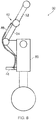
- the actuation device 46 includes a mechanical input device 48, which in the illustrated embodiment is a handle pivotally coupled to a main fitting 50 and arranged to drive the Bowden cable.
- the mechanical input device 48 is arranged to be within the reach of an average human stood at an operating location on the ground when the landing gear assembly is in the deployed condition. As such, the ground lock 40 can be operated using the input device 48.
- the operating location may be adjacent to a lower portion of the landing gear assembly, for example, a wheel.
- the landing gear assembly 30 may include a biasing device (not shown) arranged to bias the actuation device 46 to a unlocked condition corresponding to the second part being in the unlocked condition; for example, a spring may be provided to force the mechanical input device to an unlocked condition.
- a removable lock element (not shown) may be provided that is arranged to be engagable with the landing gear assembly to maintain the actuation device 46 in a locked condition corresponding to the second part being in the locked condition.
- the ground lock 40 includes an indicator element 44a which in the illustrated embodiment is a coloured portion of the lever arm 44; the colour may for example be red.
- the indicator element 44a is arranged to move with the second part 42 so as to be visible to a user of the actuation device 46 when the ground lock 40 is in the locked condition in order to provide a visible indication that the ground lock 40 is engaged.
- the indicator element 44a is arranged to be hidden from the user of the actuation device 46 when the ground lock 40 is in the unlocked condition in order to provide a visible indication that the ground lock 40 is disengaged; for example, in the illustrated embodiment the indicator element 44a is hidden behind a cover portion 34a of the second stay arm 34.
- a user When it is desired to engage the ground lock 40, a user operates the actuation device 46 to pivotally move the lever arm 44 from an unlocked position as shown in Figures 3b and 3c , to a locked position as shown in Figure 3a .
- the movement of the lever arm 44 causes corresponding rotation of the second part 42 to move it from the unlocked condition to the locked condition.
- the indicator element When in the locked condition, the indicator element is exposed so as to be visible to the user such that the user can verify that the ground lock 40 is engaged.
- the landing gear assembly provides a simple means by which a user stood on the ground can mechanically operate a ground lock which is situated out of the manual reach of the user.
- ground lock 40 in the illustrated embodiment is similar to the lock 10 of Figures 2a to 2c
- the ground lock may take any suitable form in which ground lock is mechanically coupled to the landing gear assembly and to a mechanical actuation device for mechanical operation by a user from an operating location on the ground;
- the first part may comprise a lock link arm with a hole through it and the second part may comprise a bolt or pin movably mounted on the landing gear and movable into an out of the hole by the actuation device, the landing gear bearing arranged such that the holes of both lock link arms are coaxially aligned when the landing gear is in a deployed condition.
- the actuation device may be coupled to a pawl operating in a similar manner to pawl 110 in Figure 1 , with or without a biasing force B.
- the first and/or second part may be formed of any suitable material, such as metal, a hard plastics material, or a composite material; steel or titanium are preferred materials.
- the lock according to embodiments of the invention does not attempt to engage and jam the gear when retracted or in transit in the air; for example, the generally circular arrangement acts as a means of baulking the ground lock when the gear is not in the downlocked position.
Description
- It is known for a vehicle assembly to include a lock arranged to maintain a first part of the assembly in a particular position with respect to a second part of the assembly.
- An example of such a vehicle assembly is an aircraft landing gear assembly, which may include a down lock and a ground lock.
- The purpose of a down lock is to lock a landing gear assembly in a deployed condition. An actuator may be provided to unlock the down lock, thereby enabling the landing gear assembly to move to a stowed condition. Accidental actuation of the down lock actuator when the aircraft is on the ground can result in the aircraft fuselage striking the ground. As such, it is common to provide a ground lock to inhibit unlocking of the down lock while the ground lock is in a locked condition. A ground lock is generally a simple mechanical lock. In one example, the arms of a lock link are each provided with a hole, the holes being located so as to become coaxially aligned when the landing gear is in a deployed condition. A pin is manually inserted into the holes to inhibit articulation of the lock link, thereby inhibiting retraction of the landing gear. Prior to take off, a user may remove the pin such that the landing gear can be stowed following takeoff.
- Ground lock accessibility is therefore a consideration at the design stage of a landing gear assembly. The present inventor has identified that this can result in a landing gear assembly receiving a sub optimal geometry.
- Known vehicle assembly locks can also be adversely affected by movement of the vehicle assembly in use. To address this problem, it is known to provide a substantial biasing device, such as a spring, to maintain the lock in a particular condition while the vehicle assembly is moving.
-
GB 592591 - However, the present inventor has identified that the size and/or mass of such biasing devices can be reduced, and in some cases eliminated.
- According to a first aspect of the invention, there is provided a landing gear assembly according to claim 1.
- Thus, the second part i.e. locking element has a size and proportion for enabling insertion through a lug hole in a member of the vehicle assembly, rather than requiring a separate pivot pin. In embodiments of the invention this results in the second part defining a relatively large bearing in comparison to the pawl of
Figure 1 , resulting in relatively high friction to resist movement in use. - The second part, or a lock subassembly of which it forms a part, may be substantially mass balanced about the pivot axis of the second part.
- In embodiments of the invention, the second part bearing friction moment may substantially resist movement due to inertia moment. For example, the coefficient of friction may be within the range 0.05 to 0.45, in some embodiments within the range of 0.1 to 0.25 and in some embodiments within the range of 0.15 to 0.2.
- The distance between the centre of mass of the second part and the pivot axis will be referred to as the "Cg offset". The Cg offset is preferably less than 50% of the effective bearing radius, more preferably less than 45%, even more preferably less than 25%, even more preferably less than 10% and even more preferably less than 5%.
- The entire swept volume may define the locking region of the swept volume.
- The lock may be arranged such that, with the second part in the unlocked condition the second engagement surface is outside of the swept volume.
- The lock may include a biasing device arranged to bias the second part to remain in one or more of the locked condition and the unlocked condition. Advantageously, the biasing force required may be reduced relative to known arrangements due to the second part being substantially mass balanced about the pivot axis.
- The biasing device may comprise a sprung detent arranged to hold the second part in a locked or unlocked position once it is in that position.
- The lock geometry may inhibit the lock engaging when the first part is out of the lockable position, for example when the gear is retracted or in transit, but when the gear is in a down position the lock may be engaged or disengaged at will. The detent(s) may hold the second part in either or both positions, since when on the ground it is sometimes preferred that the lock does not accidentally engage, and at other times that it does not accidentally disengage.
- The second part may define a generally circular major peripheral surface portion which extends around the pivot axis of the second part and which defines the second engagement surface.
- The first part may include a recessed surface which defines the first engagement surface. Such embodiments of the invention are advantageous in comparison to a pawl 'finger style' lock in that the locking elements, which can extend along a major portion of a shaft, react shear and bending loads.
- The second part may include a recessed surface which defines a passageway for movement of the first part when the second part is in the unlocked condition.
- The recessed surface of the first and/or second part may have an arc shaped cross section through a plane which is orthogonal with respect to the pivot axis.
- The radius of a peripheral surface portion of the first part may correspond or generally equate to the radius of the recessed surface of the second part. This may minimise the amount of unbalance provided by the recess.
- The radius of a peripheral surface portion of the second part may correspond or generally equate to the radius of the recessed surface of the first part.
- The first and/or second engagement surface may include a ramped or stepped region. This may permit the lock to partially engage when the first part is slightly out of the engagement position for locking.
- Embodiments of the invention will now be described with reference to the accompanying drawings, in which:
-
Figure 1 is a schematic diagram of a known landing gear assembly; -
Figures 2a and 2b are schematic diagrams of a lock according to an embodiment of the invention; -
Figure 3 is a schematic diagram illustrating the centre of mass, bearing radius and centre of rotation of the second part; -
Figure 4 is a schematic diagram illustrating bearing portions of the second part which are of different radii with respect to the locking portion of the second part; -
Figures 5a to 5c are schematic diagrams of part of a aircraft landing gear assembly according to an embodiment of the invention; and -
Figure 6 is a schematic diagram of the landing gear assembly ofFigures 5a to 5c . -
Figure 1 is schematic diagram of a knownlanding gear assembly 100 including adown lock 102. Theassembly 100 includes afirst stay arm 104 pivotally coupled to asecond stay arm 106 via apivot pin 108. Thestay arms - The
down lock 102 is formed by apawl 110 pivotally coupled to thefirst stay arm 104 via apivot pin 112 and biased towards astop protrusion 114 by aspring 116 acting in tension to apply a biasing force B. When thepawl 110 is held against thestop protrusion 114, thepawl 110 is in a locked condition because anend face 110a adjacently opposes acorresponding shoulder face 106a of thesecond stay arm 106 such that attempted movement of thesecond stay arm 106 relative to thefirst stay arm 104 aboutpivot 108 in the direction of arrow U is axially reacted by thepawl 110. - The
pawl 110 can be moved by an actuator (not shown) in the direction of arrow DU to unlock thedown lock 102 such that thestay arms landing gear assembly 102 being in a stowed condition for flight. - In use, parts of the
assembly 100 experience forces, such as centrifugal forces or acceleration or deceleration forces, urging them to move. Thepawl 102 for example may attempt to move in the direction of arrow DU against the action of thespring 116. Thespring 116 should therefore be appropriately sized to resist such movement because otherwise thedown lock 102 may unintentionally unlock. However, increasing the size of a spring generally results in an increase in weight. -
Figures 2a and 2b schematically illustrate alock 10 according to an embodiment of the present invention. Thelock 10 is suitable for locking a vehicle assembly in a particular condition. - The
lock 10 includes afirst part 12, which may for example be coupled to, or may be a part of, a stay arm, link or brace member. Thefirst part 12 is arranged to pivot about apivot axis 14 as the vehicle assembly changes between first and second conditions; for example, in the case of a landing gear assembly, a deployed condition, in which the landing gear assembly is arranged to support an aircraft on the ground, and a retracted condition for flight. - The
first part 12 has a generally circularperipheral surface 12a surrounding thepivot axis 14. Thus, thefirst part 12 has a generally circular cross section through a plane perpendicular to thepivot axis 14. Theperipheral surface 12a includes a concave, arc-shapedfirst engagement surface 12b, which defines a segment-shaped recess. Rotation of thefirst part 12 about thepivot axis 14 causes thefirst engagement surface 12b to move through a swept volume. - The
lock 10 includes asecond part 16 which is pivotally mounted to rotate about apivot axis 18. Thesecond part 16 is rotatable by an actuation device (not shown) such as an actuator or cable arrangement; in some embodiments the second part may be arranged to be manually moved by a user. - The
second part 16 has a generally circularperipheral surface 16a surrounding thepivot axis 18. Thus, thesecond part 16 has a generally circular cross section through a plane perpendicular to the axis of thepivot axis 18. In embodiments of the invention this may advantageously enable thesecond part 16 to be formed by a pivot pin or the like. - The
peripheral surface 16a defines a second engagement surface having a radius Re2 that is generally equal to the radius Re1 of thefirst engagement surface 12b such that thefirst engagement surface 12b can matingly receive the circularperipheral surface 16a of thesecond part 16. - The
peripheral surface 16a includes a concave, arc shapedpassage surface 16b, which defines a segment-shaped recess. Thepassage surface 16b has a radius Rp2 that is generally equal to the radius Rp1 of theperipheral surface 12a of thefirst part 12 such that thepassage surface 16b can receive theperipheral surface 12a of thefirst part 12 to permit rotation of thefirst part 12 about thepivot axis 14. - The
second part 16 is rotatable about thepivot axis 18 between an unlocked condition and a locked condition. - In the unlocked condition, as shown in
Figure 2a , thesecond part 16 is orientated with thepassage surface 16b facing thefirst part 12 with the centre point of thepassage surface 16b intersecting a plane which intersects the pivot axes 14, 18. In this condition thesecond part 16 does not spatially overlap the swept volume of thefirst part 12. Thus, when in the unlocked condition, thesecond part 16 permits rotation of thefirst part 12. - In the locked condition, as shown in
Figure 2b , the generally circularperipheral surface 16a enters the segment-shaped recess defining thefirst engagement surface 12b so as to be within a locking portion of the swept volume of thefirst part 12a. Thus, when in the locked condition, theperipheral surface 16a of thesecond part 16 engages the arc shapedfirst engagement surface 12b to inhibit rotation of thefirst part 12. - The second part may assume the locked condition when the
first part 12 is in an engagement condition in which the segment-shaped recess which defines thefirst engagement surface 12b is facing the second part with the centre point of thefirst engagement surface 12b intersecting the plane which intersects the pivot axes 14, 18. In embodiments of the invention the engagement condition may equate to a landing gear assembly being in a deployed condition. - In embodiments of the invention, the first and/or second engagement surface may include a ramped or stepped region; for example, a region defining a surface that is closer to the pivot axis than an adjacent part of the engagement surface. This may permit the lock to partially engage when the first part is slightly out of the engagement condition for locking.
- A
position biasing device 20 in the form of a spring loaded detent is provided to bias thesecond part 16 to remain in the locked and unlocked conditions. The second part includes twopositioning recesses 16c each arranged to receive the spring loadeddetent 20. One of the positioning recesses 16c is arranged to receive the spring loadeddetent 20 upon the second part being orientated in the locked condition. The other one of the positioning recesses 16c is arranged to receive the spring loadeddetent 20 upon the second part being orientated in the unlocked condition. The actuation device may be used to provide a dominant force relative to the biasing force provided by theposition biasing device 20. - In the illustrated embodiment the
second part 16 has a generally circular cross section perpendicular to its axis of rotation. Imbalance caused by the segment-shaped recess which defines thepassage surface 16b and by the positioning recesses 16c is relatively minor relative to the effective bearing radius and may in some embodiments of the invention be counter-balanced. The lock is arranged such that the friction moment of the second part substantially resists movement due to inertia moment. Any shortfall may be addressed by the detent biasing force. - Referring additionally to
Figures 3 and 4 , the second part includes bearingportions 16f, 16e defining respective bearing surfaces which support thesecond part 16 within thestay arm 34. A lockingportion 16d is disposed between them. The lockingportion 16d defines the second engagement surface and the passage surface. The bearingportions 16f, 16e differ in diameter with respect to the lockingportion 16d. For example, the lockingportion 16d has radius Re2. The bearingportions 16e, 16f have radii Rb1 and Rb2 respectively. In the illustrated embodiment Rb2 is smaller than Re2 and Rb1 is larger than Re2. Thesecond part 16 can be retained in its axial position relative to thestay arm 34 by a number of means familiar to a person skilled in the art; for example, by a nut on the outer end of the second bearing portion 16e (not shown). In another embodiment Rb1 and Rb2 can be the same as Re2, in which case thestay arm 34 would have a single continuous bearing bore to receive Re2, this giving support along the majority of the length ofelement 16. - If the radii Rb1 and Rb2 are equal then this is the effective radius to consider for friction. If the centre of mass Cg of the
second part 16 is mid-way between the bearingportions first bearing portion 16f, for example, then proportionally greater 'weighting' should be given to the radius Rb1 when determining the effective mean radius. The effective bearing radius may be defined as = [(% weight borne on 16f x Rb1) + (% weight borne on 16e x Rb2)] / 100. - The inertia moment of the
second part 16 can be calculated from its mass x acceleration x offset L of the centre of mass axis Cg from thepivot axis 18. The offset L of the centre of mass axis Cg from thepivot axis 18 will be referred to as the "Cg offset". Thus, inertia moment = M · a · L. The general cross sectional area of thesecond part 16 is similar in size to its effective bearing radius. As such, even with a substantial segment-shaped recess defined by thepassage surface 16b (illustrated inFigures 2a and 2b ), the centre of mass Cg of thesecond part 16 is relatively close to thepivot axis 18 in comparison to the effective bearing radius. - The friction moment of the second part can be calculated by radial force x coefficient of friction x second part effective mean rotational bearing radius Rb. Thus, friction moment = F · µ · R, where F is given by mass x acceleration = M · a.
- Therefore, the
second part 16 will remain still without a detent if M · a · µ · R ≥ M · a · L., which may be simplified to µ · R ≥ L. Put another way, the orientation of thesecond part 16 will generally be unaffected by forces arising from vehicle movement if the Cg offset L is no greater than the second part mean rotational bearing radius multiplied by its mean bearing coefficient of friction. Generally speaking, an increase in mass balance of thesecond part 16, results in a decrease in terms of bearing friction and/or detent biasing force required to inhibit rotational movement of thesecond part 16 due to forces arising from movement of the vehicle. - Thus, a lock according to embodiments of the invention may be less likely to rotate due to vehicle movement in comparison to prior art locks. As such, the likelihood of the lock unintentionally changing between the locked and unlocked condition may be reduced. If a biasing device is provided to bias the second part to a particular orientation, the biasing force required may be reduced relative to known arrangements.
- A lock according to embodiments of the invention may take any suitable form and may be used with any suitable vehicle assembly to lock the position of a first part of the assembly relative to a further part of the assembly; for example, a landing gear uplock latch, a door lock, or on a piece of equipment arranged to rotate in use.
- In embodiments where the second part has a generally circular profile, the second part may advantageously be mounted within a lug or the like, rather than requiring a separate pivot pin.
-
Figures 5a to 5c show an aircraftlanding gear assembly 30 according to an embodiment of the present invention. - The
landing gear assembly 30 includes a foldable stay having afirst stay arm 32 and asecond stay arm 34 pivotally connected via apivot pin 36. The stay arms move pivotally with respect to one another as the landing gear assembly moves between a deployed condition, in which thelanding gear assembly 30 is arranged to support an aircraft on the ground, and a retracted condition for flight. In the deployed condition, thestay arms Figure 5a . As the landing gear assembly moves towards the stowed condition, thestay arms Figure 5c . - The
landing gear assembly 30 includes aground lock 40. Theground lock 40 in the illustrated embodiment is similar to thelock 10 described with reference toFigures 2a and 2b ; as such, for brevity, only a brief description will be provided. - The
ground lock 40 includes afirst part 32a, defined by the end of thefirst stay arm 32 which is closest to thepivot pin 36, and asecond part 42 which is pivotally coupled to thesecond stay arm 34 close to thepivot pin 36. - Referring additionally to
Figure 6 , anactuation device 46 is operable to rotate thesecond part 42 to enable mechanical operation of theground lock 40 by a user from an adjacent location on the ground. In the illustrated embodiment the actuation device is a Bowden cable, but in other embodiments may take any suitable form. Thesecond part 42 may be coupled to alever arm 44 that is attached to anactuation device 46 such that the load path of an applied turning force acts through thelever arm 44 to provide mechanical advantage to theactuation device 46. - The
actuation device 46 is operable to move thesecond part 42 between a locked condition, in which thesecond part 42 engages the first part to inhibit movement of thelanding gear assembly 30 from the deployed condition to the retracted condition, and a non-locking condition, in which thesecond part 42 permits movement of the landing gear assembly from the deployed condition to the retracted condition due to thesecond part 42 not residing within the swept volume of thefirst part 32a. - The
actuation device 46 includes amechanical input device 48, which in the illustrated embodiment is a handle pivotally coupled to amain fitting 50 and arranged to drive the Bowden cable. Themechanical input device 48 is arranged to be within the reach of an average human stood at an operating location on the ground when the landing gear assembly is in the deployed condition. As such, theground lock 40 can be operated using theinput device 48. The operating location may be adjacent to a lower portion of the landing gear assembly, for example, a wheel. - In embodiments of the invention the
landing gear assembly 30 may include a biasing device (not shown) arranged to bias theactuation device 46 to a unlocked condition corresponding to the second part being in the unlocked condition; for example, a spring may be provided to force the mechanical input device to an unlocked condition. In such embodiments, a removable lock element (not shown) may be provided that is arranged to be engagable with the landing gear assembly to maintain theactuation device 46 in a locked condition corresponding to the second part being in the locked condition. Thus, the pilot can feel assured that the ground lock is disengaged by viewing the removed lock element. - The
ground lock 40 includes anindicator element 44a which in the illustrated embodiment is a coloured portion of thelever arm 44; the colour may for example be red. Theindicator element 44a is arranged to move with thesecond part 42 so as to be visible to a user of theactuation device 46 when theground lock 40 is in the locked condition in order to provide a visible indication that theground lock 40 is engaged. Theindicator element 44a is arranged to be hidden from the user of theactuation device 46 when theground lock 40 is in the unlocked condition in order to provide a visible indication that theground lock 40 is disengaged; for example, in the illustrated embodiment theindicator element 44a is hidden behind acover portion 34a of thesecond stay arm 34. - In use, when it is desired to engage the
ground lock 40, a user operates theactuation device 46 to pivotally move thelever arm 44 from an unlocked position as shown inFigures 3b and 3c , to a locked position as shown inFigure 3a . The movement of thelever arm 44 causes corresponding rotation of thesecond part 42 to move it from the unlocked condition to the locked condition. When in the locked condition, the indicator element is exposed so as to be visible to the user such that the user can verify that theground lock 40 is engaged. - Thus, the landing gear assembly according to embodiments of the invention provides a simple means by which a user stood on the ground can mechanically operate a ground lock which is situated out of the manual reach of the user.
- While the
ground lock 40 in the illustrated embodiment is similar to thelock 10 ofFigures 2a to 2c , in other embodiments the ground lock may take any suitable form in which ground lock is mechanically coupled to the landing gear assembly and to a mechanical actuation device for mechanical operation by a user from an operating location on the ground; for example, the first part may comprise a lock link arm with a hole through it and the second part may comprise a bolt or pin movably mounted on the landing gear and movable into an out of the hole by the actuation device, the landing gear bearing arranged such that the holes of both lock link arms are coaxially aligned when the landing gear is in a deployed condition. In other embodiments, the actuation device may be coupled to a pawl operating in a similar manner to pawl 110 inFigure 1 , with or without a biasing force B. - In embodiments of the invention the first and/or second part may be formed of any suitable material, such as metal, a hard plastics material, or a composite material; steel or titanium are preferred materials.
- Advantageously, the lock according to embodiments of the invention does not attempt to engage and jam the gear when retracted or in transit in the air; for example, the generally circular arrangement acts as a means of baulking the ground lock when the gear is not in the downlocked position.
- Although the invention has been described above with reference to one or more preferred embodiments, it will be appreciated that various changes or modifications may be made without departing from the scope of the invention as defined in the appended claims. The word "comprising" can mean "including" or "consisting of" and therefore does not exclude the presence of elements or steps other than those listed in any claim or the specification as a whole.
Claims (9)
- A landing gear assembly comprising:a pivotally mounted first part (12) including a first engagement surface (12b) which defines a swept volume as the first part moves;a pivotally mounted second part (16) including a second engagement surface (16a), the second part being movable between:a locked condition, in which the second engagement surface is within a locking region of the swept volume for engagement with the first engagement surface to inhibit movement of the first part; andan unlocked condition, in which the second engagement surface is outside of the locking region of the swept volume; anda member (34) comprising a pair of lugs disposed in a parallel relationship with a space between them, each lug defining a hole, the holes being coaxially aligned,
wherein the second part including first and second bearing portions (16e, 16f) with a locking portion (16d) between them, the locking portion defining the second engagement surface, the second part being configured to be inserted into and mounted within the lug holes with the locking portion being disposed in the space between the lugs,characterised in that: the lug holes are through holes and the locking portion has a radius not greater than a radius of at least one of the bearing portions. - A landing gear assembly according to claim 1 arranged such that with the second part in the unlocked condition the second engagement surface is outside of the swept volume.
- A landing gear assembly according to any of claims 1 and 2 including a biasing device (20) arranged to bias the second part to remain in one or more of the locked condition and the unlocked condition.
- A landing gear assembly according to any of claims 1 to 3 wherein the second part defines a generally circular major peripheral surface (16a) which extends around the pivot axis of the second part and which defines the second engagement surface.
- A landing gear assembly according to any of claims 1 to 4, wherein the first part includes a recessed surface which defines the first engagement surface.
- A landing gear assembly according to any of claims 1 to 5, wherein the second part includes a recessed surface which defines a passageway for movement of the first part when the second part is in the unlocked condition.
- A landing gear assembly according to claims 5 or 6, wherein the recessed surface of the first part and/or second part is generally arc shaped.
- A landing gear assembly according to claim 7, wherein the radius (Rp1) of a peripheral surface portion of the first part corresponds to the radius (RP2) of the recessed surface of the second part and/or the radius of a peripheral surface portion of the second part corresponds to the radius of the recessed surface of the first part.
- A landing gear assembly according to any of claims 1 to 8, wherein the first and/or second engagement surface includes a ramped or stepped region opening onto the peripheral surface thereof.
Applications Claiming Priority (3)
| Application Number | Priority Date | Filing Date | Title |
|---|---|---|---|
| GB1316101.3A GB2518007C (en) | 2013-09-10 | 2013-09-10 | A lock and aircraft landing gear assembly |
| EP14758631.7A EP3089907B1 (en) | 2013-09-10 | 2014-08-29 | Aircraft landing gear assembly with a ground lock |
| PCT/GB2014/052624 WO2015036730A1 (en) | 2013-09-10 | 2014-08-29 | Aircraft landing gear assembly with a ground lock |
Related Parent Applications (2)
| Application Number | Title | Priority Date | Filing Date |
|---|---|---|---|
| EP14758631.7A Division EP3089907B1 (en) | 2013-09-10 | 2014-08-29 | Aircraft landing gear assembly with a ground lock |
| EP14758631.7A Division-Into EP3089907B1 (en) | 2013-09-10 | 2014-08-29 | Aircraft landing gear assembly with a ground lock |
Publications (2)
| Publication Number | Publication Date |
|---|---|
| EP3566944A1 EP3566944A1 (en) | 2019-11-13 |
| EP3566944B1 true EP3566944B1 (en) | 2021-10-06 |
Family
ID=49487001
Family Applications (3)
| Application Number | Title | Priority Date | Filing Date |
|---|---|---|---|
| EP19182477.0A Active EP3584158B1 (en) | 2013-09-10 | 2014-08-29 | Aircraft landing gear assembly with a ground lock |
| EP19182478.8A Active EP3566944B1 (en) | 2013-09-10 | 2014-08-29 | Aircraft landing gear assembly with a ground lock |
| EP14758631.7A Active EP3089907B1 (en) | 2013-09-10 | 2014-08-29 | Aircraft landing gear assembly with a ground lock |
Family Applications Before (1)
| Application Number | Title | Priority Date | Filing Date |
|---|---|---|---|
| EP19182477.0A Active EP3584158B1 (en) | 2013-09-10 | 2014-08-29 | Aircraft landing gear assembly with a ground lock |
Family Applications After (1)
| Application Number | Title | Priority Date | Filing Date |
|---|---|---|---|
| EP14758631.7A Active EP3089907B1 (en) | 2013-09-10 | 2014-08-29 | Aircraft landing gear assembly with a ground lock |
Country Status (6)
| Country | Link |
|---|---|
| US (2) | US10569863B2 (en) |
| EP (3) | EP3584158B1 (en) |
| CA (3) | CA3124653C (en) |
| ES (3) | ES2755881T3 (en) |
| GB (3) | GB2518007C (en) |
| WO (1) | WO2015036730A1 (en) |
Families Citing this family (4)
| Publication number | Priority date | Publication date | Assignee | Title |
|---|---|---|---|---|
| US10108189B2 (en) * | 2016-07-29 | 2018-10-23 | Ge Aviation Systems Llc | Integrated flight management system and flight director |
| US11608649B2 (en) * | 2020-03-12 | 2023-03-21 | The Boeing Company | Locking mechanism for fall protection |
| CN112455645B (en) * | 2020-12-14 | 2022-11-29 | 珠海紫燕新科技有限公司 | Collapsible unmanned aerial vehicle |
| US11613386B1 (en) * | 2022-03-30 | 2023-03-28 | Jalal Bolouri | Vertical landing apparatus and method |
Family Cites Families (48)
| Publication number | Priority date | Publication date | Assignee | Title |
|---|---|---|---|---|
| GB592591A (en) * | 1944-09-07 | 1947-09-23 | Miles Aircraft Ltd | Improvements in locking devices |
| GB475222A (en) * | 1935-11-23 | 1937-11-16 | Raymond Saulnier | Improvement in landing gear for aircraft |
| GB470928A (en) * | 1936-02-25 | 1937-08-25 | Reginald Alfred Charles Brie | Improvements in and relating to undercarriages for aircraft |
| GB473425A (en) | 1936-03-12 | 1937-10-12 | George Herbert Dowty | Improvements relating to locking and/or indicating means for retractable aircraft undercarriages |
| GB514051A (en) | 1937-05-19 | 1939-10-30 | Siam | Improvements in means for locking retractable undercarriages for aircraft |
| GB537464A (en) | 1938-12-06 | 1941-06-24 | Olaer Sa De Materiel Oleo Pneu | Improvements in automatic locking devices for aircraft undercarriages |
| US2423501A (en) | 1942-12-29 | 1947-07-08 | Republic Aviat Corp | Retractable landing gear lock for aircraft |
| US2444319A (en) * | 1944-12-08 | 1948-06-29 | Curtiss Wright Corp | Airplane landing gear |
| US2451265A (en) * | 1945-07-17 | 1948-10-12 | Fairchild Engine & Airplane | Aircraft landing gear lock |
| US2497415A (en) | 1945-09-28 | 1950-02-14 | Arnold G Parker | Self-locking actuating mechanism |
| GB620037A (en) | 1945-12-13 | 1949-03-18 | Electrol Inc | Improvements relating to control units for hydraulic systems |
| GB606079A (en) | 1946-04-10 | 1948-08-05 | Martin James | Operating aircraft landing gear |
| GB627322A (en) | 1946-12-05 | 1949-08-05 | Lines Bros Ltd | Improvements relating to targets, gliders or other objects towed through the air andto aircraft |
| GB626280A (en) * | 1947-08-25 | 1949-07-12 | Electro Hydraulics Ltd | Improvements in or relating to retractable undercarriages for aircraft |
| GB644147A (en) * | 1947-12-18 | 1950-10-04 | Electro Hydraulics Ltd | An improved locking means |
| GB648362A (en) * | 1948-03-04 | 1951-01-03 | Electro Hydraulics Ltd | Locking means for breaking struts |
| US2511528A (en) | 1948-08-05 | 1950-06-13 | United Aircraft Corp | Nose gear down lock |
| GB704080A (en) | 1950-11-17 | 1954-02-17 | Boulton Aircraft Ltd | Improvements in and relating to retractable aircraft undercarriages |
| US2692784A (en) * | 1953-01-21 | 1954-10-26 | Boeing Co | Hinged strut lock |
| US2772060A (en) | 1953-09-03 | 1956-11-27 | Lockheed Aircraft Corp | Actuating and locking mechanism |
| GB993847A (en) | 1961-05-03 | 1965-06-02 | Dunlop Rubber Co | Device for temporarily securing a helicopter to a landing surface |
| US3107886A (en) | 1961-11-09 | 1963-10-22 | Kaman Aircraft Corp | Hydraulic system for aircraft landing gear and hydraulic actuator therefor |
| GB1175097A (en) | 1967-06-21 | 1969-12-23 | Electro Hydraulics Ltd | Retractable Undercarriage for Aircraft |
| GB1327384A (en) | 1969-11-27 | 1973-08-22 | Automotive Prod Co Ltd | Aircraft undercarriage units |
| GB1295710A (en) * | 1970-08-17 | 1972-11-08 | ||
| CH588022A5 (en) * | 1974-09-13 | 1977-05-31 | Wyss Andre | |
| DE2448659A1 (en) * | 1974-10-11 | 1976-04-22 | Automobilove Zavody Np | Easily operated universal joint for adjustable seat backrests - has hollow drive shaft with stepped recess increasing gearing for easier wear resistant operation |
| GB1500003A (en) * | 1975-04-03 | 1978-02-08 | Newman Tonks Ltd | Key retaining assemblies |
| GB8625505D0 (en) * | 1986-10-24 | 1986-11-26 | Dowty Rotol Ltd | Locking mechanisms |
| EP0384919A1 (en) * | 1989-02-27 | 1990-09-05 | Feinmechanische Werke Mainz GmbH | Gripping and locking device for hinged covers and landing gears of aircraft |
| US5022609A (en) | 1990-01-10 | 1991-06-11 | Lockheed Corporation | Landing gear |
| US5333816A (en) | 1992-09-30 | 1994-08-02 | United Technologies Corporation | Aircraft landing gear swivel locking pin having automatic release and reengage |
| US5308023A (en) | 1993-02-08 | 1994-05-03 | Kress Jets, Inc. | Model aircraft retractable landing gear device |
| US6131852A (en) | 1998-02-18 | 2000-10-17 | British Aerospace Public Limited Company | Aircraft undercarriage locking system |
| GB0315941D0 (en) | 2003-07-08 | 2003-08-13 | Smiths Group Plc | Locking mechanisms |
| WO2006081664A1 (en) * | 2005-02-03 | 2006-08-10 | Héroux-Devtek Inc. | Alternative uplock release assembly |
| JP2007230352A (en) | 2006-02-28 | 2007-09-13 | Sumitomo Precision Prod Co Ltd | Landing gear of aircraft |
| FR2915731B1 (en) | 2007-05-03 | 2009-07-03 | Messier Dowty Sa Sa | CONTRAVING LOCKING DEVICE FOR AIRCRAFT INTERRUPTER |
| DE102007032779B4 (en) | 2007-07-13 | 2020-06-18 | Liebherr-Aerospace Lindenberg Gmbh | Locking system and method for operating a locking system |
| CN101918720A (en) * | 2007-12-21 | 2010-12-15 | 梅西埃-道蒂公司 | Landing gear uplock mechanism employing thermal phase-change actuation |
| GB0806025D0 (en) | 2008-04-03 | 2008-05-14 | Healthy Plant Ltd | Actuator |
| US8123161B1 (en) | 2008-06-03 | 2012-02-28 | Hamilton Sundstrand Corporation | Aircraft landing gear unlock actuator |
| GB2467529B (en) * | 2009-01-30 | 2013-03-06 | Hughes Safety Showers Ltd | Frame for a shelter |
| FR2946319B1 (en) * | 2009-06-05 | 2012-11-30 | Messier Dowty Sa | METHOD FOR MANEUVERING A BREAKER COUNTERFRAME |
| FR2960215B1 (en) * | 2010-05-18 | 2012-06-08 | Messier Dowty Sa | DEVICE FOR UNLOCKING A LICENSOR IN A DEPLOYED POSITION AND LIGHTER EQUIPPED WITH SUCH A DEVICE |
| GB2480623A (en) * | 2010-05-25 | 2011-11-30 | Messier Dowty Ltd | Steerable landing gear with locking mechanism |
| CN201745745U (en) * | 2010-07-20 | 2011-02-16 | 中国航空工业集团公司西安飞机设计研究所 | Strut lock mechanism in landing position of airplane landing gear |
| DE102010046735A1 (en) | 2010-09-28 | 2012-03-29 | Liebherr-Aerospace Lindenberg Gmbh | Locking system and circuit device for a locking system |
-
2013
- 2013-09-10 GB GB1316101.3A patent/GB2518007C/en active Active
- 2013-09-10 GB GB1501925.0A patent/GB2523901B/en active Active
- 2013-09-10 GB GB1501842.7A patent/GB2523899B/en active Active
-
2014
- 2014-08-29 CA CA3124653A patent/CA3124653C/en active Active
- 2014-08-29 ES ES14758631T patent/ES2755881T3/en active Active
- 2014-08-29 WO PCT/GB2014/052624 patent/WO2015036730A1/en active Application Filing
- 2014-08-29 CA CA2922878A patent/CA2922878C/en active Active
- 2014-08-29 EP EP19182477.0A patent/EP3584158B1/en active Active
- 2014-08-29 EP EP19182478.8A patent/EP3566944B1/en active Active
- 2014-08-29 ES ES19182477T patent/ES2883646T3/en active Active
- 2014-08-29 EP EP14758631.7A patent/EP3089907B1/en active Active
- 2014-08-29 ES ES19182478T patent/ES2899116T3/en active Active
- 2014-08-29 US US14/916,867 patent/US10569863B2/en active Active
- 2014-08-29 CA CA3124647A patent/CA3124647C/en active Active
-
2019
- 2019-11-22 US US16/691,985 patent/US11242137B2/en active Active
Non-Patent Citations (1)
| Title |
|---|
| None * |
Also Published As
| Publication number | Publication date |
|---|---|
| EP3584158B1 (en) | 2021-06-16 |
| EP3566944A1 (en) | 2019-11-13 |
| GB2523899A (en) | 2015-09-09 |
| GB2518007C (en) | 2015-12-09 |
| CA2922878C (en) | 2021-09-07 |
| US10569863B2 (en) | 2020-02-25 |
| GB2523899B (en) | 2016-01-20 |
| GB2518007A (en) | 2015-03-11 |
| EP3584158A1 (en) | 2019-12-25 |
| WO2015036730A1 (en) | 2015-03-19 |
| ES2755881T3 (en) | 2020-04-24 |
| CA3124647C (en) | 2023-06-27 |
| GB2518007B (en) | 2015-11-04 |
| US20160221667A1 (en) | 2016-08-04 |
| GB201316101D0 (en) | 2013-10-23 |
| US20200086980A1 (en) | 2020-03-19 |
| CA3124647A1 (en) | 2015-03-19 |
| EP3089907A1 (en) | 2016-11-09 |
| CA3124653C (en) | 2023-05-09 |
| US11242137B2 (en) | 2022-02-08 |
| GB2523901B (en) | 2016-01-20 |
| CA2922878A1 (en) | 2015-03-19 |
| CA3124653A1 (en) | 2015-03-19 |
| GB201501842D0 (en) | 2015-03-18 |
| GB2523901A (en) | 2015-09-09 |
| GB201501925D0 (en) | 2015-03-25 |
| ES2899116T3 (en) | 2022-03-10 |
| EP3089907B1 (en) | 2019-10-02 |
| ES2883646T3 (en) | 2021-12-09 |
Similar Documents
| Publication | Publication Date | Title |
|---|---|---|
| US11242137B2 (en) | Lock and aircraft landing gear assembly | |
| US8864185B2 (en) | Latch with adjustable handle | |
| JPH11512366A (en) | Energy-absorbing landing gear / tailpipe slider including means for indicating the magnitude of the impact load | |
| EP1927767B1 (en) | Improved safety carabiner | |
| US9970223B2 (en) | Articulating prop | |
| CN101802329A (en) | Security handle for vehicles | |
| US10526064B2 (en) | Actuating system for an actuatable door and an actuatable door having such an actuating system | |
| US8272101B2 (en) | Door hinge and door arrangement | |
| MX2014014745A (en) | Door latch assembly. | |
| EP2013431B1 (en) | Door assembly | |
| CN106337611A (en) | Inertia Lock For Vehicle Latch | |
| US20220034127A1 (en) | Opening control device with reversible and irreversible inertial safety locking | |
| US10072446B2 (en) | Door handle unit having a safety function | |
| US20090101754A1 (en) | Aircraft nose gear control apparatus | |
| CN111232180B (en) | Aircraft cabin door gust wind lock device | |
| EP3345825B1 (en) | Latch system with position hold | |
| US20100275661A1 (en) | Operational Device for Lock | |
| US20230258033A1 (en) | Bistable mechanism for an aircraft door | |
| US20240018802A1 (en) | Handle Assembly for Escape Hatch | |
| WO2021084423A1 (en) | Aircraft door handle with limited applicable load |
Legal Events
| Date | Code | Title | Description |
|---|---|---|---|
| PUAI | Public reference made under article 153(3) epc to a published international application that has entered the european phase |
Free format text: ORIGINAL CODE: 0009012 |
|
| STAA | Information on the status of an ep patent application or granted ep patent |
Free format text: STATUS: THE APPLICATION HAS BEEN PUBLISHED |
|
| AC | Divisional application: reference to earlier application |
Ref document number: 3089907 Country of ref document: EP Kind code of ref document: P |
|
| AK | Designated contracting states |
Kind code of ref document: A1 Designated state(s): AL AT BE BG CH CY CZ DE DK EE ES FI FR GB GR HR HU IE IS IT LI LT LU LV MC MK MT NL NO PL PT RO RS SE SI SK SM TR |
|
| STAA | Information on the status of an ep patent application or granted ep patent |
Free format text: STATUS: REQUEST FOR EXAMINATION WAS MADE |
|
| 17P | Request for examination filed |
Effective date: 20200123 |
|
| RBV | Designated contracting states (corrected) |
Designated state(s): AL AT BE BG CH CY CZ DE DK EE ES FI FR GB GR HR HU IE IS IT LI LT LU LV MC MK MT NL NO PL PT RO RS SE SI SK SM TR |
|
| STAA | Information on the status of an ep patent application or granted ep patent |
Free format text: STATUS: EXAMINATION IS IN PROGRESS |
|
| 17Q | First examination report despatched |
Effective date: 20200828 |
|
| STAA | Information on the status of an ep patent application or granted ep patent |
Free format text: STATUS: EXAMINATION IS IN PROGRESS |
|
| GRAP | Despatch of communication of intention to grant a patent |
Free format text: ORIGINAL CODE: EPIDOSNIGR1 |
|
| STAA | Information on the status of an ep patent application or granted ep patent |
Free format text: STATUS: GRANT OF PATENT IS INTENDED |
|
| RIC1 | Information provided on ipc code assigned before grant |
Ipc: B64C 25/26 20060101AFI20210329BHEP Ipc: B64C 25/20 20060101ALI20210329BHEP Ipc: E05D 11/10 20060101ALI20210329BHEP Ipc: F16H 25/18 20060101ALI20210329BHEP Ipc: F16H 27/06 20060101ALI20210329BHEP Ipc: E05B 57/00 20060101ALN20210329BHEP |
|
| RIC1 | Information provided on ipc code assigned before grant |
Ipc: B64C 25/26 20060101AFI20210415BHEP Ipc: B64C 25/20 20060101ALI20210415BHEP Ipc: E05D 11/10 20060101ALI20210415BHEP Ipc: F16H 25/18 20060101ALI20210415BHEP Ipc: F16H 27/06 20060101ALI20210415BHEP Ipc: E05B 57/00 20060101ALN20210415BHEP |
|
| INTG | Intention to grant announced |
Effective date: 20210429 |
|
| GRAS | Grant fee paid |
Free format text: ORIGINAL CODE: EPIDOSNIGR3 |
|
| GRAA | (expected) grant |
Free format text: ORIGINAL CODE: 0009210 |
|
| STAA | Information on the status of an ep patent application or granted ep patent |
Free format text: STATUS: THE PATENT HAS BEEN GRANTED |
|
| AC | Divisional application: reference to earlier application |
Ref document number: 3089907 Country of ref document: EP Kind code of ref document: P |
|
| AK | Designated contracting states |
Kind code of ref document: B1 Designated state(s): AL AT BE BG CH CY CZ DE DK EE ES FI FR GB GR HR HU IE IS IT LI LT LU LV MC MK MT NL NO PL PT RO RS SE SI SK SM TR |
|
| REG | Reference to a national code |
Ref country code: GB Ref legal event code: FG4D |
|
| REG | Reference to a national code |
Ref country code: CH Ref legal event code: EP Ref country code: AT Ref legal event code: REF Ref document number: 1436020 Country of ref document: AT Kind code of ref document: T Effective date: 20211015 |
|
| REG | Reference to a national code |
Ref country code: DE Ref legal event code: R096 Ref document number: 602014080593 Country of ref document: DE |
|
| REG | Reference to a national code |
Ref country code: IE Ref legal event code: FG4D |
|
| REG | Reference to a national code |
Ref country code: LT Ref legal event code: MG9D |
|
| REG | Reference to a national code |
Ref country code: NL Ref legal event code: MP Effective date: 20211006 |
|
| REG | Reference to a national code |
Ref country code: ES Ref legal event code: FG2A Ref document number: 2899116 Country of ref document: ES Kind code of ref document: T3 Effective date: 20220310 |
|
| REG | Reference to a national code |
Ref country code: AT Ref legal event code: MK05 Ref document number: 1436020 Country of ref document: AT Kind code of ref document: T Effective date: 20211006 |
|
| PG25 | Lapsed in a contracting state [announced via postgrant information from national office to epo] |
Ref country code: RS Free format text: LAPSE BECAUSE OF FAILURE TO SUBMIT A TRANSLATION OF THE DESCRIPTION OR TO PAY THE FEE WITHIN THE PRESCRIBED TIME-LIMIT Effective date: 20211006 Ref country code: LT Free format text: LAPSE BECAUSE OF FAILURE TO SUBMIT A TRANSLATION OF THE DESCRIPTION OR TO PAY THE FEE WITHIN THE PRESCRIBED TIME-LIMIT Effective date: 20211006 Ref country code: FI Free format text: LAPSE BECAUSE OF FAILURE TO SUBMIT A TRANSLATION OF THE DESCRIPTION OR TO PAY THE FEE WITHIN THE PRESCRIBED TIME-LIMIT Effective date: 20211006 Ref country code: BG Free format text: LAPSE BECAUSE OF FAILURE TO SUBMIT A TRANSLATION OF THE DESCRIPTION OR TO PAY THE FEE WITHIN THE PRESCRIBED TIME-LIMIT Effective date: 20220106 Ref country code: AT Free format text: LAPSE BECAUSE OF FAILURE TO SUBMIT A TRANSLATION OF THE DESCRIPTION OR TO PAY THE FEE WITHIN THE PRESCRIBED TIME-LIMIT Effective date: 20211006 |
|
| PG25 | Lapsed in a contracting state [announced via postgrant information from national office to epo] |
Ref country code: IS Free format text: LAPSE BECAUSE OF FAILURE TO SUBMIT A TRANSLATION OF THE DESCRIPTION OR TO PAY THE FEE WITHIN THE PRESCRIBED TIME-LIMIT Effective date: 20220206 Ref country code: SE Free format text: LAPSE BECAUSE OF FAILURE TO SUBMIT A TRANSLATION OF THE DESCRIPTION OR TO PAY THE FEE WITHIN THE PRESCRIBED TIME-LIMIT Effective date: 20211006 Ref country code: PT Free format text: LAPSE BECAUSE OF FAILURE TO SUBMIT A TRANSLATION OF THE DESCRIPTION OR TO PAY THE FEE WITHIN THE PRESCRIBED TIME-LIMIT Effective date: 20220207 Ref country code: PL Free format text: LAPSE BECAUSE OF FAILURE TO SUBMIT A TRANSLATION OF THE DESCRIPTION OR TO PAY THE FEE WITHIN THE PRESCRIBED TIME-LIMIT Effective date: 20211006 Ref country code: NO Free format text: LAPSE BECAUSE OF FAILURE TO SUBMIT A TRANSLATION OF THE DESCRIPTION OR TO PAY THE FEE WITHIN THE PRESCRIBED TIME-LIMIT Effective date: 20220106 Ref country code: NL Free format text: LAPSE BECAUSE OF FAILURE TO SUBMIT A TRANSLATION OF THE DESCRIPTION OR TO PAY THE FEE WITHIN THE PRESCRIBED TIME-LIMIT Effective date: 20211006 Ref country code: LV Free format text: LAPSE BECAUSE OF FAILURE TO SUBMIT A TRANSLATION OF THE DESCRIPTION OR TO PAY THE FEE WITHIN THE PRESCRIBED TIME-LIMIT Effective date: 20211006 Ref country code: HR Free format text: LAPSE BECAUSE OF FAILURE TO SUBMIT A TRANSLATION OF THE DESCRIPTION OR TO PAY THE FEE WITHIN THE PRESCRIBED TIME-LIMIT Effective date: 20211006 Ref country code: GR Free format text: LAPSE BECAUSE OF FAILURE TO SUBMIT A TRANSLATION OF THE DESCRIPTION OR TO PAY THE FEE WITHIN THE PRESCRIBED TIME-LIMIT Effective date: 20220107 |
|
| REG | Reference to a national code |
Ref country code: DE Ref legal event code: R097 Ref document number: 602014080593 Country of ref document: DE |
|
| PG25 | Lapsed in a contracting state [announced via postgrant information from national office to epo] |
Ref country code: SM Free format text: LAPSE BECAUSE OF FAILURE TO SUBMIT A TRANSLATION OF THE DESCRIPTION OR TO PAY THE FEE WITHIN THE PRESCRIBED TIME-LIMIT Effective date: 20211006 Ref country code: SK Free format text: LAPSE BECAUSE OF FAILURE TO SUBMIT A TRANSLATION OF THE DESCRIPTION OR TO PAY THE FEE WITHIN THE PRESCRIBED TIME-LIMIT Effective date: 20211006 Ref country code: RO Free format text: LAPSE BECAUSE OF FAILURE TO SUBMIT A TRANSLATION OF THE DESCRIPTION OR TO PAY THE FEE WITHIN THE PRESCRIBED TIME-LIMIT Effective date: 20211006 Ref country code: EE Free format text: LAPSE BECAUSE OF FAILURE TO SUBMIT A TRANSLATION OF THE DESCRIPTION OR TO PAY THE FEE WITHIN THE PRESCRIBED TIME-LIMIT Effective date: 20211006 Ref country code: DK Free format text: LAPSE BECAUSE OF FAILURE TO SUBMIT A TRANSLATION OF THE DESCRIPTION OR TO PAY THE FEE WITHIN THE PRESCRIBED TIME-LIMIT Effective date: 20211006 Ref country code: CZ Free format text: LAPSE BECAUSE OF FAILURE TO SUBMIT A TRANSLATION OF THE DESCRIPTION OR TO PAY THE FEE WITHIN THE PRESCRIBED TIME-LIMIT Effective date: 20211006 |
|
| PLBE | No opposition filed within time limit |
Free format text: ORIGINAL CODE: 0009261 |
|
| STAA | Information on the status of an ep patent application or granted ep patent |
Free format text: STATUS: NO OPPOSITION FILED WITHIN TIME LIMIT |
|
| 26N | No opposition filed |
Effective date: 20220707 |
|
| PG25 | Lapsed in a contracting state [announced via postgrant information from national office to epo] |
Ref country code: AL Free format text: LAPSE BECAUSE OF FAILURE TO SUBMIT A TRANSLATION OF THE DESCRIPTION OR TO PAY THE FEE WITHIN THE PRESCRIBED TIME-LIMIT Effective date: 20211006 |
|
| PG25 | Lapsed in a contracting state [announced via postgrant information from national office to epo] |
Ref country code: SI Free format text: LAPSE BECAUSE OF FAILURE TO SUBMIT A TRANSLATION OF THE DESCRIPTION OR TO PAY THE FEE WITHIN THE PRESCRIBED TIME-LIMIT Effective date: 20211006 |
|
| PG25 | Lapsed in a contracting state [announced via postgrant information from national office to epo] |
Ref country code: MC Free format text: LAPSE BECAUSE OF FAILURE TO SUBMIT A TRANSLATION OF THE DESCRIPTION OR TO PAY THE FEE WITHIN THE PRESCRIBED TIME-LIMIT Effective date: 20211006 |
|
| REG | Reference to a national code |
Ref country code: CH Ref legal event code: PL |
|
| PG25 | Lapsed in a contracting state [announced via postgrant information from national office to epo] |
Ref country code: LU Free format text: LAPSE BECAUSE OF NON-PAYMENT OF DUE FEES Effective date: 20220829 Ref country code: LI Free format text: LAPSE BECAUSE OF NON-PAYMENT OF DUE FEES Effective date: 20220831 Ref country code: CH Free format text: LAPSE BECAUSE OF NON-PAYMENT OF DUE FEES Effective date: 20220831 |
|
| REG | Reference to a national code |
Ref country code: BE Ref legal event code: MM Effective date: 20220831 |
|
| PG25 | Lapsed in a contracting state [announced via postgrant information from national office to epo] |
Ref country code: IT Free format text: LAPSE BECAUSE OF FAILURE TO SUBMIT A TRANSLATION OF THE DESCRIPTION OR TO PAY THE FEE WITHIN THE PRESCRIBED TIME-LIMIT Effective date: 20211006 |
|
| PG25 | Lapsed in a contracting state [announced via postgrant information from national office to epo] |
Ref country code: IE Free format text: LAPSE BECAUSE OF NON-PAYMENT OF DUE FEES Effective date: 20220829 |
|
| PG25 | Lapsed in a contracting state [announced via postgrant information from national office to epo] |
Ref country code: BE Free format text: LAPSE BECAUSE OF NON-PAYMENT OF DUE FEES Effective date: 20220831 |
|
| PGFP | Annual fee paid to national office [announced via postgrant information from national office to epo] |
Ref country code: GB Payment date: 20230720 Year of fee payment: 10 Ref country code: ES Payment date: 20230901 Year of fee payment: 10 |
|
| PGFP | Annual fee paid to national office [announced via postgrant information from national office to epo] |
Ref country code: FR Payment date: 20230720 Year of fee payment: 10 Ref country code: DE Payment date: 20230720 Year of fee payment: 10 |
|
| PG25 | Lapsed in a contracting state [announced via postgrant information from national office to epo] |
Ref country code: HU Free format text: LAPSE BECAUSE OF FAILURE TO SUBMIT A TRANSLATION OF THE DESCRIPTION OR TO PAY THE FEE WITHIN THE PRESCRIBED TIME-LIMIT; INVALID AB INITIO Effective date: 20140829 |