EP3566902A1 - Einstellvorrichtung für einen kraftfahrzeugscheinwerfer - Google Patents
Einstellvorrichtung für einen kraftfahrzeugscheinwerfer Download PDFInfo
- Publication number
- EP3566902A1 EP3566902A1 EP18171201.9A EP18171201A EP3566902A1 EP 3566902 A1 EP3566902 A1 EP 3566902A1 EP 18171201 A EP18171201 A EP 18171201A EP 3566902 A1 EP3566902 A1 EP 3566902A1
- Authority
- EP
- European Patent Office
- Prior art keywords
- adjusting device
- adjusting
- verschubachse
- motor vehicle
- vehicle headlight
- Prior art date
- Legal status (The legal status is an assumption and is not a legal conclusion. Google has not performed a legal analysis and makes no representation as to the accuracy of the status listed.)
- Granted
Links
- 230000008878 coupling Effects 0.000 claims abstract description 29
- 238000010168 coupling process Methods 0.000 claims abstract description 29
- 238000005859 coupling reaction Methods 0.000 claims abstract description 29
- 230000005540 biological transmission Effects 0.000 claims abstract description 27
- 238000006073 displacement reaction Methods 0.000 claims description 16
- 230000000694 effects Effects 0.000 claims description 3
- 150000001875 compounds Chemical class 0.000 claims description 2
- 230000000712 assembly Effects 0.000 description 2
- 238000000429 assembly Methods 0.000 description 2
- 230000006978 adaptation Effects 0.000 description 1
- 230000009286 beneficial effect Effects 0.000 description 1
- 238000009434 installation Methods 0.000 description 1
- 238000011900 installation process Methods 0.000 description 1
- 230000013011 mating Effects 0.000 description 1
- 239000007787 solid Substances 0.000 description 1
Images
Classifications
-
- B—PERFORMING OPERATIONS; TRANSPORTING
- B60—VEHICLES IN GENERAL
- B60Q—ARRANGEMENT OF SIGNALLING OR LIGHTING DEVICES, THE MOUNTING OR SUPPORTING THEREOF OR CIRCUITS THEREFOR, FOR VEHICLES IN GENERAL
- B60Q1/00—Arrangement of optical signalling or lighting devices, the mounting or supporting thereof or circuits therefor
- B60Q1/02—Arrangement of optical signalling or lighting devices, the mounting or supporting thereof or circuits therefor the devices being primarily intended to illuminate the way ahead or to illuminate other areas of way or environments
- B60Q1/04—Arrangement of optical signalling or lighting devices, the mounting or supporting thereof or circuits therefor the devices being primarily intended to illuminate the way ahead or to illuminate other areas of way or environments the devices being headlights
- B60Q1/06—Arrangement of optical signalling or lighting devices, the mounting or supporting thereof or circuits therefor the devices being primarily intended to illuminate the way ahead or to illuminate other areas of way or environments the devices being headlights adjustable, e.g. remotely-controlled from inside vehicle
- B60Q1/068—Arrangement of optical signalling or lighting devices, the mounting or supporting thereof or circuits therefor the devices being primarily intended to illuminate the way ahead or to illuminate other areas of way or environments the devices being headlights adjustable, e.g. remotely-controlled from inside vehicle by mechanical means
- B60Q1/0683—Adjustable by rotation of a screw
-
- B—PERFORMING OPERATIONS; TRANSPORTING
- B60—VEHICLES IN GENERAL
- B60Q—ARRANGEMENT OF SIGNALLING OR LIGHTING DEVICES, THE MOUNTING OR SUPPORTING THEREOF OR CIRCUITS THEREFOR, FOR VEHICLES IN GENERAL
- B60Q1/00—Arrangement of optical signalling or lighting devices, the mounting or supporting thereof or circuits therefor
- B60Q1/02—Arrangement of optical signalling or lighting devices, the mounting or supporting thereof or circuits therefor the devices being primarily intended to illuminate the way ahead or to illuminate other areas of way or environments
- B60Q1/04—Arrangement of optical signalling or lighting devices, the mounting or supporting thereof or circuits therefor the devices being primarily intended to illuminate the way ahead or to illuminate other areas of way or environments the devices being headlights
- B60Q1/0408—Arrangement of optical signalling or lighting devices, the mounting or supporting thereof or circuits therefor the devices being primarily intended to illuminate the way ahead or to illuminate other areas of way or environments the devices being headlights built into the vehicle body, e.g. details concerning the mounting of the headlamps on the vehicle body
- B60Q1/0425—Arrangement of optical signalling or lighting devices, the mounting or supporting thereof or circuits therefor the devices being primarily intended to illuminate the way ahead or to illuminate other areas of way or environments the devices being headlights built into the vehicle body, e.g. details concerning the mounting of the headlamps on the vehicle body the housing being swivel mounted on the vehicle body
-
- B—PERFORMING OPERATIONS; TRANSPORTING
- B60—VEHICLES IN GENERAL
- B60Q—ARRANGEMENT OF SIGNALLING OR LIGHTING DEVICES, THE MOUNTING OR SUPPORTING THEREOF OR CIRCUITS THEREFOR, FOR VEHICLES IN GENERAL
- B60Q1/00—Arrangement of optical signalling or lighting devices, the mounting or supporting thereof or circuits therefor
- B60Q1/02—Arrangement of optical signalling or lighting devices, the mounting or supporting thereof or circuits therefor the devices being primarily intended to illuminate the way ahead or to illuminate other areas of way or environments
- B60Q1/04—Arrangement of optical signalling or lighting devices, the mounting or supporting thereof or circuits therefor the devices being primarily intended to illuminate the way ahead or to illuminate other areas of way or environments the devices being headlights
- B60Q1/06—Arrangement of optical signalling or lighting devices, the mounting or supporting thereof or circuits therefor the devices being primarily intended to illuminate the way ahead or to illuminate other areas of way or environments the devices being headlights adjustable, e.g. remotely-controlled from inside vehicle
- B60Q1/076—Arrangement of optical signalling or lighting devices, the mounting or supporting thereof or circuits therefor the devices being primarily intended to illuminate the way ahead or to illuminate other areas of way or environments the devices being headlights adjustable, e.g. remotely-controlled from inside vehicle by electrical means including means to transmit the movements, e.g. shafts or joints
-
- F—MECHANICAL ENGINEERING; LIGHTING; HEATING; WEAPONS; BLASTING
- F21—LIGHTING
- F21S—NON-PORTABLE LIGHTING DEVICES; SYSTEMS THEREOF; VEHICLE LIGHTING DEVICES SPECIALLY ADAPTED FOR VEHICLE EXTERIORS
- F21S41/00—Illuminating devices specially adapted for vehicle exteriors, e.g. headlamps
- F21S41/60—Illuminating devices specially adapted for vehicle exteriors, e.g. headlamps characterised by a variable light distribution
- F21S41/63—Illuminating devices specially adapted for vehicle exteriors, e.g. headlamps characterised by a variable light distribution by acting on refractors, filters or transparent cover plates
-
- F—MECHANICAL ENGINEERING; LIGHTING; HEATING; WEAPONS; BLASTING
- F21—LIGHTING
- F21S—NON-PORTABLE LIGHTING DEVICES; SYSTEMS THEREOF; VEHICLE LIGHTING DEVICES SPECIALLY ADAPTED FOR VEHICLE EXTERIORS
- F21S41/00—Illuminating devices specially adapted for vehicle exteriors, e.g. headlamps
- F21S41/60—Illuminating devices specially adapted for vehicle exteriors, e.g. headlamps characterised by a variable light distribution
- F21S41/67—Illuminating devices specially adapted for vehicle exteriors, e.g. headlamps characterised by a variable light distribution by acting on reflectors
- F21S41/675—Illuminating devices specially adapted for vehicle exteriors, e.g. headlamps characterised by a variable light distribution by acting on reflectors by moving reflectors
-
- B—PERFORMING OPERATIONS; TRANSPORTING
- B60—VEHICLES IN GENERAL
- B60Q—ARRANGEMENT OF SIGNALLING OR LIGHTING DEVICES, THE MOUNTING OR SUPPORTING THEREOF OR CIRCUITS THEREFOR, FOR VEHICLES IN GENERAL
- B60Q2200/00—Special features or arrangements of vehicle headlamps
- B60Q2200/30—Special arrangements for adjusting headlamps, e.g. means for transmitting the movements for adjusting the lamps
- B60Q2200/36—Conjoint adjustments, i.e. a mechanical link allows conjoint adjustment of several units
-
- F—MECHANICAL ENGINEERING; LIGHTING; HEATING; WEAPONS; BLASTING
- F21—LIGHTING
- F21W—INDEXING SCHEME ASSOCIATED WITH SUBCLASSES F21K, F21L, F21S and F21V, RELATING TO USES OR APPLICATIONS OF LIGHTING DEVICES OR SYSTEMS
- F21W2102/00—Exterior vehicle lighting devices for illuminating purposes
-
- F—MECHANICAL ENGINEERING; LIGHTING; HEATING; WEAPONS; BLASTING
- F21—LIGHTING
- F21W—INDEXING SCHEME ASSOCIATED WITH SUBCLASSES F21K, F21L, F21S and F21V, RELATING TO USES OR APPLICATIONS OF LIGHTING DEVICES OR SYSTEMS
- F21W2107/00—Use or application of lighting devices on or in particular types of vehicles
- F21W2107/10—Use or application of lighting devices on or in particular types of vehicles for land vehicles
Definitions
- the invention relates to an adjusting device for adjusting at least one optically relevant structural unit of a motor vehicle headlight.
- the invention further relates to a motor vehicle headlight with at least one adjusting device according to the invention.
- a relevant structural unit is, for example, a light module, comprising at least one light source, at least one reflector, at least one lens, etc .; but it can also be individual components such as reflectors, lenses, etc., which are adjusted accordingly.
- the at least one optically relevant structural unit is often mounted pivotably about one or more axes, for example about a horizontal and / or vertical axis, in the headlight or motor vehicle headlight.
- Adjustment devices for adjusting optically relevant structural units of motor vehicle headlights such as light sources, reflectors and / or lenses, allow adaptation of the light image generated by the headlight to predetermined requirements. This makes it possible to compensate for deviations from target specifications, which are determined, for example, after an installation process of the motor vehicle headlight in a motor vehicle, subsequently by using a setting device.
- a typical task of adjusting devices is to adapt the headlamp range of a motor vehicle headlight, this technical field having become known, in particular, under the term "headlamp leveling" - abbreviated to LWR.
- At least one adjusting device is usually provided, wherein the adjusting device is usually manually operable, for example, includes Adjusting a rotary knob or an adjusting screw whose rotational movement is converted by a suitable mechanism in a linear movement of a sliding element, which is guided in corresponding slideways in the headlight housing slidably.
- An adjustment of the optically relevant assembly such as the support frame to which the assembly is mounted, is mounted in the sliding element, so that when a sliding of the sliding element, the assembly or the support frame are pivoted.
- the at least one adjusting device can be actuated manually or electrically.
- the coupling part is firmly connected to the holder body, preferably with a fastening means, in particular with at least one screw.
- the adjusting device comprises a further adjusting device, which is electrically actuable and has a drive device, and a second actuating element, wherein the drive device is adapted to move the second actuating element along a second Verschubachse, wherein the second actuating element has an end portion has, which end portion is connectable to the coupling part, which coupling part is arranged, upon displacement of the second actuating element along the second Verschubachse a displacement of the first actuating element - in the case of a parallel alignment of the first and the second Verschubachse a rectified displacement of the first actuating element - and thus causing the sliding member along the first Verschubachse.
- first and the second Verschubachse are not arranged parallel to each other, wherein the end portion of the second actuator in a bearing shell - is taken up - so to speak articulated - of the coupling element, so that the coupling part and thereby also the first adjusting element or the sliding member along the first Verschubachse can be moved.
- the coupling member would not move.
- the adjusting element can be designed as an adjusting screw, wherein a portion of the adjusting element or the adjusting screw is at least partially received in a substantially circular, arranged concentrically to the first Verschubachse opening of the transmission element, so that a rotational movement of the transmission element is transmitted to the actuating element.
- the substantially circular opening may be formed, for example, as a hexagonal opening, wherein the portion of the adjusting element, which is received by the transmission element, has a corresponding shape, so that these two elements can mechanically interlock or form a positive force connection.
- the coupling member In a displacement of the second actuating element by the drive means, as described above, the coupling member is moved and thereby also the first adjusting element, wherein the actuating element is pushed out of or into the substantially circular opening of the transmission element - but not completely pushed out.
- the sliding element engages on at least one optically relevant structural unit such that a movement of the sliding element can be converted into a changed alignment of the at least one optically relevant structural unit.
- the optically relevant structural unit may be, for example, diaphragms, light sources, reflectors, lenses, entire light modules or assemblies, etc. It is also possible for an optically relevant structural unit to be accommodated in an adjustment mechanism, for example in a pivotally mounted support frame.
- an adjustment mechanism for example in a pivotally mounted support frame.
- the first and second Verschubachse be aligned parallel to each other.
- the drive device is designed as a servomotor.
- the drive device is designed as an electric motor.
- the end portion of the first actuating element is formed by a ball head arranged concentrically to the displacement axis.
- the end portion of the second actuating element is formed by a ball head arranged concentrically to the Verschubachse.
- the sliding element is set up to engage two optically relevant structural units.
- a fine adjustment of the sliding element along the first Verschubachse is determined by the thread pitch of the threaded portion of the actuating element and the corresponding counter-thread of the guide member, i. that a separate guide part can be provided for each specific thread pitch of an actuating element.
- the guide part is detachably formed on the sliding element. It can also be provided that the guide part and the sliding element are integrally formed.
- the translation of the rotational movement of the transmission element over the thread pitch of the actuating element and the corresponding guide member is determined, and this translation can, as described above, be varied variably by a simple replacement of the actuating element and the guide member, without other components of the adjustment have to be changed.
- the object is also achieved by a motor vehicle headlight with at least one adjusting device according to the invention.
- the holder body is arranged fixed with respect to a housing of the motor vehicle headlight.
- the holder body is firmly connected to a housing of the motor vehicle headlight.
- the housing of the motor vehicle headlight acts as a support body.
- the above-mentioned horizontal or vertical axis refers to a motor vehicle headlight in proper mounting position in a motor vehicle.
- a pivoting of a light module about a vertical axis may be a cornering light.
- a pivoting of a light module about a horizontal axis may, for example, correspond to a headlight range adjustment.
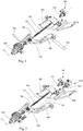
- Fig. 1 shows an exemplary adjustment device for a motor vehicle headlight for adjusting two optically relevant assembly 701, 702 of a motor vehicle headlamp, comprising a manually operable adjusting 100 , which is arranged on a support body 200 , with a rotatably mounted about a first Verschubachse X1 transmission element 150 and with the Transmission member 150 by means of a compound in mechanically engaging first actuator 300th
- the first adjusting element 300 has a threaded portion 310 and an end portion 320, which is formed as a concentric to the first Verschubachse X1 formed ball head, on which end portion 320 is rotatably mounted in a coupling member 400 .
- the adjusting device comprises a sliding element 500, which is displaceably mounted on the mounting body 200 and is adapted to engage the at least one optically relevant structural unit, and a guide element 510 arranged on the sliding element 500 has a headwind corresponding to the threaded section 310 of the first actuating element 300 , wherein the attachable to the threaded portion 310 of the first actuator 300 guide member 510 in combination with the threaded portion 310 is configured to convert a rotational movement of the transmission element 150 in a sliding movement of the sliding member 500 along the Verschubachse X1 .
- the coupling part 400 may be fixedly connected to the mounting body 200 , preferably with a fastening means, in particular at least one screw.
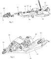
- Fig. 2 shows an exemplary adjusting device for adjusting two optically relevant structural unit of a motor vehicle headlamp, comprising a manually operable adjusting device 100 which is arranged on a support body 200 , with a rotatably mounted about a first Verschubachse X1 transmission element 150 and with the transmission element 150 by means of a connection in mechanically engaging first actuator 300 , wherein the first actuator 300 has a threaded portion 310 and an end portion 320 which is formed as a concentric to the first Verschubachse X1 formed ball head, which end portion 320 is rotatably mounted in a coupling member 400 .
- the adjusting device comprises a sliding element 500 , which is displaceably mounted on the mounting body 200 and is adapted to engage the at least one optically relevant structural unit, and a guide element 510 arranged on the sliding element 500 has a headwind corresponding to the threaded section 310 of the first actuating element 300 , wherein the guide member 510 attachable to the threaded portion 310 of the first actuator 300 is configured in combination with the threaded portion 310 to convert a rotational movement of the transmission member 150 into a sliding movement of the slider 500 along the displacement axis X1 .
- FIG. 2 an electrically actuable adjusting device 600 with a drive device, which can be designed as a servomotor or as an electric motor, and a second control element 610 to see which drive device is set up, the second control element 610 along a second Verschubachse X2 , which is aligned parallel to the first Verschubachse X1 , wherein the second adjusting element 610 has an end section 620 , which end section 620 is connectable to the coupling part 400 as a ball head arranged concentrically to the second displacement axis X2 , which coupling part 400 is set up, with displacement of the second actuating element 620 along the second displacement axis X2 a rectified shift of the first Actuating element 300 and thus of the sliding member 500 along the first Verschubachse X1 effect.
- a drive device which can be designed as a servomotor or as an electric motor
- a second control element 610 to see which drive device is set up, the second control element 610
- the coupling part 400 in which the first adjusting element 300 is rotatably mounted remains at rest, so that only the sliding element 500 undergoes a displacement along the first Verschubachse X1 , wherein the second control element 610 or the electrically actuable adjusting device 600, the coupling member 400, so to speak, fastened or held in peace, while the sliding member 500 is moved by means of the manually operable adjusting device 100 .
- a portion of the adjusting element 300 which is designed as an adjusting screw in the examples shown in the figures, is at least partially accommodated in an assembled condition of the adjusting device in a substantially circular, concentric with the first Verschubachse opening of the transmission element 150 , so that a rotational movement of the transmission element is transmitted to the actuator.
- the substantially circular opening may be formed, for example, as a hexagonal opening, wherein the portion of the adjusting element 300 , which is received by the transmission element 150 , has a corresponding shape, so that these two elements can mechanically interlock or form a positive force connection, in order to transmit the rotational movement of the transmission element 150 to the actuator 300 - this applies to all conceivable forms of the opening of the transmission element 150th
- the coupling part 400 is moved and thereby also the first actuating element 300 , the first actuating element 300 being pushed out of or into the substantially circular opening of the transmission element 150 , however not completely pushed out.
- the guide member 510 which is connected to the first actuator 300 , thereby the sliding member 500 is moved by the same effect, since the mating thread and the corresponding threaded portion of the act first actuator 300 due to the lack of rotation in a sense as a solid connection.
- Fig. 3 shows substantially the same embodiment of the adjusting device of Fig. , wherein the manually operable adjusting device 101 is different. It should be noted that for the example Fig. 2 already described also for the example Fig. 3 is valid.
- Fig. 4 shows an assembled state of the adjusting device Fig. 2 respectively.
- Fig. 3 wherein in addition still a first and a second coupling region 501 , 502 of the sliding element 500 are shown, which areas 501 , 502 are arranged to attack in each case on an optically relevant structural unit, which are not shown in the figures.
- the optically relevant structural unit may be, for example, diaphragms, light sources, reflectors, lenses, entire light modules or assemblies, etc. It is also possible for an optically relevant structural unit to be accommodated in an adjustment mechanism, for example in a pivotally mounted support frame.
- an optically relevant structural unit to be accommodated in an adjustment mechanism, for example in a pivotally mounted support frame.
- an adjustment mechanism for example in a pivotally mounted support frame.
- that the sliding element is adapted to attack the at least one optically relevant structural unit is therefore also understood an arrangement in which the sliding element engages indirectly, for example via an adjustment mechanism on the optically relevant structural unit.
Abstract
Description
- Die Erfindung betrifft eine Einstellvorrichtung zum Einstellen zumindest einer optisch relevanten Baueinheit eines Kraftfahrzeugscheinwerfers.
- Die Erfindung betrifft weiters einen Kraftfahrzeugscheinwerfer mit zumindest einer erfindungsgemäßen Einstellvorrichtung.
- Zur gesetzeskonformen Einstellung des mit einem Scheinwerfer erzeugten Lichtbildes ist es notwendig, dass ein oder mehrere optisch relevante Baueinheiten des Scheinwerfers unter anderem in Höhenrichtung und/ oder seitlich einstellbar sind. Bei einer solchen relevanten Baueinheit handelt es sich beispielsweise um ein Lichtmodul, etwa umfassend zumindest eine Lichtquelle, zumindest einen Reflektor, zumindest eine Linse etc.; es kann sich aber auch um einzelne Bauteile wie Reflektoren, Linsen etc. handeln, die entsprechend verstellt werden.
- Dabei ist die zumindest eine optisch relevante Baueinheit häufig um eine oder mehrere Achsen, beispielsweise um eine horizontale und/ oder vertikale Achse verschwenkbar in dem Scheinwerfer bzw. Kraftfahrzeugscheinwerfer gelagert.
- Einstellvorrichtungen zur Einstellung von optisch relevanten Baueinheiten von Kraftfahrzeugscheinwerfern, wie beispielsweise Lichtquellen, Reflektoren und/ oder Linsen, erlauben eine Anpassung des durch den Scheinwerfer erzeugten Lichtbildes an vorgegebene Anforderungen. Dies erlaubt es, Abweichungen von Sollvorgaben, die beispielsweise nach einem Einbauvorgang des Kraftfahrzeugscheinwerfers in ein Kraftfahrzeug festgestellt werden, nachträglich durch Verwendung einer Einstellvorrichtung ausgleichen zu können.
- Eine typische Aufgabe von Einstellvorrichtungen liegt in der Anpassung der Leuchtweite eines Kraftfahrzeugscheinwerfers, wobei dieses technische Gebiet insbesondere unter dem Ausdruck "Leuchtweitenregulierung" - kurz LWR genannt - bekannt geworden ist.
- Zur Verstellung ist in der Regel zumindest eine Verstelleinrichtung vorgesehen, wobei die Verstelleinrichtung üblicherweise manuell betätigbar ist, beispielsweise umfasst die Verstelleinrichtung ein Drehrad bzw. eine Einstellschraube, deren Drehbewegung über eine geeignete Mechanik in eine Linearbewegung eines Gleitelements umgesetzt wird, welches in entsprechenden Gleitbahnen in dem Scheinwerfergehäuse verschiebbar geführt ist. Ein Verstellpunkt der optisch relevanten Baueinheit, z.B. des Tragerahmens, an welche die Baueinheit angebracht ist, ist in dem Gleitelement gelagert, sodass bei einem Verschieben des Gleitelements die Baueinheit bzw. der Tragerahmen verschwenkt werden.
- Es ist eine Aufgabe der Erfindung eine verbesserte Einstellvorrichtung zur Einstellung einer optisch relevanten Baueinheit eines Kraftfahrzeugscheinwerfers bereitzustellen.
- Diese Aufgabe wird dadurch gelöst, dass die Einstellvorrichtung Folgendes umfasst:
- zumindest eine Verstelleinrichtung, welche an einem Halterungskörper angeordnet ist, mit einem um eine erste Verschubachse drehbar gelagerten Übertragungselement und einem mit dem Übertragungselement mittels einer Verbindung in mechanischem Eingriff stehenden ersten Stellelement, wobei das erste Stellelement einen Gewindeabschnitt und einen Endabschnitt aufweist,
- ein Kopplungsteil, in welchem der Endabschnitt des ersten Stellelements drehbar gelagert ist, wobei das Kopplungsteil bei einer Verstellung durch die zumindest eine Verstelleinrichtung in Bezug auf diese feststehend ist, und
- ein Gleitelement, welches verschiebbar auf dem Halterungskörper gelagert ist und eingerichtet ist, an der zumindest einen optisch relevanten Baueinheit anzugreifen, und ein auf dem Gleitelement angeordnetes Führungsteil mit einem dem Gewindeabschnitt des ersten Stellelements korrespondierendes Gegenwinde, wobei das auf den Gewindeabschnitt des ersten Stellelements anbringbare Führungsteil in Kombination mit dem Gewindeabschnitt eingerichtet ist, eine Drehbewegung des Übertragungselements in eine Schiebebewegung des Gleitelements entlang der Verschubachse zu wandeln.
- Es kann vorgesehen sein, dass die zumindest eine Verstelleinrichtung manuell oder elektrisch betätigbar ist.
- Dabei kann vorgesehen sein, dass das Kopplungsteil mit dem Halterungskörper fest verbunden ist, vorzugsweise mit einem Befestigungsmittel, insbesondere mit zumindest einer Schraube.
- Mit Vorteil kann vorgesehen sein, dass die Einstellvorrichtung eine weitere Verstelleinrichtung, welche elektrisch betätigbar ist und eine Antriebseinrichtung aufweist, und ein zweites Stellelement umfasst, wobei die Antriebseinrichtung eingerichtet ist, das zweite Stellelement entlang einer zweiten Verschubachse zu verschieben, wobei das zweite Stellelement einen Endabschnitt aufweist, welcher Endabschnitt mit dem Kopplungsteil verbindbar ist, welches Kopplungsteil eingerichtet ist, bei einer Verschiebung des zweiten Stellelements entlang der zweiten Verschubachse eine Verschiebung des ersten Stellelements - im Falle einer parallelen Ausrichtung der ersten und der zweiten Verschubachse eine gleichgerichtete Verschiebung des ersten Stellelements - und somit des Gleitelements entlang der ersten Verschubachse zu bewirken.
- Hierbei kann vorgesehen sein, dass die erste und die zweite Verschubachse nicht parallel zueinander angeordnet sind, wobei der Endabschnitt des zweiten Stellelements in einer Lagerschale - gewissermaßen gelenkartig - des Kopplungselements aufgenommen ist, sodass das Kopplungsteil und dadurch auch das erste Stellelement bzw. das Gleitelement entlang der ersten Verschubachse verschoben werden kann. Bei einer nicht gelenkartigen Verbindung zwischen dem zweiten Stellelement und dem Kopplungselement - gemäß dem Fall einer nicht parallelen Ausrichtung der ersten und der zweiten Verschubachse - würde sich das Kopplungsteil nicht verschieben lassen.
- Das Stellelement kann als Stellschraube ausgebildet sein, wobei ein Abschnitt des Stellelements bzw. der Stellschraube zumindest teilweise in einer im Wesentlichen kreisförmigen, konzentrisch zur ersten Verschubachse angeordneten Öffnung des Übertragungselementes aufgenommen ist, sodass eine Drehbewegung des Übertragungselements auf das Stellelement übertragen wird.
- Die im Wesentlichen kreisförmige Öffnung kann beispielsweise als Sechskant-Öffnung ausgebildet sein, wobei der Abschnitt des Stellelements, welcher von dem Übertragungselement aufgenommen wird, eine dazu korrespondierende Form aufweist, sodass diese beiden Elemente mechanisch ineinander greifen können bzw. eine formschlüssige Kraftverbindung bilden können.
- Bei einer Verschiebung des zweiten Stellelements durch die Antriebseinrichtung wird, wie bereits beschrieben, das Kopplungsteil bewegt und dadurch auch das erste Stellelement, wobei das Stellelement hierbei aus bzw. in die im Wesentlichen kreisförmige Öffnung des Übertragungselements geschoben wird - jedoch nicht vollständig herausgeschoben.
- Weiters greift das Gleitelement dergestalt an zumindest einer optisch relevanten Baueinheit an, dass eine Bewegung des Gleitelements in eine geänderte Ausrichtung der zumindest einen optisch relevanten Baueinheit gewandelt werden kann. Bei der optisch relevanten Baueinheit kann es sich beispielsweise um Blenden(anordnungen), Lichtquellen, Reflektoren, Linsen, ganze Lichtmodule bzw. Baugruppen, etc. handeln. Ebenso ist es möglich, dass eine optisch relevante Baueinheit in einer Verstellmechanik, beispielsweise in einem schwenkbar gelagerten Tragerahmen, aufgenommen ist. Unter dem Ausdruck "dass das Gleitelement dazu eingerichtet ist, an der zumindest einen optisch relevanten Baueinheit anzugreifen" wird daher auch eine Anordnung verstanden, in der das Gleitelement indirekt, beispielsweise über eine Verstellmechanik an der optisch relevanten Baueinheit angreift.
- Vorteilhafterweise können die erste und die zweite Verschubachse parallel zueinander ausgerichtet sein.
- Es kann vorgesehen sein, dass die Antriebsvorrichtung als Stellmotor ausgebildet ist.
- Ebenso kann vorgesehen sein, dass die Antriebsvorrichtung als Elektromotor ausgebildet ist.
- Mit Vorteil kann vorgesehen sein, wenn der Endabschnitt des ersten Stellelements durch einen konzentrisch zur Verschubachse angeordneten Kugelkopf gebildet ist.
- Ebenso kann es günstig sein, wenn der Endabschnitt des zweiten Stellelements durch einen konzentrisch zur Verschubachse angeordneten Kugelkopf gebildet ist.
- In einer zweckmäßigen Ausführungsform kann vorgesehen sein, dass das Gleitelement eingerichtet ist, um an zwei optisch relevanten Baueinheiten anzugreifen.
- Eine Feinjustierung des Gleitelements entlang der ersten Verschubachse wird durch die Gewindesteigung des Gewindeabschnitts des Stellelements und des dazu korrespondierenden Gegengewindes des Führungsteils bestimmt, d.h. dass für jede bestimmte Gewindesteigung eines Stellelements ein eigenes Führungsteil vorgesehen sein kann.
- Hierzu kann vorgesehen sein, dass das Führungsteil lösbar an dem Gleitelement ausgebildet ist. Es kann auch vorgesehen sein, dass das Führungsteil und das Gleitelement einstückig ausgebildet sind.
- Mit anderen Worten ist die Übersetzung der Drehbewegung des Übertragungselements über die Gewindesteigung des Stellelements und dem dazu korrespondierenden Führungsteil bestimmt, und diese Übersetzung kann, wie oben beschrieben, durch ein einfaches Austauschen des Stellelements und des Führungsteils variabel verändert werden, ohne dass andere Komponenten der Einstellvorrichtung verändert werden müssen.
- Die Aufgabe wird ebenso durch einen Kraftfahrzeugscheinwerfer mit zumindest einer erfindungsgemäßen Einstellvorrichtung gelöst.
- Dabei kann es günstig sein, wenn der Halterungskörper in Bezug auf ein Gehäuse des Kraftfahrzeugscheinwerfers feststehend angeordnet ist.
- Es kann auch vorgesehen sein, dass der Halterungskörper mit einem Gehäuse des Kraftfahrzeugscheinwerfers fest verbunden ist.
- Weiters kann vorgesehen sein, dass das Gehäuse des Kraftfahrzeugscheinwerfers als Halterungskörper fungiert.
- Je nach Einbaulage der Einstellvorrichtung in einem Kraftfahrzeugscheinwerfer bewirkt eine Verschiebung des Gleitelements entlang der ersten Verschubachse eine Verstellung bzw. Verschwenkung des zumindest einen optisch relevanten Bauteils um eine horizontale oder vertikale Achse.
- Die oben erwähnte horizontale bzw. vertikale Achse bezieht sich dabei auf einen Kraftfahrzeugscheinwerfer in ordnungsgemäßer Einbaulage in einem Kraftfahrzeug. Beispielsweise kann eine Verschwenkung eines Lichtmoduls um eine vertikale Achse ein Kurvenlicht sein. Eine Verschwenkung eines Lichtmoduls um eine horizontale Achse kann beispielsweise einer Leuchtweiteregulierung entsprechen.
- Nachfolgend wird die Erfindung anhand von beispielhaften Zeichnungen näher erläutert. Hierbei zeigt
-
Fig. 1 eine Explosionsansicht eine beispielhaften Ausführungsform einer Einstellvorrichtung, -
Fig. 2 ein weiteres Beispiel einer Einstellvorrichtung in einer Explosionsansicht, -
Fig. 3 eine beispielhafte Einstellvorrichtung in einem zusammengebauten Zustand in einer perspektivischen Ansicht, und -
Fig. 4 eine bespielhafte Einstellvorrichtung mit zwei Verstelleinrichtungen in einem zusammengebauten Zustand. -
Fig. 1 zeigt eine beispielhafte Einstellvorrichtung für einen Kraftfahrzeugscheinwerfer zum Einstellen von zwei optisch relevanten Baueinheit 701, 702 eines Kraftfahrzeugscheinwerfers, umfassend eine manuell betätigbare Verstelleinrichtung 100, welche auf einem Halterungskörper 200 angeordnet ist, mit einem um eine erste Verschubachse X1 drehbar gelagerten Übertragungselement 150 und ein mit dem Übertragungselement 150 mittels einer Verbindung in mechanischem Eingriff stehendes erstes Stellelement 300. - Das erste Stellelement 300 weist einen Gewindeabschnitt 310 und einen Endabschnitt 320, welcher als konzentrisch zur ersten Verschubachse X1 gebildeter Kugelkopf ausgebildet ist, auf, welcher Endabschnitt 320 in einem Kopplungsteil 400 drehbar gelagert ist.
- Ferner umfasst die Einstellvorrichtung ein Gleitelement 500, welches verschiebbar auf dem Halterungskörper 200 gelagert ist und eingerichtet ist, an der zumindest einen optisch relevanten Baueinheit anzugreifen, und ein auf dem Gleitelement 500 angeordnetes Führungsteil 510 mit einem dem Gewindeabschnitt 310 des ersten Stellelements 300 korrespondierendes Gegenwinde, wobei das auf den Gewindeabschnitt 310 des ersten Stellelements 300 anbringbare Führungsteil 510 in Kombination mit dem Gewindeabschnitt 310 eingerichtet ist, eine Drehbewegung des Übertragungselements 150 in eine Schiebebewegung des Gleitelements 500 entlang der Verschubachse X1 zu wandeln.
- Dabei kann das Kopplungsteil 400 an dem Halterungskörper 200 fest verbunden sein, vorzugsweise mit einem Befestigungsmittel, insbesondere zumindest einer Schraube.
-
Fig. 2 zeigt eine beispielhafte Einstellvorrichtung zum Einstellen von zwei optisch relevanten Baueinheit eines Kraftfahrzeugscheinwerfers, umfassend eine manuell betätigbare Verstelleinrichtung 100, welche auf einem Halterungskörper 200 angeordnet ist, mit einem um eine erste Verschubachse X1 drehbar gelagerten Übertragungselement 150 und ein mit dem Übertragungselement 150 mittels einer Verbindung in mechanischem Eingriff stehendes erstes Stellelement 300, wobei das erste Stellelement 300 einen Gewindeabschnitt 310 und einen Endabschnitt 320, welcher als konzentrisch zur ersten Verschubachse X1 gebildeter Kugelkopf ausgebildet ist, aufweist, welcher Endabschnitt 320 in einem Kopplungsteil 400 drehbar gelagert ist. - Ferner umfasst die Einstellvorrichtung ein Gleitelement 500, welches verschiebbar auf dem Halterungskörper 200 gelagert ist und eingerichtet ist, an der zumindest einen optisch relevanten Baueinheit anzugreifen, und ein auf dem Gleitelement 500 angeordnetes Führungsteil 510 mit einem dem Gewindeabschnitt 310 des ersten Stellelements 300 korrespondierendes Gegenwinde, wobei das auf den Gewindeabschnitt 310 des ersten Stellelements 300 anbringbare Führungsteil 510 in Kombination mit dem Gewindeabschnitt 310 eingerichtet ist, eine Drehbewegung des Übertragungselements 150 in eine Schiebebewegung des Gleitelements 500 entlang der Verschubachse X1 zu wandeln.
- Weiters ist in
Fig. 2 eine elektrisch betätigbare Verstelleinrichtung 600 mit einer Antriebseinrichtung, welcher als Stellmotor oder als Elektromotor ausgebildet sein kann, und einem zweiten Stellelement 610 zu sehen, welche Antriebseinrichtung eingerichtet ist, das zweite Stellelement 610 entlang einer zweiten Verschubachse X2, welche parallel zur ersten Verschubachse X1 ausgerichtet ist, zu verschieben, wobei das zweite Stellelement 610 einen Endabschnitt 620 aufweist, welcher Endabschnitt 620 als konzentrisch zur zweiten Verschubachse X2 angeordneten Kugelkopf mit dem Kopplungsteil 400 verbindbar ist, welches Kopplungsteil 400 eingerichtet ist, bei einer Verschiebung des zweiten Stellelements 620 entlang der zweiten Verschubachse X2 eine gleichgerichtete Verschiebung des ersten Stellelements 300 und somit des Gleitelements 500 entlang der ersten Verschubachse X1 zu bewirken. - Bei einer Verschiebung des Gleitelements 500 mittels der manuell betätigbaren Verstelleinrichtung verbleibt das Kopplungsteil 400, in welchem das erste Stellelement 300 drehbar gelagert ist, in Ruhe, sodass lediglich das Gleitelement 500 eine Verschiebung entlang der ersten Verschubachse X1 erfährt, wobei das zweite Stellelement 610 bzw. die elektrisch betätigbare Verstelleinrichtung 600 das Kopplungsteil 400 gewissermaßen befestigt bzw. in Ruhe hält, während das Gleitelement 500 mittels der manuell betätigbaren Verstelleinrichtung 100 verschoben wird.
- Ein Abschnitt des Stellelements 300, welches in dem in den Figuren gezeigten Beispielen als Stellschraube ausgebildet ist, ist in einem zusammengebauten Zustand der Einstellvorrichtung zumindest teilweise in einer im Wesentlichen kreisförmigen, konzentrisch zur ersten Verschubachse angeordneten Öffnung des Übertragungselementes 150 aufgenommen, sodass eine Drehbewegung des Übertragungselements auf das Stellelement übertragen wird.
- Die im Wesentlichen kreisförmige Öffnung kann beispielsweise als Sechskant-Öffnung ausgebildet sein, wobei der Abschnitt des Stellelements 300, welcher von dem Übertragungselement 150 aufgenommen wird, eine dazu korrespondierende Form aufweist, sodass diese beiden Elemente mechanisch ineinander greifen können bzw. eine formschlüssige Kraftverbindung entsteht, um die Drehbewegung des Übertragungselements 150 auf das Stellelement 300 zu übertragen - dies gilt für alle denkbaren Formen der Öffnung des Übertragungselements 150.
- Bei einer Verschiebung des zweiten Stellelements 610 durch die Antriebseinrichtung wird, wie bereits beschrieben, das Kopplungsteil 400 bewegt und dadurch auch das erste Stellelement 300, wobei das erste Stellelement 300 hierbei aus bzw. in die im Wesentlichen kreisförmige Öffnung des Übertragungselements 150 geschoben wird - jedoch nicht vollständig herausgeschoben wird. Durch das Führungsteil 510, welches mit dem ersten Stellelement 300 verbunden ist, wird dadurch auch das Gleitelement 500 gleichwirkend bewegt, da das Gegengewinde und der dazu korrespondierende Gewindeabschnitt des ersten Stellelements 300 aufgrund der fehlenden Drehbewegung gewissermaßen als feste Verbindung fungieren.
-
Fig. 3 zeigt im Wesentlichen die gleiche Ausführung der Einstellvorrichtung aus Fig. , wobei die manuell betätigbare Verstelleinrichtung 101 verschieden ist. Es sei angemerkt, dass für das Beispiel ausFig. 2 bereits beschriebene auch für das Beispiel ausFig. 3 gültig ist. -
Fig. 4 zeigt einen zusammengebauten Zustand der Einstellvorrichtung ausFig. 2 bzw.Fig. 3 , wobei zusätzlich noch ein erster und ein zweiter Kopplungsbereich 501, 502 des Gleitelements 500 dargestellt sind, welche Bereiche 501, 502 eingerichtet sind, jeweils an einer optisch relevanten Baueinheit, welche in den Figuren nicht dargestellt sind, anzugreifen. - Bei der optisch relevanten Baueinheit kann es sich beispielsweise um Blenden(anordnungen), Lichtquellen, Reflektoren, Linsen, ganze Lichtmodule bzw. Baugruppen, etc. handeln. Ebenso ist es möglich, dass eine optisch relevante Baueinheit in einer Verstellmechanik, beispielsweise in einem schwenkbar gelagerten Tragerahmen, aufgenommen ist. Unter dem Ausdruck "dass das Gleitelement dazu eingerichtet ist, an der zumindest einen optisch relevanten Baueinheit anzugreifen" wird daher auch eine Anordnung verstanden, in der das Gleitelement indirekt, beispielsweise über eine Verstellmechanik an der optisch relevanten Baueinheit angreift.
BEZUGSZEICHENLISTE Manuelle Verstelleinrichtung 100 Übertragungselement 150 Halterungskörper 200 1. Stellelement 300 Gewindeabschnitt 310 Endabschnitt 320 Kopplungsteil 400 Gleitelement 500 Führungsteil 510 1. Kopplungsbereich 501 2. Kopplungsbereich 502 Elektr. Verstelleinrichtung 600 2. Stellelement 610 1. Verschubachse X1 2. Verschubachse X2 Optisch relevante Baueinheit 701, 702
Claims (14)
- Einstellvorrichtung zum Einstellen zumindest einer optisch relevanten Baueinheit (701, 702) eines Kraftfahrzeugscheinwerfers, umfassend- zumindest eine Verstelleinrichtung (100, 101), welche an einem Halterungskörper (200) angeordnet ist, mit einem um eine erste Verschubachse (X1) drehbar gelagerten Übertragungselement (150) und einem mit dem Übertragungselement (150) mittels einer Verbindung in mechanischem Eingriff stehenden ersten Stellelement (300), wobei das erste Stellelement (300) einen Gewindeabschnitt (310) und einen Endabschnitt (320) aufweist,- ein Kopplungsteil (400), in welchem der Endabschnitt (320) des ersten Stellelements (300) drehbar gelagert ist, wobei das Kopplungsteil (400) bei einer Verstellung durch die zumindest eine Verstelleinrichtung (100, 101) in Bezug auf diese feststehend ist, und- ein Gleitelement (500), welches verschiebbar auf dem Halterungskörper (200) gelagert ist und eingerichtet ist, an der zumindest einen optisch relevanten Baueinheit anzugreifen, und ein auf dem Gleitelement (500) angeordnetes Führungsteil (510) mit einem dem Gewindeabschnitt (310) des ersten Stellelements (300) korrespondierendes Gegenwinde, wobei das auf den Gewindeabschnitt (310) des ersten Stellelements (300) anbringbare Führungsteil (510) in Kombination mit dem Gewindeabschnitt (310) eingerichtet ist, eine Drehbewegung des Übertragungselements (150) in eine Schiebebewegung des Gleitelements (500) entlang der Verschubachse (X1) zu wandeln.
- Einstellvorrichtung nach Anspruch 1, dadurch gekennzeichnet, dass die zumindest eine Verstelleinrichtung (100, 101) manuell oder elektrisch betätigbar ist.
- Einstellvorrichtung nach Anspruch 1 oder 2, dadurch gekennzeichnet, dass das Kopplungsteil (400) mit dem Halterungskörper (200) fest verbunden ist, vorzugsweise mit einem Befestigungsmittel, insbesondere zumindest einer Schraube, befestigt ist.
- Einstellvorrichtung nach Anspruch 1 oder 2, dadurch gekennzeichnet, dass die Einstellvorrichtung eine weitere Verstelleinrichtung (600), welche elektrisch betätigbar ist und eine Antriebseinrichtung aufweist, und ein zweites Stellelement (610) umfasst, wobei die Antriebseinrichtung eingerichtet ist, das zweite Stellelement (610) entlang einer zweiten Verschubachse (X2) zu verschieben, wobei das zweite Stellelement (610) einen Endabschnitt (620) aufweist, welcher Endabschnitt (620) mit dem Kopplungsteil (400) verbindbar ist, welches Kopplungsteil (400) eingerichtet ist, bei einer Verschiebung des zweiten Stellelements (620) entlang der zweiten Verschubachse (X2) eine Verschiebung des ersten Stellelements (300) und somit des Gleitelements (500) entlang der ersten Verschubachse (X1) zu bewirken.
- Einstellvorrichtung nach Anspruch 1 bis 4, dadurch gekennzeichnet, dass die erste und die zweite Verschubachse (X1, X2) parallel zueinander ausgerichtet sind.
- Einstellvorrichtung nach Anspruch 1 bis 5, dadurch gekennzeichnet, dass die Antriebsvorrichtung als Stellmotor ausgebildet ist.
- Einstellvorrichtung nach Anspruch 1 bis 6, dadurch gekennzeichnet, dass die Antriebsvorrichtung als Elektromotor ausgebildet ist.
- Einstellvorrichtung nach einem der Ansprüche 1 bis 7, dadurch gekennzeichnet, dass der Endabschnitt des ersten Stellelements durch einen konzentrisch zur ersten Verschubachse (X1) angeordneten Kugelkopf gebildet ist.
- Einstellvorrichtung nach einem der Ansprüche 1 bis 8, dadurch gekennzeichnet, dass der Endabschnitt des zweiten Stellelements durch einen konzentrisch zur zweiten Verschubachse (X2) angeordneten Kugelkopf gebildet ist.
- Einstellvorrichtung nach einem der Ansprüche 1 bis 9, dadurch gekennzeichnet, dass das Gleitelement eingerichtet ist, um an zwei optisch relevanten Baueinheiten anzugreifen.
- Einstellvorrichtung nach einem der Ansprüche 1 bis 10, dadurch gekennzeichnet, dass das Führungsteil (510) lösbar an dem Gleitelement (500) ausgebildet ist.
- Kraftfahrzeugscheinwerfer mit zumindest einer Einstellvorrichtung gemäß einem der Ansprüche 1 bis 11.
- Kraftfahrzeugscheinwerfer nach Anspruch 12, dadurch gekennzeichnet, dass der Halterungskörper in Bezug auf ein Gehäuse des Kraftfahrzeugscheinwerfers feststehend angeordnet ist.
- Kraftfahrzeugscheinwerfer nach Anspruch 12 oder 13, dadurch gekennzeichnet, dass der Halterungskörper mit einem Gehäuse des Kraftfahrzeugscheinwerfers fest verbunden ist.
Priority Applications (3)
| Application Number | Priority Date | Filing Date | Title |
|---|---|---|---|
| EP18171201.9A EP3566902B1 (de) | 2018-05-08 | 2018-05-08 | Einstellvorrichtung für einen kraftfahrzeugscheinwerfer |
| KR1020190052795A KR102199026B1 (ko) | 2018-05-08 | 2019-05-07 | 자동차 헤드램프용 설정 장치 |
| CN201910379828.5A CN110454746B (zh) | 2018-05-08 | 2019-05-08 | 用于机动车前照灯的调节装置 |
Applications Claiming Priority (1)
| Application Number | Priority Date | Filing Date | Title |
|---|---|---|---|
| EP18171201.9A EP3566902B1 (de) | 2018-05-08 | 2018-05-08 | Einstellvorrichtung für einen kraftfahrzeugscheinwerfer |
Publications (2)
| Publication Number | Publication Date |
|---|---|
| EP3566902A1 true EP3566902A1 (de) | 2019-11-13 |
| EP3566902B1 EP3566902B1 (de) | 2023-02-22 |
Family
ID=62152349
Family Applications (1)
| Application Number | Title | Priority Date | Filing Date |
|---|---|---|---|
| EP18171201.9A Active EP3566902B1 (de) | 2018-05-08 | 2018-05-08 | Einstellvorrichtung für einen kraftfahrzeugscheinwerfer |
Country Status (3)
| Country | Link |
|---|---|
| EP (1) | EP3566902B1 (de) |
| KR (1) | KR102199026B1 (de) |
| CN (1) | CN110454746B (de) |
Cited By (1)
| Publication number | Priority date | Publication date | Assignee | Title |
|---|---|---|---|---|
| FR3105353A1 (fr) * | 2019-12-19 | 2021-06-25 | Psa Automobiles Sa | Dispositif lumineux, pour un véhicule, permettant un réglage de site d’au moins un module d’éclairage |
Families Citing this family (1)
| Publication number | Priority date | Publication date | Assignee | Title |
|---|---|---|---|---|
| EP3875315A1 (de) * | 2020-03-06 | 2021-09-08 | ZKW Group GmbH | Einstellvorrichtung zur einstellung einer optisch relevanten baueinheit eines kraftfahrzeugscheinwerfers |
Citations (6)
| Publication number | Priority date | Publication date | Assignee | Title |
|---|---|---|---|---|
| EP1270320A2 (de) * | 2001-06-20 | 2003-01-02 | Hella KG Hueck & Co. | Kraftfahrzeugleuchte, vor allem Nebelscheinwerfer |
| EP2208639A1 (de) * | 2009-01-16 | 2010-07-21 | Hella KG Hueck & Co. | Scheinwerfer für Fahrzeuge |
| EP2213513A1 (de) * | 2009-01-28 | 2010-08-04 | Automotive Lighting Italia S.p.A. | Vorrichtung zur Einstellung der Neigung einer optischen Achse einer Beleuchtungsvorrichtung für Fahrzeuge |
| EP2803528A1 (de) * | 2013-05-16 | 2014-11-19 | Zizala Lichtsysteme GmbH | Fahrzeugscheinwerfer |
| FR3022984A1 (fr) * | 2014-06-27 | 2016-01-01 | Valeo Iluminacion Sa | Dispositif de reglage de l'inclinaison d'un reflecteur |
| EP3069931A2 (de) * | 2015-03-17 | 2016-09-21 | Zizala Lichtsysteme GmbH | Einstellsystem für einen fahrzeugscheinwerfer |
Family Cites Families (1)
| Publication number | Priority date | Publication date | Assignee | Title |
|---|---|---|---|---|
| JP2668307B2 (ja) * | 1992-03-09 | 1997-10-27 | 株式会社小糸製作所 | 自動車用前照灯のエイミング調整装置 |
-
2018
- 2018-05-08 EP EP18171201.9A patent/EP3566902B1/de active Active
-
2019
- 2019-05-07 KR KR1020190052795A patent/KR102199026B1/ko active IP Right Grant
- 2019-05-08 CN CN201910379828.5A patent/CN110454746B/zh active Active
Patent Citations (6)
| Publication number | Priority date | Publication date | Assignee | Title |
|---|---|---|---|---|
| EP1270320A2 (de) * | 2001-06-20 | 2003-01-02 | Hella KG Hueck & Co. | Kraftfahrzeugleuchte, vor allem Nebelscheinwerfer |
| EP2208639A1 (de) * | 2009-01-16 | 2010-07-21 | Hella KG Hueck & Co. | Scheinwerfer für Fahrzeuge |
| EP2213513A1 (de) * | 2009-01-28 | 2010-08-04 | Automotive Lighting Italia S.p.A. | Vorrichtung zur Einstellung der Neigung einer optischen Achse einer Beleuchtungsvorrichtung für Fahrzeuge |
| EP2803528A1 (de) * | 2013-05-16 | 2014-11-19 | Zizala Lichtsysteme GmbH | Fahrzeugscheinwerfer |
| FR3022984A1 (fr) * | 2014-06-27 | 2016-01-01 | Valeo Iluminacion Sa | Dispositif de reglage de l'inclinaison d'un reflecteur |
| EP3069931A2 (de) * | 2015-03-17 | 2016-09-21 | Zizala Lichtsysteme GmbH | Einstellsystem für einen fahrzeugscheinwerfer |
Cited By (1)
| Publication number | Priority date | Publication date | Assignee | Title |
|---|---|---|---|---|
| FR3105353A1 (fr) * | 2019-12-19 | 2021-06-25 | Psa Automobiles Sa | Dispositif lumineux, pour un véhicule, permettant un réglage de site d’au moins un module d’éclairage |
Also Published As
| Publication number | Publication date |
|---|---|
| EP3566902B1 (de) | 2023-02-22 |
| CN110454746B (zh) | 2021-12-03 |
| KR102199026B1 (ko) | 2021-01-07 |
| KR20190128571A (ko) | 2019-11-18 |
| CN110454746A (zh) | 2019-11-15 |
Similar Documents
| Publication | Publication Date | Title |
|---|---|---|
| EP3616993B1 (de) | Kraftfahrzeugscheinwerfer mit einer einstellvorrichtung | |
| AT514402B1 (de) | Fahrzeugscheinwerfer | |
| EP2719579B1 (de) | Scheinwerfer für ein Kraftfahrzeug | |
| AT515451B1 (de) | Einstellvorrichtung für einen Fahrzeugscheinwerfer | |
| EP3069931B1 (de) | Einstellsystem für einen fahrzeugscheinwerfer | |
| EP2786897A1 (de) | Verstelleinrichtung für einen Fahrzeugscheinwerfer | |
| DE102011017538A1 (de) | Kompakte vertikale Verstelleinheit für Scheinwerfer mit überlagerter horizontaler Grundeinstellung | |
| EP3566902A1 (de) | Einstellvorrichtung für einen kraftfahrzeugscheinwerfer | |
| AT516100B1 (de) | Einstellsystem für einen Fahrzeugscheinwerfer sowie Fahrzeugscheinwerfer | |
| AT508605B1 (de) | Verstellvorrichtung zum verstellen eines optisch relevanten bauteiles eines fahrzeugscheinwerfers | |
| DE112013004907B4 (de) | Motorisierungseinheit für einen manuellen Tisch und manueller Tisch mit einer Motorisierungseinheit | |
| EP3616992B1 (de) | Einstellvorrichtung für einen kraftfahrzeugscheinwerfer | |
| DE102009020140A1 (de) | Vorrichtung zur gegenseitigen Verriegelung zweier Schalter, insbesondere Leistungsschalter | |
| EP4094049B1 (de) | Einstellvorrichtung zum verschwenken zumindest eines relevanten bauteils für einen kraftfahrzeugscheinwerfer | |
| AT513203B1 (de) | Verstelleinrichtung für einen Kraftfahrzeugscheinwerfer sowie Kraftfahrzeugscheinwerfer | |
| EP3927580B1 (de) | Beleuchtungsvorrichtung für einen kraftfahrzeugscheinwerfer | |
| DE102017104287A1 (de) | Beleuchtungsvorrichtung für Fahrzeuge | |
| EP3898326B1 (de) | Einstellvorrichtung für einen kraftfahrzeugscheinwerfer | |
| AT510453B1 (de) | Verstellvorrichtung zum verstellen eines optisch relevanten bauteiles eines fahrzeugscheinwerfers | |
| DE102013106562B4 (de) | Verstelleinrichtung für einen Kraftfahrzeugscheinwerfer | |
| EP2674248B1 (de) | Finishvorrichtung | |
| DE202020005947U1 (de) | Einstellvorrichtung zur Einstellung einer optisch relevanten Baueinheit eines Kraftfahrzeugscheinwerfers | |
| AT506090B1 (de) | Verstellbare lampenhalterung | |
| EP2789502B1 (de) | Fahrzeugscheinwerfer | |
| WO2016141925A1 (de) | Scheinwerfer für fahrzeuge |
Legal Events
| Date | Code | Title | Description |
|---|---|---|---|
| PUAI | Public reference made under article 153(3) epc to a published international application that has entered the european phase |
Free format text: ORIGINAL CODE: 0009012 |
|
| STAA | Information on the status of an ep patent application or granted ep patent |
Free format text: STATUS: THE APPLICATION HAS BEEN PUBLISHED |
|
| AK | Designated contracting states |
Kind code of ref document: A1 Designated state(s): AL AT BE BG CH CY CZ DE DK EE ES FI FR GB GR HR HU IE IS IT LI LT LU LV MC MK MT NL NO PL PT RO RS SE SI SK SM TR |
|
| AX | Request for extension of the european patent |
Extension state: BA ME |
|
| STAA | Information on the status of an ep patent application or granted ep patent |
Free format text: STATUS: REQUEST FOR EXAMINATION WAS MADE |
|
| 17P | Request for examination filed |
Effective date: 20200313 |
|
| RBV | Designated contracting states (corrected) |
Designated state(s): AL AT BE BG CH CY CZ DE DK EE ES FI FR GB GR HR HU IE IS IT LI LT LU LV MC MK MT NL NO PL PT RO RS SE SI SK SM TR |
|
| STAA | Information on the status of an ep patent application or granted ep patent |
Free format text: STATUS: EXAMINATION IS IN PROGRESS |
|
| 17Q | First examination report despatched |
Effective date: 20220222 |
|
| GRAP | Despatch of communication of intention to grant a patent |
Free format text: ORIGINAL CODE: EPIDOSNIGR1 |
|
| STAA | Information on the status of an ep patent application or granted ep patent |
Free format text: STATUS: GRANT OF PATENT IS INTENDED |
|
| INTG | Intention to grant announced |
Effective date: 20220912 |
|
| GRAS | Grant fee paid |
Free format text: ORIGINAL CODE: EPIDOSNIGR3 |
|
| GRAA | (expected) grant |
Free format text: ORIGINAL CODE: 0009210 |
|
| STAA | Information on the status of an ep patent application or granted ep patent |
Free format text: STATUS: THE PATENT HAS BEEN GRANTED |
|
| AK | Designated contracting states |
Kind code of ref document: B1 Designated state(s): AL AT BE BG CH CY CZ DE DK EE ES FI FR GB GR HR HU IE IS IT LI LT LU LV MC MK MT NL NO PL PT RO RS SE SI SK SM TR |
|
| REG | Reference to a national code |
Ref country code: GB Ref legal event code: FG4D Free format text: NOT ENGLISH |
|
| REG | Reference to a national code |
Ref country code: CH Ref legal event code: EP |
|
| REG | Reference to a national code |
Ref country code: DE Ref legal event code: R096 Ref document number: 502018011610 Country of ref document: DE |
|
| REG | Reference to a national code |
Ref country code: AT Ref legal event code: REF Ref document number: 1549313 Country of ref document: AT Kind code of ref document: T Effective date: 20230315 Ref country code: IE Ref legal event code: FG4D Free format text: LANGUAGE OF EP DOCUMENT: GERMAN |
|
| PGFP | Annual fee paid to national office [announced via postgrant information from national office to epo] |
Ref country code: FR Payment date: 20230316 Year of fee payment: 6 |
|
| REG | Reference to a national code |
Ref country code: LT Ref legal event code: MG9D |
|
| REG | Reference to a national code |
Ref country code: NL Ref legal event code: MP Effective date: 20230222 |
|
| P01 | Opt-out of the competence of the unified patent court (upc) registered |
Effective date: 20230528 |
|
| PG25 | Lapsed in a contracting state [announced via postgrant information from national office to epo] |
Ref country code: RS Free format text: LAPSE BECAUSE OF FAILURE TO SUBMIT A TRANSLATION OF THE DESCRIPTION OR TO PAY THE FEE WITHIN THE PRESCRIBED TIME-LIMIT Effective date: 20230222 Ref country code: PT Free format text: LAPSE BECAUSE OF FAILURE TO SUBMIT A TRANSLATION OF THE DESCRIPTION OR TO PAY THE FEE WITHIN THE PRESCRIBED TIME-LIMIT Effective date: 20230622 Ref country code: NO Free format text: LAPSE BECAUSE OF FAILURE TO SUBMIT A TRANSLATION OF THE DESCRIPTION OR TO PAY THE FEE WITHIN THE PRESCRIBED TIME-LIMIT Effective date: 20230522 Ref country code: NL Free format text: LAPSE BECAUSE OF FAILURE TO SUBMIT A TRANSLATION OF THE DESCRIPTION OR TO PAY THE FEE WITHIN THE PRESCRIBED TIME-LIMIT Effective date: 20230222 Ref country code: LV Free format text: LAPSE BECAUSE OF FAILURE TO SUBMIT A TRANSLATION OF THE DESCRIPTION OR TO PAY THE FEE WITHIN THE PRESCRIBED TIME-LIMIT Effective date: 20230222 Ref country code: LT Free format text: LAPSE BECAUSE OF FAILURE TO SUBMIT A TRANSLATION OF THE DESCRIPTION OR TO PAY THE FEE WITHIN THE PRESCRIBED TIME-LIMIT Effective date: 20230222 Ref country code: HR Free format text: LAPSE BECAUSE OF FAILURE TO SUBMIT A TRANSLATION OF THE DESCRIPTION OR TO PAY THE FEE WITHIN THE PRESCRIBED TIME-LIMIT Effective date: 20230222 Ref country code: ES Free format text: LAPSE BECAUSE OF FAILURE TO SUBMIT A TRANSLATION OF THE DESCRIPTION OR TO PAY THE FEE WITHIN THE PRESCRIBED TIME-LIMIT Effective date: 20230222 |
|
| PGFP | Annual fee paid to national office [announced via postgrant information from national office to epo] |
Ref country code: DE Payment date: 20230315 Year of fee payment: 6 |
|
| PG25 | Lapsed in a contracting state [announced via postgrant information from national office to epo] |
Ref country code: SE Free format text: LAPSE BECAUSE OF FAILURE TO SUBMIT A TRANSLATION OF THE DESCRIPTION OR TO PAY THE FEE WITHIN THE PRESCRIBED TIME-LIMIT Effective date: 20230222 Ref country code: PL Free format text: LAPSE BECAUSE OF FAILURE TO SUBMIT A TRANSLATION OF THE DESCRIPTION OR TO PAY THE FEE WITHIN THE PRESCRIBED TIME-LIMIT Effective date: 20230222 Ref country code: IS Free format text: LAPSE BECAUSE OF FAILURE TO SUBMIT A TRANSLATION OF THE DESCRIPTION OR TO PAY THE FEE WITHIN THE PRESCRIBED TIME-LIMIT Effective date: 20230622 Ref country code: GR Free format text: LAPSE BECAUSE OF FAILURE TO SUBMIT A TRANSLATION OF THE DESCRIPTION OR TO PAY THE FEE WITHIN THE PRESCRIBED TIME-LIMIT Effective date: 20230523 Ref country code: FI Free format text: LAPSE BECAUSE OF FAILURE TO SUBMIT A TRANSLATION OF THE DESCRIPTION OR TO PAY THE FEE WITHIN THE PRESCRIBED TIME-LIMIT Effective date: 20230222 |
|
| PG25 | Lapsed in a contracting state [announced via postgrant information from national office to epo] |
Ref country code: SM Free format text: LAPSE BECAUSE OF FAILURE TO SUBMIT A TRANSLATION OF THE DESCRIPTION OR TO PAY THE FEE WITHIN THE PRESCRIBED TIME-LIMIT Effective date: 20230222 Ref country code: RO Free format text: LAPSE BECAUSE OF FAILURE TO SUBMIT A TRANSLATION OF THE DESCRIPTION OR TO PAY THE FEE WITHIN THE PRESCRIBED TIME-LIMIT Effective date: 20230222 Ref country code: EE Free format text: LAPSE BECAUSE OF FAILURE TO SUBMIT A TRANSLATION OF THE DESCRIPTION OR TO PAY THE FEE WITHIN THE PRESCRIBED TIME-LIMIT Effective date: 20230222 Ref country code: DK Free format text: LAPSE BECAUSE OF FAILURE TO SUBMIT A TRANSLATION OF THE DESCRIPTION OR TO PAY THE FEE WITHIN THE PRESCRIBED TIME-LIMIT Effective date: 20230222 Ref country code: CZ Free format text: LAPSE BECAUSE OF FAILURE TO SUBMIT A TRANSLATION OF THE DESCRIPTION OR TO PAY THE FEE WITHIN THE PRESCRIBED TIME-LIMIT Effective date: 20230222 |
|
| REG | Reference to a national code |
Ref country code: DE Ref legal event code: R097 Ref document number: 502018011610 Country of ref document: DE |
|
| PG25 | Lapsed in a contracting state [announced via postgrant information from national office to epo] |
Ref country code: SK Free format text: LAPSE BECAUSE OF FAILURE TO SUBMIT A TRANSLATION OF THE DESCRIPTION OR TO PAY THE FEE WITHIN THE PRESCRIBED TIME-LIMIT Effective date: 20230222 |
|
| PLBE | No opposition filed within time limit |
Free format text: ORIGINAL CODE: 0009261 |
|
| REG | Reference to a national code |
Ref country code: CH Ref legal event code: PL |
|
| STAA | Information on the status of an ep patent application or granted ep patent |
Free format text: STATUS: NO OPPOSITION FILED WITHIN TIME LIMIT |
|
| PG25 | Lapsed in a contracting state [announced via postgrant information from national office to epo] |
Ref country code: MC Free format text: LAPSE BECAUSE OF FAILURE TO SUBMIT A TRANSLATION OF THE DESCRIPTION OR TO PAY THE FEE WITHIN THE PRESCRIBED TIME-LIMIT Effective date: 20230222 |
|
| GBPC | Gb: european patent ceased through non-payment of renewal fee |
Effective date: 20230522 |
|
| REG | Reference to a national code |
Ref country code: BE Ref legal event code: MM Effective date: 20230531 |
|
| 26N | No opposition filed |
Effective date: 20231123 |
|
| PG25 | Lapsed in a contracting state [announced via postgrant information from national office to epo] |
Ref country code: SI Free format text: LAPSE BECAUSE OF FAILURE TO SUBMIT A TRANSLATION OF THE DESCRIPTION OR TO PAY THE FEE WITHIN THE PRESCRIBED TIME-LIMIT Effective date: 20230222 Ref country code: MC Free format text: LAPSE BECAUSE OF FAILURE TO SUBMIT A TRANSLATION OF THE DESCRIPTION OR TO PAY THE FEE WITHIN THE PRESCRIBED TIME-LIMIT Effective date: 20230222 Ref country code: LU Free format text: LAPSE BECAUSE OF NON-PAYMENT OF DUE FEES Effective date: 20230508 Ref country code: LI Free format text: LAPSE BECAUSE OF NON-PAYMENT OF DUE FEES Effective date: 20230531 Ref country code: CH Free format text: LAPSE BECAUSE OF NON-PAYMENT OF DUE FEES Effective date: 20230531 |
|
| REG | Reference to a national code |
Ref country code: IE Ref legal event code: MM4A |
|
| PG25 | Lapsed in a contracting state [announced via postgrant information from national office to epo] |
Ref country code: IE Free format text: LAPSE BECAUSE OF NON-PAYMENT OF DUE FEES Effective date: 20230508 |
|
| PG25 | Lapsed in a contracting state [announced via postgrant information from national office to epo] |
Ref country code: IE Free format text: LAPSE BECAUSE OF NON-PAYMENT OF DUE FEES Effective date: 20230508 Ref country code: GB Free format text: LAPSE BECAUSE OF NON-PAYMENT OF DUE FEES Effective date: 20230522 |