EP3564584A1 - Einrichtung zur erfassung eines ein-zustands eines antriebsmotors eines werkzeugs und system - Google Patents
Einrichtung zur erfassung eines ein-zustands eines antriebsmotors eines werkzeugs und system Download PDFInfo
- Publication number
- EP3564584A1 EP3564584A1 EP18170888.4A EP18170888A EP3564584A1 EP 3564584 A1 EP3564584 A1 EP 3564584A1 EP 18170888 A EP18170888 A EP 18170888A EP 3564584 A1 EP3564584 A1 EP 3564584A1
- Authority
- EP
- European Patent Office
- Prior art keywords
- peak
- inductive sensor
- tool
- capacitor
- drive motor
- Prior art date
- Legal status (The legal status is an assumption and is not a legal conclusion. Google has not performed a legal analysis and makes no representation as to the accuracy of the status listed.)
- Granted
Links
Images




Classifications
-
- F—MECHANICAL ENGINEERING; LIGHTING; HEATING; WEAPONS; BLASTING
- F02—COMBUSTION ENGINES; HOT-GAS OR COMBUSTION-PRODUCT ENGINE PLANTS
- F02P—IGNITION, OTHER THAN COMPRESSION IGNITION, FOR INTERNAL-COMBUSTION ENGINES; TESTING OF IGNITION TIMING IN COMPRESSION-IGNITION ENGINES
- F02P17/00—Testing of ignition installations, e.g. in combination with adjusting; Testing of ignition timing in compression-ignition engines
-
- G—PHYSICS
- G01—MEASURING; TESTING
- G01R—MEASURING ELECTRIC VARIABLES; MEASURING MAGNETIC VARIABLES
- G01R33/00—Arrangements or instruments for measuring magnetic variables
- G01R33/02—Measuring direction or magnitude of magnetic fields or magnetic flux
-
- B—PERFORMING OPERATIONS; TRANSPORTING
- B25—HAND TOOLS; PORTABLE POWER-DRIVEN TOOLS; MANIPULATORS
- B25F—COMBINATION OR MULTI-PURPOSE TOOLS NOT OTHERWISE PROVIDED FOR; DETAILS OR COMPONENTS OF PORTABLE POWER-DRIVEN TOOLS NOT PARTICULARLY RELATED TO THE OPERATIONS PERFORMED AND NOT OTHERWISE PROVIDED FOR
- B25F5/00—Details or components of portable power-driven tools not particularly related to the operations performed and not otherwise provided for
-
- B—PERFORMING OPERATIONS; TRANSPORTING
- B25—HAND TOOLS; PORTABLE POWER-DRIVEN TOOLS; MANIPULATORS
- B25F—COMBINATION OR MULTI-PURPOSE TOOLS NOT OTHERWISE PROVIDED FOR; DETAILS OR COMPONENTS OF PORTABLE POWER-DRIVEN TOOLS NOT PARTICULARLY RELATED TO THE OPERATIONS PERFORMED AND NOT OTHERWISE PROVIDED FOR
- B25F5/00—Details or components of portable power-driven tools not particularly related to the operations performed and not otherwise provided for
- B25F5/02—Construction of casings, bodies or handles
-
- G—PHYSICS
- G01—MEASURING; TESTING
- G01P—MEASURING LINEAR OR ANGULAR SPEED, ACCELERATION, DECELERATION, OR SHOCK; INDICATING PRESENCE, ABSENCE, OR DIRECTION, OF MOVEMENT
- G01P3/00—Measuring linear or angular speed; Measuring differences of linear or angular speeds
- G01P3/42—Devices characterised by the use of electric or magnetic means
- G01P3/44—Devices characterised by the use of electric or magnetic means for measuring angular speed
- G01P3/46—Devices characterised by the use of electric or magnetic means for measuring angular speed by measuring amplitude of generated current or voltage
-
- G—PHYSICS
- G01—MEASURING; TESTING
- G01R—MEASURING ELECTRIC VARIABLES; MEASURING MAGNETIC VARIABLES
- G01R19/00—Arrangements for measuring currents or voltages or for indicating presence or sign thereof
- G01R19/04—Measuring peak values or amplitude or envelope of AC or of pulses
-
- G—PHYSICS
- G01—MEASURING; TESTING
- G01R—MEASURING ELECTRIC VARIABLES; MEASURING MAGNETIC VARIABLES
- G01R31/00—Arrangements for testing electric properties; Arrangements for locating electric faults; Arrangements for electrical testing characterised by what is being tested not provided for elsewhere
- G01R31/34—Testing dynamo-electric machines
-
- G—PHYSICS
- G07—CHECKING-DEVICES
- G07C—TIME OR ATTENDANCE REGISTERS; REGISTERING OR INDICATING THE WORKING OF MACHINES; GENERATING RANDOM NUMBERS; VOTING OR LOTTERY APPARATUS; ARRANGEMENTS, SYSTEMS OR APPARATUS FOR CHECKING NOT PROVIDED FOR ELSEWHERE
- G07C3/00—Registering or indicating the condition or the working of machines or other apparatus, other than vehicles
-
- G—PHYSICS
- G07—CHECKING-DEVICES
- G07C—TIME OR ATTENDANCE REGISTERS; REGISTERING OR INDICATING THE WORKING OF MACHINES; GENERATING RANDOM NUMBERS; VOTING OR LOTTERY APPARATUS; ARRANGEMENTS, SYSTEMS OR APPARATUS FOR CHECKING NOT PROVIDED FOR ELSEWHERE
- G07C3/00—Registering or indicating the condition or the working of machines or other apparatus, other than vehicles
- G07C3/02—Registering or indicating working or idle time only
-
- H—ELECTRICITY
- H04—ELECTRIC COMMUNICATION TECHNIQUE
- H04L—TRANSMISSION OF DIGITAL INFORMATION, e.g. TELEGRAPHIC COMMUNICATION
- H04L67/00—Network arrangements or protocols for supporting network services or applications
- H04L67/01—Protocols
- H04L67/02—Protocols based on web technology, e.g. hypertext transfer protocol [HTTP]
- H04L67/025—Protocols based on web technology, e.g. hypertext transfer protocol [HTTP] for remote control or remote monitoring of applications
-
- H—ELECTRICITY
- H04—ELECTRIC COMMUNICATION TECHNIQUE
- H04L—TRANSMISSION OF DIGITAL INFORMATION, e.g. TELEGRAPHIC COMMUNICATION
- H04L67/00—Network arrangements or protocols for supporting network services or applications
- H04L67/01—Protocols
- H04L67/12—Protocols specially adapted for proprietary or special-purpose networking environments, e.g. medical networks, sensor networks, networks in vehicles or remote metering networks
-
- H—ELECTRICITY
- H04—ELECTRIC COMMUNICATION TECHNIQUE
- H04Q—SELECTING
- H04Q9/00—Arrangements in telecontrol or telemetry systems for selectively calling a substation from a main station, in which substation desired apparatus is selected for applying a control signal thereto or for obtaining measured values therefrom
-
- H—ELECTRICITY
- H04—ELECTRIC COMMUNICATION TECHNIQUE
- H04W—WIRELESS COMMUNICATION NETWORKS
- H04W4/00—Services specially adapted for wireless communication networks; Facilities therefor
- H04W4/30—Services specially adapted for particular environments, situations or purposes
- H04W4/38—Services specially adapted for particular environments, situations or purposes for collecting sensor information
-
- F—MECHANICAL ENGINEERING; LIGHTING; HEATING; WEAPONS; BLASTING
- F02—COMBUSTION ENGINES; HOT-GAS OR COMBUSTION-PRODUCT ENGINE PLANTS
- F02P—IGNITION, OTHER THAN COMPRESSION IGNITION, FOR INTERNAL-COMBUSTION ENGINES; TESTING OF IGNITION TIMING IN COMPRESSION-IGNITION ENGINES
- F02P17/00—Testing of ignition installations, e.g. in combination with adjusting; Testing of ignition timing in compression-ignition engines
- F02P2017/003—Testing of ignition installations, e.g. in combination with adjusting; Testing of ignition timing in compression-ignition engines using an inductive sensor, e.g. trigger tongs
-
- F—MECHANICAL ENGINEERING; LIGHTING; HEATING; WEAPONS; BLASTING
- F02—COMBUSTION ENGINES; HOT-GAS OR COMBUSTION-PRODUCT ENGINE PLANTS
- F02P—IGNITION, OTHER THAN COMPRESSION IGNITION, FOR INTERNAL-COMBUSTION ENGINES; TESTING OF IGNITION TIMING IN COMPRESSION-IGNITION ENGINES
- F02P17/00—Testing of ignition installations, e.g. in combination with adjusting; Testing of ignition timing in compression-ignition engines
- F02P2017/006—Testing of ignition installations, e.g. in combination with adjusting; Testing of ignition timing in compression-ignition engines using a capacitive sensor
-
- G—PHYSICS
- G07—CHECKING-DEVICES
- G07C—TIME OR ATTENDANCE REGISTERS; REGISTERING OR INDICATING THE WORKING OF MACHINES; GENERATING RANDOM NUMBERS; VOTING OR LOTTERY APPARATUS; ARRANGEMENTS, SYSTEMS OR APPARATUS FOR CHECKING NOT PROVIDED FOR ELSEWHERE
- G07C3/00—Registering or indicating the condition or the working of machines or other apparatus, other than vehicles
- G07C3/08—Registering or indicating the production of the machine either with or without registering working or idle time
-
- H—ELECTRICITY
- H04—ELECTRIC COMMUNICATION TECHNIQUE
- H04Q—SELECTING
- H04Q2209/00—Arrangements in telecontrol or telemetry systems
- H04Q2209/40—Arrangements in telecontrol or telemetry systems using a wireless architecture
Definitions
- the invention relates to a device for detecting an on-state of a drive motor of a tool and a system comprising such a device and a tool comprising a drive motor and / or a terminal.
- the invention has for its object the provision of a device for detecting an on-state of a drive motor of a tool, which is well recorded and energy-saving and flexible, and a system having such a device and a tool having a drive motor and / or a terminal.
- the invention solves this problem by providing a device having the features of claim 1 and a system having the features of claim 13 and / or claim 15.
- Advantageous developments and / or embodiments of the invention are described in the dependent claims.
- the device according to the invention is designed for, in particular automatic, detection or detection of an on-state, in particular one, in particular non-zero, rotational speed of a drive motor of a tool.
- the device is designed to be arranged on, in particular, the tool.
- a, in particular temporally changing magnetic flux is effected, in particular only in the on state.
- the device has a, in particular electrical, inductive sensor, a, in particular electrical, capacitor, one, in particular electrical, amplifier, one, in particular electrical, first peak-hold detector, one, in particular electrical, second peak-hold detector, a , in particular electrical, evaluation and a, in particular electrical, communication interface.
- the inductive sensor is designed so that due to the changing magnetic flux in the inductive sensor, in particular an electrical, voltage signal is induced, in particular automatically.
- the capacitor is electrically connected to the inductive sensor.
- the Amplifier is designed to amplify the induced voltage signal or a signal based on the voltage signal in a, in particular electrical, output voltage signal, in particular automatically.
- the first peak-hold detector is designed to generate, in particular automatically, from the output voltage signal or a signal based on the output voltage signal, in particular electrical, upper peak signal.
- the second peak-hold detector is designed to generate from the output voltage signal or the signal based on the output voltage signal, in particular electrical, lower peak signal, in particular automatically.
- the evaluation device is designed to form a difference from the generated upper peak signal and the generated lower peak signal, the difference formed, in particular a value or an amount of the difference, or a variable based on the difference formed, in particular a value or an amount of Size to be compared with an adjustable, in particular a user-adjustable threshold, and to reach or exceed the threshold value to determine the on-state, in particular the speed of the drive motor or to determine, in particular automatically.
- the communication interface is designed to transmit or transmit the particular on-state, in particular the rotational speed, and / or operating data based on the on-state to a terminal wirelessly, in particular automatically.
- the device or its capacitor and its peak-hold detectors allow a relatively good detection of the on-state, in particular the speed, with a relatively low energy consumption.
- the capacitor allows a use of a frequency response towards higher frequencies and thus that the amplifier can be relatively slow and thus relatively energy efficient and inexpensive.
- the peak hold detectors allow to evaluate both half-waves of the output voltage signal and / or of the signal based on the output voltage signal.
- the device or its evaluation device or its adjustable threshold value allows a relatively high degree of flexibility, in particular an adaptation to the tool or its drive motor.
- the device for, in particular automatic, detection of an off-state, in particular a speed zero, the drive motor of the tool to be formed In particular, in the off state of the drive motor, no changing magnetic flux needs or can be effected, and in the inductive sensor it is not necessary or possible to induce a voltage signal.
- the evaluation device be designed to determine when the threshold falls below the off state of the drive motor, in particular automatically.
- the communication interface may be configured to wirelessly transmit the particular off-state and / or off-state based operating data to the terminal, in particular automatically.
- the tool may comprise an electric drive motor or a combustion drive motor or be driven by means of an electric motor or an internal combustion engine.
- the electric motor may be a universal motor, or a brushed DC motor, or a DC brushless motor, or a three-phase motor.
- the changing magnetic flux may or may not be caused by a stray field of the electric drive motor, an ignition pulse of the combustion drive motor, current changes, moving magnets in a flywheel of the tool, a generator, etc. In that regard, reference is also made to the relevant specialist literature.
- the device can be designed for, in particular mechanical, coupling or attachment or attachment to, in particular, the tool.
- the device for, in particular releasable, connection may be formed with the tool, in particular by a material connection such as a bond, a non-positive connection such as a snap-in or snap connection and / or a positive connection such as a screw.
- the device can be arranged on, in particular, the tool, in particular be a part of the tool. Alternatively, the device may be formed separately from the tool. This allows retrofitting of the device to the tool.
- the device may be referred to as a device.
- the device can be in direct contact with the tool when arranged on the tool, in particular a tool housing or a hood of the tool.
- the inductive sensor may be configured such that, regardless of whether the tool can be driven by an electric drive motor or a combustion drive motor, the voltage signal may be induced due to the changing magnetic flux in the inductive sensor.
- the on-state, in particular the non-zero speed, for a variety of drive technologies such as wired, accumulator-based, internal combustion engine driven with the same device be detected, in particular without the need for a wired connection with the tool or with components of the tool needs.
- the inductive sensor may be configured to wirelessly detect or detect the changing magnetic flux, in particular without having a galvanic connection with the tool or components of the tool.
- the inductive sensor may comprise or be a, in particular electrical, coil, in particular in the form of a wired coil, an inductance on a chip and / or an SMD coil.
- the voltage signal may be referred to as a self-induction voltage signal. In that regard, reference is also made to the relevant specialist literature.
- the inductive sensor and the capacitor may be connected in series, in particular with respect to an input of the amplifier.
- the capacitor, the inductive sensor and the input in particular in this order, be connected in series.
- the amplifier may be electrically connected to the inductive sensor and / or the capacitor. Additionally or alternatively, the amplifier may include or be an operational amplifier. In that regard, reference is also made to the relevant specialist literature.
- the first peak-hold detector and / or the second peak-hold detector can /, in particular in each case, be electrically connected to the amplifier. Additionally or alternatively, the first peak-hold detector and the second peak-hold detector may be different and / or identical. Additionally or alternatively, the upper peak signal and the lower peak signal may be different. In that regard, reference is also made to the relevant specialist literature.
- the evaluation device can be electrically connected to the first peak-hold detector and / or the second peak-hold detector. Additionally or alternatively, the difference can be software-based. Additionally or alternatively, the threshold value may be adjustable in at least three, in particular at least five, in particular at least ten, in particular at least twenty, in particular at least fifty, in particular at least a hundred, different stages or continuously. Additionally or alternatively, the threshold value may be software-based. Further additionally or alternatively, the evaluation device can be designed to determine when reaching or exceeding the threshold that the state of the drive motor can be or is, in particular a value or an amount of, in particular of zero different, to determine rotational speed, and / or to determine when the threshold falls below the threshold that the state of the drive motor may be off or is.
- the evaluation device can be designed to determine or determine the operating data, in particular in the form of operating hours or an operating time duration, in particular during which the drive motor can be active or active.
- the evaluation device may include or be a microcontroller. In that regard, reference is also made to the relevant specialist literature.
- the device may have a, in particular electrical, operating data memory.
- the operating data memory can be designed to store the particular on-state, in particular the, in particular non-zero, speed, and / or on the on-state based operating data, in particular automatically.
- the operating data memory can be electrically connected to the evaluation device.
- the operating data memory may include or may be a volatile memory such as random access memory (RAM) and / or non-volatile memory such as EEPROM memory.
- RAM random access memory
- EEPROM memory electrically connected to the evaluation device.
- the communication interface can be electrically connected to the evaluation device and / or the operating data memory, if present.
- the communication interface can be designed to transmit the stored on-state, in particular the, in particular non-zero, rotational speed, and / or stored operating data wirelessly to the terminal, in particular automatically.
- the communication interface can have or be a WLAN interface and / or a Bluetooth interface.
- the communication interface can be configured to transmit, regardless of whether a terminal is within range or not. A fixed or a variable time interval can be used for sending. In that regard, reference is also made to the relevant specialist literature.
- the device may be referred to as an electrical device. Additionally or alternatively, the device described above with all or part of its properties can be provided to be able to be used with the tool for detecting the on-state, in particular the, in particular nonzero, speed of the drive motor of the tool. In other words, use of the one-state detection device, in particular the, in particular of zero different, speed, the drive motor of the tool.
- the terminal can, for example, carry out evaluations based on the received on-state, in particular the, in particular nonzero, rotational speed, and / or the received operating data and visualize these, for example, to a user.
- the drive motor is a combustion drive motor.
- the changing magnetic flux is or is caused by an ignition pulse of the internal combustion engine.
- the device or its capacitor enables detection of the ignition pulse.
- the ignition pulse can be relatively short in time and / or relatively steep.
- the ignition pulse may be caused by a spark plug or an ignition cable.
- the inductive sensor and the capacitor form at least part of, in particular electrical, resonant circuit, in particular completely one, in particular electrical, resonant circuit.
- the output voltage signal may spend more time over threshold values of the peak-hold detectors for charging and discharging sample capacitors of the peak-hold detectors.
- the difference can be relatively large.
- the temporally relatively rapidly changing magnetic flux in particular the ignition pulse, can be detected or detected, which should not be measurable according to a gain-bandwidth product of the amplifier without capacitor or resonant circuit.
- the amplifier may be electrically connected to the resonant circuit.
- the inductive sensor has an, in particular electrical, inductance of at least 10 microhyrs ( ⁇ H) and / or of at most 1000 millihenries (mH), in particular of 15 mH.
- the capacitor has an electrical capacitance of at least 1 picofarad (pF) and / or a maximum of 1 microfarad ( ⁇ F).
- the electrical resonant circuit if any, has a resonant frequency of at least 50 hertz (Hz) and / or a maximum of 5 megahertz (MHz).
- the amplifier has a gain bandwidth product of at least 100 kilohertz (kHz) and / or a maximum of 5 megahertz (MHz). In particular, the resonant frequency may depend on the inductance and the capacitance.
- the device has an electrical energy store, in particular a battery.
- the electrical energy store is designed to supply the inductive sensor, the capacitor, the amplifier, the first peak-hold detector, the second peak-hold detector, the evaluation device and / or the communication interface with electrical energy or voltage, in particular automatically ,
- the electrical energy storage allows the device can be without external power supply.
- the battery may be a button cell, in particular a CR 2032 button cell or CR 2450 button cell, and / or a lithium-ion battery.
- the device has at least one electrical resistance.
- the at least one electrical resistance is electrically connected to the inductive sensor and / or one, in particular the, input of the amplifier in such a way that the input when not detecting a changing magnetic flux or a detection of no changing magnetic flux through the inductive sensor or at rest at a higher voltage level than 0 (zero) volts (V), in particular when supplied with electrical energy or voltage, in particular automatically.
- the electrical resistance can be designed to generate or generate a voltage offset of the inductive sensor or its voltage signal. This allows both a positive half wave and a negative half wave of the induced voltage signal or the signal based on the voltage signal to be utilized.
- the output voltage signal can have both a positive half-wave and a negative half-wave or the half-waves.
- the at least one electrical resistance and the inductive sensor may be connected in series.
- the device may have two electrical resistances.
- the 0V may be referred to as the reference voltage or ground.
- the capacitor is electrically connected to the inductive sensor and / or the input of the amplifier such that the capacitor supports the input upon detection of the changing magnetic flux through the inductive sensor to a positive voltage, in particular when supplied with electrical energy or tension, in particular automatically. This allows the amplifier to have a relatively short recovery time, and thus to have relatively good responsiveness at high frequencies, or to be performant.
- the evaluation device has a, in particular electrical, analog-to-digital converter.
- the analog-to-digital converter is designed to form the difference from the upper peak signal and the lower peak signal, in particular to digitize, in particular automatically.
- the upper peak signal and / or the lower peak signal in particular respectively, can / can be analog.
- the difference may be digital.
- the analog-to-digital converter may be electrically connected to the first peak-hold detector and / or the second peak-hold detector.
- the communication interface is designed to receive a setting of the threshold value wirelessly, in particular from one, in particular, the terminal, in particular automatically.
- the communication interface can be designed to transmit the difference and / or a difference-based signal wirelessly to one, in particular, the terminal.
- the terminal may be configured to determine or determine the setting of the threshold value based on the received difference and to transmit the specific setting of the threshold value.
- the communication interface can be designed to forward the received setting of the threshold value to the evaluation device, in particular so that the evaluation device can adopt the setting of the threshold value as, in particular new, threshold value.
- the communication interface may be referred to as a bidirectional communication interface.
- the device is designed to periodically or cyclically during a wake period with electrical energy or voltage, the inductive sensor, the capacitor, the amplifier, the first peak-hold detector and / or the second peak-hold detector, in particular of the electrical energy storage, if available, to supply or activate and not to supply or disable electrical energy during a sleep period, in particular automatically.
- the device can be configured not to supply or activate the evaluation device and / or the communication interface during the period of awake, but rather with electrical energy, in particular periodically.
- the evaluation device can then analyze or evaluate the upper peak signal, which can or will be held by the first peak-hold detector, and the lower peak signal, which can or will be held by the second peak-hold detector, in particular the Form difference, compare and determine the state, in particular the speed.
- the device may be configured not to supply or deactivate the evaluation device and / or the communication interface with electrical energy in terms of time.
- the duration of the awake period is a minimum of 10 milliseconds (ms), in particular a minimum of 30 ms, and / or a maximum of 1000 ms, in particular a maximum of 100 ms, in particular 40 ms.
- the sleep time duration is a minimum of 500 ms, in particular a minimum of 900 ms, and / or a maximum of 600 seconds (s), in particular a maximum of 2 s, in particular 960 ms.
- the thus-dimensioned wake time duration makes it possible to detect or detect at least one ignition pulse.
- the device in particular its evaluation device, is designed to reset the first peak-hold detector and the second peak-hold detector, in particular in an initial state, in particular in time after the difference has been formed, in particular automatically. This allows the on-state or the off-state, in particular the rotational speed, of the drive motor of the tool to be detected again or repeatedly or periodically.
- the system according to the invention has a device and a tool described above.
- the tool has a drive motor.
- the tool and / or its drive motor can be partially or entirely designed as described above.
- the tool is a hand-held, in particular hand-carried or ground-guided tool.
- hand-held, in particular hand-carried, tool can mean that the tool can have a mass of a maximum of 50 kilograms (kg), in particular of a maximum of 20 kg, in particular of a maximum of 10 kg.
- the tool may be a garden and / or forestry tool or a tillage tool.
- the tool may be a saw, or a high-unloader, or a hedge trimmer, or a hedge trimmer, or a leaf blower, or a leaf blower, or a sweeping roller, or a sweeping brush, or a lawn mower, or a brushcutter, or a scarifier, or a power cutter, or a power hoe, or a high-pressure cleaner, or a syringe or sprayer, or a drill.
- the system according to the invention can have a terminal.
- the terminal may be partially or completely formed as described above.
- the terminal may be any data-processing device that may have a suitable wireless interface that is configured for wireless communication with the communication interface of the on-state detection device, in particular the speed of the drive motor, in particular different from zero can.
- the terminal can form or be a gateway, which can forward the received on-state, in particular the, in particular different from zero, speed, or the received operating data to a server as to a so-called cloud storage, the on State, in particular the, in particular non-zero, speed, or can store the operating data.
- the one or more states stored in the cloud memory in particular the rotational speed or stored operating data, in particular different from zero, can then be viewed and evaluated by means of a suitable tool, such as a web browser.
- the terminal may be a mobile terminal such as a laptop, a tablet or a smartphone.
- mobile can be referred to as portable or hand-held, in particular hand-carried.
- Fig. 1 . 2 and 5 to 7 show a system 50 according to the invention.
- the system 50 comprises a device 1, a tool 4 and a terminal 12.
- the tool 4 has a drive motor 2, 3, in particular an electric drive motor 3 or a combustion drive motor 2, as in FIG Fig. 1 shown.
- the tool 4 is a hand-held tool.
- the hand-held tool 4 is a hand-held tool.
- the hand-held tool may be a bottom-guided tool.
- the tool 4 is a saw, as in Fig. 7 shown.
- the saw 4 has a saw chain 20, wherein in particular the electric drive motor 3 or the combustion drive motor 2 is designed to drive the saw chain 20.
- the tool may be a high-unloader, or a hedge trimmer, or a hedge trimmer, or a leaf blower, or a leaf sweeper, or a sweeping roller, or a sweeping brush, or a lawn mower, or a brushcutter, or a scarifier, or a cut-off grinder , or a tiller, or a high-pressure cleaner, or a sprayer, or a drill.
- the device 1 is designed to detect an on-state of the drive motor 2, 3 of the tool 4. Furthermore, the device 1 is designed for arrangement on the tool 4 or, in the exemplary embodiment shown, is arranged on the tool 4. In the on state On the drive motor 2, 3, a changing magnetic flux B is effected.
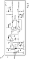
- the device 1 comprises an inductive sensor 5, a capacitor 6, an amplifier 7, a first peak-hold detector 8, a second peak-hold detector 9, an evaluation device 10 and a communication interface 11, as in FIG Fig. 1 . 2 . 5 and 6 shown.
- the inductive sensor 5 in the form of a coil is designed so that due to the changing magnetic flux B in the inductive sensor 5, a voltage signal IS is induced.
- the capacitor 6 is electrically connected to the inductive sensor 5.
- the amplifier 7 is designed in the form of an operational amplifier to amplify the induced voltage signal IS in an output voltage signal AS. In alternative embodiments, the amplifier may be configured to amplify a signal based on the voltage signal into an output voltage signal.
- the first peak-hold detector 8 is designed to generate an upper peak signal OP from the output voltage signal AS. In alternative embodiments, the first peak-hold detector may be configured to generate an upper peak signal from a signal based on the output voltage signal.
- the second peak-hold detector 9 is designed to generate a lower peak signal UP from the output voltage signal AS. In alternative embodiments, the second peak-hold detector may be configured to generate a lower peak signal from the signal based on the output voltage signal.
- the evaluation device 10 is designed to form a difference DI from the generated upper peak signal OP and the generated lower peak signal UP. Furthermore, in the exemplary embodiment shown, the evaluation device 10 in the form of a microcontroller is designed to compare the difference DI formed with an adjustable threshold value ES. In alternative embodiments, the evaluation device may be configured to compare a variable based on the difference formed with an adjustable threshold value. In addition, the evaluation device 10 is designed to determine the on-state On of the drive motor 2, 3 upon reaching or exceeding the threshold value ES. In the exemplary embodiment shown, the communication interface 11 is configured to transmit operating data BD based on the on-state On wirelessly to a terminal 12. In alternative embodiments, the communication interface may be configured to wirelessly send the particular on-state to the terminal.
- the device 1 for detecting an off state Off of the drive motor 2, 3 of the tool 4 is formed.
- the off state Off of the drive motor 2, 3 no changing magnetic flux is effected and in the inductive sensor 5 no voltage signal is induced.
- the evaluation device 10 is configured to determine the off-state Off of the drive motor 2, 3 when it falls below the threshold value ES.
- the communication interface 11 is configured to wirelessly transmit the operation data BD based on the off-state Off to the terminal 12.
- a flow direction with respect to the inductive sensor 5 is to be considered for detecting the changing magnetic flux.
- the inductive sensor 5 may comprise a plurality of individual partial coils, which may be oriented differently from each other. Furthermore, a defined positioning of the inductive sensor 5 on the tool 4 or a defined orientation of the inductive sensor 5 with respect to the tool 4 can be selected.
- the changing magnetic flux B is caused by an ignition pulse ZI of the internal combustion engine 2.
- the inductive sensor 5 and the capacitor 6 form at least part of a resonant circuit 13.
- the device 1 has protective diodes SD with parasitic capacitances CSD.
- the inductive sensor 5, the capacitor 6 and the protective diodes SD completely form the resonant circuit 13.
- the inductive sensor 5 has an inductance L5 of 15 mH.
- the inductive sensor may have an inductance of at least 10 ⁇ H and / or a maximum of 1000 mH.
- the capacitor 6 has an electrical capacitance C6 of at least 1 pF and / or of at most 1 ⁇ F.
- the electrical oscillating circuit 13 has a resonant frequency fq13 of at least 50 Hz and / or a maximum of 5 MHz.
- the amplifier 7 has a gain bandwidth product VBP7 of at least 100 kHz and / or a maximum of 5 MHz.
- the capacitor 6 tunes the resonant circuit 13 and thus significantly improves the difference DI at high frequencies fq from 100 kHz, as in Fig. 3 for excitation of the device 1 with a single pulse for different frequencies fq with and without capacitor 6 shown.
- the resonant circuit 13 or the capacitor 6 makes it possible for the induced voltage signal IS at the amplifier 7 to be artificially slowed down or slowed down as a result of oscillations occurring in the case of a magnetic flux B that changes relatively rapidly over time, in particular the relatively short and / or relatively steep ignition pulse ZI is dampened.
- the output voltage signal AS spends more time over threshold values of the peak hold detectors 8, 9 for charging or discharging sample capacitors C8, C9 of the peak hold detectors 8, 9.
- the difference DI is relatively large.
- the amplifier 7 amplifies the induced voltage signal IS by a factor of 100.
- the device 1 has an electrical energy store 14, in particular a battery in the form of a button cell.
- the electrical energy store 14 is designed to provide the inductive sensor 5, the capacitor 6, the amplifier 7, the first peak-hold detector 8, the second peak-hold detector 9, the evaluation device 10 and / or the communication interface 11 with electrical To supply energy, in particular with a voltage, for example, of 3 V.
- the device 1 has at least one electrical resistance R1, R2.
- the at least one electrical resistance R1, R2 is electrically connected to the inductive sensor 5 and an input 7E of the amplifier 7 such that the input 7E is at a higher voltage level than 0V when no changing magnetic flux through the inductive sensor 5 is detected is, for example, to 1.5 V, especially when supplied with electrical energy or voltage.
- the device has a first electrical resistance R1 and a second electrical resistance R2.
- the capacitor 6 is electrically connected to the inductive sensor 5 and the input 7E of the amplifier 7 such that the capacitor 6 supports the input 7E upon detection of the changing magnetic flux B by the inductive sensor 5 to a positive voltage, especially in supply with electrical energy or voltage.
- the device 1 has a reference voltage of 0 V or ground GND.
- the device 1 or its evaluation device 10 has a pin or a port P1.0.
- the device 1 or its evaluation device 10 is designed to configure the pin P1.0 either as an output or into a power-saving state PS and / or either to low or 0 V or GND or to high or the voltage of the electrical energy store 14, for example 3 V, to put.
- the inductive sensor 5 may be at a voltage higher than 0V.
- the capacitor 6 and the first electrical resistance R1 between ground GND and the inductive sensor 5 are connected in parallel.
- the evaluation device has an analog-to-digital converter ADC.
- the analog-to-digital converter ADC is designed to form the difference DI from the upper peak signal OP and the lower peak signal UP.
- the analog-to-digital converter ADC has a first pin or a first port ADC0. Furthermore, the analog-to-digital converter ADC has a second pin or a second port ADC1.
- the device 1 or its evaluation device 10 or its analog-to-digital converter ADC is designed to connect the first pin ADC0 and / or the second pin ADC1, in particular in each case, either to configure it as an output or as an input or into an energy-saving state PS and / or to set it to either low or 0 V or GND or to high or the voltage of the electrical energy store 14, for example 3V.
- the first pin ADC0 is electrically connected to the first peak-hold detector 8.
- the second pin ADC1 is electrically connected to the second peak-hold detector 9.
- first peak-hold detector 8 is electrically connected to the amplifier 7 and the second peak-hold detector 9 is electrically connected to the amplifier 7.
- the first peak-hold detector 8 has a first sample capacitor C8.
- the second peak-hold detector 9 has a second sample capacitor C9.
- the device 1 is designed to periodically detect the inductive sensor 5, the capacitor 6, the amplifier 7, the first peak-hold detector 8 and / or the second peak-hold detector 9 during a wake time duration twake with electrical energy Voltage, in particular from the electric energy storage 14, to supply and during a sleep period tsleep not to provide electrical energy.
- the wake duration twake is 40 ms. In alternative embodiments, the wake period may be a minimum of 10 ms and / or a maximum of 1000 ms.
- the sleep time tsleep is 960 ms.
- the sleep time may be a minimum of 500 ms and / or a maximum of 600 s.
- the device 1 or its evaluation device 10 or its analog-to-digital converter ADC is adapted to reset the first peak-hold detector 8 and the second peak-hold detector 9, in particular in an initial state, in particular after the time of forming the Difference DI.
- the pin P1.0 is first configured as output and set to low for detection, as in Fig. 4 shown.
- the first pin ADC0 and the second pin ADC1 are configured, in particular in each case, as an output.
- the first pin ADC0 is set to low.
- the second pin ADC1 is set to low.
- the first pin ADC0 and the second pin ADC1, in particular respectively, are configured as an input.
- a detection time window is opened.
- the pin P1.0 is set to high, especially for the waking time twake.
- the inductive sensor 5, the capacitor 6, the amplifier 7, the first peak-hold detector 8 and / or the second peak-hold detector 9 are supplied with electrical energy.
- the analog-to-digital converter ADC forms the difference DI from the upper peak signal OP and the lower peak signal UP.
- the first pin ADC0 is configured as output and set to low.
- the pin P1.0 is set to low.
- the second pin ADC0 is configured as output and set to low.
- the first pin ADC0 and the second pin ADC1, in particular respectively, are configured in the power-saving state PS.
- Pin P1.0 is configured to the energy-saving state PS.
- the inductive sensor 5, the capacitor 6, the amplifier 7, the first peak-hold detector 8 and / or the second peak-hold detector 9 are not supplied with electrical energy.
- the device 1 or its evaluation device 10 or its analog-to-digital converter ADC resets the first peak-hold detector 8 and the second peak-hold detector 9.
- the evaluation device 10 Upon reaching or exceeding the threshold value ES by the difference DI, the evaluation device 10 determines that the state of the drive motor 2, 3 is on. When the threshold value ES is undershot by the difference, the evaluation device 10 determines that the state of the drive motor 2, 3 is off.
- the evaluation device 10 is designed to determine the operating data BD, in particular in the form of operating hours, in particular during which the drive motor is on or active.
- the communication interface 11 is electrically connected to the evaluation device 10.
- the communication interface 11 is configured to receive a setting of the threshold value ES wirelessly.
- the communication interface 11 is adapted to transmit the difference DI and / or a signal based on the difference wirelessly to the terminal 12.
- the terminal 12 is to determine the setting of the threshold value ES based on the received difference DI and to transmit the specific setting of the threshold value ES.
- the device 1 has an operating data memory 15.
- the operating data memory 15 is designed to store the operating data BD.
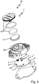
- the device 1 is formed separately from the tool 4, as in Fig. 5 and 6 shown.
- the device 1 has a housing 30.
- the housing 30 is designed to receive the electrical energy store 14.
- the device 1 resilient electrical contact elements 31, 32, in the illustrated embodiment two.
- the resilient electrical contact elements 31, 32 are designed to electrically contact corresponding electrical contacts of the received electrical energy store 14.
- the contact elements 31, 32 led out of the housing 30 to the outside and there electrically connected to corresponding terminals, in particular on a circuit board 40 of the device 1, respectively.
- the circuit board 40 is arranged on an underside of the housing 30.
- the circuit board 40 is mechanically connected to the housing 30.
- the invention provides a device for detecting an on-state of a drive motor of a tool that is well grasped and energy-saving and flexible, and a system having such a device and a tool having a drive motor and / or a terminal ready.
Landscapes
- Engineering & Computer Science (AREA)
- Physics & Mathematics (AREA)
- General Physics & Mathematics (AREA)
- Computer Networks & Wireless Communication (AREA)
- Mechanical Engineering (AREA)
- Signal Processing (AREA)
- Condensed Matter Physics & Semiconductors (AREA)
- Power Engineering (AREA)
- Medical Informatics (AREA)
- Chemical & Material Sciences (AREA)
- Combustion & Propulsion (AREA)
- General Health & Medical Sciences (AREA)
- General Engineering & Computer Science (AREA)
- Computing Systems (AREA)
- Health & Medical Sciences (AREA)
- Arrangements For Transmission Of Measured Signals (AREA)
Abstract
Description
- Die Erfindung betrifft eine Einrichtung zur Erfassung eines Ein-Zustands eines Antriebsmotors eines Werkzeugs und ein System mit einer solchen Einrichtung und einem Werkzeug aufweisend einen Antriebsmotor und/oder einem Endgerät.
- Der Erfindung liegt als Aufgabe die Bereitstellung einer Einrichtung zur Erfassung eines Ein-Zustands eines Antriebsmotors eines Werkzeugs, die gut erfasst und energiesparend und flexibel ist, und eines Systems mit einer solchen Einrichtung und einem Werkzeug aufweisend einen Antriebsmotor und/oder einem Endgerät zugrunde.
- Die Erfindung löst diese Aufgabe durch die Bereitstellung einer Einrichtung mit den Merkmalen des Anspruchs 1 und eines Systems mit den Merkmalen des Anspruchs 13 und/oder des Anspruchs 15. Vorteilhafte Weiterbildungen und/oder Ausgestaltungen der Erfindung sind in den abhängigen Ansprüchen beschrieben.
- Die erfindungsgemäße Einrichtung ist zur, insbesondere automatischen, Erfassung beziehungsweise Detektion eines Ein-Zustands, insbesondere einer, insbesondere von Null verschiedenen, Drehzahl, eines Antriebsmotors eines Werkzeugs ausgebildet. Die Einrichtung ist zur Anordnung an, insbesondere in, dem Werkzeug ausgebildet. Im Ein-Zustand, insbesondere bei der, insbesondere von Null verschiedenen, Drehzahl, des Antriebsmotors wird ein sich, insbesondere zeitlich, ändernder magnetischer Fluss bewirkt, insbesondere nur im Ein-Zustand. Die Einrichtung weist einen, insbesondere elektrischen, induktiven Sensor, einen, insbesondere elektrischen, Kondensator, einen, insbesondere elektrischen, Verstärker, einen, insbesondere elektrischen, ersten Peak-Hold-Detektor, einen, insbesondere elektrischen, zweiten Peak-Hold-Detektor, eine, insbesondere elektrische, Auswerteeinrichtung und eine, insbesondere elektrische, Kommunikationsschnittstelle auf. Der induktive Sensor ist dazu ausgebildet, dass aufgrund des sich ändernden magnetischen Flusses in dem induktiven Sensor ein, insbesondere elektrisches, Spannungssignal induziert wird, insbesondere automatisch. Der Kondensator ist elektrisch mit dem induktiven Sensor verbunden. Der Verstärker ist dazu ausgebildet, das induzierte Spannungssignal oder ein auf dem Spannungssignal basierendes Signal in ein, insbesondere elektrisches, Ausgangsspannungssignal zu verstärken, insbesondere automatisch. Der erste Peak-Hold-Detektor ist dazu ausgebildet, aus dem Ausgangsspannungssignal oder einem auf dem Ausgangsspannungssignal basierenden Signal ein, insbesondere elektrisches, oberes Peaksignal zu erzeugen, insbesondere automatisch. Der zweite Peak-Hold-Detektor ist dazu ausgebildet, aus dem Ausgangsspannungssignal oder dem auf dem Ausgangsspannungssignal basierenden Signal ein, insbesondere elektrisches, unteres Peaksignal zu erzeugen, insbesondere automatisch. Die Auswerteeinrichtung ist dazu ausgebildet, aus dem erzeugten oberen Peaksignal und dem erzeugten unteren Peaksignal eine Differenz zu bilden, die gebildete Differenz, insbesondere einen Wert beziehungsweise einen Betrag der Differenz, oder eine auf der gebildeten Differenz basierende Größe, insbesondere einen Wert beziehungsweise einen Betrag der Größe, mit einem einstellbaren, insbesondere einem benutzereinstellbaren, Schwellwert zu vergleichen, und bei Erreichung oder Überschreitung des Schwellwerts den Ein-Zustand, insbesondere die Drehzahl, des Antriebsmotors zu bestimmen beziehungsweise zu ermitteln, insbesondere automatisch. Die Kommunikationsschnittstelle ist dazu ausgebildet, den bestimmten Ein-Zustand, insbesondere die Drehzahl, und/oder auf dem Ein-Zustand basierende Betriebsdaten drahtlos zu einem Endgerät zu senden beziehungsweise zu übertragen, insbesondere automatisch.
- Die Einrichtung beziehungsweise ihr Kondensator und ihre Peak-Hold-Detektoren ermöglichen eine relativ gute Erfassung des Ein-Zustands, insbesondere der Drehzahl, bei einem relativ niedrigen Energieverbrauch. Im Detail ermöglicht der Kondensator eine Nutzung eines Frequenzganges in Richtung höhere Frequenzen und somit, dass der Verstärker relativ langsam und somit relativ energiesparend und kostengünstig sein kann. Die Peak-Hold-Detektoren ermöglichen, beide Halbwellen des Ausgangsspannungssignals und/oder des auf dem Ausgangsspannungssignal basierenden Signals auswerten zu können. Des Weiteren ermöglicht die Einrichtung beziehungsweise ihre Auswerteeinrichtung beziehungsweise ihr einstellbarer Schwellwert eine relativ große Flexibilität, insbesondere eine Anpassung an das Werkzeug beziehungsweise seinen Antriebsmotor.
- Zusätzlich kann die Einrichtung zur, insbesondere automatischen, Erfassung eines Aus-Zustands, insbesondere einer Drehzahl Null, des Antriebsmotors des Werkzeugs ausgebildet sein. Insbesondere braucht oder kann im Aus-Zustand des Antriebsmotors kein sich ändernder magnetischer Fluss bewirkt werden und im induktiven Sensor braucht oder kann kein Spannungssignal induziert werden. Zusätzlich oder alternativ kann die Auswerteeinrichtung dazu ausgebildet sein, bei Unterschreitung des Schwellwerts den Aus-Zustand des Antriebsmotors zu bestimmen, insbesondere automatisch. Weiter zusätzlich oder alternativ kann die Kommunikationsschnittstelle dazu ausgebildet sein, den bestimmten Aus-Zustand und/oder auf dem Aus-Zustand basierende Betriebsdaten drahtlos zu dem Endgerät zu senden, insbesondere automatisch.
- Das Werkzeug kann einen Elektroantriebsmotor oder einen Verbrennungsantriebsmotor aufweisen beziehungsweise mittels eines Elektromotors oder eines Verbrennungsmotors angetrieben sein. Insbesondere kann der Elektromotor ein Universalmotor, oder ein bürstenbehafteter Gleichstrommotor, oder ein bürstenloser Gleichstrommotor, oder ein Drehstrommotor sein. Zusätzlich oder alternativ kann der sich ändernde magnetische Fluss durch ein Streufeld des Elektroantriebsmotors, einen Zündimpuls des Verbrennungsantriebsmotors, Stromänderungen, sich bewegende Magnete in einem Schwungrad des Werkzeugs, eines Generators, etc. verursacht sein oder werden. Insoweit sei auch auf die einschlägige Fachliteratur verwiesen.
- Die Einrichtung kann zur, insbesondere mechanischen, Kopplung mit beziehungsweise Anbringung beziehungsweise Befestigung an, insbesondere in, dem Werkzeug ausgebildet sein. Insbesondere kann die Einrichtung zur, insbesondere lösbaren, Verbindung mit dem Werkzeug ausgebildet sein, insbesondere durch eine stoffschlüssige Verbindung wie eine Verklebung, eine kraftschlüssige Verbindung wie eine Rast- beziehungsweise Schnappverbindung und/oder ein formschlüssige Verbindung wie eine Verschraubung. Zusätzlich oder alternativ kann die Einrichtung an, insbesondere in, dem Werkzeug angeordnet sein, insbesondere ein Teil des Werkzeugs sein. Alternativ kann die Einrichtung getrennt von dem Werkzeug ausgebildet sein. Dies ermöglicht eine Nachrüstung der Einrichtung an dem Werkzeug. Insbesondere kann die Einrichtung als Gerät bezeichnet werden. Weiter zusätzlich oder alternativ kann die Einrichtung bei Anordnung an dem Werkzeug in direktem Kontakt mit dem Werkzeug sein, insbesondere einem Werkzeuggehäuse beziehungsweise einer Haube des Werkzeugs.
- Der induktive Sensor kann dazu ausgebildet sein, dass, unabhängig davon, ob das Werkzeug mittels eines Elektroantriebsmotors oder eines Verbrennungsantriebsmotors angetrieben sein kann, aufgrund des sich ändernden magnetischen Flusses in dem induktiven Sensor das Spannungssignal induziert werden kann. Somit kann der Ein-Zustand, insbesondere die, insbesondere von Null verschiedene, Drehzahl, für eine Vielzahl von Antriebstechnologien wie kabelgebunden, Akkumulator-basiert, verbrennungsmotorgetrieben mit derselben Einrichtung erfasst werden, insbesondere ohne dass eine leitungsgebundene Verbindung mit dem Werkzeug beziehungsweise mit Komponenten des Werkzeugs erforderlich sein braucht. Zusätzlich oder alternativ kann der induktive Sensor dazu ausgebildet sein, den sich ändernden magnetischen Fluss drahtlos zu erfassen beziehungsweise zu detektieren, insbesondere ohne eine galvanische Verbindung mit dem Werkzeug beziehungsweise Komponenten des Werkzeugs aufzuweisen. Weiter zusätzlich oder alternativ kann der induktive Sensor eine, insbesondere elektrische, Spule, insbesondere in Form einer bedrahteten Spule, einer Induktivität auf einem Chip und/oder einer SMD-Spule, aufweisen oder sein. Weiter zusätzlich oder alternativ kann das Spannungssignal als Selbstinduktionsspannungssignal bezeichnet werden. Insoweit sei auch auf die einschlägige Fachliteratur verwiesen.
- Der induktive Sensor und der Kondensator können in Reihe geschaltet sein, insbesondere in Bezug auf einen Eingang des Verstärkers. Insbesondere können der Kondensator, der induktive Sensor und der Eingang, insbesondere in dieser Reihenfolge, in Reihe geschaltet sein.
- Der Verstärker kann mit dem induktiven Sensor und/oder dem Kondensator elektrisch verbunden sein. Zusätzlich oder alternativ kann der Verstärker einen Operationsverstärker aufweisen oder sein. Insoweit sei auch auf die einschlägige Fachliteratur verwiesen.
- Der erste Peak-Hold-Detektor und/oder der zweite Peak-Hold-Detektor können/kann, insbesondere jeweils, mit dem Verstärker, elektrisch verbunden sein. Zusätzlich oder alternativ können der erste Peak-Hold-Detektor und der zweite Peak-Hold-Detektor verschieden und/oder baugleich sein. Weiter zusätzlich oder alternativ können das obere Peaksignal und das untere Peaksignal verschieden sein. Insoweit sei auch auf die einschlägige Fachliteratur verwiesen.
- Die Auswerteeinrichtung kann mit dem ersten Peak-Hold-Detektor und/oder dem zweiten Peak-Hold-Detektor elektrisch verbunden sein. Zusätzlich oder alternativ kann die Differenzbildung softwareseitig sein. Weiter zusätzlich oder alternativ kann der Schwellwert in mindestens drei, insbesondere in mindestens fünf, insbesondere in mindestens zehn, insbesondere in mindestens zwanzig, insbesondere in mindestens fünfzig, insbesondere in mindestens hundert, verschiedenen Stufen oder kontinuierlich einstellbar sein. Weiter zusätzlich oder alternativ kann der Schwellwert softwareseitig sein. Weiter zusätzlich oder alternativ kann die Auswerteeinrichtung dazu ausgebildet sein, bei Erreichung oder Überschreitung des Schwellwerts zu bestimmen, dass der Zustand des Antriebsmotors Ein sein kann oder ist, insbesondere einen Wert beziehungsweise einen Betrag der, insbesondere von Null verschiedenen, Drehzahl zu bestimmen, und/oder bei Unterschreitung des Schwellwerts zu bestimmen, dass der Zustand des Antriebsmotors Aus sein kann oder ist. Weiter zusätzlich oder alternativ kann die Auswerteeinrichtung dazu ausgebildet sein, die Betriebsdaten, insbesondere in Form von Betriebsstunden beziehungsweise einer Betriebszeitdauer, insbesondere während welcher der Antriebsmotor Ein beziehungsweise aktiv sein kann, zu bestimmen beziehungsweise zu ermitteln. Weiter zusätzlich oder alternativ kann die Auswerteeinrichtung einen Mikrocontroller aufweisen oder sein. Insoweit sei auch auf die einschlägige Fachliteratur verwiesen.
- Zusätzlich kann die Einrichtung einen, insbesondere elektrischen, Betriebsdatenspeicher aufweisen. Der Betriebsdatenspeicher kann dazu ausgebildet sein, den bestimmten Ein-Zustand, insbesondere die, insbesondere von Null verschiedene, Drehzahl, und/oder auf dem Ein-Zustand basierende Betriebsdaten zu speichern, insbesondere automatisch. Insbesondere kann der Betriebsdatenspeicher mit der Auswerteeinrichtung elektrisch verbunden sein. Zusätzlich oder alternativ kann der Betriebsdatenspeicher ein flüchtiger Speicher wie ein RAM (Random Access Memory) und/oder einen nicht-flüchtigen Speicher wie einen EEPROM-Speicher aufweisen oder sein. Insoweit sei auch auf die einschlägige Fachliteratur verwiesen.
- Die Kommunikationsschnittstelle kann mit der Auswerteeinrichtung und/oder dem Betriebsdatenspeicher, soweit vorhanden, elektrisch verbunden sein. Insbesondere kann die Kommunikationsschnittstelle dazu ausgebildet sein, den gespeicherten Ein-Zustand, insbesondere die, insbesondere von Null verschiedene, Drehzahl, und/oder gespeicherte Betriebsdaten drahtlos zu dem Endgerät zu senden, insbesondere automatisch. Zusätzlich oder alternativ kann die Kommunikationsschnittstelle eine WLAN-Schnittstelle und/oder eine Bluetooth-Schnittstelle aufweisen oder sein. Weiter zusätzlich oder alternativ kann die Kommunikationsschnittstelle dazu ausgebildet sein, zu senden, unabhängig davon, ob sich ein Endgerät in Reichweite befindet oder nicht. Es kann ein festes oder ein veränderliches Zeitintervall zum Senden verwendet werden. Insoweit sei auch auf die einschlägige Fachliteratur verwiesen.
- Die Einrichtung kann als elektrische Einrichtung bezeichnet werden. Zusätzlich oder alternativ kann die oben beschriebene Einrichtung mit allen ihren oder einem Teil ihrer Eigenschaften dazu vorgesehen sein, mit dem Werkzeug zur Erfassung des Ein-Zustands, insbesondere der, insbesondere von Null verschiedenen, Drehzahl, des Antriebsmotors des Werkzeugs verwendet werden zu können. In anderen Worten: Verwendung der Einrichtung zur Erfassung des Ein-Zustands, insbesondere der, insbesondere von Null verschiedenen, Drehzahl, des Antriebsmotors des Werkzeugs.
- Das Endgerät kann beispielsweise basierend auf dem empfangenen Ein-Zustand, insbesondere der, insbesondere von Null verschiedenen, Drehzahl, und/oder den empfangenen Betriebsdaten Auswertungen vornehmen und diese beispielsweise einem Benutzer optisch aufbereitet darstellen.
- In einer Weitebildung der Erfindung ist der Antriebsmotor ein Verbrennungsantriebsmotor. Der sich ändernde magnetische Fluss ist oder wird durch einen Zündimpuls des Verbrennungsantriebsmotors verursacht. Die Einrichtung beziehungsweise ihr Kondensator ermöglicht eine Erfassung des Zündimpulses. Insbesondere kann der Zündimpuls zeitlich relativ kurz und/oder relativ steil sein. Zusätzlich oder alternativ kann der Zündimpuls durch eine Zündkerze oder ein Zündkabel verursacht sein oder werden.
- In einer Weiterbildung der Erfindung bilden der induktive Sensor und der Kondensator mindestens einen Teil eines, insbesondere elektrischen, Schwingkreises, insbesondere vollständig einen, insbesondere elektrischen, Schwingkreis. Dies ermöglicht, dass bei einem sich zeitlich relativ schnell ändernden magnetischen Fluss, insbesondere dem zeitlich relativ kurzen und/oder relativ steilen Zündimpuls, das induzierte Spannungssignal oder das auf dem Spannungssignal basierende Signal beziehungsweise ein Eingangssignal am Verstärker durch entstehende Oszillationen beziehungsweise Schwingungen künstlich verlangsamt beziehungsweise langsamer gedämpft werden kann oder wird. Somit kann das Ausgangsspannungssignal mehr Zeit über Schwellwerten der Peak-Hold-Detektoren zum Laden beziehungsweise Entladen von Samplekondensatoren der Peak-Hold-Detektoren verbringen. Somit kann die Differenz relativ groß sein. Somit kann der sich zeitlich relativ schnell ändernde magnetische Fluss, insbesondere der Zündimpuls, erfasst oder detektiert werden, der gemäß einem Verstärkungs-Bandbreite-Produkt des Verstärkers ohne Kondensator beziehungsweise Schwingkreis gar nicht messbar sein dürfte. Insbesondere kann der Verstärker mit dem Schwingkreis elektrisch verbunden sein.
- In einer Weiterbildung der Erfindung weist der induktive Sensor eine, insbesondere elektrische, Induktivität von minimal 10 Mikrohenry (µH) und/oder von maximal 1000 Millihenry (mH) auf, insbesondere von 15 mH. Zusätzlich oder alternativ weist der Kondensator eine elektrische Kapazität von minimal 1 Pikofarad (pF) und/oder von maximal 1 Mikrofarad (µF) auf. Zusätzlich oder alternativ weist der elektrische Schwingkreis, soweit vorhanden, eine Resonanzfrequenz von minimal 50 Hertz (Hz) und/oder von maximal 5 Megahertz (MHz) auf. Zusätzlich oder alternativ weist der Verstärker ein Verstärkungs-Bandbreite-Produkt von minimal 100 Kilohertz (kHz) und/oder von maximal 5 Megahertz (MHz) auf. Insbesondere kann die Resonanzfrequenz von der Induktivität und der Kapazität abhängen.
- In einer Weiterbildung der Erfindung weist die Einrichtung einen elektrischen Energiespeicher, insbesondere eine Batterie, auf. Der elektrischer Energiespeicher ist dazu ausgebildet, den induktiven Sensor, den Kondensator, den Verstärker, den ersten Peak-Hold-Detektor, den zweiten Peak-Hold-Detektor, die Auswerteeinrichtung und/oder die Kommunikationsschnittstelle mit elektrischer Energie beziehungsweise Spannung zu versorgen, insbesondere automatisch. Der elektrische Energiespeicher ermöglicht, dass die Einrichtung ohne äußere Energieversorgung sein kann. Insbesondere kann die Batterie eine Knopfzelle, insbesondere eine CR 2032-Knopfzelle oder CR 2450-Knopfzelle, und/oder eine Lithium-Ionen-Batterie sein.
- In einer Weiterbildung der Erfindung weist die Einrichtung mindestens einen elektrischen Widerstand auf. Der mindestens eine elektrische Widerstand ist mit dem induktiven Sensor und/oder einem, insbesondere dem, Eingang des Verstärkers derart elektrisch verbunden, dass der Eingang bei Nicht-Erfassung eines sich ändernden magnetischen Flusses beziehungsweise einer Erfassung keines sich ändernden magnetischen Flusses durch den induktiven Sensor beziehungsweise in Ruhe auf einem höheren Spannungspegel als 0 (Null) Volt (V) liegt, insbesondere bei Versorgung mit elektrischer Energie beziehungsweise Spannung, insbesondere automatisch. In anderen Worten: der elektrische Widerstand kann dazu ausgebildet sein, ein Spannungsoffset des induktiven Sensors beziehungsweise seines Spannungssignals zu generieren beziehungsweise zu erzeugen. Dies ermöglicht, dass sowohl eine positive Halbwelle als auch eine negative Halbwelle des induzierten Spannungssignals oder des auf dem Spannungssignal basierenden Signals genutzt werden können. Somit kann das Ausgangsspannungssignal sowohl eine positive Halbwelle als auch eine negative Halbwelle beziehungsweise die Halbwellen aufweisen. Insbesondere können der mindestens eine elektrische Widerstand und der induktive Sensor in Reihe geschaltet sein. Zusätzlich oder alternativ kann die Einrichtung zwei elektrische Widerstände aufweisen. Weiter zusätzlich oder alternativ können die 0 V als Bezugsspannung oder Ground bezeichnet werden.
- In einer Ausgestaltung der Erfindung ist der Kondensator mit dem induktiven Sensor und/oder dem Eingang des Verstärkers derart elektrisch verbunden, dass der Kondensator den Eingang bei Erfassung des sich ändernden magnetischen Flusses durch den induktiven Sensor auf eine positive Spannung stützt, insbesondere bei Versorgung mit elektrischer Energie beziehungsweise Spannung, insbesondere automatisch. Dies ermöglicht, dass der Verstärker eine relativ kurze Erholungszeit haben kann und somit bei hohen Frequenzen ein relativ gutes Reaktionsvermögen aufweisen kann beziehungsweise performant sein kann.
- In einer Weiterbildung der Erfindung weist die Auswerteeinrichtung einen, insbesondere elektrischen, Analog-Digital-Umsetzer auf. Der Analog-Digital-Umsetzer ist dazu ausgebildet, aus dem oberen Peaksignal und dem unteren Peaksignal die Differenz zu bilden, insbesondere zu digitalisieren, insbesondere automatisch. Insbesondere können/kann das obere Peaksignal und/oder das untere Peaksignal, insbesondere jeweils, analog sein. Zusätzlich oder alternativ kann die Differenz digital sein. Weiter zusätzlich oder alternativ kann der Analog-Digital-Umsetzer mit dem ersten Peak-Hold-Detektor und/oder dem zweiten Peak-Hold-Detektor elektrisch verbunden sein.
- In einer Weiterbildung der Erfindung ist die Kommunikationsschnittstelle dazu ausgebildet, eine Einstellung des Schwellwerts drahtlos zu empfangen, insbesondere von einem, insbesondere, dem Endgerät, insbesondere automatisch. Dies ermöglicht eine relativ einfache und somit benutzerfreundliche Einstellung des Schwellwerts. Insbesondere kann die Kommunikationsschnittstelle dazu ausgebildet sein, die Differenz und/oder ein auf der Differenz basierendes Signal drahtlos zu einem, insbesondere dem, Endgerät zu senden. Das Endgerät kann dazu ausgebildet sein, basierend auf der empfangenen Differenz die Einstellung des Schwellwerts zu bestimmen beziehungsweise zu ermitteln und die bestimmte Einstellung des Schwellwerts zu senden. Zusätzlich oder alternativ kann die Kommunikationsschnittstelle dazu ausgebildet sein, die empfangene Einstellung des Schwellwerts an die Auswerteeinrichtung weiterzuleiten, insbesondere so dass die Auswerteeinrichtung die Einstellung des Schwellwerts als, insbesondere neuen, Schwellwert übernehmen kann. Weiter zusätzlich oder alternativ kann die Kommunikationsschnittstelle als bidirektionale Kommunikationsschnittstelle bezeichnet werden.
- In einer Weiterbildung der Erfindung ist die Einrichtung dazu ausgebildet, den induktiven Sensor, den Kondensator, den Verstärker, den ersten Peak-Hold-Detektor und/oder den zweiten Peak-Hold-Detektor periodisch beziehungsweise zyklisch während einer Wachzeitdauer mit elektrischer Energie beziehungsweise Spannung, insbesondere von dem elektrischen Energiespeicher, soweit vorhanden, zu versorgen beziehungsweise zu aktivieren und während einer Schlafzeitdauer nicht mit elektrischer Energie zu versorgen beziehungsweise zu deaktivieren, insbesondere automatisch. Dies ermöglicht einen relativ niedrigen Energieverbrauch und somit eine relativ lange Laufzeit des elektrischen Energiespeichers, soweit vorhanden. Insbesondere kann die Einrichtung dazu ausgebildet sein, die Auswerteeinrichtung und/oder die Kommunikationsschnittstelle nicht während der Wachzeitdauer, sondern zeitlich danach mit elektrischer Energie zu versorgen beziehungsweise zu aktivieren, insbesondere periodisch. Insbesondere kann dann die Auswerteeinrichtung das obere Peaksignal, das von dem ersten Peak-Hold-Detektor gehalten werden kann oder wird, und das untere Peaksignal, das von dem zweiten Peak-Hold-Detektor gehalten werden kann oder wird, analysieren beziehungsweise auswerten, insbesondere die Differenz bilden, vergleichen und den Zustand, insbesondere die Drehzahl, bestimmen. Die Einrichtung dazu ausgebildet sein, die Auswerteeinrichtung und/oder die Kommunikationsschnittstelle zeitlich danach nicht mit elektrischer Energie zu versorgen beziehungsweise zu deaktivieren.
- In einer Ausgestaltung der Erfindung ist die Wachzeitdauer minimal 10 Millisekunden (ms), insbesondere minimal 30 ms, und/oder maximal 1000 ms, insbesondere maximal 100 ms, insbesondere 40 ms. Zusätzlich oder alternativ ist die Schlafzeitdauer minimal 500 ms, insbesondere minimal 900 ms, und/oder maximal 600 Sekunden (s), insbesondere maximal 2 s, insbesondere 960 ms. Die derart dimensionierte Wachzeitdauer ermöglicht, mindestens einen Zündimpuls zu erfassen beziehungsweise zu detektieren.
- In einer Weiterbildung der Erfindung ist die Einrichtung, insbesondere ihre Auswerteeinrichtung, dazu ausgebildet, den ersten Peak-Hold-Detektor und den zweiten Peak-Hold-Detektor zurückzusetzen, insbesondere in einen Anfangszustand, insbesondere zeitlich nach dem Bilden der Differenz, insbesondere automatisch. Dies ermöglicht den Ein-Zustand oder den Aus-Zustand, insbesondere die Drehzahl, des Antriebsmotors des Werkzeugs erneut beziehungsweise wiederholt beziehungsweise periodisch zu erfassen.
- Das erfindungsgemäße System weist eine oben beschriebene Einrichtung und ein Werkzeug auf. Das Werkzeug weist einen Antriebsmotor auf. Insbesondere können/kann das Werkzeug und/oder sein Antriebsmotor teilweise oder ganz wie oben beschrieben ausgebildet sein.
- In einer Weiterbildung der Erfindung ist das Werkzeug ein handgeführtes, insbesondere handgetragenes oder bodengeführtes, Werkzeug. Insbesondere handgeführtes, insbesondere handgetragenes, Werkzeug kann bedeuten, dass das Werkzeug eine Masse von maximal 50 Kilogramm (kg), insbesondere von maximal 20 kg, insbesondere von maximal 10 kg, aufweisen kann. Zusätzlich oder alternativ kann das Werkzeug ein Garten- und/oder Forstbearbeitungswerkzeug oder ein Bodenbearbeitungswerkzeug sein.
- Insbesondere kann das Werkzeug eine Säge, oder ein Hoch-Entaster, oder eine Heckenschere, oder ein Heckenschneider, oder ein Laubbläser, oder ein Laubsauger, oder eine Kehrwalze, oder eine Kehrbürste, oder ein Rasenmäher, oder ein Freischneider, oder ein Vertikutierer, oder ein Trennschleifer, oder eine Motorhacke, oder ein Hochdruckreiniger, oder ein Spritzbeziehungsweise Sprühgerät, oder ein Bohrgerät sein.
- Zusätzlich oder alternativ zu dem Werkzeug kann das erfindungsgemäße System ein Endgerät aufweisen. Insbesondere kann das Endgerät teilweise oder ganz wie oben beschrieben ausgebildet sein. Zusätzlich oder alternativ kann das Endgerät eine beliebige datenverarbeitende Einrichtung sein, die eine geeignete drahtlose Schnittstelle aufweisen kann, die zur drahtlosen Kommunikation mit der Kommunikationsschnittstelle der Einrichtung zur Erfassung des Ein-Zustands, insbesondere der, insbesondere von Null verschiedenen, Drehzahl, des Antriebsmotors ausgebildet sein kann. Weiter zusätzlich oder alternativ kann das Endgerät ein Gateway bilden beziehungsweise sein, das den empfangenen Ein-Zustand, insbesondere die, insbesondere von Null verschiedene, Drehzahl, oder die empfangenen Betriebsdaten an einen Server weiterleiten kann wie an einen sogenannten Cloud-Speicher, der den Ein-Zustand, insbesondere die, insbesondere von Null verschiedene, Drehzahl, oder die Betriebsdaten speichern kann. Der beziehungsweise die im Cloud-Speicher gespeicherte Ein-Zustand, insbesondere die, insbesondere von Null verschiedene, Drehzahl, oder gespeicherten Betriebsdaten können dann mittels eines geeigneten Tools wie eines Web-Browsers betrachtet und ausgewertet werden. Weiter zusätzlich oder alternativ kann das Endgerät ein mobiles Endgerät wie ein Laptop, ein Tablet oder ein Smartphone sein. Insbesondere mobil kann als portabel oder handgeführt, insbesondere handgetragen, bezeichnet werden.
- Weitere Vorteile und Aspekte der Erfindung ergeben sich aus den Ansprüchen und aus der nachfolgenden Beschreibung von bevorzugten Ausführungsbeispielen der Erfindung, die nachfolgend anhand der Figuren erläutert sind. Dabei zeigen:
- Fig. 1
- ein schematisches Blockschaltbild eines erfindungsgemäßen Systems mit einer erfindungsgemäßen Einrichtung zur Erfassung eines Ein-Zustands eines Antriebsmotors eines Werkzeugs, dem Werkzeug und einem Endgerät,
- Fig. 2
- ein detailliertes Blockschaltbild eines Ausschnitts der Einrichtung der
Fig. 1 , - Fig. 3
- einen Graph einer Differenz der Einrichtung der
Fig. 1 mit einem Kondensator und ohne Kondensator über einer Frequenz eines sich ändernden magnetischen Flusses, - Fig. 4
- ein zeitliches Ablaufdiagramm zur Erfassung mittels der Einrichtung der
Fig. 1 , - Fig. 5
- eine schematische Explosionsansicht der Einrichtung der
Fig. 1 , - Fig. 6
- eine schematische Längsschnittansicht der Einrichtung der
Fig. 1 , und - Fig. 7
- eine schematische Perspektivansicht eines Ausschnitts des Werkzeugs der
Fig. 1 . -
Fig. 1 ,2 und5 bis 7 zeigen ein erfindungsgemäßes System 50. Das System 50 weist eine Einrichtung 1, ein Werkzeug 4 und ein Endgerät 12 auf. - Im Detail weist das Werkzeug 4 einen Antriebsmotor 2, 3 auf, insbesondere einen Elektroantriebsmotor 3 oder einen Verbrennungsantriebsmotor 2, wie in
Fig. 1 gezeigt. - Des Weiteren ist das Werkzeug 4 ein handgeführtes Werkzeug. Im gezeigten Ausführungsbeispiel ist das handgeführte Werkzeug 4 ein handgetragenes Werkzeug. In alternativen Ausführungsbeispielen kann das handgeführte Werkzeug ein bodengeführtes Werkzeug sein.
- Im Detail ist das Werkzeug 4 eine Säge, wie in
Fig. 7 gezeigt. Die Säge 4 weist eine Sägekette 20 auf, wobei insbesondere der Elektroantriebsmotor 3 oder der Verbrennungsantriebsmotor 2 zum Antrieb der Sägekette 20 ausgebildet ist. In alternativen Ausführungsbeispielen kann das Werkzeug ein Hoch-Entaster, oder eine Heckenschere, oder ein Heckenschneider, oder ein Laubbläser, oder ein Laubsauger, oder eine Kehrwalze, oder eine Kehrbürste, oder ein Rasenmäher, oder ein Freischneider, oder ein Vertikutierer, oder ein Trennschleifer, oder eine Motorhacke, oder ein Hochdruckreiniger, oder ein Spritz- beziehungsweise Sprühgerät, oder ein Bohrgerät sein. - Die erfindungsgemäße Einrichtung 1 ist zur Erfassung eines Ein-Zustands On des Antriebsmotors 2, 3 des Werkzeugs 4 ausgebildet. Des Weiteren ist die Einrichtung 1 zur Anordnung an dem Werkzeug 4 ausgebildet beziehungsweise im gezeigten Ausführungsbeispiel an dem Werkzeug 4 angeordnet. Im Ein-Zustand On des Antriebsmotors 2, 3 wird ein sich ändernder magnetischer Fluss B bewirkt. Außerdem weist die Einrichtung 1 einen induktiven Sensor 5, einen Kondensator 6, einen Verstärker 7, einen ersten Peak-Hold-Detektor 8, einen zweiten Peak-Hold-Detektor 9, eine Auswerteeinrichtung 10 und eine Kommunikationsschnittstelle 11 auf, wie in
Fig. 1 ,2 ,5 und6 gezeigt. Der induktive Sensor 5 in Form einer Spule ist dazu ausgebildet, dass aufgrund des sich ändernden magnetischen Flusses B in dem induktiven Sensor 5 ein Spannungssignal IS induziert wird. Der Kondensator 6 ist elektrisch mit dem induktiven Sensor 5 verbunden. Im gezeigten Ausführungsbeispiel ist der Verstärker 7 in Form eines Operationsverstärkers dazu ausgebildet, das induzierte Spannungssignal IS in ein Ausgangsspannungssignal AS zu verstärken. In alternativen Ausführungsbeispielen kann der Verstärker dazu ausgebildet sein, ein auf dem Spannungssignal basierendes Signal in ein Ausgangsspannungssignal zu verstärken. Im gezeigten Ausführungsbeispiel ist der erste Peak-Hold-Detektor 8 dazu ausgebildet, aus dem Ausgangsspannungssignal AS ein oberes Peaksignal OP zu erzeugen. In alternativen Ausführungsbeispielen kann der erste Peak-Hold-Detektor dazu ausgebildet sein, aus einem auf dem Ausgangsspannungssignal basierenden Signal ein oberes Peaksignal zu erzeugen. Im gezeigten Ausführungsbeispiel ist der zweite Peak-Hold-Detektor 9 dazu ausgebildet, aus dem Ausgangsspannungssignal AS ein unteres Peaksignal UP zu erzeugen. In alternativen Ausführungsbeispielen kann der zweite Peak-Hold-Detektor dazu ausgebildet sein, aus dem auf dem Ausgangsspannungssignal basierenden Signal ein unteres Peaksignal zu erzeugen. Die Auswerteeinrichtung 10 ist dazu ausgebildet, aus dem erzeugten oberen Peaksignal OP und dem erzeugten unteren Peaksignal UP eine Differenz DI zu bilden. Des Weiteren ist im gezeigten Ausführungsbeispiel die Auswerteeinrichtung 10 in Form eines Mikrocontrollers dazu ausgebildet, die gebildete Differenz DI mit einem einstellbaren Schwellwert ES zu vergleichen. In alternativen Ausführungsbeispielen kann die Auswerteeinrichtung dazu ausgebildet sein, eine auf der gebildeten Differenz basierende Größe mit einem einstellbaren Schwellwert zu vergleichen. Außerdem ist die Auswerteeinrichtung 10 dazu ausgebildet, bei Erreichung oder Überschreitung des Schwellwerts ES den Ein-Zustand On des Antriebsmotors 2, 3 zu bestimmen. Im gezeigten Ausführungsbeispiel ist die Kommunikationsschnittstelle 11 dazu ausgebildet, auf dem Ein-Zustand On basierende Betriebsdaten BD drahtlos zu einem Endgerät 12 zu senden. In alternativen Ausführungsbeispielen kann die Kommunikationsschnittstelle dazu ausgebildet sein, den bestimmten Ein-Zustand drahtlos zu dem Endgerät zu senden. - Zusätzlich ist die Einrichtung 1 zur Erfassung eines Aus-Zustands Off des Antriebsmotors 2, 3 des Werkzeugs 4 ausgebildet. Im Detail wird im Aus-Zustand Off des Antriebsmotors 2, 3 kein sich ändernder magnetischer Fluss bewirkt und im induktiven Sensor 5 wird kein Spannungssignal induziert. Die Auswerteeinrichtung 10 ist dazu ausgebildet, bei Unterschreitung des Schwellwerts ES den Aus-Zustand Off des Antriebsmotors 2, 3 zu bestimmen. Die Kommunikationsschnittstelle 11 ist dazu ausgebildet, die auf dem Aus-Zustand Off basierende Betriebsdaten BD drahtlos zu dem Endgerät 12 zu senden.
- Insbesondere ist zur Erfassung des sich ändernden magnetischen Flusses eine Flussrichtung in Bezug auf den induktiven Sensor 5 zu berücksichtigen. Der induktive Sensor 5 kann mehrere einzelne Teilspulen aufweisen, die zueinander verschieden ausgerichtet sein können. Weiter kann eine definierte Positionierung des induktiven Sensors 5 an dem Werkzeug 4 beziehungsweise eine definierte Ausrichtung des induktiven Sensors 5 in Bezug auf das Werkzeug 4 gewählt werden.
- Im Detail ist der sich ändernde magnetische Fluss B durch einen Zündimpuls ZI des Verbrennungsantriebsmotors 2 verursacht.
- Weiter bilden der induktive Sensor 5 und der Kondensator 6 mindestens einen Teil eines Schwingkreises 13.
- Im Detail weist die Einrichtung 1 Schutzdioden SD mit parasitären Kapazitäten CSD auf. Der induktive Sensor 5, der Kondensator 6 und die Schutzdioden SD bilden vollständig den Schwingkreis 13.
- Im gezeigten Ausführungsbeispiel weist der induktive Sensor 5 eine Induktivität L5 von 15 mH auf. In alternativen Ausführungsbeispielen kann der induktive Sensor eine Induktivität von minimal 10 µH und/oder von maximal 1000 mH aufweisen.
- Des Weiteren weist im gezeigten Ausführungsbeispiel der Kondensator 6 eine elektrische Kapazität C6 von minimal 1 pF und/oder von maximal 1 µF auf.
- Außerdem weist im gezeigten Ausführungsbeispiel der elektrische Schwingkreis 13 eine Resonanzfrequenz fq13 von minimal 50 Hz und/oder von maximal 5 MHz auf.
- Weiter weist im gezeigten Ausführungsbeispiel der Verstärker 7 ein Verstärkungs-Bandbreite-Produkt VBP7 von minimal 100 kHz und/oder von maximal 5 MHz auf.
- Der Kondensator 6 stimmt den Schwingkreis 13 ab und verbessert somit die Differenz DI bei hohen Frequenzen fq ab 100 kHz deutlich, wie in
Fig. 3 für eine Anregung der Einrichtung 1 mit einem Einzelpuls für verschiedene Frequenzen fq mit und ohne Kondensator 6 gezeigt. - Im Detail ermöglicht der Schwingkreis 13 beziehungsweise der Kondensator 6, dass bei einem sich zeitlich relativ schnell ändernden magnetischen Fluss B, insbesondere dem zeitlich relativ kurzen und/oder relativ steilen Zündimpuls ZI, das induzierte Spannungssignal IS am Verstärker 7 durch entstehende Oszillationen künstlich verlangsamt beziehungsweise langsamer gedämpft wird. Somit verbringt das Ausgangsspannungssignal AS mehr Zeit über Schwellwerten der Peak-Hold-Detektoren 8, 9 zum Laden beziehungsweise Entladen von Samplekondensatoren C8, C9 der Peak-Hold-Detektoren 8, 9. Somit ist die Differenz DI relativ groß.
- Des Weiteren verstärkt im gezeigten Ausführungsbeispiel der Verstärker 7 das induzierte Spannungssignal IS um einen Faktor 100.
- Zusätzlich weist die Einrichtung 1 einen elektrischen Energiespeicher 14, insbesondere eine Batterie in Form einer Knopfzelle, auf. Der elektrischer Energiespeicher 14 ist dazu ausgebildet, den induktiven Sensor 5, den Kondensator 6, den Verstärker 7, den ersten Peak-Hold-Detektor 8, den zweiten Peak-Hold-Detektor 9, die Auswerteeinrichtung 10 und/oder die Kommunikationsschnittstelle 11 mit elektrischer Energie zu versorgen, insbesondere mit einer Spannung beispielsweise von 3 V.
- Weiter zusätzlich weist die Einrichtung 1 mindestens einen elektrischen Widerstand R1, R2 auf. Der mindestens eine elektrische Widerstand R1, R2 ist mit dem induktiven Sensor 5 und einem Eingang 7E des Verstärkers 7 derart elektrisch verbunden, dass der Eingang 7E bei Nicht-Erfassung eines sich ändernden magnetischen Flusses durch den induktiven Sensor 5 auf einem höheren Spannungspegel als 0 V liegt, beispielsweise auf 1,5 V, insbesondere bei Versorgung mit elektrischer Energie beziehungsweise Spannung.
- Im gezeigten Ausführungsbeispiel weist die Einrichtung einen ersten elektrischen Widerstand R1 und einen zweiten elektrischen Widerstand R2 auf.
- Zudem ist der Kondensator 6 mit dem induktiven Sensor 5 und dem Eingang 7E des Verstärkers 7 derart elektrisch verbunden, dass der Kondensator 6 den Eingang 7E bei Erfassung des sich ändernden magnetischen Flusses B durch den induktiven Sensor 5 auf eine positive Spannung stützt, insbesondere bei Versorgung mit elektrischer Energie beziehungsweise Spannung.
- Im Detail weist die Einrichtung 1 eine Bezugsspannung von 0 V beziehungsweise Ground GND auf.
- Ground GND, der Kondensator 6, der induktive Sensor 5 und der Eingang 7E des Verstärkers 7 sind in dieser Reihenfolge in Reihe geschaltet.
- Des Weiteren weist die Einrichtung 1 beziehungsweise ihre Auswerteeinrichtung 10 einen Pin beziehungsweise einen Port P1.0 auf. Die Einrichtung 1 beziehungsweise ihre Auswerteeinrichtung 10 ist dazu ausgebildet, den Pin P1.0 entweder als Ausgang oder in einen Energiesparzustand PS zu konfigurieren und/oder entweder auf Low beziehungsweise 0 V beziehungsweise GND oder auf High beziehungsweise die Spannung des elektrischen Energiespeichers 14, beispielsweise 3 V, zu setzen.
- Ground GND, der erste elektrische Widerstand R1, der induktive Sensor 5, der zweite elektrische Widerstand R2 und der Pin P1.0 sind in dieser Reihenfolge in Reihe geschaltet.
- Somit kann der induktive Sensor 5 auf einem höheren Spannungspergel als 0 V liegen.
- Im Detail sind der Kondensator 6 und der erste elektrische Widerstand R1 zwischen Ground GND und dem induktiven Sensor 5 parallel geschaltet.
- Außerdem weist die Auswerteeinrichtung einen Analog-Digital-Umsetzer ADC auf. Der Analog-Digital-Umsetzer ADC ist dazu ausgebildet, aus dem oberen Peaksignal OP und dem unteren Peaksignal UP die Differenz DI zu bilden.
- Im Detail weist der Analog-Digital-Umsetzer ADC einen ersten Pin beziehungsweise einen ersten Port ADC0 auf. Weiter weist der Analog-Digital-Umsetzer ADC einen zweiten Pin beziehungsweise einen zweiten Port ADC1 auf. Die Einrichtung 1 beziehungsweise ihre Auswerteeinrichtung 10 beziehungsweise ihr Analog-Digital-Umsetzer ADC ist dazu ausgebildet, den ersten Pin ADC0 und/oder den zweiten Pin ADC1, insbesondere jeweils, entweder als Ausgang oder als Eingang oder in einen Energiesparzustand PS zu konfigurieren und/oder entweder auf Low beziehungsweise 0 V beziehungsweise GND oder auf High beziehungsweise die Spannung des elektrischen Energiespeichers 14, beispielsweise 3 V, zu setzen. Der erste Pin ADC0 ist mit dem ersten Peak-Hold-Detektor 8 elektrisch verbunden. Der zweite Pin ADC1 ist mit dem zweiten Peak-Hold-Detektor 9 elektrisch verbunden.
- Zudem ist der erste Peak-Hold-Detektor 8 mit dem Verstärker 7 elektrisch verbunden und der zweite Peak-Hold-Detektor 9 ist mit dem Verstärker 7 elektrisch verbunden.
- Im Detail weist der erste Peak-Hold-Detektor 8 einen ersten Samplekondensator C8 auf. Der zweite Peak-Hold-Detektor 9 weist einen zweiten Samplekondensator C9 auf.
- Des Weiteren ist die Einrichtung 1 dazu ausgebildet, den induktiven Sensor 5, den Kondensator 6, den Verstärker 7, den ersten Peak-Hold-Detektor 8 und/oder den zweiten Peak-Hold-Detektor 9 periodisch während einer Wachzeitdauer twake mit elektrischer Energie beziehungsweise Spannung, insbesondere von dem elektrischen Energiespeicher 14, zu versorgen und während einer Schlafzeitdauer tsleep nicht mit elektrischer Energie zu versorgen.
- Im gezeigten Ausführungsbeispiel ist die Wachzeitdauer twake 40 ms. In alternativen Ausführungsbeispielen kann die Wachzeitdauer minimal 10 ms und/oder maximal 1000 ms sein.
- Außerdem ist im gezeigten Ausführungsbeispiel die Schlafzeitdauer tsleep 960 ms. In alternativen Ausführungsbeispielen kann die Schlafzeitdauer minimal 500 ms und/oder maximal 600 s sein.
- Weiter ist die Einrichtung 1 beziehungsweise ihre Auswerteeinrichtung 10 beziehungsweise ihr Analog-Digital-Umsetzer ADC dazu ausgebildet, den ersten Peak-Hold-Detektor 8 und den zweiten Peak-Hold-Detektor 9 zurückzusetzen, insbesondere in einen Anfangszustand, insbesondere zeitlich nach dem Bilden der Differenz DI.
- Im Detail wird zur Erfassung erstens beziehungsweise zeitlich zuerst der Pin P1.0 als Ausgang konfiguriert und auf Low gesetzt, wie in
Fig. 4 gezeigt. Der erste Pin ADC0 und der zweite Pin ADC1 werden, insbesondere jeweils, als Ausgang konfiguriert. Der erste Pin ADC0 wird auf Low gesetzt. Der zweite Pin ADC1 wird auf Low gesetzt. Somit werden der erste Peak-Hold-Detektor 8 beziehungsweise sein erster Samplekondensator C8 und der zweite Peak-Hold-Detektor 9 beziehungsweise sein zweiter Samplekondensator C9, insbesondere jeweils, entladen. - Zweitens beziehungsweise zeitlich danach werden der erste Pin ADC0 und der zweite Pin ADC1, insbesondere jeweils, als Eingang konfiguriert. Somit wird ein Erfassungszeitfenster geöffnet. Der Pin P1.0 wird auf High gesetzt, insbesondere für die Wachzeitdauer twake. Somit werden der induktive Sensor 5, der Kondensator 6, der Verstärker 7, der erste Peak-Hold-Detektor 8 und/oder der zweite Peak-Hold-Detektor 9 mit elektrischer Energie versorgt.
- Drittens beziehungsweise zeitlich danach bildet der Analog-Digital-Umsetzer ADC aus dem oberen Peaksignal OP und dem unteren Peaksignal UP die Differenz DI. Der erste Pin ADC0 wird als Ausgang konfiguriert und auf Low gesetzt. Der Pin P1.0 wird auf Low gesetzt. Der zweite Pin ADC0 wird als Ausgang konfiguriert und auf Low gesetzt. Somit werden der erste Peak-Hold-Detektor 8 beziehungsweise sein erster Samplekondensator C8 und der zweite Peak-Hold-Detektor 9 beziehungsweise sein zweiter Samplekondensator C9, insbesondere jeweils, entladen. Dies ermöglicht einen Strom über Klemmdioden CD der Peak-Hold-Detektoren 8, 9 zu verhindern.
- Viertens beziehungsweise zeitlich danach werden der erste Pin ADC0 und der zweite Pin ADC1, insbesondere jeweils, in den Energiesparzustand PS konfiguriert. Der Pin P1.0 wird in den Energiesparzustand PS konfiguriert. Somit werden der induktive Sensor 5, der Kondensator 6, der Verstärker 7, der erste Peak-Hold-Detektor 8 und/oder der zweite Peak-Hold-Detektor 9 nicht mit elektrischer Energie versorgt.
- Somit setzt die Einrichtung 1 beziehungsweise ihre Auswerteeinrichtung 10 beziehungsweise ihr Analog-Digital-Umsetzer ADC den ersten Peak-Hold-Detektor 8 und den zweiten Peak-Hold-Detektor 9 zurück.
- Bei Erreichung oder Überschreitung des Schwellwerts ES durch die Differenz DI bestimmt die Auswerteeinrichtung 10, dass der Zustand des Antriebsmotors 2,3 Ein ist. Bei Unterschreitung des Schwellwerts ES durch die Differenz bestimmt die Auswerteeinrichtung 10, dass der Zustand des Antriebsmotors 2,3 Aus ist.
- Im gezeigten Ausführungsbeispiel ist die Auswerteeinrichtung 10 dazu ausgebildet, die Betriebsdaten BD, insbesondere in Form von Betriebsstunden, insbesondere während welcher der Antriebsmotor Ein beziehungsweise aktiv ist, zu bestimmen.
- Des Weiteren ist die Kommunikationsschnittstelle 11 mit der Auswerteeinrichtung 10 elektrisch verbunden.
- Außerdem ist die Kommunikationsschnittstelle 11 dazu ausgebildet, eine Einstellung des Schwellwerts ES drahtlos zu empfangen.
- Im Detail ist die Kommunikationsschnittstelle 11 dazu ausgebildet sein, die Differenz DI und/oder ein auf der Differenz basierendes Signal drahtlos zu dem Endgerät 12 zu senden. Das Endgerät 12 ist dazu, basierend auf der empfangenen Differenz DI die Einstellung des Schwellwerts ES zu bestimmen und die bestimmte Einstellung des Schwellwerts ES zu senden.
- Weiter weist die Einrichtung 1 einen Betriebsdatenspeicher 15 auf. Der Betriebsdatenspeicher 15 ist dazu ausgebildet, die Betriebsdaten BD zu speichern.
- Zudem ist die Einrichtung 1 getrennt von dem Werkzeug 4 ausgebildet, wie in
Fig. 5 und6 gezeigt. - Des Weiteren weist die Einrichtung 1 ein Gehäuse 30 auf. Das Gehäuse 30 ist zur Aufnahme des elektrischen Energiespeichers 14 ausgebildet.
- Außerdem weist die Einrichtung 1 federnde elektrische Kontaktelemente 31, 32 auf, im gezeigten Ausführungsbeispiel zwei. Die federnden elektrischen Kontaktelemente 31, 32 sind dazu ausgebildet, korrespondierende elektrische Kontakte des aufgenommenen elektrischen Energiespeichers 14 elektrisch zu kontaktieren.
- Weiter sind die Kontaktelemente 31, 32 aus dem Gehäuse 30 nach außen herausgeführt und dort elektrisch mit korrespondierenden Anschlüssen, insbesondere auf einer Platine 40 der Einrichtung 1, verbunden.
- Im Detail ist die Platine 40 an einer Unterseite des Gehäuses 30 angeordnet. Insbesondere ist die Platine 40 mit dem Gehäuse 30 mechanisch verbunden.
- Im gezeigten Ausführungsbeispiel weist die Platine 40 den induktiven Sensor 5, den Kondensator 6, den Verstärker 7, den ersten Peak-Hold-Detektor 8, den zweiten Peak-Hold-Detektor 9, die Auswerteeinrichtung 10, die Kommunikationsschnittstelle 11 und den Betriebsdatenspeicher 15 auf.
- Wie die gezeigten und oben erläuterten Ausführungsbeispiele deutlich machen, stellt die Erfindung eine Einrichtung zur Erfassung eines Ein-Zustands eines Antriebsmotors eines Werkzeugs, die gut erfasst und energiesparend und flexibel ist, und ein System mit einer solchen Einrichtung und einem Werkzeug aufweisend einen Antriebsmotor und/oder einem Endgerät bereit.
Claims (15)
- Einrichtung (1) zur Erfassung eines Ein-Zustands (On) eines Antriebsmotors (2, 3) eines Werkzeugs (4), wobei die Einrichtung (1) zur Anordnung an dem Werkzeug (4) ausgebildet ist, wobei im Ein-Zustand (On) des Antriebsmotors (2, 3) ein sich ändernder magnetischer Fluss (B) bewirkt wird, wobei die Einrichtung (1) aufweist:- einen induktiven Sensor (5), wobei der induktive Sensor (5) dazu ausgebildet ist, dass aufgrund des sich ändernden magnetischen Flusses (B) in dem induktiven Sensor (5) ein Spannungssignal (IS) induziert wird,- einen Kondensator (6), wobei der Kondensator (6) elektrisch mit dem induktiven Sensor (5) verbunden ist,- einen Verstärker (7), wobei der Verstärker (7) dazu ausgebildet ist, das induzierte Spannungssignal (IS) oder ein auf dem Spannungssignal basierendes Signal in ein Ausgangsspannungssignal (AS) zu verstärken,- einen ersten Peak-Hold-Detektor (8) und einen zweiten Peak-Hold-Detektor (9), wobei der erste Peak-Hold-Detektor (8) dazu ausgebildet ist, aus dem Ausgangsspannungssignal (AS) oder einem auf dem Ausgangsspannungssignal basierenden Signal ein oberes Peaksignal (OP) zu erzeugen, und wobei der zweite Peak-Hold-Detektor (9) dazu ausgebildet ist, aus dem Ausgangsspannungssignal (AS) oder dem auf dem Ausgangsspannungssignal basierenden Signal ein unteres Peaksignal (UP) zu erzeugen,- eine Auswerteeinrichtung (10), wobei die Auswerteeinrichtung (10) dazu ausgebildet ist, aus dem erzeugten oberen Peaksignal (OP) und dem erzeugten unteren Peaksignal (UP) eine Differenz (DI) zu bilden, die gebildete Differenz (DI) oder eine auf der gebildeten Differenz basierende Größe mit einem einstellbaren Schwellwert (ES) zu vergleichen, und bei Erreichung oder Überschreitung des Schwellwerts (ES) den Ein-Zustand (On) des Antriebsmotors (2, 3) zu bestimmen, und- eine Kommunikationsschnittstelle (11), wobei die Kommunikationsschnittstelle (11) dazu ausgebildet ist, den bestimmten Ein-Zustand und/oder auf dem Ein-Zustand (On) basierende Betriebsdaten (BD) drahtlos zu einem Endgerät (12) zu senden.
- Einrichtung (1) nach Anspruch 1,- wobei der Antriebsmotor (2) ein Verbrennungsantriebsmotor ist und wobei der sich ändernde magnetische Fluss (B) durch einen Zündimpuls (ZI) des Verbrennungsantriebsmotors (2) verursacht ist.
- Einrichtung (1) nach einem der vorhergehenden Ansprüche,- wobei der induktive Sensor (5) und der Kondensator (6) mindestens einen Teil eines Schwingkreises (13) bilden.
- Einrichtung (1) nach einem der vorhergehenden Ansprüche,- wobei der induktive Sensor (5) eine Induktivität (L5) von minimal 10 µH und/oder von maximal 1000 mH aufweist, und/oder- wobei der Kondensator (6) eine elektrische Kapazität (C6) von minimal 1 pF und/oder von maximal 1 µF aufweist, und/oder- wobei der elektrische Schwingkreis (13) eine Resonanzfrequenz (fq13) von minimal 50 Hz und/oder von maximal 5 MHz aufweist, und/oder- wobei der Verstärker (7) ein Verstärkungs-Bandbreite-Produkt (VBP7) von minimal 100 kHz und/oder von maximal 5 MHz aufweist.
- Einrichtung (1) nach einem der vorhergehenden Ansprüche,- wobei die Einrichtung (1) einen elektrischen Energiespeicher (14), insbesondere eine Batterie, aufweist, wobei der elektrischer Energiespeicher (14) dazu ausgebildet ist, den induktiven Sensor (5), den Kondensator (6), den Verstärker (7), den ersten Peak-Hold-Detektor (8), den zweiten Peak-Hold-Detektor (9), die Auswerteeinrichtung (10) und/oder die Kommunikationsschnittstelle (11) mit elektrischer Energie zu versorgen.
- Einrichtung (1) nach einem der vorhergehenden Ansprüche,- wobei die Einrichtung (1) mindestens einen elektrischen Widerstand (R1, R2) aufweist, wobei der mindestens eine elektrische Widerstand (R1, R2) mit dem induktiven Sensor (5) und/oder einem Eingang (7E) des Verstärkers (7) derart elektrisch verbunden ist, dass der Eingang (7E) bei Nicht-Erfassung eines sich ändernden magnetischen Flusses durch den induktiven Sensor (5) auf einem höheren Spannungspegel als 0 V liegt.
- Einrichtung (1) nach Anspruch 6,- wobei der Kondensator (6) mit dem induktiven Sensor (5) und/oder dem Eingang (7E) des Verstärkers (7) derart elektrisch verbunden ist, dass der Kondensator (6) den Eingang (7E) bei Erfassung des sich ändernden magnetischen Flusses (B) durch den induktiven Sensor (5) auf eine positive Spannung stützt.
- Einrichtung (1) nach einem der vorhergehenden Ansprüche,- wobei die Auswerteeinrichtung (10) einen Analog-Digital-Umsetzer (ADC) aufweist, wobei der Analog-Digital-Umsetzer (ADC) dazu ausgebildet ist, aus dem oberen Peaksignal (OP) und dem unteren Peaksignal (UP) die Differenz (DI) zu bilden.
- Einrichtung (1) nach einem der vorhergehenden Ansprüche,- wobei die Kommunikationsschnittstelle (11) dazu ausgebildet ist, eine Einstellung des Schwellwerts (ES) drahtlos zu empfangen.
- Einrichtung (1) nach einem der vorhergehenden Ansprüche,- wobei die Einrichtung (1) dazu ausgebildet ist, den induktiven Sensor (5), den Kondensator (6), den Verstärker (7), den ersten Peak-Hold-Detektor (8) und/oder den zweiten Peak-Hold-Detektor (9) periodisch während einer Wachzeitdauer (twake) mit elektrischer Energie zu versorgen und während einer Schlafzeitdauer (tsleep) nicht mit elektrischer Energie zu versorgen.
- Einrichtung (1) nach Anspruch 10,- wobei die Wachzeitdauer (twake) minimal 10 ms und/oder maximal 1000 ms ist, und/oder- wobei die Schlafzeitdauer (tsleep) minimal 500 ms und/oder maximal 600 s ist.
- Einrichtung (1) nach einem der vorhergehenden Ansprüche,- wobei die Einrichtung (1) dazu ausgebildet ist, den ersten Peak-Hold-Detektor (8) und den zweiten Peak-Hold-Detektor (9) zurückzusetzen.
- System (50), wobei das System (50) aufweist:- eine Einrichtung (1) nach einem der vorhergehenden Ansprüche, und- ein Werkzeug (4), wobei das Werkzeug (4) einen Antriebsmotor (2, 3) aufweist.
- System (50) nach Anspruch 13,- wobei das Werkzeug (4) ein handgeführtes, insbesondere handgetragenes oder bodengeführtes, Werkzeug ist.
- System (50), wobei das System (50) aufweist:- eine Einrichtung (1) nach einem der vorhergehenden Ansprüche, und- ein Endgerät (12).
Priority Applications (3)
| Application Number | Priority Date | Filing Date | Title |
|---|---|---|---|
| EP18170888.4A EP3564584B1 (de) | 2018-05-04 | 2018-05-04 | Einrichtung zur erfassung eines ein-zustands eines antriebsmotors eines werkzeugs und system |
| CN201910362885.2A CN110441685B (zh) | 2018-05-04 | 2019-04-30 | 用于检测工具的驱动马达的接通状态的装置和系统 |
| US16/402,294 US10845435B2 (en) | 2018-05-04 | 2019-05-03 | Device for registering an on state of a drive motor or a tool, and system |
Applications Claiming Priority (1)
| Application Number | Priority Date | Filing Date | Title |
|---|---|---|---|
| EP18170888.4A EP3564584B1 (de) | 2018-05-04 | 2018-05-04 | Einrichtung zur erfassung eines ein-zustands eines antriebsmotors eines werkzeugs und system |
Publications (2)
| Publication Number | Publication Date |
|---|---|
| EP3564584A1 true EP3564584A1 (de) | 2019-11-06 |
| EP3564584B1 EP3564584B1 (de) | 2023-08-23 |
Family
ID=62116751
Family Applications (1)
| Application Number | Title | Priority Date | Filing Date |
|---|---|---|---|
| EP18170888.4A Active EP3564584B1 (de) | 2018-05-04 | 2018-05-04 | Einrichtung zur erfassung eines ein-zustands eines antriebsmotors eines werkzeugs und system |
Country Status (3)
| Country | Link |
|---|---|
| US (1) | US10845435B2 (de) |
| EP (1) | EP3564584B1 (de) |
| CN (1) | CN110441685B (de) |
Cited By (2)
| Publication number | Priority date | Publication date | Assignee | Title |
|---|---|---|---|---|
| DE102019128902A1 (de) * | 2019-10-25 | 2021-04-29 | C. & E. Fein Gmbh | Verfahren zum Überwachen einer elektrischen Handwerkzeugmaschine |
| EP4147558A1 (de) * | 2021-09-10 | 2023-03-15 | Andreas Stihl AG & Co. KG | Garten-, forst- und/oder baubearbeitungsgerät und datenerfassungsvorrichtung |
Families Citing this family (2)
| Publication number | Priority date | Publication date | Assignee | Title |
|---|---|---|---|---|
| JP7260389B2 (ja) * | 2019-05-08 | 2023-04-18 | ファナック株式会社 | 産業用機械 |
| ES3053640T3 (en) * | 2021-03-25 | 2026-01-23 | Emak Spa | Data acquisition device |
Citations (3)
| Publication number | Priority date | Publication date | Assignee | Title |
|---|---|---|---|---|
| DE10257841A1 (de) * | 2002-12-11 | 2004-06-24 | Robert Bosch Gmbh | Elektrische Schaltung zur Verarbeitung eines von einem Sensor erzeugten potentialfreien Signals |
| US20140240125A1 (en) * | 2013-02-22 | 2014-08-28 | Milwaukee Electric Tool Corporation | Wireless tracking of power tools and related devices |
| EP3291181A1 (de) * | 2016-09-05 | 2018-03-07 | Andreas Stihl AG & Co. KG | Gerät zur erfassung von betriebsdaten eines werkzeugs und system |
Family Cites Families (12)
| Publication number | Priority date | Publication date | Assignee | Title |
|---|---|---|---|---|
| CA2023880A1 (en) * | 1989-08-23 | 1991-02-24 | Larry Thomas Bashark | Electronic control for an appliance |
| JP3558236B2 (ja) * | 1995-04-25 | 2004-08-25 | 大阪瓦斯株式会社 | 同期発電機の単独運転検出装置および発電装置 |
| HK1053237A2 (en) * | 2003-05-06 | 2003-09-26 | Clp Power Hong Kong Limited | Detection method for online real time monitoring of generator air gap flux changes |
| HK1053238A2 (en) * | 2003-05-06 | 2003-09-26 | Clp Power Hong Kong Limited | Automatic online monitoring for generator rotor short-turns |
| JP4789660B2 (ja) * | 2006-03-15 | 2011-10-12 | パナソニック株式会社 | モータ駆動装置およびモータ駆動方法 |
| JP5862135B2 (ja) * | 2011-09-12 | 2016-02-16 | 株式会社ジェイテクト | 電動パワーステアリング装置 |
| US10685299B2 (en) | 2012-03-08 | 2020-06-16 | Husqvarna Ab | Engine speed data usage system and method |
| US9018881B2 (en) * | 2013-01-10 | 2015-04-28 | GM Global Technology Operations LLC | Stator winding diagnostic systems and methods |
| US9574965B2 (en) * | 2014-06-24 | 2017-02-21 | General Electric Company | System and method of determining bearing health in a rotating machine |
| KR101946743B1 (ko) * | 2014-12-10 | 2019-02-11 | 미쓰비시덴키 가부시키가이샤 | 전동기의 진단 장치 |
| US10189098B2 (en) * | 2015-03-12 | 2019-01-29 | Robert Bosch Tool Corporation | Diagnostic and maintenance operation for a saw |
| CN105223522B (zh) * | 2015-11-10 | 2018-01-23 | 福州泰全工业有限公司 | 无刷电机多极磁环磁通在线检测设备的检测方法 |
-
2018
- 2018-05-04 EP EP18170888.4A patent/EP3564584B1/de active Active
-
2019
- 2019-04-30 CN CN201910362885.2A patent/CN110441685B/zh active Active
- 2019-05-03 US US16/402,294 patent/US10845435B2/en active Active
Patent Citations (3)
| Publication number | Priority date | Publication date | Assignee | Title |
|---|---|---|---|---|
| DE10257841A1 (de) * | 2002-12-11 | 2004-06-24 | Robert Bosch Gmbh | Elektrische Schaltung zur Verarbeitung eines von einem Sensor erzeugten potentialfreien Signals |
| US20140240125A1 (en) * | 2013-02-22 | 2014-08-28 | Milwaukee Electric Tool Corporation | Wireless tracking of power tools and related devices |
| EP3291181A1 (de) * | 2016-09-05 | 2018-03-07 | Andreas Stihl AG & Co. KG | Gerät zur erfassung von betriebsdaten eines werkzeugs und system |
Cited By (2)
| Publication number | Priority date | Publication date | Assignee | Title |
|---|---|---|---|---|
| DE102019128902A1 (de) * | 2019-10-25 | 2021-04-29 | C. & E. Fein Gmbh | Verfahren zum Überwachen einer elektrischen Handwerkzeugmaschine |
| EP4147558A1 (de) * | 2021-09-10 | 2023-03-15 | Andreas Stihl AG & Co. KG | Garten-, forst- und/oder baubearbeitungsgerät und datenerfassungsvorrichtung |
Also Published As
| Publication number | Publication date |
|---|---|
| US10845435B2 (en) | 2020-11-24 |
| EP3564584B1 (de) | 2023-08-23 |
| US20190339338A1 (en) | 2019-11-07 |
| CN110441685A (zh) | 2019-11-12 |
| CN110441685B (zh) | 2024-08-02 |
Similar Documents
| Publication | Publication Date | Title |
|---|---|---|
| EP3291181B1 (de) | Gerät und system zur erfassung von betriebsdaten eines werkzeugs | |
| EP3564584B1 (de) | Einrichtung zur erfassung eines ein-zustands eines antriebsmotors eines werkzeugs und system | |
| DE69929103T2 (de) | Transpondersystem und Verfahren | |
| EP2613683B1 (de) | Vorrichtung und verfahren zum erfassen einer betriebszustandsänderung eines elektrowerkzeuges sowie staubsauger | |
| EP2467954B1 (de) | Optischer empfänger zum empfangen von licht und optoelektronische messanordnung | |
| DE10348561A1 (de) | Aufwacherfassungsverfahren und Vorrichtung, die dasselbe verkörpert | |
| EP3564911B1 (de) | Einrichtung zur erfassung von betriebsdaten eines motorangetriebenen werkzeugs und system | |
| DE102018105590B4 (de) | Induktiver Sensor und Verfahren zum Betreiben eines induktiven Sensors | |
| DE102010020733A1 (de) | Elektronisches Gerät | |
| DE69404843T2 (de) | Verfahren und vorrichtung zum nachweis und zur identifizierung von elektrischen kabeln | |
| DE60016040T2 (de) | Positionsdetektoreinrichtung mit variabler reaktanz | |
| DE4123704A1 (de) | Infrarotvorrichtung mit einer "weck"-funktion fuer die stromversorgung | |
| DE102011010475B3 (de) | Weckschaltung, Weckschaltungsanordnung und Weckverfahren zum Aktivieren einer elektrischen oder elektronischen Funktionsgruppe | |
| DE102019134068A1 (de) | Hochfrequenzanpassungsvorrichtung für einen Reifendrucksensor | |
| WO2004055485A2 (de) | Vorrichtung zum betreiben einer schwingfähigen einheit eines vibrationsresonators | |
| EP3617721B1 (de) | Impedanzerkennung eines verbrauchers an einer ladestation | |
| DE112020005701T5 (de) | Ansteuerungsverfahren für einen piezoelektrischen aktuator, ansteuerungsschaltung für einen piezoelektrischen aktuator und ansteuerungssystem für einen piezoelektrischen aktuator | |
| DE102013016909A1 (de) | Insektenvernichtungs-Vorrichtung | |
| DE112014002160B4 (de) | Modul mit passiver Messsignalrückführung über Ladungsspeicher | |
| DE102014216827A1 (de) | Leistungsfaktorkorrektur mit Erfassung von Nulldurchgängen | |
| DE3123097C2 (de) | Elektrische Vorrichtung mit Leistungsverbrauch zum Erfassen einer von Störspannungen überlagerten Klemmenspannung | |
| DE202014104676U1 (de) | Buzzer Treiber-Elektronik | |
| DE1563939C (de) | Vorrichtung zum Empfang von Fernsteuersignalen | |
| EP1838956A1 (de) | Vorrichtung zur steuerung einer brennkraftmaschine | |
| DE19538765C2 (de) | Sparschaltung, insb. für eine batteriebetriebene Baustellenleuchte |
Legal Events
| Date | Code | Title | Description |
|---|---|---|---|
| PUAI | Public reference made under article 153(3) epc to a published international application that has entered the european phase |
Free format text: ORIGINAL CODE: 0009012 |
|
| STAA | Information on the status of an ep patent application or granted ep patent |
Free format text: STATUS: THE APPLICATION HAS BEEN PUBLISHED |
|
| AK | Designated contracting states |
Kind code of ref document: A1 Designated state(s): AL AT BE BG CH CY CZ DE DK EE ES FI FR GB GR HR HU IE IS IT LI LT LU LV MC MK MT NL NO PL PT RO RS SE SI SK SM TR |
|
| AX | Request for extension of the european patent |
Extension state: BA ME |
|
| STAA | Information on the status of an ep patent application or granted ep patent |
Free format text: STATUS: REQUEST FOR EXAMINATION WAS MADE |
|
| 17P | Request for examination filed |
Effective date: 20200504 |
|
| RBV | Designated contracting states (corrected) |
Designated state(s): AL AT BE BG CH CY CZ DE DK EE ES FI FR GB GR HR HU IE IS IT LI LT LU LV MC MK MT NL NO PL PT RO RS SE SI SK SM TR |
|
| STAA | Information on the status of an ep patent application or granted ep patent |
Free format text: STATUS: EXAMINATION IS IN PROGRESS |
|
| 17Q | First examination report despatched |
Effective date: 20220620 |
|
| RIC1 | Information provided on ipc code assigned before grant |
Ipc: F02P 17/00 20060101ALN20230124BHEP Ipc: G07C 3/08 20060101ALI20230124BHEP Ipc: F23Q 23/00 20060101AFI20230124BHEP |
|
| GRAP | Despatch of communication of intention to grant a patent |
Free format text: ORIGINAL CODE: EPIDOSNIGR1 |
|
| STAA | Information on the status of an ep patent application or granted ep patent |
Free format text: STATUS: GRANT OF PATENT IS INTENDED |
|
| INTG | Intention to grant announced |
Effective date: 20230309 |
|
| GRAS | Grant fee paid |
Free format text: ORIGINAL CODE: EPIDOSNIGR3 |
|
| GRAA | (expected) grant |
Free format text: ORIGINAL CODE: 0009210 |
|
| STAA | Information on the status of an ep patent application or granted ep patent |
Free format text: STATUS: THE PATENT HAS BEEN GRANTED |
|
| AK | Designated contracting states |
Kind code of ref document: B1 Designated state(s): AL AT BE BG CH CY CZ DE DK EE ES FI FR GB GR HR HU IE IS IT LI LT LU LV MC MK MT NL NO PL PT RO RS SE SI SK SM TR |
|
| REG | Reference to a national code |
Ref country code: GB Ref legal event code: FG4D Free format text: NOT ENGLISH |
|
| REG | Reference to a national code |
Ref country code: CH Ref legal event code: EP |
|
| REG | Reference to a national code |
Ref country code: IE Ref legal event code: FG4D Free format text: LANGUAGE OF EP DOCUMENT: GERMAN |
|
| REG | Reference to a national code |
Ref country code: DE Ref legal event code: R096 Ref document number: 502018013024 Country of ref document: DE |
|
| REG | Reference to a national code |
Ref country code: LT Ref legal event code: MG9D |
|
| REG | Reference to a national code |
Ref country code: NL Ref legal event code: MP Effective date: 20230823 |
|
| PG25 | Lapsed in a contracting state [announced via postgrant information from national office to epo] |
Ref country code: GR Free format text: LAPSE BECAUSE OF FAILURE TO SUBMIT A TRANSLATION OF THE DESCRIPTION OR TO PAY THE FEE WITHIN THE PRESCRIBED TIME-LIMIT Effective date: 20231124 |
|
| PG25 | Lapsed in a contracting state [announced via postgrant information from national office to epo] |
Ref country code: IS Free format text: LAPSE BECAUSE OF FAILURE TO SUBMIT A TRANSLATION OF THE DESCRIPTION OR TO PAY THE FEE WITHIN THE PRESCRIBED TIME-LIMIT Effective date: 20231223 |
|
| PG25 | Lapsed in a contracting state [announced via postgrant information from national office to epo] |
Ref country code: SE Free format text: LAPSE BECAUSE OF FAILURE TO SUBMIT A TRANSLATION OF THE DESCRIPTION OR TO PAY THE FEE WITHIN THE PRESCRIBED TIME-LIMIT Effective date: 20230823 Ref country code: RS Free format text: LAPSE BECAUSE OF FAILURE TO SUBMIT A TRANSLATION OF THE DESCRIPTION OR TO PAY THE FEE WITHIN THE PRESCRIBED TIME-LIMIT Effective date: 20230823 Ref country code: PT Free format text: LAPSE BECAUSE OF FAILURE TO SUBMIT A TRANSLATION OF THE DESCRIPTION OR TO PAY THE FEE WITHIN THE PRESCRIBED TIME-LIMIT Effective date: 20231226 Ref country code: NO Free format text: LAPSE BECAUSE OF FAILURE TO SUBMIT A TRANSLATION OF THE DESCRIPTION OR TO PAY THE FEE WITHIN THE PRESCRIBED TIME-LIMIT Effective date: 20231123 Ref country code: NL Free format text: LAPSE BECAUSE OF FAILURE TO SUBMIT A TRANSLATION OF THE DESCRIPTION OR TO PAY THE FEE WITHIN THE PRESCRIBED TIME-LIMIT Effective date: 20230823 Ref country code: LV Free format text: LAPSE BECAUSE OF FAILURE TO SUBMIT A TRANSLATION OF THE DESCRIPTION OR TO PAY THE FEE WITHIN THE PRESCRIBED TIME-LIMIT Effective date: 20230823 Ref country code: LT Free format text: LAPSE BECAUSE OF FAILURE TO SUBMIT A TRANSLATION OF THE DESCRIPTION OR TO PAY THE FEE WITHIN THE PRESCRIBED TIME-LIMIT Effective date: 20230823 Ref country code: IS Free format text: LAPSE BECAUSE OF FAILURE TO SUBMIT A TRANSLATION OF THE DESCRIPTION OR TO PAY THE FEE WITHIN THE PRESCRIBED TIME-LIMIT Effective date: 20231223 Ref country code: HR Free format text: LAPSE BECAUSE OF FAILURE TO SUBMIT A TRANSLATION OF THE DESCRIPTION OR TO PAY THE FEE WITHIN THE PRESCRIBED TIME-LIMIT Effective date: 20230823 Ref country code: GR Free format text: LAPSE BECAUSE OF FAILURE TO SUBMIT A TRANSLATION OF THE DESCRIPTION OR TO PAY THE FEE WITHIN THE PRESCRIBED TIME-LIMIT Effective date: 20231124 Ref country code: FI Free format text: LAPSE BECAUSE OF FAILURE TO SUBMIT A TRANSLATION OF THE DESCRIPTION OR TO PAY THE FEE WITHIN THE PRESCRIBED TIME-LIMIT Effective date: 20230823 |
|
| PG25 | Lapsed in a contracting state [announced via postgrant information from national office to epo] |
Ref country code: PL Free format text: LAPSE BECAUSE OF FAILURE TO SUBMIT A TRANSLATION OF THE DESCRIPTION OR TO PAY THE FEE WITHIN THE PRESCRIBED TIME-LIMIT Effective date: 20230823 |
|
| PG25 | Lapsed in a contracting state [announced via postgrant information from national office to epo] |
Ref country code: ES Free format text: LAPSE BECAUSE OF FAILURE TO SUBMIT A TRANSLATION OF THE DESCRIPTION OR TO PAY THE FEE WITHIN THE PRESCRIBED TIME-LIMIT Effective date: 20230823 |
|
| PG25 | Lapsed in a contracting state [announced via postgrant information from national office to epo] |
Ref country code: SM Free format text: LAPSE BECAUSE OF FAILURE TO SUBMIT A TRANSLATION OF THE DESCRIPTION OR TO PAY THE FEE WITHIN THE PRESCRIBED TIME-LIMIT Effective date: 20230823 Ref country code: RO Free format text: LAPSE BECAUSE OF FAILURE TO SUBMIT A TRANSLATION OF THE DESCRIPTION OR TO PAY THE FEE WITHIN THE PRESCRIBED TIME-LIMIT Effective date: 20230823 Ref country code: ES Free format text: LAPSE BECAUSE OF FAILURE TO SUBMIT A TRANSLATION OF THE DESCRIPTION OR TO PAY THE FEE WITHIN THE PRESCRIBED TIME-LIMIT Effective date: 20230823 Ref country code: EE Free format text: LAPSE BECAUSE OF FAILURE TO SUBMIT A TRANSLATION OF THE DESCRIPTION OR TO PAY THE FEE WITHIN THE PRESCRIBED TIME-LIMIT Effective date: 20230823 Ref country code: DK Free format text: LAPSE BECAUSE OF FAILURE TO SUBMIT A TRANSLATION OF THE DESCRIPTION OR TO PAY THE FEE WITHIN THE PRESCRIBED TIME-LIMIT Effective date: 20230823 Ref country code: CZ Free format text: LAPSE BECAUSE OF FAILURE TO SUBMIT A TRANSLATION OF THE DESCRIPTION OR TO PAY THE FEE WITHIN THE PRESCRIBED TIME-LIMIT Effective date: 20230823 Ref country code: SK Free format text: LAPSE BECAUSE OF FAILURE TO SUBMIT A TRANSLATION OF THE DESCRIPTION OR TO PAY THE FEE WITHIN THE PRESCRIBED TIME-LIMIT Effective date: 20230823 |
|
| REG | Reference to a national code |
Ref country code: DE Ref legal event code: R097 Ref document number: 502018013024 Country of ref document: DE |
|
| PG25 | Lapsed in a contracting state [announced via postgrant information from national office to epo] |
Ref country code: IT Free format text: LAPSE BECAUSE OF FAILURE TO SUBMIT A TRANSLATION OF THE DESCRIPTION OR TO PAY THE FEE WITHIN THE PRESCRIBED TIME-LIMIT Effective date: 20230823 |
|
| PLBE | No opposition filed within time limit |
Free format text: ORIGINAL CODE: 0009261 |
|
| STAA | Information on the status of an ep patent application or granted ep patent |
Free format text: STATUS: NO OPPOSITION FILED WITHIN TIME LIMIT |
|
| 26N | No opposition filed |
Effective date: 20240524 |
|
| PG25 | Lapsed in a contracting state [announced via postgrant information from national office to epo] |
Ref country code: SI Free format text: LAPSE BECAUSE OF FAILURE TO SUBMIT A TRANSLATION OF THE DESCRIPTION OR TO PAY THE FEE WITHIN THE PRESCRIBED TIME-LIMIT Effective date: 20230823 |
|
| PG25 | Lapsed in a contracting state [announced via postgrant information from national office to epo] |
Ref country code: BG Free format text: LAPSE BECAUSE OF FAILURE TO SUBMIT A TRANSLATION OF THE DESCRIPTION OR TO PAY THE FEE WITHIN THE PRESCRIBED TIME-LIMIT Effective date: 20230823 |
|
| PG25 | Lapsed in a contracting state [announced via postgrant information from national office to epo] |
Ref country code: BG Free format text: LAPSE BECAUSE OF FAILURE TO SUBMIT A TRANSLATION OF THE DESCRIPTION OR TO PAY THE FEE WITHIN THE PRESCRIBED TIME-LIMIT Effective date: 20230823 |
|
| REG | Reference to a national code |
Ref country code: CH Ref legal event code: PL |
|
| PG25 | Lapsed in a contracting state [announced via postgrant information from national office to epo] |
Ref country code: MC Free format text: LAPSE BECAUSE OF FAILURE TO SUBMIT A TRANSLATION OF THE DESCRIPTION OR TO PAY THE FEE WITHIN THE PRESCRIBED TIME-LIMIT Effective date: 20230823 |
|
| PG25 | Lapsed in a contracting state [announced via postgrant information from national office to epo] |
Ref country code: LU Free format text: LAPSE BECAUSE OF NON-PAYMENT OF DUE FEES Effective date: 20240504 |
|
| GBPC | Gb: european patent ceased through non-payment of renewal fee |
Effective date: 20240504 |
|
| PG25 | Lapsed in a contracting state [announced via postgrant information from national office to epo] |
Ref country code: MC Free format text: LAPSE BECAUSE OF FAILURE TO SUBMIT A TRANSLATION OF THE DESCRIPTION OR TO PAY THE FEE WITHIN THE PRESCRIBED TIME-LIMIT Effective date: 20230823 Ref country code: LU Free format text: LAPSE BECAUSE OF NON-PAYMENT OF DUE FEES Effective date: 20240504 Ref country code: CH Free format text: LAPSE BECAUSE OF NON-PAYMENT OF DUE FEES Effective date: 20240531 |
|
| REG | Reference to a national code |
Ref country code: BE Ref legal event code: MM Effective date: 20240531 |
|
| PG25 | Lapsed in a contracting state [announced via postgrant information from national office to epo] |
Ref country code: IE Free format text: LAPSE BECAUSE OF NON-PAYMENT OF DUE FEES Effective date: 20240504 |
|
| PG25 | Lapsed in a contracting state [announced via postgrant information from national office to epo] |
Ref country code: BE Free format text: LAPSE BECAUSE OF NON-PAYMENT OF DUE FEES Effective date: 20240531 |
|
| PG25 | Lapsed in a contracting state [announced via postgrant information from national office to epo] |
Ref country code: FR Free format text: LAPSE BECAUSE OF NON-PAYMENT OF DUE FEES Effective date: 20240531 |
|
| PG25 | Lapsed in a contracting state [announced via postgrant information from national office to epo] |
Ref country code: GB Free format text: LAPSE BECAUSE OF NON-PAYMENT OF DUE FEES Effective date: 20240504 |
|
| REG | Reference to a national code |
Ref country code: AT Ref legal event code: MM01 Ref document number: 1602991 Country of ref document: AT Kind code of ref document: T Effective date: 20240504 |
|
| PG25 | Lapsed in a contracting state [announced via postgrant information from national office to epo] |
Ref country code: AT Free format text: LAPSE BECAUSE OF NON-PAYMENT OF DUE FEES Effective date: 20240504 |
|
| PG25 | Lapsed in a contracting state [announced via postgrant information from national office to epo] |
Ref country code: CY Free format text: LAPSE BECAUSE OF FAILURE TO SUBMIT A TRANSLATION OF THE DESCRIPTION OR TO PAY THE FEE WITHIN THE PRESCRIBED TIME-LIMIT; INVALID AB INITIO Effective date: 20180504 |
|
| PG25 | Lapsed in a contracting state [announced via postgrant information from national office to epo] |
Ref country code: HU Free format text: LAPSE BECAUSE OF FAILURE TO SUBMIT A TRANSLATION OF THE DESCRIPTION OR TO PAY THE FEE WITHIN THE PRESCRIBED TIME-LIMIT; INVALID AB INITIO Effective date: 20180504 |
|
| PG25 | Lapsed in a contracting state [announced via postgrant information from national office to epo] |
Ref country code: TR Free format text: LAPSE BECAUSE OF FAILURE TO SUBMIT A TRANSLATION OF THE DESCRIPTION OR TO PAY THE FEE WITHIN THE PRESCRIBED TIME-LIMIT Effective date: 20230823 |
|
| PGFP | Annual fee paid to national office [announced via postgrant information from national office to epo] |
Ref country code: DE Payment date: 20260522 Year of fee payment: 9 |