EP3563676B1 - Geflügelhaltungsvorrichtung mit trocknungsvorrichtung - Google Patents
Geflügelhaltungsvorrichtung mit trocknungsvorrichtung Download PDFInfo
- Publication number
- EP3563676B1 EP3563676B1 EP19171306.4A EP19171306A EP3563676B1 EP 3563676 B1 EP3563676 B1 EP 3563676B1 EP 19171306 A EP19171306 A EP 19171306A EP 3563676 B1 EP3563676 B1 EP 3563676B1
- Authority
- EP
- European Patent Office
- Prior art keywords
- pivot axis
- poultry
- longitudinal direction
- fan
- fan member
- Prior art date
- Legal status (The legal status is an assumption and is not a legal conclusion. Google has not performed a legal analysis and makes no representation as to the accuracy of the status listed.)
- Active
Links
Images

Classifications
-
- F—MECHANICAL ENGINEERING; LIGHTING; HEATING; WEAPONS; BLASTING
- F26—DRYING
- F26B—DRYING SOLID MATERIALS OR OBJECTS BY REMOVING LIQUID THEREFROM
- F26B17/00—Machines or apparatus for drying materials in loose, plastic, or fluidised form, e.g. granules, staple fibres, with progressive movement
- F26B17/02—Machines or apparatus for drying materials in loose, plastic, or fluidised form, e.g. granules, staple fibres, with progressive movement with movement performed by belts carrying the materials; with movement performed by belts propelling the materials over stationary surfaces
- F26B17/04—Machines or apparatus for drying materials in loose, plastic, or fluidised form, e.g. granules, staple fibres, with progressive movement with movement performed by belts carrying the materials; with movement performed by belts propelling the materials over stationary surfaces the belts being all horizontal or slightly inclined
- F26B17/045—Machines or apparatus for drying materials in loose, plastic, or fluidised form, e.g. granules, staple fibres, with progressive movement with movement performed by belts carrying the materials; with movement performed by belts propelling the materials over stationary surfaces the belts being all horizontal or slightly inclined the material on the belt being agitated, dispersed or turned over by mechanical means, e.g. by vibrating the belt, by fixed, rotating or oscillating elements
-
- A—HUMAN NECESSITIES
- A01—AGRICULTURE; FORESTRY; ANIMAL HUSBANDRY; HUNTING; TRAPPING; FISHING
- A01K—ANIMAL HUSBANDRY; AVICULTURE; APICULTURE; PISCICULTURE; FISHING; REARING OR BREEDING ANIMALS, NOT OTHERWISE PROVIDED FOR; NEW BREEDS OF ANIMALS
- A01K31/00—Housing birds
-
- A—HUMAN NECESSITIES
- A01—AGRICULTURE; FORESTRY; ANIMAL HUSBANDRY; HUNTING; TRAPPING; FISHING
- A01K—ANIMAL HUSBANDRY; AVICULTURE; APICULTURE; PISCICULTURE; FISHING; REARING OR BREEDING ANIMALS, NOT OTHERWISE PROVIDED FOR; NEW BREEDS OF ANIMALS
- A01K31/00—Housing birds
- A01K31/04—Dropping-boards; Devices for removing excrement
-
- A—HUMAN NECESSITIES
- A01—AGRICULTURE; FORESTRY; ANIMAL HUSBANDRY; HUNTING; TRAPPING; FISHING
- A01K—ANIMAL HUSBANDRY; AVICULTURE; APICULTURE; PISCICULTURE; FISHING; REARING OR BREEDING ANIMALS, NOT OTHERWISE PROVIDED FOR; NEW BREEDS OF ANIMALS
- A01K31/00—Housing birds
- A01K31/06—Cages, e.g. for singing birds
-
- A—HUMAN NECESSITIES
- A01—AGRICULTURE; FORESTRY; ANIMAL HUSBANDRY; HUNTING; TRAPPING; FISHING
- A01K—ANIMAL HUSBANDRY; AVICULTURE; APICULTURE; PISCICULTURE; FISHING; REARING OR BREEDING ANIMALS, NOT OTHERWISE PROVIDED FOR; NEW BREEDS OF ANIMALS
- A01K31/00—Housing birds
- A01K31/22—Poultry runs ; Poultry houses, including auxiliary features, e.g. feeding, watering, demanuring
-
- A—HUMAN NECESSITIES
- A01—AGRICULTURE; FORESTRY; ANIMAL HUSBANDRY; HUNTING; TRAPPING; FISHING
- A01K—ANIMAL HUSBANDRY; AVICULTURE; APICULTURE; PISCICULTURE; FISHING; REARING OR BREEDING ANIMALS, NOT OTHERWISE PROVIDED FOR; NEW BREEDS OF ANIMALS
- A01K45/00—Other aviculture appliances, e.g. devices for determining whether a bird is about to lay
-
- C—CHEMISTRY; METALLURGY
- C02—TREATMENT OF WATER, WASTE WATER, SEWAGE, OR SLUDGE
- C02F—TREATMENT OF WATER, WASTE WATER, SEWAGE, OR SLUDGE
- C02F11/00—Treatment of sludge; Devices therefor
- C02F11/12—Treatment of sludge; Devices therefor by de-watering, drying or thickening
- C02F11/121—Treatment of sludge; Devices therefor by de-watering, drying or thickening by mechanical de-watering
-
- F—MECHANICAL ENGINEERING; LIGHTING; HEATING; WEAPONS; BLASTING
- F26—DRYING
- F26B—DRYING SOLID MATERIALS OR OBJECTS BY REMOVING LIQUID THEREFROM
- F26B3/00—Drying solid materials or objects by processes involving the application of heat
- F26B3/02—Drying solid materials or objects by processes involving the application of heat by convection, i.e. heat being conveyed from a heat source to the materials or objects to be dried by a gas or vapour, e.g. air
- F26B3/04—Drying solid materials or objects by processes involving the application of heat by convection, i.e. heat being conveyed from a heat source to the materials or objects to be dried by a gas or vapour, e.g. air the gas or vapour circulating over or surrounding the materials or objects to be dried
-
- C—CHEMISTRY; METALLURGY
- C02—TREATMENT OF WATER, WASTE WATER, SEWAGE, OR SLUDGE
- C02F—TREATMENT OF WATER, WASTE WATER, SEWAGE, OR SLUDGE
- C02F2103/00—Nature of the water, waste water, sewage or sludge to be treated
- C02F2103/20—Nature of the water, waste water, sewage or sludge to be treated from animal husbandry
-
- F—MECHANICAL ENGINEERING; LIGHTING; HEATING; WEAPONS; BLASTING
- F26—DRYING
- F26B—DRYING SOLID MATERIALS OR OBJECTS BY REMOVING LIQUID THEREFROM
- F26B17/00—Machines or apparatus for drying materials in loose, plastic, or fluidised form, e.g. granules, staple fibres, with progressive movement
- F26B17/02—Machines or apparatus for drying materials in loose, plastic, or fluidised form, e.g. granules, staple fibres, with progressive movement with movement performed by belts carrying the materials; with movement performed by belts propelling the materials over stationary surfaces
- F26B17/04—Machines or apparatus for drying materials in loose, plastic, or fluidised form, e.g. granules, staple fibres, with progressive movement with movement performed by belts carrying the materials; with movement performed by belts propelling the materials over stationary surfaces the belts being all horizontal or slightly inclined
-
- F—MECHANICAL ENGINEERING; LIGHTING; HEATING; WEAPONS; BLASTING
- F26—DRYING
- F26B—DRYING SOLID MATERIALS OR OBJECTS BY REMOVING LIQUID THEREFROM
- F26B2200/00—Drying processes and machines for solid materials characterised by the specific requirements of the drying goods
- F26B2200/12—Manure
Definitions
- the invention relates to a poultry keeping device, comprising a resting area for the poultry, a collecting device arranged below the resting area with a collecting surface for poultry droppings and a drying device which is designed to dry the poultry droppings on the collecting device.
- a drying device for drying poultry droppings stored on a collecting surface of a collecting device in a poultry keeping device.
- Poultry keeping devices are used to keep poultry for meat or egg production.
- This can be, for example, forms of housing in aviaries or cages, and forms of housing in which the animals have a floor area and a retreat to lay eggs or for periods of rest on an elevated animal area can also be used.
- a collecting area for the animal droppings below an elevated animal residence level which is designed as a permeable, for example perforated or grid-like support surface.
- an endless conveyor belt can be arranged as a collecting surface, with which the animal droppings are collected and transported away.
- the aim is to feed the animal excrement for further efficient recycling in order to reduce environmental pollution.
- the known drying devices achieve drying of the animal manure, but this requires the installation of a separate drying tunnel, and the drying takes a certain period of time. It is desirable to improve the drying process both in terms of the drying uniformity achieved in relation to the length of the installation and the energy used.
- the invention seeks to provide an improved drying device in this regard.
- the object of the invention is achieved by a poultry keeping device of the type described at the outset, in which the drying device comprises a fan element which is pivotably mounted about a pivot axis which is oriented at an angle of 45-90 ° to the collecting surface.
- a poultry keeping device which has a resting area for poultry.
- This lounge area can be an enclosed or open area in which the animals can move and stay on one or more lounge levels.
- Animal excrement that the animals secrete is caught by a collecting device arranged below the occupied area.
- the living area is accordingly designed so that the animal excrement does not remain in the living area itself, but can fall through a correspondingly permeable delimitation of the animal living area, for example a grid-like or perforated contact area for the animals, or (also) can fall out of the animal living area to the side.
- the animal excrement is then caught by a collecting area and collected on this collecting area.
- the collecting surface can be arranged horizontally or inclined and can be formed, for example, by a conveying device, the transport surface of which represents the collecting surface partially or completely.
- a conveying device for example, a conveyor belt, which can be closed or perforated, can be used for this purpose.
- the collecting area can accommodate devices, e.g. rope-drawn slide or clearing elements, which carry out the removal of excrement. In such devices, the animal excrement is either transported away in the longitudinal direction or cleared away laterally at 90 ° to the longitudinal extent.
- This type of poultry keeping device with a living area and collecting device is known, for example, as an aviary or cage arrangement in which several levels in which the animals can stay are staggered in the vertical direction and the animal accommodation area extends in a longitudinal direction as a row of cages or aviaries.
- a plurality of vertically spaced collecting devices are often provided, each of which is arranged below a section of the accommodation area.
- a specifically designed drying device is part of the poultry keeping device.
- This drying device is used to dry the animal excrement that is arranged on the collecting surface.
- the drying device comprises a fan element.
- a fan element is generally to be understood as a plate-like, belt-like or band-like surface element that has a certain rigidity, but can also have a certain elasticity.
- This fan element is used the movement of air and for this purpose is mounted so that it can pivot about a pivot axis in such a way that it can move relative to the animal droppings on the collecting surface. This relative movement creates a movement of air, which achieves a continuous exchange of air with the ambient air and thus an absorption of water by the air and a drying effect on the animal droppings on the collecting surface.
- the pivot axis of the pivoting movement of this fan element is aligned at an angle of 45 ° -90 ° to the collecting surface.
- the pivot axis preferably runs at an angle of 90 ° to the collecting surface, that is to say it is exactly perpendicular to the plane in which the collecting surface extends.
- the collecting surface comprises curved or angled sections, an averaged course of the collecting surface can serve as the plane in which the collecting surface runs and as a reference for the angular position of the pivot axis to the collecting surface - in general, a horizontal position of the collecting surface is provided in many poultry keeping devices, with an upward angled edge possibly realized in the process.
- the pivot axis is consequently preferably exactly vertical, or at an angle inclined up to 45 ° to the vertical.
- pivot axis is preferably at a constant angle to the collecting surface, i.e. its angular position to the collecting surface does not change during the drying process - however, angular positions that change over time within the specified angular range are also covered by the invention.
- the advantage is achieved that the manure is already dried in the poultry keeping device and not only in a subsequent step at a spaced-apart location. Since wet or damp manure causes significantly more ammonia emissions than dry manure, the consequences of strong ammonia emissions in the form of a poorer house climate with irritation of the animal mucous membranes and deteriorated general well-being of the animals can be avoided and at the same time the need for complex exhaust air treatment of the house air, to remove the ammonia from the stable air are not required.
- an inclined alignment of the pivot axis is provided, for example in an angular range that is less than 90 °, such as an angular range that is between 80 ° and 90 ° to the Collecting area lies.
- the angle range can generally be selected in such a way that it is selected with a lower limit of 45 °, 60 °, 75 ° or 80 °.
- a vertical alignment, that is to say an angular position of 90 ° to the collecting surface, has proven to be advantageous as the upper range limit of the angle that is included.
- a pivotable mounting of the fan element is to be understood as a mounting which generally enables a rotational movement, that is to say a pivoting movement or a rotary movement, about the pivot axis.
- This can be realized by a shaft rotating in a bearing or by a fixed physical axis about which a bearing of the fan element rotates.
- a reciprocal i.e. a repetitive back and forth pivoting movement in a predetermined, limited angular range, for example an angular range that is smaller than 180 °, smaller than 120 °, smaller than 90 °, smaller than 75 °, is smaller than 60 ° or less than 45 °
- the fan element can also perform a pivoting movement over the full angular range of 360 °.
- the fan element has a fan surface that runs parallel to the pivot axis or perpendicular to the collecting surface, in particular that the fan element is formed by a fan surface that runs parallel to the pivot axis or perpendicular to the collecting surface.
- the fan element can be arranged in different orientations in order to achieve the desired air movement.
- an orientation in which the fan element is arranged in such a way that a fan surface formed thereon runs parallel to the pivot axis or perpendicular to the collecting surface is particularly preferred. This alignment can in particular cause the fan element to move due to the pivoting movement in such a way that the direction of movement is perpendicular to the fan surface, that is to say the air is displaced frontally by the fan element in the direction of the circumference of rotation.
- the entire fan element is aligned in such a way perpendicular to the collecting surface and also remains during the pivoting movement.
- the fan element can possibly perform an elastic deformation about a bending axis lying parallel to the pivot axis, but preferably not deform about axes that are inclined with respect to the pivot axis.
- embodiments can be used that have a fan element that has partial sections with a non-parallel alignment to the pivot axis or a non-perpendicular alignment to the collecting surface, or even as a whole not aligned in this way, but inclined at an angle with respect to the pivot axis or run the collecting surface.
- This alignment of the fan element or surface portions thereof can also occur through elastic deformation in the course of the accelerations during the pivoting or rotary movement, for example by the fan element or parts thereof deforming or pivoting about a horizontal axis when the pivoting movement is carried out.
- the drying device is arranged between the stay area and the collecting area.
- such an arrangement of the drying device namely in particular the fan element or, if available, the several fan elements, between the lounge area and the collecting area is preferred because this allows a drying effect to take place effectively through air movement on the animal droppings from above.
- existing installation space between the collecting area and the animal accommodation area can be used for the drying device.
- Parts of the drying device for example parts connected to the drive of the fan elements, can also be arranged elsewhere and are not located between the living area and the collecting area - this is nevertheless an arrangement of the drying device between the living area and the collecting area in the sense of the invention.
- the drying device could also be arranged below the collecting surface and then interact with a perforated or air-permeable collecting surface in order to effect the drying.
- the drying device comprises a drive device which is designed to set the fan element in a rotational movement about the pivot axis, the rotational movement being a reciprocal pivoting movement about the pivot axis.
- a drive device is part of the drying device. This drive device is designed to provide an automated To generate rotational movement of the fan element about the pivot axis.
- the drive device can comprise, for example, an electric drive motor which, by means of a corresponding mechanical transmission device, transmits a drive effect to the fan element or to a plurality of fan elements.
- the drive device can be designed for a continuous rotary movement about the pivot axis; in this embodiment, consequently, a rotary movement takes place over the full circumference in a constant direction of rotation.
- the drive device is designed for a reciprocal pivoting movement about the pivot axis.
- the rotational movement takes place as a to-and-fro movement of the fan element, in which the fan element consequently changes its direction of rotation repeatedly.
- the reciprocal pivoting movement can take place over a smaller or larger angular range or also be a complete circular movement over 360 °.
- the drive device can be designed to drive several fan elements mechanically coupled to it in a synchronous pivoting movement, that is to say a pivoting movement in which the driven fan elements simultaneously pass through the reversal points of the reciprocal movement.
- the fan elements can also be driven out of phase by the drive device so that they do not all pass through the reversal points at the same time.
- the fan element comprises a first plate-shaped element which, starting from the pivot axis, extends in a first radial longitudinal direction. Furthermore, it can preferably be provided that the fan element comprises a second plate-shaped element which, starting from the pivot axis, extends in a second radial longitudinal direction which, starting from the pivot axis, preferably runs in the opposite direction to the first longitudinal direction. According to these two embodiments, the fan element comprises either one or two plate-shaped elements which, starting from the pivot axis, extend in different radial directions.
- the fan element extends starting from the pivot axis in a single direction; in the case of two plate-shaped elements, it is preferred if these plate-shaped elements extend in two opposite directions starting from the pivot axis, thus the fan element in the manner of a two-bladed propeller with blades in the sail position is constructed. It is fundamentally preferred that the plate-shaped elements extend in the radial direction by a greater length than they extend in the axial direction have a width. This has proven to be particularly efficient for a good drying effect.
- the plate-shaped elements can have an essentially rectangular outline, but can also have an outline with rounded corners, a trapezoidal or triangular outline in order to ideally design the fan effect as a function of the circumferential speed.
- the first and optionally the second plate-shaped element comprises an elastomeric material, in particular is formed from an elastomeric material.
- the partial or complete design of the plate-shaped element from an elastomeric material enables favorable elastic deformation of the plate-shaped element during the pivoting movement.
- the necessary maximum torque for braking and acceleration at the reversal point of the reciprocal movement can be reduced by such an elastomeric property, thereby relieving the mechanical components of a drive device and of the entire fastening components for the drying device can be achieved on the poultry housing device.
- An elastomeric material is to be understood here as an elastically behaving material from the group of plastics which, for example, is rubber-like or has the properties of a thermoplastic polyurethane.
- the first and optionally the second plate-shaped element has an elastic deformability which is designed such that the first and optionally the second plate-shaped element is elastically deformed under the drive by the drive device.
- the elasticity of the first or second plate-shaped element i.e. the modulus of elasticity and the material dimensioning, is selected such that an elastic change in shape takes place during the movement that the drive device exerts on the plate-shaped elements.
- This elastic deformation can occur on the one hand through the wind resistance at the generated movement speeds, on the other hand through moments of inertia during deceleration and acceleration at the reversal points of a reciprocal pivoting movement about the pivot axis. As explained above, such an elastic deformation is preferred, since it makes the system behave less stiffly and therefore force or torque peaks can be avoided or reduced.
- the drive device is designed in such a way that it drives the fan element or possibly the fan elements in a reciprocal pivoting movement and the frequency of the pivoting movement is in a range around a resonance frequency of the drying device, preferably in a resonance frequency of the drying device.
- a reciprocal pivoting movement of the fan elements takes place, that is to say a form of movement which includes repetitive decelerations and accelerations.
- a certain elastic deformation takes place in all real systems, in particular also in the drying device according to the invention, which preferably has one or two elastically deforming plate elements which form the fan element.
- the system is characterized by one or more resonance frequencies. The level of the resonance frequency (s) depends on the rigidity and mechanical coupling connections of the system.
- the operation at or near the resonance frequency can be characterized in the drying device according to the invention, for example, in that the elastically deformable plate-shaped elements are deformed in a first direction during a movement in a first direction of the reciprocal movement, at the reversal point of the reciprocal movement from this first Deform direction in a second direction and shortly before or when reaching the maximum deformation in the second direction in the other, second direction of the movement of the reciprocal movement form are accelerated, so that no further deformation back in the first deformation direction or an oscillation between the first and second deformation direction takes place at the turning point of the reciprocal movement.
- the drive device comprises a drive unit which is mechanically connected to the fan element by means of a coupling element, the coupling element preferably being a cable device.
- the drive device can in particular comprise a central drive unit such as an electric motor, which can drive one or more fan elements.
- a drive unit is provided for several levels of an entire row or for one level of a row of poultry accommodation areas and in each case drives several compartment elements in the level (s) in a pivoting movement about several pivot axes.
- the coupling element provided for this purpose can comprise several individual coupling components, which are in particular coupling components extending longitudinally, such as rods or cables.
- the drive device can be coupled in such a way that it transmits a tensile force in a direction of movement of a reciprocal movement, which acts against a spring element, for example against spring elements acting separately about each pivot axis, which cause a restoring force against the drive force. In the other direction of movement, resetting can then take place through the spring force / spring forces.
- the coupling element can be designed such that it transmits a driving force in both directions of movement of a reciprocal movement.
- the residence area extends in a row along a longitudinal direction and the drying device comprises a plurality of fan elements, each of which is pivotably mounted about a pivot axis assigned to each fan element, the pivot axes at an angle of 45-90 ° to the The collecting surface are aligned and spaced from one another in the longitudinal direction.
- the drying device comprises several fan elements and can thereby apply a drying effect to a larger area of the collecting surface.
- the fan elements are spaced apart from one another in the longitudinal direction.
- the distance between the multiple pivot axes can in particular be chosen such that the drying effect areas of two adjacent fan elements slightly overlap or directly adjoin one another, so that a drying effect is achieved over the entire area of the collecting surface.
- pivot axes of the plurality of fan elements preferably run parallel to one another. In particular, it is preferred if all pivot axes run vertically or are aligned perpendicular to the collecting surface.
- the drying device extends in the longitudinal direction, in particular that the collecting surface is formed by a conveyor element extending in the longitudinal direction, such as an endless conveyor strand.
- a conveyor element extending in the longitudinal direction
- the collecting surface can in this case preferably comprise a conveying element such as an endless conveying strand, which likewise extends in the longitudinal direction. In this way, a drying effect is achieved along all or a large part of the length of the poultry housing device in the longitudinal direction.
- the endless conveyor strand can in particular be a conveyor belt which is deflected by deflection rollers at the two ends of the poultry keeping device lying in the longitudinal direction and with which the animal droppings are conveyed.
- Finite conveyor belts that are used as a collecting device are also conceivable. These are wound up at one end of the row of a poultry housing device for the purpose of removing the manure, with the manure being removed from the collecting area. The finite tape is then unwound again, so that the tape is available again to be caught underneath the occupied area.
- the collecting area can accommodate devices, e.g. rope-drawn slide or clearing elements, which carry out the removal of excrement. In such devices, the animal excrement is either transported away in the longitudinal direction or pushed at 90 ° to the longitudinal extent to the side of the collecting surfaces.
- the poultry accommodation area extends in a longitudinal direction and has a width perpendicular to the longitudinal direction
- the drive device being designed around the fan element in a reciprocal movement over a predetermined pivoting angle range, the length of the fan element extending radially to the pivot axis is greater than half the width of the poultry accommodation area, and the predetermined pivot angle range is selected so that the fan element is not in any movement section of the reciprocal movement over the width of the poultry accommodation area extends beyond.
- the dimensions of the fan element and the movement of the fan element by the drive device are coordinated so that the fan element does not extend out of the poultry keeping device when it is moved, thereby creating a risk of injury to operating personnel in an aisle next to the poultry housing facility.
- This can be achieved on the one hand in that the length of the fan element radially to the pivot axis is less than half the width of the poultry accommodation area and in this way, when the pivot axis is arranged in the middle of the width, the fan element cannot protrude from the poultry holding device at any time during the pivoting movement.
- the length of the compartment element is greater than half the width of the poultry accommodation area, so that with a full rotation around the pivot axis, the fan element would protrude in the width direction from the poultry keeping device.
- a reciprocal movement takes place in a predetermined pivoting angle range which is selected so small that the fan element always remains within the width of the poultry holding area or the width of the poultry keeping device.
- the swivel angle range can be approximated to the tan ⁇ 1 of the quotient of half the width of the poultry keeping device to the length of a plate-shaped element of the fan element in order to prevent the fan element from protruding in the width direction.
- drying device for drying poultry manure stored on a collecting surface of a collecting device in a poultry keeping device according to the invention
- the drying device comprises a fan element which is pivotably mounted about a pivot axis which is at an angle of 45-90 ° is aligned with the collecting surface
- the drying device is preferably designed to be arranged between the stay area and the collecting surface
- / or the drying device comprises a drive device that is designed to to set the fan element in a rotational movement about the pivot axis, wherein the rotational movement is a reciprocal pivoting movement about the pivot axis
- the fan element comprises a first plate-shaped element that extends from the pivot axis in a first radial longitudinal direction
- the Fan element comprises a second plate-shaped element which, starting from the pivot axis, extends in a second radial longitudinal direction which, starting from the pivot axis, runs in the opposite direction to the first longitudinal direction, and / or the first and optional
- Such a drying device can be used to equip a poultry keeping device with an effective drying of animal faeces.
- a drying device can be used to retrofit an existing animal keeping device.
- the drying device can with the features the drying device of the animal keeping device described above, and with regard to the variants and advantages of these features, reference is made to the preceding description.
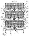
- a preferred embodiment according to the invention comprises three poultry residence areas 10a, b, c which are staggered vertically with respect to one another.
- Each poultry residence area 10a, b, c has support surfaces 11a, b, c shaped like a gently sloping gable roof, which, starting from the central longitudinal axis, run obliquely downward to the sides.
- These inclined contact surfaces serve as standing areas for chickens in the animal accommodation area and have the effect that eggs laid within the animal accommodation areas roll on both sides in egg belts 12a, b, c, 13a, b, c and can be collected there.
- the animal contact areas 11a, b, c are designed as gratings and are therefore permeable to the faeces deposited by the animals that stand on or above them.
- a manure belt 20a, b, c is arranged below each animal footprint 11a, b, c, which executes a conveying movement as an endless conveyor belt in the longitudinal direction, that is to say along the longitudinal axis L.
- On the The upwardly facing surface of the upper run 20a ', b', c 'of this manure belt 20a, b, c collects the falling animal manure. Below a transverse strut level, the manure belt is returned as a lower strand 20a ", b", c "in the opposite longitudinal direction.
- a free space 30a, b, c is present between the animal standing surface 11a, b, c and the manure belt 20a, b, c.
- a drying device 40a, b, c is arranged in this free space 30a, b, c and can move therein.
- Fig. 2 shows the drying device 40a, b, c of the animal keeping device according to FIG Fig. 1 .
- Essential parts of the animal accommodation areas such as the animal standing areas 11a, b, c, the side walls delimiting the animal accommodation area, egg collecting belts and various frame parts are not shown in order to make the individual parts of the drying device easier to see.
- Only the middle animal residence area 10b is shown schematically as a cuboid space.
- the drying device is explained below with regard to its detailed structure in each individual level on the basis of the lowest level.
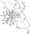
- the drying device 40a, b, c comprises a plurality of fan elements 41a-e in each level of the animal keeping device.
- Each fan element 41a-e comprises two plate-shaped components 42, 43 which, starting from a pivot axis 44a-e, extend in the radial direction. These pivot axes 44a-e are spaced apart from one another in the longitudinal direction and lie in a line which extends in the longitudinal direction L.
- the plate-shaped elements 42, 43 lie in a vertical plane.
- the pivot axes 44a-e are oriented vertically.
- the pivot axes 44a-e therefore run parallel to the surfaces of the plate-shaped components 42, 43.
- Both plate-shaped components 42, 43 are dimensioned to be of the same length in the axial and radial direction in relation to the pivot axes 44a-e.
- Fig. 2 the fan elements formed by the plate-shaped components 42, 43 are shown in an orientation in which they lie parallel to the longitudinal direction L. From this alignment, the fan elements can be pivoted about the pivot axes 44a-e. For this purpose, a cable mechanism 50a-c is provided in each of the three levels.
- the cable mechanism 50a-c serves as a coupling to a drive unit 51.
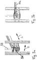
- This drive unit 51 comprises an electric motor 52 which drives a vertical shaft 53 and sets it in a continuous rotary movement.
- Figure 3A shows a crank mechanism 54, which converts the continuous rotary movement of the shaft 53 into a reciprocal pulling movement of the cable device 50a, b, c.
- crank gear 54 By means of the crank gear 54, the continuous rotary movement of the drive shaft 53 is translated into a reciprocal movement of the cables 50a-c.
- the transmission mechanism designed as a revolving cable 50a, b, c moves in such a way that one cable section 50c 'of the cable loop deflected at the rear end is pulled in a first longitudinal direction and the other cable section 50c "is moved in the opposite direction in a second longitudinal direction and this form of movement is then reversed and one cable 50c 'is moved in the second longitudinal direction and the other cable 50c "moves in the first longitudinal direction.
- Fig. 5 shows the deflection of one cable section 50c 'into the other cable section 50c "by means of a deflection pulley 55, the vertically aligned axis of rotation of which is fastened via a tension spring 56 to a cross strut at the longitudinally rear end of the animal keeping device applied a bias and thereby held taut.
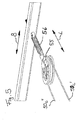
- Fig. 4 shows a fan element 41.
- the fan element comprises a fastening device 45 formed in the area of the pivot axis 44, which receives the plate-shaped element 42 in a slot 45a on one side of the pivot axis 44 and the plate-shaped element 43 in an opposite one with respect to the pivot axis 44 Slot 45b receives.
- the plate-shaped elements 42, 43 are provided with a transverse web at their end facing the pivot axis 44 and thereby each anchored positively in a corresponding groove 45a 'in the fastening element 45 and prevented from slipping out of the slot in the radial direction with respect to the pivot axis 44 .
- the plate-shaped elements 42, 43 can be made of thermoplastic elastomers, for example polyamide, polyethylene, polypropylene or mixtures based thereon, and thus be both elastically deformable and resistant to chemicals and correspondingly less susceptible to material fatigue in continuous operation.
- the material thickness of the plate-shaped elements tapers in the radial direction outwards from a thickness radially inside D i to a thickness radially outside D a , in order to obtain a uniform bending behavior of the plate-shaped elements.
- the plate-shaped elements 42, 43 deform about vertical bending axes, that is to say bending axes running parallel to the pivot axis 44.
- each of the two cable pull receptacles 73, 74 has a cable receiving section in which a pull cable which extends perpendicular to the pivot axis 44 can be fastened.
- this is achieved by two cable receiving sections 75, 76 spaced apart from one another in the longitudinal direction of the cable to be received, between which a cable clamping mechanism can be firmly fixed on the cable in a space 77, which means that the cable does not move in the longitudinal direction within the cable receiving devices 73, 74 can move.
- the fan element By alternately pulling the cantilever arms 71, 72 by means of the cable 50c, the fan element can be set in a reciprocally executed fan movement, in which the plate-shaped components 42, 43 are moved in the manner of a fan in a predetermined angular range and thereby fan drying air.
- This drying air causes efficient drying of the animal manure on the upper run of the manure belt below.
- the length of the plate-shaped elements 42, 43 in the radial direction is selected in the embodiment shown so that it is smaller than half the width of the animal keeping device in the width direction B.
- the length of the plate-like elements 42, 43 can also be designed to be greater than half the width of the animal keeping device. In such a case, it is preferred to execute a pivot angle of, for example, only 90 °, i.e. +/- 45 °, around the central position shown in the figures, thereby preventing the plate-shaped elements 42, 43 from protruding at the reversal points of the pivoting movement.
Landscapes
- Life Sciences & Earth Sciences (AREA)
- Environmental Sciences (AREA)
- Birds (AREA)
- Animal Husbandry (AREA)
- Biodiversity & Conservation Biology (AREA)
- Zoology (AREA)
- Engineering & Computer Science (AREA)
- Mechanical Engineering (AREA)
- General Engineering & Computer Science (AREA)
- Hydrology & Water Resources (AREA)
- Water Supply & Treatment (AREA)
- Chemical & Material Sciences (AREA)
- Organic Chemistry (AREA)
- Environmental & Geological Engineering (AREA)
- Microbiology (AREA)
- Housing For Livestock And Birds (AREA)
- Drying Of Solid Materials (AREA)
Priority Applications (1)
| Application Number | Priority Date | Filing Date | Title |
|---|---|---|---|
| PL19171306T PL3563676T3 (pl) | 2018-04-30 | 2019-04-26 | Urządzenie do hodowli drobiu z urządzeniem suszącym |
Applications Claiming Priority (1)
| Application Number | Priority Date | Filing Date | Title |
|---|---|---|---|
| DE202018102416.7U DE202018102416U1 (de) | 2018-04-30 | 2018-04-30 | Geflügelhaltungsvorrichtung mit Trocknungsvorrichtung |
Publications (2)
| Publication Number | Publication Date |
|---|---|
| EP3563676A1 EP3563676A1 (de) | 2019-11-06 |
| EP3563676B1 true EP3563676B1 (de) | 2021-03-10 |
Family
ID=66290274
Family Applications (1)
| Application Number | Title | Priority Date | Filing Date |
|---|---|---|---|
| EP19171306.4A Active EP3563676B1 (de) | 2018-04-30 | 2019-04-26 | Geflügelhaltungsvorrichtung mit trocknungsvorrichtung |
Country Status (9)
| Country | Link |
|---|---|
| US (1) | US11197465B2 (pl) |
| EP (1) | EP3563676B1 (pl) |
| JP (1) | JP7002495B2 (pl) |
| CN (1) | CN110402842B (pl) |
| DE (1) | DE202018102416U1 (pl) |
| ES (1) | ES2872973T3 (pl) |
| PL (1) | PL3563676T3 (pl) |
| RU (1) | RU2770593C2 (pl) |
| UA (1) | UA127711C2 (pl) |
Families Citing this family (8)
| Publication number | Priority date | Publication date | Assignee | Title |
|---|---|---|---|---|
| DE202017105052U1 (de) * | 2017-08-23 | 2017-11-09 | Franz Josef Kühlmann | Steckbare Geflügelhaltungsanlage |
| DE102018114037A1 (de) * | 2018-06-12 | 2019-12-12 | Salmet Gmbh & Co Kg | Käfigbatterie für die Geflügelhaltung |
| CN114009367B (zh) * | 2021-11-27 | 2025-07-08 | 贵州宏晟土山养殖有限公司 | 一种立体多层复合式养殖圈舍 |
| KR20240148314A (ko) * | 2022-02-10 | 2024-10-11 | 가부시키가이샤 하이템 | 계분건조장치 부착 케이지 구조 |
| CN115104549B (zh) * | 2022-08-02 | 2024-01-05 | 江苏省农业科学院 | 一种多平层、智能化、环保型肉用水禽养殖结构 |
| CN115638621B (zh) * | 2022-10-24 | 2024-07-26 | 浦北县金浦龙茶业有限公司 | 一种基于温度传感器的智能调节式烘干装置 |
| CN115823833B (zh) * | 2022-12-26 | 2023-08-01 | 四川轻化工大学 | 一种预绞式金具快速晾干装置 |
| CN116649245A (zh) * | 2023-07-19 | 2023-08-29 | 广州广兴牧业设备集团有限公司 | 一种笼养装置 |
Family Cites Families (25)
| Publication number | Priority date | Publication date | Assignee | Title |
|---|---|---|---|---|
| US3268067A (en) | 1965-06-14 | 1966-08-23 | Klinzing Co Inc A F | Feed distributor |
| AT382862B (de) | 1985-02-01 | 1987-04-27 | Erich Eigner | Verfahren und vorrichtung zum trocknen und konditionieren von huehnermist oder aehnlichen pastoesen stoffen |
| US5036797A (en) * | 1986-03-26 | 1991-08-06 | Koozer Howard D | Animal husbandry housing and method |
| DE3908336A1 (de) * | 1989-03-15 | 1990-09-20 | Salmet Gmbh & Co Kg | Antrieb fuer luftstroemungseinrichtung einer kaefigbatterie fuer die gefluegelhaltung |
| RU2035676C1 (ru) * | 1991-04-29 | 1995-05-20 | Открытое акционерное общество "Житомирдрев" | Веерная сушилка |
| ES2065788B1 (es) * | 1991-05-28 | 1995-08-01 | Ansoain Burguete S L | Instalacion de aireacion para baterias de jaulas de aves. |
| ES2036482B1 (es) * | 1991-11-12 | 1994-04-01 | Mas Antonio Saura | Bateria de jaulas para aves. |
| US5410985A (en) * | 1992-01-21 | 1995-05-02 | Chick Master Incubator Company | Poultry incubator and method |
| FR2693628A1 (fr) * | 1992-07-15 | 1994-01-21 | Danno Ateliers | Dispositif de ventilation pour une batterie de cages d'élevage de volailles et batterie ainsi équipée. |
| JP3499015B2 (ja) * | 1994-10-19 | 2004-02-23 | 東洋システム株式会社 | 鶏舎の鶏糞乾燥装置 |
| DE69600067T2 (de) * | 1995-05-03 | 1998-05-07 | Tecno Impianti Avicoli Srl | Batteriekäfig für Geflügel |
| DE19634126B4 (de) | 1995-08-26 | 2006-01-05 | Salmet Gmbh & Co Kg | Käfigbatterie für die Geflügelhaltung |
| US5950565A (en) * | 1995-09-22 | 1999-09-14 | Guyot; Jean Noel | Animal husbandry containment apparatus |
| FR2746587A1 (fr) * | 1996-04-01 | 1997-10-03 | Le Tallec Sa Ets | Dispositif de ventilation de fientes de volailles |
| US20050150747A1 (en) | 2004-01-14 | 2005-07-14 | Hewlett-Packard Development Company, L.P. | Belt tracking |
| JP3992707B2 (ja) * | 2004-10-22 | 2007-10-17 | ヨシダエルシス株式会社 | 鶏糞乾燥装置 |
| US8210126B2 (en) * | 2006-12-01 | 2012-07-03 | Yik Hei Sia | Swiftlets farming for production of edible bird's nests |
| DE202007003455U1 (de) | 2007-03-06 | 2007-05-16 | Big Dutchman International Gmbh | Käfiganordnung für Geflügel, vorzugsweise für Masthähnchen (Broiler) |
| DE202007008362U1 (de) | 2007-06-11 | 2007-09-06 | Big Dutchman International Gmbh | Trocknungsvorrichtung für pastöse oder körnige Stoffe |
| US8127918B2 (en) | 2008-01-22 | 2012-03-06 | Barge's Belting Solution Pty Ltd | Method and apparatus for monitoring a conveyor belt |
| CN102227594A (zh) * | 2008-10-29 | 2011-10-26 | 海区特克集团股份有限公司 | 用于调节气候室的温度的方法以及气候室 |
| EP2377787B1 (de) | 2010-04-16 | 2013-03-20 | Joseph Vögele AG | Bandfördereinrichtung |
| DE202012010693U1 (de) | 2012-11-09 | 2014-02-10 | Big Dutchman International Gmbh | Tunnel-Trocknungsvorrichtung für Schüttgut |
| DE202014000575U1 (de) | 2014-01-24 | 2014-03-25 | Big Dutchman International Gmbh | Luftkanal zur Trocknung von Legehennenexkrementen |
| CN107743893A (zh) | 2017-11-22 | 2018-03-02 | 河北新裕德畜牧机械科技有限公司 | 一种鸡笼内摆风干粪系统 |
-
2018
- 2018-04-30 DE DE202018102416.7U patent/DE202018102416U1/de active Active
-
2019
- 2019-04-25 UA UAA201904496A patent/UA127711C2/uk unknown
- 2019-04-25 RU RU2019112744A patent/RU2770593C2/ru active
- 2019-04-26 PL PL19171306T patent/PL3563676T3/pl unknown
- 2019-04-26 ES ES19171306T patent/ES2872973T3/es active Active
- 2019-04-26 JP JP2019085281A patent/JP7002495B2/ja active Active
- 2019-04-26 EP EP19171306.4A patent/EP3563676B1/de active Active
- 2019-04-29 US US16/397,523 patent/US11197465B2/en active Active
- 2019-04-30 CN CN201910365073.3A patent/CN110402842B/zh active Active
Non-Patent Citations (1)
| Title |
|---|
| None * |
Also Published As
| Publication number | Publication date |
|---|---|
| UA127711C2 (uk) | 2023-12-13 |
| ES2872973T3 (es) | 2021-11-03 |
| CN110402842A (zh) | 2019-11-05 |
| US20190327940A1 (en) | 2019-10-31 |
| DE202018102416U1 (de) | 2019-07-31 |
| JP2019193631A (ja) | 2019-11-07 |
| EP3563676A1 (de) | 2019-11-06 |
| CN110402842B (zh) | 2023-01-03 |
| US11197465B2 (en) | 2021-12-14 |
| RU2019112744A3 (pl) | 2021-11-18 |
| RU2019112744A (ru) | 2020-10-26 |
| RU2770593C2 (ru) | 2022-04-18 |
| PL3563676T3 (pl) | 2021-08-02 |
| JP7002495B2 (ja) | 2022-01-20 |
Similar Documents
| Publication | Publication Date | Title |
|---|---|---|
| EP3563676B1 (de) | Geflügelhaltungsvorrichtung mit trocknungsvorrichtung | |
| EP0299015B1 (de) | Käfiganlage für geflügelzuchtbetriebe | |
| DE102010025845A1 (de) | Solaranlagenreinigungsvorrichtung | |
| DE202012010693U1 (de) | Tunnel-Trocknungsvorrichtung für Schüttgut | |
| DE1582642A1 (de) | Maehdrescher | |
| WO2015177198A1 (de) | Armeinrichtung für eine melkstandanordnung zum automatischen melken von milchgebenden tieren, platzteiler einer melkstandanordnung und melkstandanordnung | |
| EP0387819B1 (de) | Antrieb für Luftströmungseinrichtung einer Käfigbatterie für die Geflügelhaltung | |
| DE19634126B4 (de) | Käfigbatterie für die Geflügelhaltung | |
| EP1524895B1 (de) | Kotfördereinrichtung für tierzuchtbetriebe und verfahren zum betreiben einer solchen einrichtung | |
| DE69600067T2 (de) | Batteriekäfig für Geflügel | |
| DE102016220437A1 (de) | Reinigungsanordnung für Tragflächenvorderkanten | |
| EP0212269B1 (de) | Mähdrescher mit Anbauhäcksler | |
| DE3715735C2 (de) | Käfigbatterie für die Geflügelhaltung | |
| DE2703968C2 (de) | Einrichtung zur Aufzucht von Geflügel in einem Stall | |
| DE3541976A1 (de) | Aufbereiterwalze | |
| DE8313760U1 (de) | Heissluftbehandlungsvorrichtung fuer kontinuierlich transportiertes textilgut | |
| DE4313456C1 (de) | Käfiganlage für Geflügelzuchtbetriebe | |
| DE102008021784A1 (de) | Erntemaschine mit Schrägförderer | |
| WO2019238156A1 (de) | Käfigbatterie für die geflügelhaltung | |
| DE102023125494B3 (de) | Vorrichtung und Verfahren zum Reinigen eines Tierstalls | |
| DE102024121229B3 (de) | Solaranlageninstallation | |
| DE102023125497B3 (de) | Vorrichtung und Verfahren zum Aufbringen von Streumaterial bei der Tierhaltung | |
| EP4691227A1 (de) | Kotfördervorrichtung, insbesondere für den einsatz bei legehennenbodenhaltung oder hähnchenmast | |
| DE3719465C2 (pl) | ||
| DE19948057A1 (de) | Volieren- oder Großkäfiganlage, insbesondere für Legehennen |
Legal Events
| Date | Code | Title | Description |
|---|---|---|---|
| PUAI | Public reference made under article 153(3) epc to a published international application that has entered the european phase |
Free format text: ORIGINAL CODE: 0009012 |
|
| STAA | Information on the status of an ep patent application or granted ep patent |
Free format text: STATUS: THE APPLICATION HAS BEEN PUBLISHED |
|
| AK | Designated contracting states |
Kind code of ref document: A1 Designated state(s): AL AT BE BG CH CY CZ DE DK EE ES FI FR GB GR HR HU IE IS IT LI LT LU LV MC MK MT NL NO PL PT RO RS SE SI SK SM TR |
|
| AX | Request for extension of the european patent |
Extension state: BA ME |
|
| STAA | Information on the status of an ep patent application or granted ep patent |
Free format text: STATUS: REQUEST FOR EXAMINATION WAS MADE |
|
| 17P | Request for examination filed |
Effective date: 20200506 |
|
| RBV | Designated contracting states (corrected) |
Designated state(s): AL AT BE BG CH CY CZ DE DK EE ES FI FR GB GR HR HU IE IS IT LI LT LU LV MC MK MT NL NO PL PT RO RS SE SI SK SM TR |
|
| RIC1 | Information provided on ipc code assigned before grant |
Ipc: A01K 31/04 20060101AFI20200608BHEP Ipc: F26B 3/04 20060101ALI20200608BHEP Ipc: F26B 17/04 20060101ALI20200608BHEP |
|
| GRAP | Despatch of communication of intention to grant a patent |
Free format text: ORIGINAL CODE: EPIDOSNIGR1 |
|
| STAA | Information on the status of an ep patent application or granted ep patent |
Free format text: STATUS: GRANT OF PATENT IS INTENDED |
|
| INTG | Intention to grant announced |
Effective date: 20200918 |
|
| GRAS | Grant fee paid |
Free format text: ORIGINAL CODE: EPIDOSNIGR3 |
|
| GRAA | (expected) grant |
Free format text: ORIGINAL CODE: 0009210 |
|
| STAA | Information on the status of an ep patent application or granted ep patent |
Free format text: STATUS: THE PATENT HAS BEEN GRANTED |
|
| AK | Designated contracting states |
Kind code of ref document: B1 Designated state(s): AL AT BE BG CH CY CZ DE DK EE ES FI FR GB GR HR HU IE IS IT LI LT LU LV MC MK MT NL NO PL PT RO RS SE SI SK SM TR |
|
| REG | Reference to a national code |
Ref country code: GB Ref legal event code: FG4D Free format text: NOT ENGLISH |
|
| REG | Reference to a national code |
Ref country code: CH Ref legal event code: EP Ref country code: AT Ref legal event code: REF Ref document number: 1368752 Country of ref document: AT Kind code of ref document: T Effective date: 20210315 |
|
| REG | Reference to a national code |
Ref country code: IE Ref legal event code: FG4D Free format text: LANGUAGE OF EP DOCUMENT: GERMAN |
|
| REG | Reference to a national code |
Ref country code: DE Ref legal event code: R096 Ref document number: 502019000953 Country of ref document: DE |
|
| REG | Reference to a national code |
Ref country code: NL Ref legal event code: FP |
|
| REG | Reference to a national code |
Ref country code: LT Ref legal event code: MG9D |
|
| PG25 | Lapsed in a contracting state [announced via postgrant information from national office to epo] |
Ref country code: BG Free format text: LAPSE BECAUSE OF FAILURE TO SUBMIT A TRANSLATION OF THE DESCRIPTION OR TO PAY THE FEE WITHIN THE PRESCRIBED TIME-LIMIT Effective date: 20210610 Ref country code: FI Free format text: LAPSE BECAUSE OF FAILURE TO SUBMIT A TRANSLATION OF THE DESCRIPTION OR TO PAY THE FEE WITHIN THE PRESCRIBED TIME-LIMIT Effective date: 20210310 Ref country code: HR Free format text: LAPSE BECAUSE OF FAILURE TO SUBMIT A TRANSLATION OF THE DESCRIPTION OR TO PAY THE FEE WITHIN THE PRESCRIBED TIME-LIMIT Effective date: 20210310 Ref country code: GR Free format text: LAPSE BECAUSE OF FAILURE TO SUBMIT A TRANSLATION OF THE DESCRIPTION OR TO PAY THE FEE WITHIN THE PRESCRIBED TIME-LIMIT Effective date: 20210611 Ref country code: LT Free format text: LAPSE BECAUSE OF FAILURE TO SUBMIT A TRANSLATION OF THE DESCRIPTION OR TO PAY THE FEE WITHIN THE PRESCRIBED TIME-LIMIT Effective date: 20210310 Ref country code: NO Free format text: LAPSE BECAUSE OF FAILURE TO SUBMIT A TRANSLATION OF THE DESCRIPTION OR TO PAY THE FEE WITHIN THE PRESCRIBED TIME-LIMIT Effective date: 20210610 |
|
| PG25 | Lapsed in a contracting state [announced via postgrant information from national office to epo] |
Ref country code: LV Free format text: LAPSE BECAUSE OF FAILURE TO SUBMIT A TRANSLATION OF THE DESCRIPTION OR TO PAY THE FEE WITHIN THE PRESCRIBED TIME-LIMIT Effective date: 20210310 Ref country code: RS Free format text: LAPSE BECAUSE OF FAILURE TO SUBMIT A TRANSLATION OF THE DESCRIPTION OR TO PAY THE FEE WITHIN THE PRESCRIBED TIME-LIMIT Effective date: 20210310 Ref country code: SE Free format text: LAPSE BECAUSE OF FAILURE TO SUBMIT A TRANSLATION OF THE DESCRIPTION OR TO PAY THE FEE WITHIN THE PRESCRIBED TIME-LIMIT Effective date: 20210310 |
|
| PG25 | Lapsed in a contracting state [announced via postgrant information from national office to epo] |
Ref country code: EE Free format text: LAPSE BECAUSE OF FAILURE TO SUBMIT A TRANSLATION OF THE DESCRIPTION OR TO PAY THE FEE WITHIN THE PRESCRIBED TIME-LIMIT Effective date: 20210310 Ref country code: CZ Free format text: LAPSE BECAUSE OF FAILURE TO SUBMIT A TRANSLATION OF THE DESCRIPTION OR TO PAY THE FEE WITHIN THE PRESCRIBED TIME-LIMIT Effective date: 20210310 Ref country code: SM Free format text: LAPSE BECAUSE OF FAILURE TO SUBMIT A TRANSLATION OF THE DESCRIPTION OR TO PAY THE FEE WITHIN THE PRESCRIBED TIME-LIMIT Effective date: 20210310 |
|
| REG | Reference to a national code |
Ref country code: ES Ref legal event code: FG2A Ref document number: 2872973 Country of ref document: ES Kind code of ref document: T3 Effective date: 20211103 |
|
| PG25 | Lapsed in a contracting state [announced via postgrant information from national office to epo] |
Ref country code: IS Free format text: LAPSE BECAUSE OF FAILURE TO SUBMIT A TRANSLATION OF THE DESCRIPTION OR TO PAY THE FEE WITHIN THE PRESCRIBED TIME-LIMIT Effective date: 20210710 Ref country code: PT Free format text: LAPSE BECAUSE OF FAILURE TO SUBMIT A TRANSLATION OF THE DESCRIPTION OR TO PAY THE FEE WITHIN THE PRESCRIBED TIME-LIMIT Effective date: 20210712 Ref country code: RO Free format text: LAPSE BECAUSE OF FAILURE TO SUBMIT A TRANSLATION OF THE DESCRIPTION OR TO PAY THE FEE WITHIN THE PRESCRIBED TIME-LIMIT Effective date: 20210310 Ref country code: SK Free format text: LAPSE BECAUSE OF FAILURE TO SUBMIT A TRANSLATION OF THE DESCRIPTION OR TO PAY THE FEE WITHIN THE PRESCRIBED TIME-LIMIT Effective date: 20210310 |
|
| REG | Reference to a national code |
Ref country code: DE Ref legal event code: R097 Ref document number: 502019000953 Country of ref document: DE |
|
| PG25 | Lapsed in a contracting state [announced via postgrant information from national office to epo] |
Ref country code: LU Free format text: LAPSE BECAUSE OF NON-PAYMENT OF DUE FEES Effective date: 20210426 |
|
| PLBE | No opposition filed within time limit |
Free format text: ORIGINAL CODE: 0009261 |
|
| STAA | Information on the status of an ep patent application or granted ep patent |
Free format text: STATUS: NO OPPOSITION FILED WITHIN TIME LIMIT |
|
| REG | Reference to a national code |
Ref country code: BE Ref legal event code: MM Effective date: 20210430 |
|
| PG25 | Lapsed in a contracting state [announced via postgrant information from national office to epo] |
Ref country code: AL Free format text: LAPSE BECAUSE OF FAILURE TO SUBMIT A TRANSLATION OF THE DESCRIPTION OR TO PAY THE FEE WITHIN THE PRESCRIBED TIME-LIMIT Effective date: 20210310 Ref country code: DK Free format text: LAPSE BECAUSE OF FAILURE TO SUBMIT A TRANSLATION OF THE DESCRIPTION OR TO PAY THE FEE WITHIN THE PRESCRIBED TIME-LIMIT Effective date: 20210310 Ref country code: MC Free format text: LAPSE BECAUSE OF FAILURE TO SUBMIT A TRANSLATION OF THE DESCRIPTION OR TO PAY THE FEE WITHIN THE PRESCRIBED TIME-LIMIT Effective date: 20210310 |
|
| 26N | No opposition filed |
Effective date: 20211213 |
|
| PG25 | Lapsed in a contracting state [announced via postgrant information from national office to epo] |
Ref country code: SI Free format text: LAPSE BECAUSE OF FAILURE TO SUBMIT A TRANSLATION OF THE DESCRIPTION OR TO PAY THE FEE WITHIN THE PRESCRIBED TIME-LIMIT Effective date: 20210310 |
|
| PG25 | Lapsed in a contracting state [announced via postgrant information from national office to epo] |
Ref country code: IE Free format text: LAPSE BECAUSE OF NON-PAYMENT OF DUE FEES Effective date: 20210426 |
|
| PG25 | Lapsed in a contracting state [announced via postgrant information from national office to epo] |
Ref country code: IS Free format text: LAPSE BECAUSE OF FAILURE TO SUBMIT A TRANSLATION OF THE DESCRIPTION OR TO PAY THE FEE WITHIN THE PRESCRIBED TIME-LIMIT Effective date: 20210710 |
|
| PG25 | Lapsed in a contracting state [announced via postgrant information from national office to epo] |
Ref country code: BE Free format text: LAPSE BECAUSE OF NON-PAYMENT OF DUE FEES Effective date: 20210430 |
|
| REG | Reference to a national code |
Ref country code: CH Ref legal event code: PL |
|
| PG25 | Lapsed in a contracting state [announced via postgrant information from national office to epo] |
Ref country code: LI Free format text: LAPSE BECAUSE OF NON-PAYMENT OF DUE FEES Effective date: 20220430 Ref country code: CH Free format text: LAPSE BECAUSE OF NON-PAYMENT OF DUE FEES Effective date: 20220430 |
|
| P01 | Opt-out of the competence of the unified patent court (upc) registered |
Effective date: 20230523 |
|
| PG25 | Lapsed in a contracting state [announced via postgrant information from national office to epo] |
Ref country code: CY Free format text: LAPSE BECAUSE OF FAILURE TO SUBMIT A TRANSLATION OF THE DESCRIPTION OR TO PAY THE FEE WITHIN THE PRESCRIBED TIME-LIMIT Effective date: 20210310 |
|
| PG25 | Lapsed in a contracting state [announced via postgrant information from national office to epo] |
Ref country code: HU Free format text: LAPSE BECAUSE OF FAILURE TO SUBMIT A TRANSLATION OF THE DESCRIPTION OR TO PAY THE FEE WITHIN THE PRESCRIBED TIME-LIMIT; INVALID AB INITIO Effective date: 20190426 |
|
| PG25 | Lapsed in a contracting state [announced via postgrant information from national office to epo] |
Ref country code: MK Free format text: LAPSE BECAUSE OF FAILURE TO SUBMIT A TRANSLATION OF THE DESCRIPTION OR TO PAY THE FEE WITHIN THE PRESCRIBED TIME-LIMIT Effective date: 20210310 |
|
| PG25 | Lapsed in a contracting state [announced via postgrant information from national office to epo] |
Ref country code: MT Free format text: LAPSE BECAUSE OF FAILURE TO SUBMIT A TRANSLATION OF THE DESCRIPTION OR TO PAY THE FEE WITHIN THE PRESCRIBED TIME-LIMIT Effective date: 20210310 |
|
| PGFP | Annual fee paid to national office [announced via postgrant information from national office to epo] |
Ref country code: PL Payment date: 20250224 Year of fee payment: 7 |
|
| PGFP | Annual fee paid to national office [announced via postgrant information from national office to epo] |
Ref country code: NL Payment date: 20250422 Year of fee payment: 7 |
|
| REG | Reference to a national code |
Ref country code: AT Ref legal event code: MM01 Ref document number: 1368752 Country of ref document: AT Kind code of ref document: T Effective date: 20240426 |
|
| PGFP | Annual fee paid to national office [announced via postgrant information from national office to epo] |
Ref country code: DE Payment date: 20250507 Year of fee payment: 7 |
|
| PGFP | Annual fee paid to national office [announced via postgrant information from national office to epo] |
Ref country code: ES Payment date: 20250519 Year of fee payment: 7 |
|
| PGFP | Annual fee paid to national office [announced via postgrant information from national office to epo] |
Ref country code: IT Payment date: 20250430 Year of fee payment: 7 |
|
| PGFP | Annual fee paid to national office [announced via postgrant information from national office to epo] |
Ref country code: FR Payment date: 20250425 Year of fee payment: 7 |
|
| PG25 | Lapsed in a contracting state [announced via postgrant information from national office to epo] |
Ref country code: AT Free format text: LAPSE BECAUSE OF NON-PAYMENT OF DUE FEES Effective date: 20240426 |
|
| PGFP | Annual fee paid to national office [announced via postgrant information from national office to epo] |
Ref country code: TR Payment date: 20250418 Year of fee payment: 7 |
|
| PGFP | Annual fee paid to national office [announced via postgrant information from national office to epo] |
Ref country code: GB Payment date: 20260324 Year of fee payment: 8 |
|
| PGFP | Annual fee paid to national office [announced via postgrant information from national office to epo] |
Ref country code: AT Payment date: 20260410 Year of fee payment: 5 |