EP3563205B1 - System und verfahren zur überwachung des bereichs unter einem autonomen fahrzeug und zum erlauben autonomen fahrens - Google Patents
System und verfahren zur überwachung des bereichs unter einem autonomen fahrzeug und zum erlauben autonomen fahrens Download PDFInfo
- Publication number
- EP3563205B1 EP3563205B1 EP17825223.5A EP17825223A EP3563205B1 EP 3563205 B1 EP3563205 B1 EP 3563205B1 EP 17825223 A EP17825223 A EP 17825223A EP 3563205 B1 EP3563205 B1 EP 3563205B1
- Authority
- EP
- European Patent Office
- Prior art keywords
- autonomous vehicle
- topography
- autonomous
- ground surface
- underneath
- Prior art date
- Legal status (The legal status is an assumption and is not a legal conclusion. Google has not performed a legal analysis and makes no representation as to the accuracy of the status listed.)
- Active
Links
Images


Classifications
-
- G—PHYSICS
- G05—CONTROLLING; REGULATING
- G05D—SYSTEMS FOR CONTROLLING OR REGULATING NON-ELECTRIC VARIABLES
- G05D1/00—Control of position, course, altitude or attitude of land, water, air or space vehicles, e.g. using automatic pilots
- G05D1/0055—Control of position, course, altitude or attitude of land, water, air or space vehicles, e.g. using automatic pilots with safety arrangements
- G05D1/0061—Control of position, course, altitude or attitude of land, water, air or space vehicles, e.g. using automatic pilots with safety arrangements for transition from automatic pilot to manual pilot and vice versa
-
- B—PERFORMING OPERATIONS; TRANSPORTING
- B60—VEHICLES IN GENERAL
- B60W—CONJOINT CONTROL OF VEHICLE SUB-UNITS OF DIFFERENT TYPE OR DIFFERENT FUNCTION; CONTROL SYSTEMS SPECIALLY ADAPTED FOR HYBRID VEHICLES; ROAD VEHICLE DRIVE CONTROL SYSTEMS FOR PURPOSES NOT RELATED TO THE CONTROL OF A PARTICULAR SUB-UNIT
- B60W40/00—Estimation or calculation of non-directly measurable driving parameters for road vehicle drive control systems not related to the control of a particular sub unit, e.g. by using mathematical models
- B60W40/02—Estimation or calculation of non-directly measurable driving parameters for road vehicle drive control systems not related to the control of a particular sub unit, e.g. by using mathematical models related to ambient conditions
- B60W40/06—Road conditions
-
- G—PHYSICS
- G05—CONTROLLING; REGULATING
- G05D—SYSTEMS FOR CONTROLLING OR REGULATING NON-ELECTRIC VARIABLES
- G05D1/00—Control of position, course, altitude or attitude of land, water, air or space vehicles, e.g. using automatic pilots
- G05D1/80—Arrangements for reacting to or preventing system or operator failure
-
- G—PHYSICS
- G05—CONTROLLING; REGULATING
- G05D—SYSTEMS FOR CONTROLLING OR REGULATING NON-ELECTRIC VARIABLES
- G05D1/00—Control of position, course, altitude or attitude of land, water, air or space vehicles, e.g. using automatic pilots
- G05D1/60—Intended control result
- G05D1/617—Safety or protection, e.g. defining protection zones around obstacles or avoiding hazards
-
- G—PHYSICS
- G06—COMPUTING OR CALCULATING; COUNTING
- G06V—IMAGE OR VIDEO RECOGNITION OR UNDERSTANDING
- G06V20/00—Scenes; Scene-specific elements
- G06V20/50—Context or environment of the image
- G06V20/56—Context or environment of the image exterior to a vehicle by using sensors mounted on the vehicle
- G06V20/58—Recognition of moving objects or obstacles, e.g. vehicles or pedestrians; Recognition of traffic objects, e.g. traffic signs, traffic lights or roads
-
- G—PHYSICS
- G07—CHECKING-DEVICES
- G07C—TIME OR ATTENDANCE REGISTERS; REGISTERING OR INDICATING THE WORKING OF MACHINES; GENERATING RANDOM NUMBERS; VOTING OR LOTTERY APPARATUS; ARRANGEMENTS, SYSTEMS OR APPARATUS FOR CHECKING NOT PROVIDED FOR ELSEWHERE
- G07C5/00—Registering or indicating the working of vehicles
- G07C5/008—Registering or indicating the working of vehicles communicating information to a remotely located station
-
- G—PHYSICS
- G05—CONTROLLING; REGULATING
- G05D—SYSTEMS FOR CONTROLLING OR REGULATING NON-ELECTRIC VARIABLES
- G05D2101/00—Details of software or hardware architectures used for the control of position
- G05D2101/10—Details of software or hardware architectures used for the control of position using artificial intelligence [AI] techniques
-
- G—PHYSICS
- G06—COMPUTING OR CALCULATING; COUNTING
- G06F—ELECTRIC DIGITAL DATA PROCESSING
- G06F18/00—Pattern recognition
- G06F18/20—Analysing
- G06F18/22—Matching criteria, e.g. proximity measures
Definitions
- Autonomous vehicles include external sensors that monitor the surroundings of the vehicle. When objects are detected by the sensors, control systems within the autonomous vehicle may provide automated maneuvering, stopping, and steering functions. However, external sensors are limited in their field of view and typically do not detect objects underneath the autonomous vehicle. In addition, these systems may demand a high level of system resources and processing time for detecting and tracking objects.
- JP 2016 074314 A provides a vehicular warning device configured to monitor an area underneath a vehicle, comprising capturing a first temperature distribution of the space under the stationary vehicle using a plurality of temperature detection cameras, storing the first topography prior to the vehicle being switched off, capturing a second temperature distribution when the intention of the driver to drive is detected, comparing the first and the second topography and issuing a warning when it is determined that there is a warm object of a size equal or above a predetermined size underneath the vehicle.
- DE 10 2015 201317 A1 provides a device for measuring a dimension between at least two points of a ground region underneath the vehicle, the device comprising an image-generating scanner, a display to output a representation of the surroundings of the vehicle, an input apparatus to define at least two points as measuring points between which a dimension is to be determined in the displayed representation, an environment sensor configured to sense a distance and a direction of each of the measuring points with respect to the vehicle.
- a method of monitoring an area underneath an autonomous vehicle includes capturing a first topography of a ground surface underneath the autonomous vehicle with a sensor when the autonomous vehicle is stationary; storing the topography of the ground surface in a memory prior to the autonomous vehicle being switched off; capturing a second topography of the ground surface underneath the autonomous vehicle with the sensor before the autonomous vehicle begins moving; and comparing, with an electronic processor, the first topography with the second topography.
- the method includes enabling autonomous driving of the autonomous vehicle when the first topography of the ground surface underneath the autonomous vehicle and the second topography of the ground surface underneath the autonomous vehicle match.
- the method includes disabling autonomous driving of the autonomous vehicle; generating an notification that autonomous driving is disabled; and sending the notification to a user of the autonomous vehicle and a remote monitoring service for the autonomous vehicle, when the first topography of the ground surface underneath the autonomous vehicle and the second topography of the ground surface underneath the autonomous vehicle are different.
- the comparing, by the electronic control unit, the first topography with the second topography includes determining a difference score indicative of an amount of differences detected between the first topography and the second topography.
- a system for monitoring an area underneath an autonomous vehicle includes a sensor with a field of view that extends underneath the autonomous vehicle, an input/output interface configured to communicatively connect to a notification device, and an electronic processor communicatively connected to the sensor and the input/output interface.
- the electronic processor is configured to capture a first topography of a ground surface underneath the autonomous vehicle with a sensor when the autonomous vehicle is stationary, store the topography of the ground surface in the memory of the electronic control unit prior to the autonomous vehicle being switched off, and capture a second topography of the ground surface underneath the autonomous vehicle with the sensor when the autonomous vehicle is switched on.
- the electronic processor is also configured to compare the first topography with the second topography and enable autonomous driving of the autonomous vehicle when the first topography and the second topography match.
- the electronic processor is also configured disable autonomous driving of the autonomous vehicle; generate an notification that autonomous driving is disabled; and send the notification to a user of the autonomous vehicle and a remote monitoring service for the autonomous vehicle, when the first topography of the ground surface underneath the autonomous vehicle and the second topography of the ground surface underneath the autonomous vehicle are different.
- the electronic processor is also configured determine a difference score indicative of an amount of differences detected between the first topography and the second topography.
- a plurality of hardware and software based devices may be used to implement various embodiments.
- embodiments may include hardware, software, and electronic components or modules that, for purposes of discussion, may be illustrated and described as if the majority of the components were implemented solely in hardware.
- the electronic based aspects of the invention may be implemented in software (for example, stored on non-transitory computer-readable medium) executable by one or more processors.
- control units and “controllers” described in the specification can include one or more electronic processors, one or more memory modules including non-transitory computer-readable medium, one or more input/output interfaces, one or more application specific integrated circuits (ASICs), and various connections (for example, a system bus) connecting the various components.
- ASICs application specific integrated circuits
- Fig. 1 illustrates an autonomous vehicle 100 equipped with a monitoring system 105 for monitoring an area underneath the autonomous vehicle 100 according to one embodiment.
- the autonomous vehicle 100 although illustrated as a four-wheeled vehicle, encompasses various types and designs.
- the autonomous vehicle 100 may include an automobile, a motorcycle, a truck, a bus, a semi-tractor, and others.
- the monitoring system 105 includes an electronic control unit (ECU) 110, a sensor 115 (for example, radar, lidar, ultrasound, infrared, and others), and a notification device 120 (described in greater detail below).
- ECU electronice control unit
- sensor 115 for example, radar, lidar, ultrasound, infrared, and others
- a notification device 120 described in greater detail below.
- the electronic control unit 110 is communicatively connected to the sensor 115 and the notification device 120.
- the electronic control unit 110 may be configured to communicate with the sensor 115 and the notification device 120 via various mechanisms or protocols.
- the electronic control unit 110 and the sensor 115 may be directly wired, wired through a communication bus, or wirelessly connected (for example, via a wireless network).
- the electronic control unit 110 and the notification device 120 may be connected via similar connections as those listed above or may be connected via a wide area network (for example, the internet), a cellular network, or others.
- the electronic control unit 110 is configured to receive information from the sensor 115 regarding the surroundings of the autonomous vehicle 100 and to generate notifications to send to the notification device 120.
- the notification device 120 may be of various different types and use various different technologies.
- the notification device 120 is mounted within the autonomous vehicle 100 and viewable by a user of the autonomous vehicle 100 (for example, mounted on the console, mounted within a seatback, mounted on the roof, etc.).
- the notification device 120 may include a display screen, a speaker, or other mechanism for creating an audial, visual, or haptic notification to the user.
- the notification device 120 may be separate from the vehicle 100, have other functionalities, and be configured to communicate with the electronic control unit 110.
- the notification device 120 may be a portable communication device of a user of the autonomous vehicle 100.
- the notification device 120 may be a computer terminal positioned at a remote monitoring service that controls, coordinates, or monitors performance of the autonomous vehicle 100.
- the notification device 120 includes an input mechanism for receiving a message from a user (for example, an "all-clear" message) and may be configured to send the message back to the electronic control unit 110 of the autonomous vehicle 100.
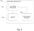
- Fig. 2 is a block diagram of an electronic control unit 110 of the monitoring system 105 according to one embodiment.
- the electronic control unit 110 includes a plurality of electrical and electronic components that provide power, operational control, and protection to the components and modules within the electronic control unit 110.
- the electronic control unit 110 includes, among other things, an electronic processor 210 (such as a programmable electronic microprocessor, microcontroller, or similar device), a memory 215, and an input/output interface 220.
- the term "memory 215" includes any type of non-transitory, machine-readable memory including various types of non-volatile memory.
- the memory 215 may include internal and external memory, hard drives, disks, and others.
- the electronic control unit 110 includes additional, fewer, or different components.
- the electronic control unit 110 may be implemented in several independent electronic control units or modules each configured to perform specific steps or functions of the electronic control unit 110.
- the electronic processor 210 in coordination with the memory 215, the input/output interface 220, and other components of the electronic control unit 110, is configured to perform the processes and methods discussed herein.
- the electronic processor 210 is configured to retrieve from memory 215 and execute, among other things, instructions related to receiving sensor data from the sensor 115, generating notifications for the notification device 120, and enabling/disabling autonomous control of the autonomous vehicle 100.
- the input/output interface 220 is configured to perform input/output functions for the electronic processor 210.
- the input/output interface 220 is configured to communicate with the sensor 115 and the notification device 120.
- Fig. 3 is a flowchart of a method of operating the autonomous vehicle 100 according to one embodiment.
- the electronic processor 210 first determines whether the autonomous vehicle is "stationary" (block 305). This may include determining whether the autonomous vehicle is in a state of any of the following conditions: parked, stopped, or shutting down. These conditions may be determined based on various operational parameters of the autonomous vehicle 100 including a location of the autonomous vehicle 100, an amount of time that the autonomous vehicle 100 is not moving, arrival at a predetermined destination, and others. In some embodiments, the determination of being "stationary" only occurs under one of the particular conditions.
- the electronic processor 210 sets a flag indicating that the autonomous vehicle is "stationary” only when the autonomous vehicle 100 is parked (for example, in the parked gear). In other embodiments, the electronic processor 210 sets a flag indicating that the autonomous vehicle 210 is "stationary” only when the autonomous vehicle 100 is not moving (for example, stopped) for more than a particular period of time. In yet other embodiments, the electronic processor 210 sets a flag indicating that the autonomous vehicle 100 is "stationary” only when the autonomous vehicle 100 is in the process of turning off (for example, in a power down sequence).
- the electronic processor 210 determines that the autonomous vehicle 100 is stationary, the electronic processor 210 captures a first topography of a ground surface underneath the autonomous vehicle 100 with the sensor 115 (block 310).
- the topography may be obtained by scanning the ground surface with the sensor 115.
- the sensor 115 may sense the distance to various points of the ground surface using a series of radio frequency reflections and create a topographical map based on the reflections.
- the sensor 115 includes a lidar scanner or high resolution radar scanner that senses the elevation of the autonomous vehicle 100 at multiple points underneath the autonomous vehicle 100.
- the sensor 115 includes an ultrasonic sensor, and the electronic processor 210 determines a distance to the ground at various points underneath the autonomous vehicle 100 using ultrasonic waves.
- the electronic processor 210 may create a topological map based on ultrasonic reflections received by the ultrasonic sensor.
- the sensor 115 includes an infra-red camera, and the electronic processor 210 detects temperature variations underneath the autonomous vehicle 100. The temperature variations may indicate the presence of living objects underneath the autonomous vehicle 100.
- the sensor 115 may also scan the ground surface around the perimeter of the autonomous vehicle 100 and include the ground surface around the perimeter in the topographic map. The electronic processor 210 then stores the topography of the ground surface in the memory 215 (block 315).
- the electronic processor 210 determines whether the autonomous vehicle 100 is about to begin moving (block 320). In some embodiments, this includes determining when the autonomous vehicle 100 is switched back on (for example, the vehicle's engine is turned on). In other embodiments, this includes determining whether the autonomous vehicle 100 is switching into a drive gear or other indication that the autonomous vehicle 100 is about to move. For example, in some embodiments, another vehicle controller in the autonomous vehicle 100 sends a signal to the electronic processor 210 that indicates that the autonomous vehicle 100 is about to move. Before the autonomous vehicle 100 begins moving, the electronic processor 210 captures a second topography of the ground surface underneath the autonomous vehicle 100 (block 325). The second topography may be captured by using the same technique or different technique used in capturing the first topography.
- the electronic processor 210 compares the first topography with the second topography (block 330). This may include determining one or more differences between the topographies. For example, the electronic processor 210 may overlay the first topography on the second topography and identify which regions or points in the topographies are not the same. In this way, the electronic processor 210 determines whether the first topography matches the second topography (block 335). In some embodiments, the electronic processor 210 determines whether the differences exceed a predetermined threshold. In this case, the electronic processor 210 flags the topographies as different when the differences exceed the threshold. In some embodiments, the electronic processor 210 determines a difference score indicative of an amount of differences detected between the first topography and the second topography. In this case, the electronic processor 210 determines whether the difference score exceeds a predetermined threshold.
- the electronic processor 210 disables autonomous driving of the autonomous vehicle 210 (block 340). In some embodiments, the electronic processor 210 disables autonomous driving only when the difference score is less than the threshold. In addition, the electronic processor 210 may also send a notification to the notification device 120 indicating that autonomous driving is disabled (block 345). In some embodiments, the notification includes a prompt to check under the autonomous vehicle 100 for the presence of objects. Conversely, when the first topography matches the second topography, the electronic processor 210 enables autonomous driving of the autonomous vehicle 100 (block 350). In some embodiments, if autonomous driving has previously been disabled by the electronic processor 210 based on differences in the topographies, the electronic processor 210 re-enables autonomous driving when the topographies match. Once autonomous driving is disabled, the electronic processor 210 may continue to perform the method 300. In this case, if the topographies match upon a subsequent iteration of the method 300, the electronic processor 210 may then enable autonomous driving.
- the electronic processor 210 may wait for an "all-clear" signal before enabling autonomous driving.
- a passenger of the autonomous vehicle 100 may receive the notification that autonomous driving has been disabled (see block 345).
- the notification may include a prompt to check under the autonomous vehicle 100 for the presence of objects.
- the passenger may then input a selection on the notification device 120 or another input mechanism indicating that the autonomous vehicle 100 is clear of objects.
- the passenger may check under the autonomous vehicle 100 and determine that an object is present, but does not pose a hazard to the autonomous vehicle 100 or to the object itself. This prevents the autonomous vehicle 100 from running over a person, a pet, a foot, etc....
- the notification device 120 then sends the all-clear signal to the electronic processor 210 based on the input from the passenger.
- the electronic processor 210 may be configured to receive an all-clear signal from an external source such as a monitoring service for the autonomous vehicle 100.
- the sensor 115 includes a camera that is configured to capture a picture or video of the area underneath the autonomous vehicle 100.
- the electronic processor 210 may transmit the picture or video to the monitoring service for inspection.
- the electronic processor 210 may receive an all-clear signal from the monitoring service.
- the electronic processor 210 may re-enable autonomous driving of the autonomous vehicle 100. Once the autonomous vehicle 100 resumes motion, the electronic processor 210 may reset and restart the method for the next time that the autonomous vehicle 100 is stationary.
Landscapes
- Engineering & Computer Science (AREA)
- Physics & Mathematics (AREA)
- General Physics & Mathematics (AREA)
- Theoretical Computer Science (AREA)
- Automation & Control Theory (AREA)
- Aviation & Aerospace Engineering (AREA)
- Radar, Positioning & Navigation (AREA)
- Remote Sensing (AREA)
- Multimedia (AREA)
- Data Mining & Analysis (AREA)
- Transportation (AREA)
- Mechanical Engineering (AREA)
- Artificial Intelligence (AREA)
- Evolutionary Biology (AREA)
- Life Sciences & Earth Sciences (AREA)
- Traffic Control Systems (AREA)
- Bioinformatics & Cheminformatics (AREA)
- Bioinformatics & Computational Biology (AREA)
- Computer Vision & Pattern Recognition (AREA)
- Mathematical Physics (AREA)
- Evolutionary Computation (AREA)
- General Engineering & Computer Science (AREA)
- Combustion & Propulsion (AREA)
- Chemical & Material Sciences (AREA)
- Control Of Driving Devices And Active Controlling Of Vehicle (AREA)
- Control Of Position, Course, Altitude, Or Attitude Of Moving Bodies (AREA)
Claims (8)
- Verfahren zur Überwachung eines Bereichs unterhalb eines autonomen Fahrzeugs (100), wobei das Verfahren umfasst:Erfassen (310) einer ersten Topographie einer Bodenoberfläche unterhalb des autonomen Fahrzeugs (100) mit einem Sensor, wenn das autonome Fahrzeug (100) still steht;Speichern (315) der ersten Topographie der Bodenoberfläche in einem Speicher (215), bevor das autonome Fahrzeug abgeschaltet wird;Erfassen (325) einer zweiten Topographie der Bodenoberfläche unterhalb des autonomen Fahrzeugs mit dem Sensor, bevor sich das autonome Fahrzeug (100) in Bewegung setzt;Vergleichen (330), mit einem elektronischen Prozessor (210), der ersten Topographie mit der zweiten Topographie;wenn die erste Topographie der Bodenoberfläche unterhalb des autonomen Fahrzeugs (100) und die zweite Topographie der Bodenoberfläche unterhalb des autonomen Fahrzeugs (100) übereinstimmen:Ermöglichen (350) eines autonomen Fahrens des autonomen Fahrzeugs (100); und,wenn die erste Topographie der Bodenoberfläche unterhalb des autonomen Fahrzeugs (100) und die zweite Topographie der Bodenoberfläche unterhalb des autonomen Fahrzeugs (100) verschieden sind:Deaktivieren (340) eines autonomen Fahrens des autonomen Fahrzeugs (100);Generieren einer Benachrichtigung, dass ein autonomes Fahren deaktiviert ist; undSenden (345) der Benachrichtigung an einen Benutzer des autonomen Fahrzeugs (100) und einen Fernüberwachungsdienst für das autonome Fahrzeug (100),wobei das Vergleichen, durch die elektronische Steuereinheit (210), der ersten Topographie mit der zweiten Topographie das Bestimmen einer Differenzwertung enthält,die einen Betrag an Unterschieden angibt, die zwischen der ersten Topographie und der zweiten Topographie detektiert wurden.
- Verfahren nach Anspruch 1, wobei das Generieren der Benachrichtigung, dass ein autonomes Fahren deaktiviert ist, das Generieren einer Nachricht umfasst, die auffordert zu überprüfen, ob sich unter dem autonomen Fahrzeug (100) ein Objekt befindet.
- Verfahren nach Anspruch 1, wobei das Verfahren des Weiteren umfasst:Empfangen, in dem elektronischen Prozessor (210), eines Signals, das angibt, dass sich unter dem autonomen Fahrzeug kein Objekt befindet; undErmöglichen eines autonomen Fahrens des autonomen Fahrzeugs (100), wenn das Signal empfangen wird, das angibt, dass sich unter dem autonomen Fahrzeug (100) kein Objekt befindet.
- Verfahren nach Anspruch 1, wobei das Vergleichen, durch die elektronische Steuereinheit (210), der ersten Topographie mit der zweiten Topographie das Vergleichen der Differenzwertung mit einer Schwelle umfasst und wobei das Aktivieren eines autonomen Fahrens des autonomen Fahrzeugs (100) erfolgt, wenn die Differenzwertung kleiner als die Schwelle ist.
- System (105) zur Überwachung eines Bereichs unterhalb eines autonomen Fahrzeugs (100), wobei das System umfasst:einen Sensor mit einem Sichtfeld, das sich unterhalb des autonomen Fahrzeugs (100) erstreckt;eine Eingabe-/Ausgabe-Schnittstelle, die dafür eingerichtet ist, eine Kommunikationsverbindung zu einer Benachrichtigungsvorrichtung herzustellen; undeine elektronische Steuereinheit (110) mit einem elektronischen Prozessor (210) und einem Speicher (215), die kommunikativ mit dem Sensor und der Eingabe-/Ausgabe-Schnittstelle verbunden sind, wobei die elektronische Steuereinheit (110) eingerichtet ist zum:Erfassen einer ersten Topographie einer Bodenoberfläche unterhalb des autonomen Fahrzeugs mit einem Sensor, wenn das autonome Fahrzeug (100) still steht,Speichern der Topographie der Bodenoberfläche in dem Speicher der elektronischen Steuereinheit, bevor das autonome Fahrzeug abgeschaltet wird,Erfassen einer zweiten Topographie der Bodenoberfläche unterhalb des autonomen Fahrzeugs (100) mit einem Sensor,wenn das autonome Fahrzeug (100) eingeschaltet wird;Vergleichen der ersten Topographie der Bodenoberfläche unterhalb des autonomen Fahrzeugs (100) mit der zweiten Topographie der Bodenoberfläche unterhalb des autonomen Fahrzeugs (100), und,wenn die erste Topografie und die zweite Topografie übereinstimmen:Ermöglichen eines autonomen Fahrens des autonomen Fahrzeugs (100); undwenn die erste Topographie der Bodenoberfläche unterhalb des autonomen Fahrzeugs (100) und die zweite Topographie der Bodenoberfläche unterhalb des autonomen Fahrzeugs (100) verschieden sind:Deaktivieren (340) eines autonomen Fahrens des autonomen Fahrzeugs (100);Generieren einer Benachrichtigung, dass ein autonomes Fahren deaktiviert ist; undSenden (345) der Benachrichtigung an einen Benutzer des autonomen Fahrzeugs (100) und einen Fernüberwachungsdienst für das autonome Fahrzeug (100),wobei die elektronische Steuereinheit (110) des Weiteren dafür eingerichtet ist, eine Differenzwertung zu bestimmen, die einen Betrag an Unterschieden angibt, die zwischen der ersten Topographie und der zweiten Topographie detektiert wurden, um die erste Topographie mit der zweiten Topographie zu vergleichen.
- System (105) nach Anspruch 5, wobei die elektronische Steuereinheit (110) des Weiteren dafür eingerichtet ist, eine Nachricht zu generieren, die auffordert zu überprüfen, ob sich unter dem autonomen Fahrzeug (100) ein Objekt befindet.
- System (105) nach Anspruch 5, wobei die elektronische Steuereinheit (110) des Weiteren dafür eingerichtet ist, ein Signal zu empfangen, das angibt, dass sich unter dem autonomen Fahrzeug (100) kein Objekt befindet;
und
Ermöglichen eines autonomen Fahrens des autonomen Fahrzeugs (100), wenn das Signal empfangen wird, das angibt, dass sich unter dem autonomen Fahrzeug (100) kein Objekt befindet. - System (105) nach Anspruch 5, wobei die elektronische Steuereinheit (110) des Weiteren dafür eingerichtet ist, die Differenzwertung mit einer Schwelle zu vergleichen und ein autonomes Fahren des autonomen Fahrzeugs (100) zu ermöglichen, wenn die Differenzwertung kleiner als die Schwelle ist.
Applications Claiming Priority (2)
| Application Number | Priority Date | Filing Date | Title |
|---|---|---|---|
| US15/392,478 US10007262B1 (en) | 2016-12-28 | 2016-12-28 | System for monitoring underneath an autonomous vehicle |
| PCT/EP2017/084151 WO2018122104A1 (en) | 2016-12-28 | 2017-12-21 | System for monitoring of the area underneath an autonomous vehicle |
Publications (2)
| Publication Number | Publication Date |
|---|---|
| EP3563205A1 EP3563205A1 (de) | 2019-11-06 |
| EP3563205B1 true EP3563205B1 (de) | 2022-03-23 |
Family
ID=60923485
Family Applications (1)
| Application Number | Title | Priority Date | Filing Date |
|---|---|---|---|
| EP17825223.5A Active EP3563205B1 (de) | 2016-12-28 | 2017-12-21 | System und verfahren zur überwachung des bereichs unter einem autonomen fahrzeug und zum erlauben autonomen fahrens |
Country Status (5)
| Country | Link |
|---|---|
| US (1) | US10007262B1 (de) |
| EP (1) | EP3563205B1 (de) |
| JP (1) | JP6771673B2 (de) |
| KR (1) | KR102460053B1 (de) |
| WO (1) | WO2018122104A1 (de) |
Cited By (1)
| Publication number | Priority date | Publication date | Assignee | Title |
|---|---|---|---|---|
| US20220009514A1 (en) * | 2020-07-08 | 2022-01-13 | Toyota Jidosha Kabushiki Kaisha | Vehicle surrounding monitoring apparatus |
Families Citing this family (9)
| Publication number | Priority date | Publication date | Assignee | Title |
|---|---|---|---|---|
| EP3355293A1 (de) * | 2017-01-27 | 2018-08-01 | KNORR-BREMSE Systeme für Nutzfahrzeuge GmbH | Sensoranordnung und verfahren zur erfassung eines objektes um einen anhänger eines fahrzeugs |
| DE102017111932A1 (de) * | 2017-05-31 | 2018-12-06 | Valeo Schalter Und Sensoren Gmbh | Verfahren zum Betreiben einer Ultraschallsensorvorrichtung für ein Kraftfahrzeug zum Überwachen eines Bodenbereichs unterhalb des Kraftfahrzeugs, Ultraschallsensorvorrichtung, Fahrerassistenzsystem sowie Kraftfahrzeug |
| WO2019055709A1 (en) | 2017-09-13 | 2019-03-21 | Correnti Matthew Daniel | SYSTEM AND METHOD FOR DOOR MONITORING DURING THE DEPARTURE OR ARRIVAL OF AN AUTONOMOUS VEHICLE |
| CA3097517C (en) * | 2018-04-25 | 2023-04-18 | Waymo Llc | Underbody radar units |
| US10843702B2 (en) * | 2018-06-06 | 2020-11-24 | Ford Global Technologies, Llc | Methods and systems for oil leak determination |
| EP3664063A1 (de) | 2018-12-07 | 2020-06-10 | Zenuity AB | Unterfahrzeuginspektion |
| US20230087169A1 (en) * | 2021-09-22 | 2023-03-23 | Motional Ad Llc | Switchable wheel view mirrors |
| US20230087119A1 (en) * | 2021-09-22 | 2023-03-23 | Motional Ad Llc | Switchable wheel view mirrors |
| US12306294B2 (en) * | 2021-10-12 | 2025-05-20 | R.A. Phillips Industries, Inc. | Trailer tandem position sensor |
Citations (3)
| Publication number | Priority date | Publication date | Assignee | Title |
|---|---|---|---|---|
| US20050024257A1 (en) * | 2003-07-28 | 2005-02-03 | Michael Britton | Object detection apparatus and method |
| JP2016074314A (ja) * | 2014-10-07 | 2016-05-12 | 株式会社デンソー | 車両用警告装置 |
| DE102015201317A1 (de) * | 2015-01-27 | 2016-07-28 | Bayerische Motoren Werke Aktiengesellschaft | Vermessen einer Abmessung auf einer Oberfläche |
Family Cites Families (13)
| Publication number | Priority date | Publication date | Assignee | Title |
|---|---|---|---|---|
| JPH11321497A (ja) * | 1998-05-14 | 1999-11-24 | Nissei Giken Kk | 安全運転支援装置 |
| JP3759429B2 (ja) | 2001-05-23 | 2006-03-22 | 株式会社東芝 | 障害物検出装置及びその方法 |
| US20050253694A1 (en) | 2004-05-17 | 2005-11-17 | Kuznarowis Mark E | Vehicle mounted pedestrian sensor system |
| JP5196920B2 (ja) * | 2007-09-03 | 2013-05-15 | アルパイン株式会社 | 車両下部侵入警告装置 |
| US8473173B1 (en) | 2008-09-08 | 2013-06-25 | William Robles | Motion sensor braking system and associated method |
| DE102010025719A1 (de) * | 2010-06-30 | 2012-05-16 | Wabco Gmbh | Vorrichtung und Verfahren zur Ausgabe eines Signals bei gefährlichem Untergrund unter einem Fahrzeug |
| US8498786B2 (en) | 2010-10-14 | 2013-07-30 | Deere & Company | Material identification system |
| JP2013110571A (ja) * | 2011-11-21 | 2013-06-06 | Sony Corp | 撮像システムおよび撮像装置 |
| JP2014204361A (ja) | 2013-04-08 | 2014-10-27 | 株式会社ビートソニック | 車載モニタリングシステムにおける車載カメラ用アダプター |
| ES2972160T3 (es) | 2014-01-16 | 2024-06-11 | Polestar Performance Ab | Un vehículo adaptado para la conducción autónoma y un método para detectar objetos obstructores |
| KR101622622B1 (ko) * | 2014-10-13 | 2016-05-31 | 엘지전자 주식회사 | 차량 하부 이미지 제공 장치 및 이를 구비한 차량 |
| US9580012B2 (en) | 2015-03-02 | 2017-02-28 | Tk Holdings Inc. | Vehicle object detection and notification system |
| JP2016215751A (ja) * | 2015-05-18 | 2016-12-22 | 株式会社デンソー | 自動走行制御装置、又は、自動走行制御システム |
-
2016
- 2016-12-28 US US15/392,478 patent/US10007262B1/en active Active
-
2017
- 2017-12-21 WO PCT/EP2017/084151 patent/WO2018122104A1/en not_active Ceased
- 2017-12-21 EP EP17825223.5A patent/EP3563205B1/de active Active
- 2017-12-21 JP JP2019535300A patent/JP6771673B2/ja active Active
- 2017-12-21 KR KR1020197018607A patent/KR102460053B1/ko active Active
Patent Citations (3)
| Publication number | Priority date | Publication date | Assignee | Title |
|---|---|---|---|---|
| US20050024257A1 (en) * | 2003-07-28 | 2005-02-03 | Michael Britton | Object detection apparatus and method |
| JP2016074314A (ja) * | 2014-10-07 | 2016-05-12 | 株式会社デンソー | 車両用警告装置 |
| DE102015201317A1 (de) * | 2015-01-27 | 2016-07-28 | Bayerische Motoren Werke Aktiengesellschaft | Vermessen einer Abmessung auf einer Oberfläche |
Cited By (2)
| Publication number | Priority date | Publication date | Assignee | Title |
|---|---|---|---|---|
| US20220009514A1 (en) * | 2020-07-08 | 2022-01-13 | Toyota Jidosha Kabushiki Kaisha | Vehicle surrounding monitoring apparatus |
| US11673571B2 (en) * | 2020-07-08 | 2023-06-13 | Toyota Jidosha Kabushiki Kaisha | Vehicle surrounding monitoring apparatus |
Also Published As
| Publication number | Publication date |
|---|---|
| US20180181120A1 (en) | 2018-06-28 |
| KR20190101385A (ko) | 2019-08-30 |
| JP6771673B2 (ja) | 2020-10-21 |
| JP2020504694A (ja) | 2020-02-13 |
| EP3563205A1 (de) | 2019-11-06 |
| KR102460053B1 (ko) | 2022-10-31 |
| WO2018122104A1 (en) | 2018-07-05 |
| US10007262B1 (en) | 2018-06-26 |
Similar Documents
| Publication | Publication Date | Title |
|---|---|---|
| EP3563205B1 (de) | System und verfahren zur überwachung des bereichs unter einem autonomen fahrzeug und zum erlauben autonomen fahrens | |
| US10146227B2 (en) | Driving assistance apparatus | |
| KR102206272B1 (ko) | 주차 지원 방법 및 주차 지원 장치 | |
| KR101499101B1 (ko) | 차량의 자동주차 장치 | |
| US10163348B2 (en) | Drive assist device | |
| CN107856671B (zh) | 一种通过行车记录仪进行路况识别的方法和系统 | |
| CN111183066B (zh) | 停车控制方法及停车控制装置 | |
| US10011299B2 (en) | Trailer angle detection using rear camera | |
| CN110770106A (zh) | 驻车控制方法及驻车控制装置 | |
| JP6394440B2 (ja) | 汚れ判定装置 | |
| US20190286118A1 (en) | Remote vehicle control device and remote vehicle control method | |
| US20210101609A1 (en) | Electronic device and method for recognizing object using plurality of sensors | |
| JP2012162212A (ja) | 車両用周辺監視装置 | |
| JP5742458B2 (ja) | 移動体監視装置及び移動体の監視方法 | |
| JP5720400B2 (ja) | 画像処理装置及び画像処理方法 | |
| JP5747847B2 (ja) | 車両周辺監視装置 | |
| JP7112191B2 (ja) | 画像処理装置及び画像処理方法 | |
| JP2013190957A (ja) | 周辺監視装置及び周辺監視方法 | |
| JP5529097B2 (ja) | 車両の運転支援装置 | |
| US12466315B2 (en) | Control device, control method, and non-transitory storage medium | |
| JP2008186132A (ja) | 運転支援装置、方法およびプログラム | |
| CN108297691A (zh) | 用于在车辆的相机显示器上提供通知的方法和系统 | |
| JP2025170205A (ja) | 制御装置、荷台監視システムおよび通知方法 | |
| JP2025161398A (ja) | 車両周辺環境表示装置及び車両周辺環境表示装置の制御方法 | |
| CN116605245A (zh) | 车辆转向辅助控制方法与系统 |
Legal Events
| Date | Code | Title | Description |
|---|---|---|---|
| STAA | Information on the status of an ep patent application or granted ep patent |
Free format text: STATUS: UNKNOWN |
|
| STAA | Information on the status of an ep patent application or granted ep patent |
Free format text: STATUS: THE INTERNATIONAL PUBLICATION HAS BEEN MADE |
|
| PUAI | Public reference made under article 153(3) epc to a published international application that has entered the european phase |
Free format text: ORIGINAL CODE: 0009012 |
|
| STAA | Information on the status of an ep patent application or granted ep patent |
Free format text: STATUS: REQUEST FOR EXAMINATION WAS MADE |
|
| 17P | Request for examination filed |
Effective date: 20190729 |
|
| AK | Designated contracting states |
Kind code of ref document: A1 Designated state(s): AL AT BE BG CH CY CZ DE DK EE ES FI FR GB GR HR HU IE IS IT LI LT LU LV MC MK MT NL NO PL PT RO RS SE SI SK SM TR |
|
| AX | Request for extension of the european patent |
Extension state: BA ME |
|
| STAA | Information on the status of an ep patent application or granted ep patent |
Free format text: STATUS: EXAMINATION IS IN PROGRESS |
|
| DAV | Request for validation of the european patent (deleted) | ||
| DAX | Request for extension of the european patent (deleted) | ||
| RAP1 | Party data changed (applicant data changed or rights of an application transferred) |
Owner name: ROBERT BOSCH GMBH |
|
| 17Q | First examination report despatched |
Effective date: 20200414 |
|
| RIC1 | Information provided on ipc code assigned before grant |
Ipc: G05D 1/00 20060101ALI20211110BHEP Ipc: G07C 5/00 20060101ALI20211110BHEP Ipc: G06K 9/62 20060101ALI20211110BHEP Ipc: G06K 9/00 20060101ALI20211110BHEP Ipc: G05D 1/02 20200101AFI20211110BHEP |
|
| GRAP | Despatch of communication of intention to grant a patent |
Free format text: ORIGINAL CODE: EPIDOSNIGR1 |
|
| STAA | Information on the status of an ep patent application or granted ep patent |
Free format text: STATUS: GRANT OF PATENT IS INTENDED |
|
| INTG | Intention to grant announced |
Effective date: 20211221 |
|
| GRAS | Grant fee paid |
Free format text: ORIGINAL CODE: EPIDOSNIGR3 |
|
| GRAA | (expected) grant |
Free format text: ORIGINAL CODE: 0009210 |
|
| STAA | Information on the status of an ep patent application or granted ep patent |
Free format text: STATUS: THE PATENT HAS BEEN GRANTED |
|
| AK | Designated contracting states |
Kind code of ref document: B1 Designated state(s): AL AT BE BG CH CY CZ DE DK EE ES FI FR GB GR HR HU IE IS IT LI LT LU LV MC MK MT NL NO PL PT RO RS SE SI SK SM TR |
|
| REG | Reference to a national code |
Ref country code: GB Ref legal event code: FG4D |
|
| REG | Reference to a national code |
Ref country code: CH Ref legal event code: EP |
|
| REG | Reference to a national code |
Ref country code: DE Ref legal event code: R096 Ref document number: 602017055003 Country of ref document: DE |
|
| REG | Reference to a national code |
Ref country code: IE Ref legal event code: FG4D |
|
| REG | Reference to a national code |
Ref country code: AT Ref legal event code: REF Ref document number: 1477889 Country of ref document: AT Kind code of ref document: T Effective date: 20220415 |
|
| REG | Reference to a national code |
Ref country code: LT Ref legal event code: MG9D |
|
| REG | Reference to a national code |
Ref country code: NL Ref legal event code: MP Effective date: 20220323 |
|
| PG25 | Lapsed in a contracting state [announced via postgrant information from national office to epo] |
Ref country code: SE Free format text: LAPSE BECAUSE OF FAILURE TO SUBMIT A TRANSLATION OF THE DESCRIPTION OR TO PAY THE FEE WITHIN THE PRESCRIBED TIME-LIMIT Effective date: 20220323 Ref country code: RS Free format text: LAPSE BECAUSE OF FAILURE TO SUBMIT A TRANSLATION OF THE DESCRIPTION OR TO PAY THE FEE WITHIN THE PRESCRIBED TIME-LIMIT Effective date: 20220323 Ref country code: NO Free format text: LAPSE BECAUSE OF FAILURE TO SUBMIT A TRANSLATION OF THE DESCRIPTION OR TO PAY THE FEE WITHIN THE PRESCRIBED TIME-LIMIT Effective date: 20220623 Ref country code: LT Free format text: LAPSE BECAUSE OF FAILURE TO SUBMIT A TRANSLATION OF THE DESCRIPTION OR TO PAY THE FEE WITHIN THE PRESCRIBED TIME-LIMIT Effective date: 20220323 Ref country code: HR Free format text: LAPSE BECAUSE OF FAILURE TO SUBMIT A TRANSLATION OF THE DESCRIPTION OR TO PAY THE FEE WITHIN THE PRESCRIBED TIME-LIMIT Effective date: 20220323 Ref country code: BG Free format text: LAPSE BECAUSE OF FAILURE TO SUBMIT A TRANSLATION OF THE DESCRIPTION OR TO PAY THE FEE WITHIN THE PRESCRIBED TIME-LIMIT Effective date: 20220623 |
|
| REG | Reference to a national code |
Ref country code: AT Ref legal event code: MK05 Ref document number: 1477889 Country of ref document: AT Kind code of ref document: T Effective date: 20220323 |
|
| PG25 | Lapsed in a contracting state [announced via postgrant information from national office to epo] |
Ref country code: LV Free format text: LAPSE BECAUSE OF FAILURE TO SUBMIT A TRANSLATION OF THE DESCRIPTION OR TO PAY THE FEE WITHIN THE PRESCRIBED TIME-LIMIT Effective date: 20220323 Ref country code: GR Free format text: LAPSE BECAUSE OF FAILURE TO SUBMIT A TRANSLATION OF THE DESCRIPTION OR TO PAY THE FEE WITHIN THE PRESCRIBED TIME-LIMIT Effective date: 20220624 Ref country code: FI Free format text: LAPSE BECAUSE OF FAILURE TO SUBMIT A TRANSLATION OF THE DESCRIPTION OR TO PAY THE FEE WITHIN THE PRESCRIBED TIME-LIMIT Effective date: 20220323 |
|
| PG25 | Lapsed in a contracting state [announced via postgrant information from national office to epo] |
Ref country code: NL Free format text: LAPSE BECAUSE OF FAILURE TO SUBMIT A TRANSLATION OF THE DESCRIPTION OR TO PAY THE FEE WITHIN THE PRESCRIBED TIME-LIMIT Effective date: 20220323 |
|
| PG25 | Lapsed in a contracting state [announced via postgrant information from national office to epo] |
Ref country code: SM Free format text: LAPSE BECAUSE OF FAILURE TO SUBMIT A TRANSLATION OF THE DESCRIPTION OR TO PAY THE FEE WITHIN THE PRESCRIBED TIME-LIMIT Effective date: 20220323 Ref country code: SK Free format text: LAPSE BECAUSE OF FAILURE TO SUBMIT A TRANSLATION OF THE DESCRIPTION OR TO PAY THE FEE WITHIN THE PRESCRIBED TIME-LIMIT Effective date: 20220323 Ref country code: RO Free format text: LAPSE BECAUSE OF FAILURE TO SUBMIT A TRANSLATION OF THE DESCRIPTION OR TO PAY THE FEE WITHIN THE PRESCRIBED TIME-LIMIT Effective date: 20220323 Ref country code: PT Free format text: LAPSE BECAUSE OF FAILURE TO SUBMIT A TRANSLATION OF THE DESCRIPTION OR TO PAY THE FEE WITHIN THE PRESCRIBED TIME-LIMIT Effective date: 20220725 Ref country code: ES Free format text: LAPSE BECAUSE OF FAILURE TO SUBMIT A TRANSLATION OF THE DESCRIPTION OR TO PAY THE FEE WITHIN THE PRESCRIBED TIME-LIMIT Effective date: 20220323 Ref country code: EE Free format text: LAPSE BECAUSE OF FAILURE TO SUBMIT A TRANSLATION OF THE DESCRIPTION OR TO PAY THE FEE WITHIN THE PRESCRIBED TIME-LIMIT Effective date: 20220323 Ref country code: CZ Free format text: LAPSE BECAUSE OF FAILURE TO SUBMIT A TRANSLATION OF THE DESCRIPTION OR TO PAY THE FEE WITHIN THE PRESCRIBED TIME-LIMIT Effective date: 20220323 Ref country code: AT Free format text: LAPSE BECAUSE OF FAILURE TO SUBMIT A TRANSLATION OF THE DESCRIPTION OR TO PAY THE FEE WITHIN THE PRESCRIBED TIME-LIMIT Effective date: 20220323 |
|
| PG25 | Lapsed in a contracting state [announced via postgrant information from national office to epo] |
Ref country code: PL Free format text: LAPSE BECAUSE OF FAILURE TO SUBMIT A TRANSLATION OF THE DESCRIPTION OR TO PAY THE FEE WITHIN THE PRESCRIBED TIME-LIMIT Effective date: 20220323 Ref country code: IS Free format text: LAPSE BECAUSE OF FAILURE TO SUBMIT A TRANSLATION OF THE DESCRIPTION OR TO PAY THE FEE WITHIN THE PRESCRIBED TIME-LIMIT Effective date: 20220723 Ref country code: AL Free format text: LAPSE BECAUSE OF FAILURE TO SUBMIT A TRANSLATION OF THE DESCRIPTION OR TO PAY THE FEE WITHIN THE PRESCRIBED TIME-LIMIT Effective date: 20220323 |
|
| REG | Reference to a national code |
Ref country code: DE Ref legal event code: R097 Ref document number: 602017055003 Country of ref document: DE |
|
| PLBE | No opposition filed within time limit |
Free format text: ORIGINAL CODE: 0009261 |
|
| STAA | Information on the status of an ep patent application or granted ep patent |
Free format text: STATUS: NO OPPOSITION FILED WITHIN TIME LIMIT |
|
| PG25 | Lapsed in a contracting state [announced via postgrant information from national office to epo] |
Ref country code: DK Free format text: LAPSE BECAUSE OF FAILURE TO SUBMIT A TRANSLATION OF THE DESCRIPTION OR TO PAY THE FEE WITHIN THE PRESCRIBED TIME-LIMIT Effective date: 20220323 |
|
| 26N | No opposition filed |
Effective date: 20230102 |
|
| PG25 | Lapsed in a contracting state [announced via postgrant information from national office to epo] |
Ref country code: SI Free format text: LAPSE BECAUSE OF FAILURE TO SUBMIT A TRANSLATION OF THE DESCRIPTION OR TO PAY THE FEE WITHIN THE PRESCRIBED TIME-LIMIT Effective date: 20220323 |
|
| PG25 | Lapsed in a contracting state [announced via postgrant information from national office to epo] |
Ref country code: IT Free format text: LAPSE BECAUSE OF FAILURE TO SUBMIT A TRANSLATION OF THE DESCRIPTION OR TO PAY THE FEE WITHIN THE PRESCRIBED TIME-LIMIT Effective date: 20220323 |
|
| REG | Reference to a national code |
Ref country code: CH Ref legal event code: PL |
|
| REG | Reference to a national code |
Ref country code: BE Ref legal event code: MM Effective date: 20221231 |
|
| PG25 | Lapsed in a contracting state [announced via postgrant information from national office to epo] |
Ref country code: LU Free format text: LAPSE BECAUSE OF NON-PAYMENT OF DUE FEES Effective date: 20221221 |
|
| PG25 | Lapsed in a contracting state [announced via postgrant information from national office to epo] |
Ref country code: LI Free format text: LAPSE BECAUSE OF NON-PAYMENT OF DUE FEES Effective date: 20221231 Ref country code: IE Free format text: LAPSE BECAUSE OF NON-PAYMENT OF DUE FEES Effective date: 20221221 Ref country code: CH Free format text: LAPSE BECAUSE OF NON-PAYMENT OF DUE FEES Effective date: 20221231 |
|
| REG | Reference to a national code |
Ref country code: DE Ref legal event code: R079 Ref document number: 602017055003 Country of ref document: DE Free format text: PREVIOUS MAIN CLASS: G05D0001020000 Ipc: G05D0001430000 |
|
| PG25 | Lapsed in a contracting state [announced via postgrant information from national office to epo] |
Ref country code: BE Free format text: LAPSE BECAUSE OF NON-PAYMENT OF DUE FEES Effective date: 20221231 |
|
| PG25 | Lapsed in a contracting state [announced via postgrant information from national office to epo] |
Ref country code: HU Free format text: LAPSE BECAUSE OF FAILURE TO SUBMIT A TRANSLATION OF THE DESCRIPTION OR TO PAY THE FEE WITHIN THE PRESCRIBED TIME-LIMIT; INVALID AB INITIO Effective date: 20171221 |
|
| PG25 | Lapsed in a contracting state [announced via postgrant information from national office to epo] |
Ref country code: CY Free format text: LAPSE BECAUSE OF FAILURE TO SUBMIT A TRANSLATION OF THE DESCRIPTION OR TO PAY THE FEE WITHIN THE PRESCRIBED TIME-LIMIT Effective date: 20220323 |
|
| PG25 | Lapsed in a contracting state [announced via postgrant information from national office to epo] |
Ref country code: MK Free format text: LAPSE BECAUSE OF FAILURE TO SUBMIT A TRANSLATION OF THE DESCRIPTION OR TO PAY THE FEE WITHIN THE PRESCRIBED TIME-LIMIT Effective date: 20220323 |
|
| PG25 | Lapsed in a contracting state [announced via postgrant information from national office to epo] |
Ref country code: MC Free format text: LAPSE BECAUSE OF FAILURE TO SUBMIT A TRANSLATION OF THE DESCRIPTION OR TO PAY THE FEE WITHIN THE PRESCRIBED TIME-LIMIT Effective date: 20220323 |
|
| PG25 | Lapsed in a contracting state [announced via postgrant information from national office to epo] |
Ref country code: MC Free format text: LAPSE BECAUSE OF FAILURE TO SUBMIT A TRANSLATION OF THE DESCRIPTION OR TO PAY THE FEE WITHIN THE PRESCRIBED TIME-LIMIT Effective date: 20220323 |
|
| PG25 | Lapsed in a contracting state [announced via postgrant information from national office to epo] |
Ref country code: MT Free format text: LAPSE BECAUSE OF FAILURE TO SUBMIT A TRANSLATION OF THE DESCRIPTION OR TO PAY THE FEE WITHIN THE PRESCRIBED TIME-LIMIT Effective date: 20220323 |
|
| PG25 | Lapsed in a contracting state [announced via postgrant information from national office to epo] |
Ref country code: TR Free format text: LAPSE BECAUSE OF FAILURE TO SUBMIT A TRANSLATION OF THE DESCRIPTION OR TO PAY THE FEE WITHIN THE PRESCRIBED TIME-LIMIT Effective date: 20220323 |
|
| PGFP | Annual fee paid to national office [announced via postgrant information from national office to epo] |
Ref country code: GB Payment date: 20251218 Year of fee payment: 9 |
|
| PGFP | Annual fee paid to national office [announced via postgrant information from national office to epo] |
Ref country code: FR Payment date: 20251218 Year of fee payment: 9 |
|
| PGFP | Annual fee paid to national office [announced via postgrant information from national office to epo] |
Ref country code: DE Payment date: 20260223 Year of fee payment: 9 |