EP3563136B1 - Kompaktsystem und -verfahren zur schwingungs- und rauschabbildung - Google Patents
Kompaktsystem und -verfahren zur schwingungs- und rauschabbildung Download PDFInfo
- Publication number
- EP3563136B1 EP3563136B1 EP17840508.0A EP17840508A EP3563136B1 EP 3563136 B1 EP3563136 B1 EP 3563136B1 EP 17840508 A EP17840508 A EP 17840508A EP 3563136 B1 EP3563136 B1 EP 3563136B1
- Authority
- EP
- European Patent Office
- Prior art keywords
- vibration
- noise
- measurement
- mapping system
- noise mapping
- Prior art date
- Legal status (The legal status is an assumption and is not a legal conclusion. Google has not performed a legal analysis and makes no representation as to the accuracy of the status listed.)
- Active
Links
Images

Classifications
-
- G—PHYSICS
- G01—MEASURING; TESTING
- G01H—MEASUREMENT OF MECHANICAL VIBRATIONS OR ULTRASONIC, SONIC OR INFRASONIC WAVES
- G01H3/00—Measuring characteristics of vibrations by using a detector in a fluid
- G01H3/10—Amplitude; Power
- G01H3/12—Amplitude; Power by electric means
- G01H3/125—Amplitude; Power by electric means for representing acoustic field distribution
-
- G—PHYSICS
- G01—MEASURING; TESTING
- G01H—MEASUREMENT OF MECHANICAL VIBRATIONS OR ULTRASONIC, SONIC OR INFRASONIC WAVES
- G01H5/00—Measuring propagation velocity of ultrasonic, sonic or infrasonic waves, e.g. of pressure waves
-
- G—PHYSICS
- G01—MEASURING; TESTING
- G01H—MEASUREMENT OF MECHANICAL VIBRATIONS OR ULTRASONIC, SONIC OR INFRASONIC WAVES
- G01H9/00—Measuring mechanical vibrations or ultrasonic, sonic or infrasonic waves by using radiation-sensitive means, e.g. optical means
- G01H9/002—Measuring mechanical vibrations or ultrasonic, sonic or infrasonic waves by using radiation-sensitive means, e.g. optical means for representing acoustic field distribution
-
- G—PHYSICS
- G01—MEASURING; TESTING
- G01M—TESTING STATIC OR DYNAMIC BALANCE OF MACHINES OR STRUCTURES; TESTING OF STRUCTURES OR APPARATUS, NOT OTHERWISE PROVIDED FOR
- G01M1/00—Testing static or dynamic balance of machines or structures
- G01M1/14—Determining imbalance
- G01M1/16—Determining imbalance by oscillating or rotating the body to be tested
- G01M1/22—Determining imbalance by oscillating or rotating the body to be tested and converting vibrations due to imbalance into electric variables
-
- G—PHYSICS
- G01—MEASURING; TESTING
- G01M—TESTING STATIC OR DYNAMIC BALANCE OF MACHINES OR STRUCTURES; TESTING OF STRUCTURES OR APPARATUS, NOT OTHERWISE PROVIDED FOR
- G01M13/00—Testing of machine parts
- G01M13/02—Gearings; Transmission mechanisms
- G01M13/028—Acoustic or vibration analysis
-
- G—PHYSICS
- G01—MEASURING; TESTING
- G01M—TESTING STATIC OR DYNAMIC BALANCE OF MACHINES OR STRUCTURES; TESTING OF STRUCTURES OR APPARATUS, NOT OTHERWISE PROVIDED FOR
- G01M15/00—Testing of engines
- G01M15/04—Testing internal-combustion engines
- G01M15/12—Testing internal-combustion engines by monitoring vibrations
-
- G—PHYSICS
- G01—MEASURING; TESTING
- G01M—TESTING STATIC OR DYNAMIC BALANCE OF MACHINES OR STRUCTURES; TESTING OF STRUCTURES OR APPARATUS, NOT OTHERWISE PROVIDED FOR
- G01M99/00—Subject matter not provided for in other groups of this subclass
- G01M99/005—Testing of complete machines, e.g. washing-machines or mobile phones
-
- G—PHYSICS
- G05—CONTROLLING; REGULATING
- G05B—CONTROL OR REGULATING SYSTEMS IN GENERAL; FUNCTIONAL ELEMENTS OF SUCH SYSTEMS; MONITORING OR TESTING ARRANGEMENTS FOR SUCH SYSTEMS OR ELEMENTS
- G05B17/00—Systems involving the use of models or simulators of said systems
-
- G—PHYSICS
- G06—COMPUTING OR CALCULATING; COUNTING
- G06F—ELECTRIC DIGITAL DATA PROCESSING
- G06F17/00—Digital computing or data processing equipment or methods, specially adapted for specific functions
- G06F17/10—Complex mathematical operations
- G06F17/16—Matrix or vector computation, e.g. matrix-matrix or matrix-vector multiplication, matrix factorization
-
- G—PHYSICS
- G06—COMPUTING OR CALCULATING; COUNTING
- G06F—ELECTRIC DIGITAL DATA PROCESSING
- G06F17/00—Digital computing or data processing equipment or methods, specially adapted for specific functions
- G06F17/40—Data acquisition and logging
-
- G—PHYSICS
- G06—COMPUTING OR CALCULATING; COUNTING
- G06T—IMAGE DATA PROCESSING OR GENERATION, IN GENERAL
- G06T7/00—Image analysis
- G06T7/0002—Inspection of images, e.g. flaw detection
-
- G—PHYSICS
- G01—MEASURING; TESTING
- G01M—TESTING STATIC OR DYNAMIC BALANCE OF MACHINES OR STRUCTURES; TESTING OF STRUCTURES OR APPARATUS, NOT OTHERWISE PROVIDED FOR
- G01M17/00—Testing of vehicles
Definitions
- the present invention relates to a compact system and method for vibration and noise mapping that facilitates the generation of vibration and noise maps of vibration and noise sources and rapid identification of areas which are desired to be improved and/or are problematic.
- Dynamic mechanical systems e.g. motors used in automotive vehicles or household appliances, vibrate and generate noise due to their moving parts.
- vibration and noise have both physiological and psychological effects and have a direct influence on human health. Therefore, recently vibration and acoustic performances of mechanical systems have become one of the most important parameters that influence customer satisfaction.
- the vibration and acoustic performances are measured in anechoic chambers and/or reverberation chambers.
- One method that is used to identify the problems is to mount multiple vibration sensors on the surfaces of moving mechanical systems and at the same time to use near-field microphones for multiple positions.
- the measurements are repeated after manually moving the vibration sensors and microphones to different positions.
- the most important reason for the necessity of moving the sensors is the limited number of channels in the data acquisition systems. Every measurement that is repeated requires data collection and data processing for multiple days.
- above explained measurement method is not able to determine the orientation vectors of vibration and noise.
- Another method that is used to localize the noise source is measurement by an acoustic camera.
- the microphones of the acoustic cameras are placed in front of the moving mechanical systems and collect real-time data, while simultaneously; the collected data are processed onto the image taken by the camera using an algorithm.
- An acoustic map of the noise source is obtained as a result of the measurement.
- information on the vector orientation of noise cannot be obtained by this method.
- acoustic holography measurement method Another method that is used to localize the noise source is the acoustic holography measurement method.
- acoustic camera method only near-field acoustic measurements and acoustic measurements in echoic environments can be conducted and acoustic orientation vectors can be drawn by this method.
- Another method that is used to localize the noise source is the sound intensity measurement method.
- data are collected from more than one location around the noise source.
- the measurement locations are marked manually on a software and these are connected to form a surface and a shell model is obtained.
- the sound intensity measurement results are analyzed and a noise map of only the shell model is obtained.
- Müller-BBM GmbH has a sound intensity measurement system integrated onto a robot arm.
- Microflown Technologies offers a special sound intensity measurement sensor ( WO 99/35470 A1 ).
- Another method that is used to determine the vibration level is the contactless vibration measurement method.
- This is the method that is used to measure the vibration emitted from a source by using at least one interferometer, without contacting with the source. It is possible to generate only a vibration map on the three-dimensional shell model by analyzing the data collected by the interferometer.
- Polytec GmbH has developed scanner type interferometers and integrated these onto the arm of an industrial robot, and has demonstrated that the method can be applied faster with the product, "RoboVib", which is already on the market. Polytec GmbH holds US patent no. 2004/125378 related with said measurement method.
- US patent no. 8,483,977 discloses a method for locating defects in a target comprising the steps of subjecting the target to an ultrasonic vibration, transmitting a first laser beam to the target and receiving a reflection, and producing a vibration signal from the reflection that gives the target's response to the ultrasonic vibration.
- a digital image is produced of the target that includes the region of the first laser beam reflection. The digital images are overlaid with the vibration signal to provide overlaid data.
- the present invention proposes a compact system and method for vibration and noise mapping whereby the noise and/or vibration problems of moving mechanical systems can be determined within a very short time, and these problems can be examined examine and reported in detail.
- the primary object of the present invention is to provide a system and method for vibration and noise mapping by integrating at least one contactless one-dimensional vibration measurement unit and at least one one-dimensional noise measurement unit on at least one moving arm or a Cartesian movement mechanism that can move at desired speeds, preferably on different axes and directions, and allowing all units to communicate with each other.
- Another object of the present invention is to provide a system and method for vibration and noise mapping that allows the generation of vibration and acoustic shell models automatically and/or manually.
- Another objective of the present invention is to provide a system and method for vibration and noise mapping that allows vibration and acoustic measurements to be made very quickly at the defined positions, automatically without needing manpower (preferably by a moving arm of a Cartesian movement mechanism).
- Another objective of the present invention is to provide a system and method for vibration and noise mapping that allows vibration and acoustic mapping analyses of the test object to be conducted automatically.
- Another objective of the present invention is to provide a system and method for vibration and noise mapping that allows the generation of vibration and acoustic shell models automatically.
- Another objective of the present invention is to provide a system and method for vibration and noise mapping that imparts the ability to view, examine and analyze the vibration and acoustic maps together with the orientation vectors on the shell model, preferably separately or in a superimposed manner.
- Another objective of the present invention is to provide a system and method for vibration and noise mapping that allows automatic reporting of measurement results.
- a vibration and noise mapping system (1) is provided in order to ensure that vibration and acoustic maps of moving mechanical systems, which are the subject of the present invention, are generated and the areas, which are required to be studied in order to increase the vibration and acoustic performances thereof and/or which are problematic, are identified quickly and without contact.
- Vibration and noise mapping system (1) of the invention comprises at least one movement mechanism (2) such as a moving arm or a Cartesian movement mechanism that is capable of moving at the required speeds on different axes and directions.
- At least one one-dimensional vibration measurement unit (3) and at least one noise measurement unit (4), which are contactless, are integrated onto the said movement mechanism (2), as will be explained below in detail.
- a three-dimensional vibration measurement unit (laser) and geometry scanning unit used as the vibration measurement unit (3) developed by Polytec is commercially available under the name of "RoboVib" and is known in the prior art.
- Laser based measurement systems with multiple mirrors, allowing multiple measurements from a single point, lead to high cost increases in the products that they are integrated in.
- the present invention provides a more basic measurement system in the form of a vibration measurement unit (3) that is capable of measuring in at least one direction under the control of the movement mechanism (2) in one round.
- said vibration measurement unit (3) enables an operating system that significantly contributes in the operating speed of the vibration and noise mapping system (1) and allows for coordination with a noise measurement unit (4).
- vibration and noise mapping system (1) of the present invention proposes a system that is much less complex and is also faster by taking vibration and acoustic measurements for a certain point consecutively.
- said noise measurement unit (4) is activated and takes measurements immediately after said vibration measurement unit (3) completes taking measurements in at least one operating direction and each vibration and noise data set is advantageously collected consecutively in one round for a single point and matched in three-dimensional space.
- the vibration measurement unit (3) explained above is not capable of acoustic measurement and acoustic mapping and its function is limited to vibration measurement.
- the movement mechanism (2) of vibration and noise mapping system (1) the present invention comprises a noise measurement unit (4) that is at least one-dimensional, in addition to the said vibration measurement unit (3).
- said at least one-dimensional vibration measurement unit (3) functions as a laser vibration meter and in general, functions as a vibration measurement unit which is integrated with the movement mechanism (2).
- said at least one-dimensional noise measurement unit (4) functions as a sound intensity-particle velocity-sound pressure measurement unit, and in general functions as a noise measurement unit which is integrated with the movement mechanism (2).
- the vibration and noise measurement system (1) which is composed of all aforementioned units and the moving arm or Cartesian movement system on which these units will be mounted, can be referred to as "robot".
- Said robot is capable of taking vibration measurements only, acoustic measurements only or both vibration and acoustic measurements, depending on user demand.
- data regarding the appropriate measurement positions are transferred to the robot prior to starting data collection.
- the measurement positions may be input to the robot manually one by one, or in a preferred embodiment of the invention, they may also be determined automatically.
- the three-dimensional CAD model of the test object (O), for which vibration and noise mapping will be done is provided to vibration and noise mapping system (1) as a ready data set and the positions where the robot will make measurements are optimized and the appropriate measurement positions are calculated automatically.
- the CAD model may be generated in the computer media, it may also be obtained by using the external scanner unit.
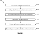
- the present invention additionally proposes a vibration and noise mapping method (100) comprising the steps of determining measurement positions (110), taking vibration and acoustic measurements (120), analyzing vibration and acoustic measurements (130), identifying excitation points (145), measuring frequency response functions (150), and generating and reporting vibration and noise maps (140).
- the steps of the determining of measurement positions (110) function are outlined below:
- the three-dimensional CAD model containing the surface that will be measured and any obstacles before it is loaded into said vibration and noise mapping system (1) in order to be processed.
- Said vibration and noise mapping system (1) optimizes and determines the measurement locations and robot positions, by taking the obstacles into account, in order to enable the measurement of the maximum surface area.
- the measurement and mapping function of said vibration and noise mapping system (1) operates according to the following basic steps.
- the laser vibrometer (vibration measurement unit (3)) within said vibration and noise mapping system (1) measures the distance (displacement) between the test object (O).
- the coordinate data of the vibration measurement sensor is recorded by the vibration and noise mapping system (1) electronic control unit according to the pre-defined reference point and reference axis. Since the displacement between the laser vibration sensor and the test object (O) is known, the position of the measurement point is calculated and this process is repeated for all measurement points.
- said measurement points are connected to generate a vibration shell model. Since the vibration shell model is generated from the data obtained from test object (O), it is compared with the CAD model and, if necessary, new measurement points are determined automatically for the missing surfaces and it is ensured that the robot starts to make measurements once more. This is continued until the shell model is completed.
- the coordinates of the end point of said noise measurement unit (4) sensor is known with reference to the coordinates of the end point of the vibration sensor.
- Noise measurement points are generated based on the known vibration measurement positions.
- an acoustic shell model is generated by connecting the measurement points.
- the features of the measurement function of vibration and noise mapping system (1) according to the present invention is explained below.
- the taking vibration and acoustic measurements (120) function is carried out as follows: The desired minimum and maximum frequency values for measurements are selected and at the same time, the frequency resolution of the measurement is selected.
- the number of measurements that will be used to get an average according to the quality of the measurements and the number of measurements that will be taken at each measurement point are determined.
- the total measurement duration is calculated by taking into account the total number of measurement points, frequency range, frequency resolution, average number and measurement conditions, and is displayed on the control unit screen.
- the measurement types and analyses that will be made may include analysis groups such as time based measurement record, octave analysis, spectrum analysis (taking Phased FFT), autopower analysis (FFT without phase information), sound intensity analysis, acoustic power analysis, and others known to the person skilled in the art.
- analysis groups such as time based measurement record, octave analysis, spectrum analysis (taking Phased FFT), autopower analysis (FFT without phase information), sound intensity analysis, acoustic power analysis, and others known to the person skilled in the art.
- the window type that will be applied to interpreting the collected data is selected separately (Windowing: Hanning, Hamming, etc.).
- the robot After the aforementioned measurement specifications are assigned, the robot goes to the positions defined for measurement and carries out the vibration and acoustic measurement at pre-defined conditions. The quality of the measurement point and the measurement is determined by checking the collected data against the average values. While test object (O) is at steady state condition dynamically (for example, operation of an internal combustion engine at constant crankshaft speed), the robot goes to the measurement locations and takes the vibration and noise measurements simultaneously. When the measurements at all locations are completed, vibration and noise mapping system (1) electronic control unit sends the "stop" command and the robot returns to the initial measurement position.
- test object (O) is at steady state condition dynamically (for example, operation of an internal combustion engine at constant crankshaft speed)
- vibration and noise mapping system (1) electronic control unit sends the "stop" command and the robot returns to the initial measurement position.
- test object (O) is operated in the next steady state condition (for example, increasing the crankshaft speed of an internal combustion engine from 1000 rpm to 1500 rpm and keeping it constant at this position) and the vibration and acoustic measurement are taken again. This is continued until the vibration and acoustic measurements at all desired conditions and all locations are completed.
- next steady state condition for example, increasing the crankshaft speed of an internal combustion engine from 1000 rpm to 1500 rpm and keeping it constant at this position
- the vibration values at all measurement conditions are examined by analyzing the shell models generated from the vibration and acoustic measurement results and the areas where vibration is concentrated are determined automatically.
- the step of analyzing the vibration and acoustic measurement (130) is described below.
- the areas where sound intensity-particle velocity-sound pressure amplitudes are highest at all conditions are determined automatically and are recorded in the memory together with the total sound intensity value at these positions. If required, the amplitudes in the areas where noise level is highest can be reduced to zero by the software or reduced to a value determined by the user and the change in total sound intensity value can be calculated.
- the vibration and noise mapping system (1) software or an external software processing the data generated from measurements taken by said vibration and noise mapping system (1) can calculate the sound pressure values at the free field microphones placed a predetermined distance away from said test object (O), using the sound power values at the measurement positions.
- the software can also calculate the sound intensity values at the free field microphones positioned virtually at a predetermined distance, by using the total sound power value calculated when the amplitudes at the areas with the highest noise level are reduced to zero.
- the software prepares the vibration and noise map report for the test object (O) automatically.
- the vibration and noise maps generation and reporting (140) function is described below:
- the vibration amplitudes at a certain frequency and vectorial vibration orientations in at least one direction positioned on the vibration shell model are calculated and drawn for each measurement point using the automatic reporting feature.
- sound intensity-particle velocity-sound pressure amplitudes in at least one direction at a certain frequency and the vectorial acoustic orientations positioned on the acoustic shell model for each measurement point are calculated and drawn.
- the vibration and noise maps for the test object (O) are generated automatically or manually, reported and sent to the related parties in a pre-determined format (for example, by e-mail) optionally, together with all the aforementioned results.
- a contactless acoustic excitation unit is integrated in addition to the available units, on at least one moving arm or Cartesian movement mechanism (2), which can move in different axes and directions at desired speeds, and thus the vibration and noise mapping system (1) of the present invention is capable of also measuring the frequency response functions of the test object (O).
- the measurements of the frequency response functions (150) are taken as follows:
- the areas on the test object (O) where high vibration and high noise amplitudes are formed simultaneously are determined by the electronic control unit of vibration and noise mapping system (1).
- the optimum excitation points are identified (145) based on the vibration amplitudes at the determined areas and communicated to the robot.
- the frequency range where measurements are required to be taken and the frequency resolution of the measurements are determined.
- the average number taken during vibration measurements is also used here.
- the robot After the necessary measurement period is calculated for the desired frequency range and measurement resolution, the robot goes to the determined positions and stimulates the structure in these areas with the acoustic excitation unit in a contactless manner. Said vibration measurement unit (3) and said noise measurement unit (4) collect data simultaneously. The "frequency response functions" are calculated following measurement. The measurements are taken until data is collected from all excitation points. After the measurement taking is complete, the obtained frequency response functions are analyzed and the natural frequencies are calculated for the structure and mode shapes are drawn.
- a geometric scanner unit is integrated on the at least one moving arm or Cartesian movement mechanism (2) that can move on different axes and directions, at desired speeds, in addition to the available units (vibration measurement unit (3) and noise measurement unit (4)), and the system is capable of scanning the surfaces of test object (O) that will be measured and generating the three-dimensional vibration shell model automatically.
- an acoustic excitation unit may also be integrated optionally, according to the embodiment described above.
- an alternative method is developed for determining the measurement points (110) step of the method by adding at least one visual element (illuminated panel, illuminated sphere, etc.) that allows for the position of the movement mechanism (2) in at least one dimension to be tracked by an external camera.
- at least one visual element illuminationted panel, illuminated sphere, etc.
- At least one camera is positioned across the measurement surface so that the complete surface can be monitored.
- the camera takes a photograph of the measurement surface.
- the simple Cartesian movement mechanism is positioned.
- a "visual object" is placed on the vibration sensor. This object may be a LED bulb, an infrared light provider, an illuminated panel, an illuminated sphere, etc.
- the sensors are moved to the appropriate positions using the simple Cartesian movement mechanism.
- the command to go into the measurement position is given to the system, the image is processed and the position of the illuminated visual object is determined by the camera and is recorded to the memory as the measurement point on the first photograph. This is repeated for all measurement points and a vibration shell model is generated by connecting the measurement points.
- the coordinates of the noise measurement sensor end point is known with reference to the coordinates of the vibration sensor end point. Noise measurement points are generated based on the known vibration measurement positions.
- An acoustic shell model is generated by connecting the measurement points.
- the present invention is related to at least one vibration measurement sensor (3) adapted to measure the vibrations formed on a test object (O) with moving mechanical systems, at least one noise measurement sensor (4) adapted to measure sound intensity, particle velocity, sound pressure in at least one direction, i.e. on one axis, and a vibration and noise mapping system (1) that is adapted to control the vibration measurement sensor (3) and the noise measurement sensor (4), to provide the vibration and acoustic performance data of the test object (O) according to the data obtained from these units (3, 4) and to identify the areas on the test object (O) that are problematic or required to be studied further in order to improve the vibration and acoustic performance, and to control the operation of test objects (O) such as moving mechanical systems under different conditions.
- a vibration measurement sensor (3) adapted to measure the vibrations formed on a test object (O) with moving mechanical systems
- at least one noise measurement sensor (4) adapted to measure sound intensity, particle velocity, sound pressure in at least one direction, i.e. on one axis
- the electronic control unit of said vibration and noise mapping system (1) is electrically connected to at least one internal data processing unit (5), and said data processing unit (5) may also be realized as an external unit.
- the data processing unit (5) is a separate hardware that has a high processor power and is suitable to carry out sophisticated data processing functions, and operates as connected with the electronic control unit.
- the data processor unit (5) may process the raw data according to the measurement results, as an external hardware.
- the present invention proposes a vibration and noise mapping system (1) for the generation of vibration and noise maps of vibration and noise sources and rapid identification of areas, which are desired to be improved and/or are problematic, comprising at least one movement mechanism (2) that is movable on different axes and directions at desired speeds, at least one vibration measurement unit (2) that is movable together with said movement mechanism (2), and is adapted to measure the vibration of a test object (O) in at least one direction, and at least one noise measurement unit (4) that is movable together with said movement mechanism (2) and is adapted to measure sound intensity and/or particle velocity and/or sound pressure in at least one direction on said test object (O).
- said vibration and noise mapping system (1) comprises an electronic control unit whereby the control of said vibration and noise mapping system (1) in order to match at least one vibration data measured by said vibration unit (3) at a location to at least one noise data measured by said noise measurement unit (4) at the same location and collect matching vibration and noise data corresponding to multiple locations is facilitated.
- said vibration and noise mapping system (1) comprises at least one contactless acoustic excitation unit that is movable together with said movement mechanism (2) for ensuring that preferred points on the test object (O) are excited without contact.
- said vibration and noise mapping system (1) comprises an electronic control unit whereby the measurement of the distance between said vibration measurement unit (3) and said test object (O) prior to each vibration measurement for each location, and recording of coordinate data of said vibration measurement unit (3) based on a predetermined reference point and a reference axis is facilitated.
- said vibration and noise mapping system (1) comprises an electronic control unit whereby the generation of a vibration shell model by connecting coordinates of vibration measurements taken by said vibration measurement unit (3) is facilitated.
- said vibration and noise mapping system (1) comprises an electronic control unit whereby the comparison of the generated vibration shell model against a computer-aided design model of said test object (O) in order to determine new measurement points for missing surfaces and taking vibration measurements thereon is facilitated.
- said vibration and noise mapping system (1) comprises an electronic control unit whereby the calculation of the measurement coordinates of the noise measurement unit (4) based on the measurement coordinates of the vibration measurement unit (3) and the generation of an acoustic shell model by connecting said measurement points are facilitated.
- said vibration and noise mapping system (1) comprises a vibration measurement unit (3) and noise measurement unit (4) whereby taking of measurements of said test object (O) in more than one dynamic steady state condition is facilitated.
- said vibration and noise mapping system (1) comprises a vibration measurement unit (3) adapted to make frequency response function measurements for said test object (O).
- said vibration and noise mapping system (1) comprises an electronic control unit whereby the calculation of the vibration amplitudes at certain frequency and vectorial vibration orientations in at least one direction for each measurement point positioned on the vibration shell model, and/or sound intensity-particle velocity-sound pressure amplitudes at certain frequency and vectorial acoustic orientations in at least one direction for each measurement point positioned on the acoustic shell model is facilitated.
- said vibration and noise mapping system (1) comprises a contactless acoustic excitation unit whereby the acoustic and contactless excitation of the excitation points, which are determined based on the vibration amplitudes in the areas where high vibration and high noise amplitudes are formed simultaneously on said test object (O), is facilitated.
- said vibration and noise mapping system (1) comprises at least one visual element for ensuring that the position of said movement mechanism (2) is tracked in at least one direction and an external camera for tracking said visual element.
- said visual element is a light source.
- said vibration and noise mapping system (1) comprises a camera for ensuring that the position of said visual element is determined based on the image detected by said camera, through image processing of the photograph of the measurement surface taken by said camera, which is placed across the measurement surface in a way to see the complete surface, and visual element placed in front of the said vibration measurement unit (3).
- said vibration and noise mapping system (1) comprises a memory whereby recording of said position of said visual element, which is determined by image processing, as a measurement point on the first photograph is facilitated.
- said vibration and noise mapping system (1) comprises an electronic control unit that has been adapted to control the operation of movement mechanism (2), vibration measurement unit (3), noise measurement unit (4) and acoustic excitation unit.
- said vibration and noise mapping system (1) comprises an electronic control unit whereby moving of the movement mechanism (2) in a certain direction and axis, close to or away from said test object (O) and certain parts of said test object (O) during the test process is facilitated.
- said vibration and noise mapping system (1) comprises an electronic control unit adapted to operate said noise measurement unit (4) for sound intensity, sound pressure and particle velocity measurement in order to start the measurements and take said noise measurement unit (4) to the new preferred position by operating said movement mechanism (2) according to the measurement values.
- said vibration and noise mapping system (1) comprises an electronic control unit adapted to consecutively operate said vibration measurement unit (3) and said noise measurement unit (4) and control acoustic excitation unit to take frequency response function measurements for said test object (O).
- said at least one dimensional vibration measurement unit (3) is a laser vibration measurement unit (3) and said noise measurement unit (4) is a sound intensity, particle velocity and sound pressure measurement unit.
- present invention proposes a vibration and noise mapping method (100) for the generation of vibration and noise maps of vibration and noise sources and rapid identification of areas, which are desired to be improved and/or are problematic using a vibration and noise mapping system (1) according to any preceding Claim, comprising the steps of:
- said determining measurement positions (110) step further comprises the steps of optimizing the vibration measurement locations by taking the obstacles into account and determining the positions where measurements will be made by an electronic control unit, as per initial data set, so as to enable the measurement of a maximum surface area on a test object (O).
- said determining measurement positions (110) step further comprises the step of electronic control unit comparing the vibration shell model with the three-dimensional computer-aided design model that is loaded externally and determining new measurement points for the missing surfaces, and taking measurements again by operating movement mechanism (2).
- said determining measurement positions (110) step further comprises the step of electronic control unit moving the movement mechanism (2) to the points to be measured one by one and recording the position data in the memory of said electronic control unit.
- said taking vibration and acoustic measurements (120) step further comprises the steps of movement mechanism (2) moving to the measurement locations, vibration measurement unit (3) taking vibration measurements and noise measurement unit (4) taking acoustic measurements.
- said analyzing the vibration and acoustic measurements (130) step further comprises the step of the electronic control unit determining the areas where there is intensive vibration by analyzing the vibration and acoustic measurement results and the vibration values of the shell models at all pre-defined, different measurement conditions.
- said analyzing the vibration and acoustic measurements (130) step further comprises the steps of the electronic control unit analyzing of the areas where sound intensity, particle velocity and sound pressure amplitudes in at least one direction are the highest in all pre-defined measurement conditions and recording together with the total sound power value in that condition.
- said analyzing the vibration and acoustic measurements (130) step further comprises the steps of the electronic control unit reducing of the amplitudes to zero at areas where the highest level of noise is created and calculating the change in total sound power value.
- said analyzing the vibration and acoustic measurements (130) step further comprises the step of the electronic control unit calculating the sound pressure values on the free-field microphones that are virtually positioned at a certain distance to the test object (O) using of the sound power values at the measurement points.
- said identifying the excitation points (145) step further comprises the steps of the electronic control unit determining the areas where high vibration and noise amplitudes are formed simultaneously on the test object (O) and a contactless acoustic excitation unit exciting said areas in a contactless manner.
- said measuring the frequency response functions (150) further comprises the step of vibration measurement unit (3) taking measurements in the areas that are excited by a contactless acoustic excitation unit, measuring the frequency response functions.
- said measuring the frequency response functions (150) further comprises the step of electronic control unit analyzing the obtained frequency response functions, calculating the natural frequencies for the test object (O), and drawing the mode shapes.
- said generating and reporting vibration and noise maps (140) step further comprises the step of electronic control unit generating the mode shapes of said test object (O).
- said generating and reporting vibration and noise maps (140) step further comprises the steps of electronic control unit analyzing the test data, calculating and drawing the vibration amplitudes in the frequency range where measurements have been made and the vectorial vibration orientations in at least one direction on the vibration shell model for each measurement point.
- said generating and reporting vibration and noise maps (140) step further comprises the steps of electronic control unit analyzing the test data, and calculating and drawing the sound intensity, particle velocity, sound pressure amplitudes in at least one direction in the frequency range where measurements have been made and the vectorial acoustic orientations in at least one direction positioned on the acoustic shell model for each measurement point.
- said generating and reporting vibration and noise maps (140) step further comprises the step of electronic control unit drawing the vibration and acoustic orientations positioned for each measurement point on the shell models and the amplitudes thereof concurrently or separately.
Landscapes
- Physics & Mathematics (AREA)
- Engineering & Computer Science (AREA)
- General Physics & Mathematics (AREA)
- Theoretical Computer Science (AREA)
- Mathematical Physics (AREA)
- Acoustics & Sound (AREA)
- General Engineering & Computer Science (AREA)
- Radar, Positioning & Navigation (AREA)
- Remote Sensing (AREA)
- Data Mining & Analysis (AREA)
- Computational Mathematics (AREA)
- Mathematical Analysis (AREA)
- Databases & Information Systems (AREA)
- Pure & Applied Mathematics (AREA)
- Software Systems (AREA)
- Mathematical Optimization (AREA)
- Chemical & Material Sciences (AREA)
- Combustion & Propulsion (AREA)
- Quality & Reliability (AREA)
- Computer Vision & Pattern Recognition (AREA)
- Computing Systems (AREA)
- Computer Hardware Design (AREA)
- Automation & Control Theory (AREA)
- Algebra (AREA)
- Measurement Of Mechanical Vibrations Or Ultrasonic Waves (AREA)
Claims (35)
- Schwingungs- und Lärmkartierungssystem (1) zur Erstellung von Schwingungs- und Lärmkarten von Schwingungs- und Lärmquellen und zur schnellen Erkennung von Bereichen, die verbessert werden sollen und/oder problematisch sind, umfassendmindestens einen Bewegungsmechanismus (2), der einzeln betätigt werden kann, um sich in verschiedenen Achsen und Richtungen mit gewünschten Geschwindigkeiten zu bewegen,mindestens eine Sichwingungsmesseinheit (3), die zusammen mit dem genannten Bewegungsmechanismus (2) beweglich ist und dazu eingerichtet ist, die Schwingung eines Prüfgegenstands (O) in mindestens einer Richtung zu messen, und,mindestens eine Lärmmesseinheit (4), die zusammen mit dem genannten Bewegungsmechanismus (2) beweglich ist und dazu eingerichtet ist, die Schallintensität und/oder die Partikelgeschwindigkeit und/oder den Schalldruck in mindestens einer Richtung an dem genannten Prüfgegenstand (O) zu messen,dadurch gekennzeichnet, dassdas genannte Schwingungs- und Lärmkartierungssystem (1) eine elektronische Steuereinheit umfasst, die dazu eingerichtet ist, das Schwingungs- und Lärmkartierungssystem (1) zu steuern, um mindestens ein von der Schwingungssmesseinheit (3) an einem Ort gemessener Schwingungswert zu mindestens einem von der Lärmmesseinheit (4) an demselben Ort gemessenen Lärmwert zuzuordnen und zusammengehörige Schwingungs- und Lärmdaten zu sammeln, die mehreren Orten entsprechen,wobei die genannte mindestens eine Schwingungsmesseinheit (3) und die genannte mindestens eine Lärmmesseinheit (4) in den genannten Bewegungsmechanismus (2) integriert sind unddas Schwingungs- und Lärmkartierungssystem (1) dazu konfiguriert ist, vor Beginn der Datenerfassung Daten über die entsprechenden Messpositionen zu empfangen.
- Schwingungs- und Lärmkartierungssystem (1) nach Anspruch 1, dadurch gekennzeichnet, dass das genannte Schwingungs- und Lärmkartierungssystem (1) mindestens eine berührungslose akustische Anregungseinheit umfasst, die zusammen mit dem genannten Bewegungsmechanismus (2) beweglich ist, um sicherzustellen, dass bevorzugte Stelle auf dem Prüfgegenstand (O) berührungslos angeregt werden.
- Schwingungs- und Lärmkartierungssystem (1) nach Anspruch 1 oder 2, dadurch gekennzeichnet, dass das Schwingungs- und Lärmkartierungssystem (1) eine elektronische Steuereinheit umfasst, die dazu eingerichtet ist, vor jeder Schwingungsmessung für den jeweiligen Ort den Abstand zwischen der genannten Schwingungsmesseinheit (3) und dem Prüfgegenstand (O) zu messen und die Koordinatendaten der genannten Schwingungsmesseinheit (3) anhand eines vorbestimmten Referenzpunkts und einer Referenzachse aufzuzeichnen.
- Schwingungs- und Lärmkartierungssystem (1) nach Anspruch 3, dadurch gekennzeichnet, dass das Schwingungs- und Lärmkartierungssystem (1) eine elektronische Steuereinheit umfasst, die dazu eingerichtet ist, durch Verbinden der Koordinaten von Schwingungsmessungen, die von der Schwingungsmesseinheit (3) durchgeführt wurden, ein Schwingungsschalenmodell zu erstellen.
- Schwingungs- und Lärmkartierungssystem (1) nach Anspruch 4, dadurch gekennzeichnet, dass das Schwingungs- und Lärmkartierungssystem (1) eine elektronische Steuereinheit umfasst, die dazu eingerichtet ist, das erstellte Schwingungsschalenmodell mit einem computergestützten Konstruktionsmodell des genannten Prüfgegenstands (O) zu vergleichen, um neue Messpunkte für fehlende Oberflächen zu bestimmen und darauf Schwingungsmessungen durchzuführen.
- Schwingungs- und Lärmkartierungssystem (1) nach Anspruch 5, dadurch gekennzeichnet, dass das genannte Schwingungs- und Lärmkartierungssystem (1) eine elektronische Steuereinheit umfasst, wodurch die Berechnung von Messkoordinaten der Lärmmesseinheit (4) anhand der Messkoordinaten der Schwingungsmesseinheit (3) und die Erstellung eines akustischen Schalenmodells durch Verbinden der Messpunkte erleichtert wird.
- Schwingungs- und Lärmkartierungssystem (1) nach Anspruch 1, dadurch gekennzeichnet, dass das Schwingungs- und Lärmkartierungssystem (1) eine Schwingungsmesseinheit (3) und eine Lärmmesseinheit (4) umfasst, die dazu eingerichtet sind, Messungen an dem genannten Prüfgegenstands (O) in mehr als einem dynamischen stationären Zustand durchzuführen.
- Schwingungs- und Lärmkartierungssystem (1) nach Anspruch 1, dadurch gekennzeichnet, dass das genannte Schwingungs- und Lärmkartierungssystem (1) eine Schwingungsmesseinheit (3) umfasst, die dazu eingerichtet ist, Frequenzgangfunktionsmessungen für das Prüfgegenstand (O) durchzuführen.
- Schwingungs- und Lärmkartierungssystem (1) nach Anspruch 6, dadurch gekennzeichnet, dass das genannte Schwingungs- und Lärmkartierungssystem (1) eine elektronische Steuereinheit umfasst, die dazu eingerichtet ist, die Schwingungsamplituden bei bestimmten Frequenzen und vektoriellen Schwingungsausrichtungen in mindestens einer Richtung für jeden auf dem Schwingungsschalenmodell positionierten Messpunkt und/oder Schallintensitäts-, Partikelgeschwindigkeits- und Schalldruckamplituden bei bestimmten Frequenzen und vektoriellen akustischen Ausrichtungen in mindestens einer Richtung für jeden auf dem Akustikschalenmodell positionierten Messpunkt zu berechnen.
- Schwingungs- und Lärmkartierungssystem (1) nach Anspruch 2, dadurch gekennzeichnet, dass das Schwingungs- und Lärmkartierungssystem (1) eine berührungslose akustische Anregungseinheit umfasst, die dazu eingerichtet ist, die Anregungspunkte, die anhand der Schwingungsamplituden in den Bereichen bestimmt werden, in denen gleichzeitig hohe Schwingungs- und Geräuschamplituden am Prüfgegenstand (O) auftreten, auf akustische und berührungslose Weise anzuregen.
- Schwingungs- und Lärmkartierungssystem (1) nach Anspruch 1, dadurch gekennzeichnet, dass das genannte Schwingungs- und Lärmkartierungssystem (1) mindestens ein vor der Schwingungsmesseinheit (3) positioniertes, visuelles Element umfasst, um sicherzustellen, dass die Position des genannten Bewegungsmechanismus (2) in mindestens eine Richtung überwacht wird, und eine externe Kamera zur Überwachung des genannten visuellen Elements umfasst.
- Schwingungs- und Lärmkartierungssystem (1) nach Anspruch 11, dadurch gekennzeichnet, dass das genannte visuelle Element eine Lichtquelle ist.
- Schwingungs- und Lärmkartierungssystem (1) nach Anspruch 11 oder 12, dadurch gekennzeichnet, dass das genannte Schwingungs- und Lärmkartierungssystem (1) eine Kamera umfasst, um sicherzustellen, dass die Position des visuellen Elements anhand des von der genannten Kamera erfassten Bildes und zwar durch Bildverarbeitung des von der Kamera aufgenommenen Bildes der Messoberfläche bestimmt wird, wobei die Kamera derart über der Messoberfläche positioniert ist, dass die gesamte Oberfläche sichtbar ist, und ein visuelles Element, das vor der Schwingungsmesseinheit (3) angeordnet ist, umfasst.
- Schwingungs- und Lärmkartierungssystem (1) nach Anspruch 13, dadurch gekennzeichnet, dass das genannte Schwingungs- und Lärmkartierungssystem (1) einen Speicher umfasst, der dazu eingerichtet ist, die Position des genannten visuellen Elements, die durch Bildverarbeitung bestimmt wird, als Messpunkt auf dem ersten Bild zu speichern.
- Schwingungs- und Lärmkartierungssystem (1) nach Anspruch 2, dadurch gekennzeichnet, dass das genannte Schwingungs- und Lärmkartierungssystem (1) eine elektronische Steuereinheit umfasst, die dazu eingerichtet ist, den Betrieb des Bewegungsmechanismus (2), der Schwingungsmesseinheit (3), der Lärmmesseinheit (4) und der akustischen Anregungseinheit zu steuern.
- Schwingungs- und Lärmkartierungssystem (1) nach Anspruch 1, dadurch gekennzeichnet, dass das genannte Schwingungs- und Lärmkartierungssystem (1) eine elektronische Steuereinheit umfasst, die dazu eingerichtet ist, den Bewegungsmechanismus (2) während des Prüfvorgangs in eine bestimmte Richtung und Achse nahe an oder weg vom Prüfgegenstand (O) und von bestimmten Teilen des genannten Prüfgegenstands (O) zu bewegen.
- Schwingungs- und Lärmkartierungssystem (1) nach Anspruch 1, dadurch gekennzeichnet, dass das genannte Schwingungs- und Lärmkartierungssystem (1) eine elektronische Steuereinheit umfasst, die dazu eingerichtet ist, die Lärmmesseinheit (4) zur Messung von Schallintensität, Schalldruck und Partikelgeschwindigkeit zu betätigen, um die Messungen zu starten und die Lärmmesseinheit (4) durch Betätigen des Bewegungsmechanismus (2) entsprechend den Messwerten in die neue bevorzugte Position zu bringen.
- Schwingungs- und Lärmkartierungssystem (1) nach Anspruch 2, dadurch gekennzeichnet, dass das genannte Schwingungs- und Lärmkartierungssystem (1) eine elektronische Steuereinheit umfasst, die dazu eingerichtet ist, nacheinander die genannte Schwingungsmesseinheit (3), die dazu ausgebildet ist, Frequenzgangfunktionsmessungen für das genannte Prüfgegenstand (O) durchzuführen, und die genannte Lärmmesseinheit (4) zu betätigen und die akustische Anregungseinheit zu steuern und Frequenzgangfunktionsmessungen für das genannte Prüfgegenstand (O) durchzuführen.
- Schwingungs- und Lärmkartierungssystem (1) nach Anspruch 1, dadurch gekennzeichnet, dass die genannte, mindestens eindimensionale Schwingungsmesseinheit (3) eine Laserschwingungsmesseinheit (3) ist und die genannte Lärmmesseinheit (4) eine Schallintensitäts-, Partikelgeschwindigkeits- und Schalldruckmesseinheit ist.
- Schwingungs- und Lärmkartierungsverfahren (100) zum Erstellen von Schwingungs- und Lärmkarten von Schwingungs- und Lärmquellen und zur schnellen Erkennung von Bereichen, die verbessert werden sollen und/oder problematisch sind, unter Verwendung eines Schwingungs- und Lärmkartierungssystems (1) gemäß einem der vorangehenden Ansprüche, umfassend mindestens eine Schwingungsmesseinheit (3) und mindestens eine Lärmmesseinheit (4), die beide in einen Bewegungsmechanismus (2) integriert sind, und wobei das Verfahren (100) folgende Schritte umfasst:- Bestimmen von Messpositionen (110),- Durchführen von Schwingungs- und Schallmessungen (120),- Analysieren von Schwingungs- und Schallmessungen (130),- Erkennen von Anregungspunkten (145),- Messen von Frequenzgangfunktionen (150) und- Erstellen und Berichten von Schwingungs- und Lärmkarten (140).
- Schwingungs- und Lärmkartierungsverfahren (100) nach Anspruch 20, dadurch gekennzeichnet, dass der genannte Schritt des Bestimmens der Messpositionen (110) ferner die Schritte umfasst, worin die Schwingungsmessstellen durch Berücksichtigung von Hindernissen optimiert wird und die Positionen, an denen Messungen durchzuführen sind, durch eine elektronische Steuereinheit gemäß einem Anfangsdatensatz bestimmt wird, wobei es sich bei dem Anfangsdatensatz um ein dreidimensionales computergestütztes Konstruktionsmodell handelt, das die zu messende Oberfläche und etwaige Hindernisse beinhaltet, bevor es in das Schwingungs- und Lärmkartierungssystem (1) geladen wird, derart dass die Messung einer maximalen Oberfläche auf einem Prüfgegenstands (O) ermöglicht wird.
- Schwingungs- und Lärmkartierungsverfahren (100) nach Anspruch 21, dadurch gekennzeichnet, dass der genannte Schritt des Bestimmens der Messpositionen (110) ferner den Schritt umfasst, worin die elektronische Steuereinheit das Schwingungsschalenmodell, das durch Verbinden von Koordinaten der von der Schwingungsmesseinheit (3) durchgeführten Schwingungsmessungen erstellt wurde, mit dem extern geladenen dreidimensionalen computergestützten Konstruktionsmodell vergleicht und neue Messpunkte für die fehlenden Oberflächen bestimmt und durch Betätigen des Bewegungsmechanismus (2) erneut Messungen durchführt.
- Schwingungs- und Lärmkartierungsverfahren (100) nach Anspruch 21, dadurch gekennzeichnet, dass der genannte Schritt des Bestimmens der Messpositionen (110) ferner den Schritt umfasst, worin die elektronische Steuereinheit den Bewegungsmechanismus (2) nacheinander zu den zu messenden Punkten bewegt und die jeweilige Positionsdaten im Speicher der elektronischen Steuereinheit speichert.
- Schwingungs- und Lärmkartierungsverfahren (100) nach Anspruch 20, dadurch gekennzeichnet, dass der genannte Schritt des Durchführens der Schwingungs- und Schallmessungen (120) ferner die Schritte umfasst, worin jeweils der Bewegungsmechanismus (2) sich zu den Messstellen bewegt, die Schwingungsmesseinheit (3) Schwingungsmessungen durchführt und anschließend die Lärmmesseinheit (4) Schallmessungen durchführt.
- Schwingungs- und Lärmkartierungsverfahren (100) nach Anspruch 22, dadurch gekennzeichnet, dass der genannte Schritt des Analysierens von Schwingungs- und Schallmessungen (130) ferner den Schritt umfasst, worin die elektronische Steuereinheit die Bereiche mit intensiver Schwingung durch Analysieren von Schwingungs- und Schallmessergebnisse und Schwingungswerte der Schalenmodelle unter allen vordefinierten, unterschiedlichen Messbedingungen bestimmt.
- Schwingungs- und Lärmkartierungsverfahren (100) nach Anspruch 20, dadurch gekennzeichnet, dass der genannte Schritt des Analysierens von Schwingungs- und Schallmessungen (130) ferner den Schritt umfasst, worin die elektronische Steuereinheit die Bereiche analysiert, in denen die Schallintensität, die Partikelgeschwindigkeit und die Schalldruckamplituden in mindestens einer Richtung unter allen vordefinierten Messbedingungen am höchsten sind, und diese zusammen mit dem Gesamtschallleistungswert unter jeweiligen Bedingungen speichert.
- Schwingungs- und Lärmkartierungsverfahren (100) nach Anspruch 20, dadurch gekennzeichnet, dass der genannte Schritt des Analysierens von Schwingungs- und Schallmessungen (130) ferner die Schritte umfasst, worin die elektronische Steuereinheit die Amplituden in Bereichen, in denen der höchste Lärmpegel entsteht, auf Null oder auf einen bestimmten Pegel reduziert und die Änderung des Gesamtschallleistungswerts berechnet.
- Schwingungs- und Lärmkartierungsverfahren (100) nach Anspruch 20, dadurch gekennzeichnet, dass der genannte Schritt des Analysierens von Schwingungs- und Schallmessungen (130) ferner den Schritt umfasst, worin die elektronische Steuereinheit die Schalldruckwerte an den Freifeldmikrofonen, die virtuell in einer bestimmten Entfernung zum Prüfgegenstand (O) positioniert sind, unter Verwendung der Schallleistungswerte an den Messpunkten berechnet.
- Schwingungs- und Lärmkartierungsverfahren (100) nach Anspruch 20, dadurch gekennzeichnet, dass der genannte Schritt des Erkennens von Anregungspunkte (145) ferner die Schritte umfasst, worin die elektronische Steuereinheit die Bereiche bestimmt, in denen gleichzeitig hohe Schwingungs- und Lärmamplituden am Prüfgegenstand (O) entstehen, und eine berührungslose akustische Anregungseinheit diese Bereiche auf berührungslose Weise anregt.
- Schwingungs- und Lärmkartierungsverfahren (100) nach Anspruch 20, dadurch gekennzeichnet, dass der genannte Schritt des Messens von Frequenzgangfunktionen (150) ferner den Schritt umfasst, worin die Schwingungsmesseinheit (3) Messungen in den Bereichen durchführt, die durch eine berührungslose akustische Anregungseinheit angeregt werden, und die Frequenzgangfunktionen misst.
- Schwingungs- und Lärmkartierungsverfahren (100) nach Anspruch 30, dadurch gekennzeichnet, dass der genannte Schritt des Messens von Frequenzgangfunktionen (150) ferner den Schritt umfasst, worin die elektronische Steuereinheit die erhaltenen Frequenzgangfunktionen analysiert, die Eigenfrequenzen für das Prüfgegenstand (O) berechnet und die Schwingungsformen zeichnet.
- Schwingungs- und Lärmkartierungsverfahren (100) nach Anspruch 31, dadurch gekennzeichnet, dass der genannte Schritt des Erstellens und Berichtens von Schwingungs- und Lärmkarten (140) ferner den Schritt umfasst, worin die elektronische Steuereinheit die Schwingungsformen des Prüfgegenstands (O) erstellt.
- Schwingungs- und Lärmkartierungsverfahren (100) nach Anspruch 32, dadurch gekennzeichnet, dass der genannte Schritt des Erstellens und Berichtens von Schwingungs- und Lärmkarten (140) ferner die Schritte umfasst, worin die elektronische Steuereinheit die Prüfdaten analysiert, die Schwingungsamplituden in dem Frequenzbereich, in dem Messungen durchgeführt wurden, und die vektoriellen Schwingungsausrichtungen in mindestens einer Richtung auf dem Schwingungsschalenmodell für jeden Messpunkt berechnet und zeichnet.
- Schwingungs- und Lärmkartierungsverfahren (100) nach Anspruch 32, dadurch gekennzeichnet, dass der genannte Schritt des Erstellens und Berichtens von Schwingungs- und Lärmkarten (140) ferner die Schritte umfasst, worin die elektronische Steuereinheit die Prüfdaten analysiert und die Schallintensitäts, Partikelgeschwindigkeit, Schalldruckamplituden in mindestens einer Richtung in dem Frequenzbereich, in dem Messungen durchgeführt wurden, und die vektoriellen akustischen Ausrichtungen in mindestens einer Richtung, die auf dem akustischen Schalenmodell für jeden Messpunkt positioniert ist, berechnet und zeichnet.
- Schwingungs- und Lärmkartierungsverfahren (100) nach Anspruch 32, dadurch gekennzeichnet, dass der genannte Schritt des Erstellens und Berichtens von Schwingungs- und Lärmkarten (140) ferner den Schritt umfasst, worin die elektronische Steuereinheit die für jeden Messpunkt auf den Schalenmodellen positionierten Schwingungs- und Schallausrichtungen und deren Amplituden gleichzeitig oder separat zeichnet.
Applications Claiming Priority (2)
| Application Number | Priority Date | Filing Date | Title |
|---|---|---|---|
| TR2016/20208A TR201620208A1 (tr) | 2016-12-30 | 2016-12-30 | Kompakt ti̇treşi̇m ve gürültü hari̇talandirma si̇stemi̇ ve yöntemi̇ |
| PCT/TR2017/050708 WO2018125017A1 (en) | 2016-12-30 | 2017-12-27 | A compact system and method for vibration and noise mapping |
Publications (2)
| Publication Number | Publication Date |
|---|---|
| EP3563136A1 EP3563136A1 (de) | 2019-11-06 |
| EP3563136B1 true EP3563136B1 (de) | 2025-01-01 |
Family
ID=61188881
Family Applications (1)
| Application Number | Title | Priority Date | Filing Date |
|---|---|---|---|
| EP17840508.0A Active EP3563136B1 (de) | 2016-12-30 | 2017-12-27 | Kompaktsystem und -verfahren zur schwingungs- und rauschabbildung |
Country Status (5)
| Country | Link |
|---|---|
| US (1) | US11480461B2 (de) |
| EP (1) | EP3563136B1 (de) |
| CN (1) | CN110325835B (de) |
| TR (1) | TR201620208A1 (de) |
| WO (1) | WO2018125017A1 (de) |
Families Citing this family (15)
| Publication number | Priority date | Publication date | Assignee | Title |
|---|---|---|---|---|
| WO2019187834A1 (ja) | 2018-03-30 | 2019-10-03 | ソニー株式会社 | 情報処理装置、情報処理方法、およびプログラム |
| WO2020008755A1 (ja) * | 2018-07-06 | 2020-01-09 | ソニー株式会社 | 情報処理装置、情報処理システム、行動計画方法及びプログラム |
| CN109084891B (zh) * | 2018-10-25 | 2023-07-21 | 赛腾机电科技(常州)有限公司 | 一种基于受力变化的旋转体噪声测试系统 |
| JP7268419B2 (ja) * | 2019-03-15 | 2023-05-08 | オムロン株式会社 | パラメータ設定支援装置、パラメータ設定支援方法及びパラメータ設定支援プログラム |
| CN109900349A (zh) * | 2019-03-15 | 2019-06-18 | 中科新悦(苏州)科技有限公司 | 一种声学振动传感器集成测试套件及其测试方法 |
| JP7347506B2 (ja) * | 2019-06-06 | 2023-09-20 | 日本電信電話株式会社 | 集音装置、到来方向推定装置、振動情報収集装置 |
| CN110617876B (zh) * | 2019-11-01 | 2021-10-22 | 云南电网有限责任公司电力科学研究院 | 电力设备异响定位方法 |
| CN112414541A (zh) * | 2020-11-09 | 2021-02-26 | 东风汽车集团有限公司 | 一种自动化车外噪声测试装置和噪声测试方法 |
| JP7444045B2 (ja) * | 2020-12-17 | 2024-03-06 | トヨタ自動車株式会社 | 音源探査システムおよび音源探査方法 |
| CN114136435B (zh) * | 2021-11-18 | 2023-07-04 | 大连交通大学 | 一种无线便携展开式轨道车辆结构噪声测量系统及方法 |
| CN115047080B (zh) * | 2022-05-06 | 2025-03-21 | 国网山西省电力公司电力科学研究院 | 声学成像仪准确性测试方法及其装置 |
| JP7802637B2 (ja) * | 2022-09-13 | 2026-01-20 | 株式会社東芝 | 振動可視化システム、振動可視化方法 |
| CN115468646A (zh) * | 2022-09-14 | 2022-12-13 | 深圳北芯医疗科技有限公司 | 冲击波声压测量方法、设备、系统和计算机可读存储介质 |
| US12607541B2 (en) * | 2023-02-03 | 2026-04-21 | Hitachi, Ltd. | Robust predictive maintenance method for machinery using measured vibration data and estimated sound data |
| CN116147755A (zh) * | 2023-03-31 | 2023-05-23 | 电子科技大学 | 一种基于激光测振的磁共振成像设备工作噪声的声压级计算方法 |
Citations (3)
| Publication number | Priority date | Publication date | Assignee | Title |
|---|---|---|---|---|
| FR2867563A1 (fr) * | 2004-03-11 | 2005-09-16 | Marmonier | Procede dynamique de caracterisation audio des bruits rayonnes par une structure vibrante et de differentiation des bruits solidiens dans un bruit complexe global |
| DE102007023826A1 (de) * | 2007-05-21 | 2008-11-27 | Polytec Gmbh | Verfahren und Vorrichtung zur berührungslosen Schwingungsmessung |
| US8483977B1 (en) * | 2010-06-04 | 2013-07-09 | The United States Of America As Represented By The Secretary Of The Navy | Method of laser vibration defect analysis |
Family Cites Families (14)
| Publication number | Priority date | Publication date | Assignee | Title |
|---|---|---|---|---|
| NL1008006C1 (nl) | 1998-01-09 | 1999-07-12 | Microflown Technologies B V | Deeltjessnelheidssensor. |
| EP1431740B1 (de) | 2002-12-16 | 2006-03-08 | Polytec GmbH | Messvorrichtung zum berührungslosen Erfassen von Schwingungen eines Objektes |
| WO2004090485A2 (en) * | 2003-04-03 | 2004-10-21 | Sri International | Method and apparatus for real-time vibration imaging |
| JP4852372B2 (ja) * | 2006-08-07 | 2012-01-11 | 株式会社日立製作所 | 構造最適化システム |
| US8281330B2 (en) * | 2006-10-04 | 2012-10-02 | Mitsubishi Electric Corporation | Disk apparatus |
| JP5236516B2 (ja) * | 2009-01-30 | 2013-07-17 | アイシン・エィ・ダブリュ株式会社 | 音響特性最適化モデル解析装置、音響特性最適化モデル解析方法及び音響特性最適化モデル解析プログラム |
| US8836660B2 (en) * | 2009-09-28 | 2014-09-16 | Toyota Jidosha Kabushiki Kaisha | Tactile display and CAD system |
| CN101813638B (zh) * | 2010-04-30 | 2012-06-13 | 华中科技大学 | 一种芯片焊点缺陷在线检测方法及装置 |
| US8306793B2 (en) * | 2010-06-04 | 2012-11-06 | Livermore Software Technology Corporation | Systems and methods of performing vibro-acoustic analysis of a structure |
| US8410952B2 (en) * | 2010-12-08 | 2013-04-02 | Ut-Battelle, Llc | Methods for forewarning of critical condition changes in monitoring civil structures |
| US8949085B2 (en) * | 2011-10-28 | 2015-02-03 | General Electric Company | System and method for obtaining and de-noising vibratory data |
| CN104568958B (zh) * | 2013-10-16 | 2017-08-04 | 国标(北京)检验认证有限公司 | 一种光和超声复合激励的红外无损检测装置 |
| US9709437B2 (en) * | 2015-02-18 | 2017-07-18 | City University Of Hong Kong | System and method for detecting a defect in a structure member |
| CN105334262B (zh) * | 2015-12-04 | 2017-12-19 | 东北大学 | 基于光学干涉法的非接触光声探测方法及装置 |
-
2016
- 2016-12-30 TR TR2016/20208A patent/TR201620208A1/tr unknown
-
2017
- 2017-12-27 US US16/475,142 patent/US11480461B2/en active Active
- 2017-12-27 WO PCT/TR2017/050708 patent/WO2018125017A1/en not_active Ceased
- 2017-12-27 CN CN201780087765.5A patent/CN110325835B/zh active Active
- 2017-12-27 EP EP17840508.0A patent/EP3563136B1/de active Active
Patent Citations (3)
| Publication number | Priority date | Publication date | Assignee | Title |
|---|---|---|---|---|
| FR2867563A1 (fr) * | 2004-03-11 | 2005-09-16 | Marmonier | Procede dynamique de caracterisation audio des bruits rayonnes par une structure vibrante et de differentiation des bruits solidiens dans un bruit complexe global |
| DE102007023826A1 (de) * | 2007-05-21 | 2008-11-27 | Polytec Gmbh | Verfahren und Vorrichtung zur berührungslosen Schwingungsmessung |
| US8483977B1 (en) * | 2010-06-04 | 2013-07-09 | The United States Of America As Represented By The Secretary Of The Navy | Method of laser vibration defect analysis |
Also Published As
| Publication number | Publication date |
|---|---|
| TR201620208A1 (tr) | 2018-07-23 |
| EP3563136A1 (de) | 2019-11-06 |
| US20190331522A1 (en) | 2019-10-31 |
| WO2018125017A1 (en) | 2018-07-05 |
| US11480461B2 (en) | 2022-10-25 |
| CN110325835A (zh) | 2019-10-11 |
| CN110325835B (zh) | 2022-05-24 |
Similar Documents
| Publication | Publication Date | Title |
|---|---|---|
| US11480461B2 (en) | Compact system and method for vibration and noise mapping | |
| US11307285B2 (en) | Apparatus, system and method for spatially locating sound sources | |
| Neri et al. | Low-speed cameras system for 3D-DIC vibration measurements in the kHz range | |
| JP5496192B2 (ja) | 音響場を再構成するための方法 | |
| JP7491895B2 (ja) | 音源の空間的位置の特定のための装置、システムおよび方法 | |
| US11385133B2 (en) | Vibration and noise mapping system and method | |
| EP3612804B1 (de) | System und verfahren zur messung von schwingungs- und rauscheigenschaften | |
| WO2004021031A1 (ja) | 音源探査システム | |
| KR20070072518A (ko) | 소음원의 원거리-장 분석 | |
| Durand-Texte et al. | Vibration measurement using a pseudo-stereo system, target tracking and vision methods | |
| CN110033608B (zh) | 车辆损伤检测的处理方法、装置、设备、服务器和系统 | |
| JP2017207399A (ja) | 音源探査装置及び音源探査方法 | |
| WO2019189424A1 (ja) | 音響解析装置および音響解析方法 | |
| US10375501B2 (en) | Method and device for quickly determining location-dependent pulse responses in signal transmission from or into a spatial volume | |
| Wang et al. | Vibration-based damage imaging via high-speed cameras with 3D digital image correlation using wavelet transform | |
| Fernandez Comesana et al. | Measuring musical instruments directivity patterns with scanning techniques | |
| Baldinelli et al. | Innovative techniques for the improvement of industrial noise sources identification by beamforming | |
| CN115184868B (zh) | 一种定位噪声源三维位置的方法 | |
| JPH04331328A (ja) | 物体表面の振動分布解析方法とその装置 | |
| CN121311838A (zh) | 具有基于计算机的听觉化的设施的虚拟现实支持的诊断方法 | |
| US20070025563A1 (en) | Snapshot of noise and acoustic propagation | |
| Fernandez Comesana et al. | Assessing vehicle exterior noise using a virtual phased array (VPA) | |
| CN121410223A (zh) | 基于多模态感知的电机转子磁片缺陷检测方法及系统 | |
| Upton et al. | Acoustics and Sustainability: How should acoustics adapt to meet future | |
| Fernandez Comesana et al. | Measuring under non stationary conditions with scanning techniques |
Legal Events
| Date | Code | Title | Description |
|---|---|---|---|
| STAA | Information on the status of an ep patent application or granted ep patent |
Free format text: STATUS: UNKNOWN |
|
| STAA | Information on the status of an ep patent application or granted ep patent |
Free format text: STATUS: THE INTERNATIONAL PUBLICATION HAS BEEN MADE |
|
| PUAI | Public reference made under article 153(3) epc to a published international application that has entered the european phase |
Free format text: ORIGINAL CODE: 0009012 |
|
| STAA | Information on the status of an ep patent application or granted ep patent |
Free format text: STATUS: REQUEST FOR EXAMINATION WAS MADE |
|
| 17P | Request for examination filed |
Effective date: 20190729 |
|
| AK | Designated contracting states |
Kind code of ref document: A1 Designated state(s): AL AT BE BG CH CY CZ DE DK EE ES FI FR GB GR HR HU IE IS IT LI LT LU LV MC MK MT NL NO PL PT RO RS SE SI SK SM TR |
|
| AX | Request for extension of the european patent |
Extension state: BA ME |
|
| RIN1 | Information on inventor provided before grant (corrected) |
Inventor name: CELIKEL, SELCUK Inventor name: OZKAN, FETHI SEMIH Inventor name: ADIL, KAZI NASIRUDDIN Inventor name: TEKELI, ALPER |
|
| DAV | Request for validation of the european patent (deleted) | ||
| DAX | Request for extension of the european patent (deleted) | ||
| STAA | Information on the status of an ep patent application or granted ep patent |
Free format text: STATUS: EXAMINATION IS IN PROGRESS |
|
| 17Q | First examination report despatched |
Effective date: 20221122 |
|
| P01 | Opt-out of the competence of the unified patent court (upc) registered |
Effective date: 20230619 |
|
| REG | Reference to a national code |
Ref country code: DE Ref legal event code: R079 Ref document number: 602017087131 Country of ref document: DE Free format text: PREVIOUS MAIN CLASS: G01M0013020000 Ipc: G01M0013028000 |
|
| GRAP | Despatch of communication of intention to grant a patent |
Free format text: ORIGINAL CODE: EPIDOSNIGR1 |
|
| STAA | Information on the status of an ep patent application or granted ep patent |
Free format text: STATUS: GRANT OF PATENT IS INTENDED |
|
| RIC1 | Information provided on ipc code assigned before grant |
Ipc: G01H 3/12 20060101ALI20240624BHEP Ipc: G01M 17/00 20060101ALI20240624BHEP Ipc: G01H 17/00 20060101ALI20240624BHEP Ipc: G01M 15/12 20060101ALI20240624BHEP Ipc: G01H 1/00 20060101ALI20240624BHEP Ipc: G01M 13/028 20190101AFI20240624BHEP |
|
| INTG | Intention to grant announced |
Effective date: 20240712 |
|
| GRAS | Grant fee paid |
Free format text: ORIGINAL CODE: EPIDOSNIGR3 |
|
| GRAA | (expected) grant |
Free format text: ORIGINAL CODE: 0009210 |
|
| STAA | Information on the status of an ep patent application or granted ep patent |
Free format text: STATUS: THE PATENT HAS BEEN GRANTED |
|
| AK | Designated contracting states |
Kind code of ref document: B1 Designated state(s): AL AT BE BG CH CY CZ DE DK EE ES FI FR GB GR HR HU IE IS IT LI LT LU LV MC MK MT NL NO PL PT RO RS SE SI SK SM TR |
|
| REG | Reference to a national code |
Ref country code: GB Ref legal event code: FG4D |
|
| REG | Reference to a national code |
Ref country code: CH Ref legal event code: EP |
|
| REG | Reference to a national code |
Ref country code: DE Ref legal event code: R096 Ref document number: 602017087131 Country of ref document: DE |
|
| REG | Reference to a national code |
Ref country code: IE Ref legal event code: FG4D |
|
| REG | Reference to a national code |
Ref country code: LT Ref legal event code: MG9D |
|
| REG | Reference to a national code |
Ref country code: NL Ref legal event code: MP Effective date: 20250101 |
|
| REG | Reference to a national code |
Ref country code: AT Ref legal event code: MK05 Ref document number: 1756682 Country of ref document: AT Kind code of ref document: T Effective date: 20250101 |
|
| PG25 | Lapsed in a contracting state [announced via postgrant information from national office to epo] |
Ref country code: NL Free format text: LAPSE BECAUSE OF FAILURE TO SUBMIT A TRANSLATION OF THE DESCRIPTION OR TO PAY THE FEE WITHIN THE PRESCRIBED TIME-LIMIT Effective date: 20250101 |
|
| PG25 | Lapsed in a contracting state [announced via postgrant information from national office to epo] |
Ref country code: FI Free format text: LAPSE BECAUSE OF FAILURE TO SUBMIT A TRANSLATION OF THE DESCRIPTION OR TO PAY THE FEE WITHIN THE PRESCRIBED TIME-LIMIT Effective date: 20250101 |
|
| PG25 | Lapsed in a contracting state [announced via postgrant information from national office to epo] |
Ref country code: PL Free format text: LAPSE BECAUSE OF FAILURE TO SUBMIT A TRANSLATION OF THE DESCRIPTION OR TO PAY THE FEE WITHIN THE PRESCRIBED TIME-LIMIT Effective date: 20250101 |
|
| PG25 | Lapsed in a contracting state [announced via postgrant information from national office to epo] |
Ref country code: ES Free format text: LAPSE BECAUSE OF FAILURE TO SUBMIT A TRANSLATION OF THE DESCRIPTION OR TO PAY THE FEE WITHIN THE PRESCRIBED TIME-LIMIT Effective date: 20250101 |
|
| PG25 | Lapsed in a contracting state [announced via postgrant information from national office to epo] |
Ref country code: NO Free format text: LAPSE BECAUSE OF FAILURE TO SUBMIT A TRANSLATION OF THE DESCRIPTION OR TO PAY THE FEE WITHIN THE PRESCRIBED TIME-LIMIT Effective date: 20250401 Ref country code: IS Free format text: LAPSE BECAUSE OF FAILURE TO SUBMIT A TRANSLATION OF THE DESCRIPTION OR TO PAY THE FEE WITHIN THE PRESCRIBED TIME-LIMIT Effective date: 20250501 |
|
| PG25 | Lapsed in a contracting state [announced via postgrant information from national office to epo] |
Ref country code: HR Free format text: LAPSE BECAUSE OF FAILURE TO SUBMIT A TRANSLATION OF THE DESCRIPTION OR TO PAY THE FEE WITHIN THE PRESCRIBED TIME-LIMIT Effective date: 20250101 |
|
| PG25 | Lapsed in a contracting state [announced via postgrant information from national office to epo] |
Ref country code: LV Free format text: LAPSE BECAUSE OF FAILURE TO SUBMIT A TRANSLATION OF THE DESCRIPTION OR TO PAY THE FEE WITHIN THE PRESCRIBED TIME-LIMIT Effective date: 20250101 Ref country code: PT Free format text: LAPSE BECAUSE OF FAILURE TO SUBMIT A TRANSLATION OF THE DESCRIPTION OR TO PAY THE FEE WITHIN THE PRESCRIBED TIME-LIMIT Effective date: 20250502 |
|
| PG25 | Lapsed in a contracting state [announced via postgrant information from national office to epo] |
Ref country code: BG Free format text: LAPSE BECAUSE OF FAILURE TO SUBMIT A TRANSLATION OF THE DESCRIPTION OR TO PAY THE FEE WITHIN THE PRESCRIBED TIME-LIMIT Effective date: 20250101 Ref country code: GR Free format text: LAPSE BECAUSE OF FAILURE TO SUBMIT A TRANSLATION OF THE DESCRIPTION OR TO PAY THE FEE WITHIN THE PRESCRIBED TIME-LIMIT Effective date: 20250402 |
|
| PG25 | Lapsed in a contracting state [announced via postgrant information from national office to epo] |
Ref country code: AT Free format text: LAPSE BECAUSE OF FAILURE TO SUBMIT A TRANSLATION OF THE DESCRIPTION OR TO PAY THE FEE WITHIN THE PRESCRIBED TIME-LIMIT Effective date: 20250101 |
|
| PG25 | Lapsed in a contracting state [announced via postgrant information from national office to epo] |
Ref country code: CZ Free format text: LAPSE BECAUSE OF FAILURE TO SUBMIT A TRANSLATION OF THE DESCRIPTION OR TO PAY THE FEE WITHIN THE PRESCRIBED TIME-LIMIT Effective date: 20250101 |
|
| PG25 | Lapsed in a contracting state [announced via postgrant information from national office to epo] |
Ref country code: SE Free format text: LAPSE BECAUSE OF FAILURE TO SUBMIT A TRANSLATION OF THE DESCRIPTION OR TO PAY THE FEE WITHIN THE PRESCRIBED TIME-LIMIT Effective date: 20250101 |
|
| REG | Reference to a national code |
Ref country code: DE Ref legal event code: R097 Ref document number: 602017087131 Country of ref document: DE |
|
| PG25 | Lapsed in a contracting state [announced via postgrant information from national office to epo] |
Ref country code: SM Free format text: LAPSE BECAUSE OF FAILURE TO SUBMIT A TRANSLATION OF THE DESCRIPTION OR TO PAY THE FEE WITHIN THE PRESCRIBED TIME-LIMIT Effective date: 20250101 |
|
| PG25 | Lapsed in a contracting state [announced via postgrant information from national office to epo] |
Ref country code: DK Free format text: LAPSE BECAUSE OF FAILURE TO SUBMIT A TRANSLATION OF THE DESCRIPTION OR TO PAY THE FEE WITHIN THE PRESCRIBED TIME-LIMIT Effective date: 20250101 |
|
| PG25 | Lapsed in a contracting state [announced via postgrant information from national office to epo] |
Ref country code: EE Free format text: LAPSE BECAUSE OF FAILURE TO SUBMIT A TRANSLATION OF THE DESCRIPTION OR TO PAY THE FEE WITHIN THE PRESCRIBED TIME-LIMIT Effective date: 20250101 |
|
| PG25 | Lapsed in a contracting state [announced via postgrant information from national office to epo] |
Ref country code: RO Free format text: LAPSE BECAUSE OF FAILURE TO SUBMIT A TRANSLATION OF THE DESCRIPTION OR TO PAY THE FEE WITHIN THE PRESCRIBED TIME-LIMIT Effective date: 20250101 |
|
| PG25 | Lapsed in a contracting state [announced via postgrant information from national office to epo] |
Ref country code: SK Free format text: LAPSE BECAUSE OF FAILURE TO SUBMIT A TRANSLATION OF THE DESCRIPTION OR TO PAY THE FEE WITHIN THE PRESCRIBED TIME-LIMIT Effective date: 20250101 |
|
| PLBE | No opposition filed within time limit |
Free format text: ORIGINAL CODE: 0009261 |
|
| STAA | Information on the status of an ep patent application or granted ep patent |
Free format text: STATUS: NO OPPOSITION FILED WITHIN TIME LIMIT |
|
| 26N | No opposition filed |
Effective date: 20251002 |
|
| PGFP | Annual fee paid to national office [announced via postgrant information from national office to epo] |
Ref country code: IT Payment date: 20251218 Year of fee payment: 9 |
|
| PGFP | Annual fee paid to national office [announced via postgrant information from national office to epo] |
Ref country code: FR Payment date: 20251223 Year of fee payment: 9 |
|
| PGFP | Annual fee paid to national office [announced via postgrant information from national office to epo] |
Ref country code: DE Payment date: 20251229 Year of fee payment: 9 |