EP3562275A1 - Hochspannungstransformator - Google Patents
Hochspannungstransformator Download PDFInfo
- Publication number
- EP3562275A1 EP3562275A1 EP18168791.4A EP18168791A EP3562275A1 EP 3562275 A1 EP3562275 A1 EP 3562275A1 EP 18168791 A EP18168791 A EP 18168791A EP 3562275 A1 EP3562275 A1 EP 3562275A1
- Authority
- EP
- European Patent Office
- Prior art keywords
- winding
- voltage transformer
- secondary winding
- ray tube
- secondary coil
- Prior art date
- Legal status (The legal status is an assumption and is not a legal conclusion. Google has not performed a legal analysis and makes no representation as to the accuracy of the status listed.)
- Granted
Links
Images

Classifications
-
- A—HUMAN NECESSITIES
- A61—MEDICAL OR VETERINARY SCIENCE; HYGIENE
- A61B—DIAGNOSIS; SURGERY; IDENTIFICATION
- A61B6/00—Apparatus or devices for radiation diagnosis; Apparatus or devices for radiation diagnosis combined with radiation therapy equipment
- A61B6/02—Arrangements for diagnosis sequentially in different planes; Stereoscopic radiation diagnosis
- A61B6/03—Computed tomography [CT]
-
- A—HUMAN NECESSITIES
- A61—MEDICAL OR VETERINARY SCIENCE; HYGIENE
- A61B—DIAGNOSIS; SURGERY; IDENTIFICATION
- A61B6/00—Apparatus or devices for radiation diagnosis; Apparatus or devices for radiation diagnosis combined with radiation therapy equipment
- A61B6/02—Arrangements for diagnosis sequentially in different planes; Stereoscopic radiation diagnosis
- A61B6/03—Computed tomography [CT]
- A61B6/032—Transmission computed tomography [CT]
-
- A—HUMAN NECESSITIES
- A61—MEDICAL OR VETERINARY SCIENCE; HYGIENE
- A61B—DIAGNOSIS; SURGERY; IDENTIFICATION
- A61B6/00—Apparatus or devices for radiation diagnosis; Apparatus or devices for radiation diagnosis combined with radiation therapy equipment
- A61B6/04—Positioning of patients; Tiltable beds or the like
- A61B6/0407—Supports, e.g. tables or beds, for the body or parts of the body
-
- G—PHYSICS
- G01—MEASURING; TESTING
- G01N—INVESTIGATING OR ANALYSING MATERIALS BY DETERMINING THEIR CHEMICAL OR PHYSICAL PROPERTIES
- G01N23/00—Investigating or analysing materials by the use of wave or particle radiation, e.g. X-rays or neutrons, not covered by groups G01N3/00 – G01N17/00, G01N21/00 or G01N22/00
- G01N23/02—Investigating or analysing materials by the use of wave or particle radiation, e.g. X-rays or neutrons, not covered by groups G01N3/00 – G01N17/00, G01N21/00 or G01N22/00 by transmitting the radiation through the material
- G01N23/04—Investigating or analysing materials by the use of wave or particle radiation, e.g. X-rays or neutrons, not covered by groups G01N3/00 – G01N17/00, G01N21/00 or G01N22/00 by transmitting the radiation through the material and forming images of the material
- G01N23/046—Investigating or analysing materials by the use of wave or particle radiation, e.g. X-rays or neutrons, not covered by groups G01N3/00 – G01N17/00, G01N21/00 or G01N22/00 by transmitting the radiation through the material and forming images of the material using tomography, e.g. computed tomography [CT]
-
- H—ELECTRICITY
- H01—ELECTRIC ELEMENTS
- H01F—MAGNETS; INDUCTANCES; TRANSFORMERS; SELECTION OF MATERIALS FOR THEIR MAGNETIC PROPERTIES
- H01F27/00—Details of transformers or inductances, in general
- H01F27/28—Coils; Windings; Conductive connections
-
- H—ELECTRICITY
- H01—ELECTRIC ELEMENTS
- H01F—MAGNETS; INDUCTANCES; TRANSFORMERS; SELECTION OF MATERIALS FOR THEIR MAGNETIC PROPERTIES
- H01F27/00—Details of transformers or inductances, in general
- H01F27/28—Coils; Windings; Conductive connections
- H01F27/2823—Wires
-
- H—ELECTRICITY
- H01—ELECTRIC ELEMENTS
- H01F—MAGNETS; INDUCTANCES; TRANSFORMERS; SELECTION OF MATERIALS FOR THEIR MAGNETIC PROPERTIES
- H01F27/00—Details of transformers or inductances, in general
- H01F27/28—Coils; Windings; Conductive connections
- H01F27/32—Insulating of coils, windings, or parts thereof
- H01F27/324—Insulation between coil and core, between different winding sections, around the coil; Other insulation structures
-
- H—ELECTRICITY
- H01—ELECTRIC ELEMENTS
- H01F—MAGNETS; INDUCTANCES; TRANSFORMERS; SELECTION OF MATERIALS FOR THEIR MAGNETIC PROPERTIES
- H01F30/00—Fixed transformers not covered by group H01F19/00
-
- H—ELECTRICITY
- H01—ELECTRIC ELEMENTS
- H01F—MAGNETS; INDUCTANCES; TRANSFORMERS; SELECTION OF MATERIALS FOR THEIR MAGNETIC PROPERTIES
- H01F30/00—Fixed transformers not covered by group H01F19/00
- H01F30/04—Fixed transformers not covered by group H01F19/00 having two or more secondary windings, each supplying a separate load, e.g. for radio set power supplies
-
- H—ELECTRICITY
- H01—ELECTRIC ELEMENTS
- H01F—MAGNETS; INDUCTANCES; TRANSFORMERS; SELECTION OF MATERIALS FOR THEIR MAGNETIC PROPERTIES
- H01F30/00—Fixed transformers not covered by group H01F19/00
- H01F30/06—Fixed transformers not covered by group H01F19/00 characterised by the structure
-
- H—ELECTRICITY
- H01—ELECTRIC ELEMENTS
- H01J—ELECTRIC DISCHARGE TUBES OR DISCHARGE LAMPS
- H01J35/00—X-ray tubes
- H01J35/02—Details
- H01J35/025—X-ray tubes with structurally associated circuit elements
-
- H—ELECTRICITY
- H05—ELECTRIC TECHNIQUES NOT OTHERWISE PROVIDED FOR
- H05G—X-RAY TECHNIQUE
- H05G1/00—X-ray apparatus involving X-ray tubes; Circuits therefor
- H05G1/08—Electrical details
- H05G1/10—Power supply arrangements for feeding the X-ray tube
-
- H—ELECTRICITY
- H05—ELECTRIC TECHNIQUES NOT OTHERWISE PROVIDED FOR
- H05G—X-RAY TECHNIQUE
- H05G1/00—X-ray apparatus involving X-ray tubes; Circuits therefor
- H05G1/08—Electrical details
- H05G1/10—Power supply arrangements for feeding the X-ray tube
- H05G1/12—Power supply arrangements for feeding the X-ray tube with DC or rectified single-phase AC or double-phase
Definitions
- the invention relates to a high-voltage transformer for an X-ray tube, a circuit arrangement, an X-ray device and a computer tomograph.
- High-voltage transformers are typically used to power an X-ray tube.
- the high-voltage transformer supplies a high voltage that is negative relative to a ground potential, and a high voltage which is positive relative to the ground potential on an anode side.
- a resulting high voltage between an anode of the X-ray tube and a cathode of the X-ray tube accelerates electrons emitted from the cathode, which usually impinge on the anode and are thereby decelerated, whereby in particular X-ray radiation is produced for imaging.
- typically some of the emitted electrons are backscattered at the anode.
- the backscattered electrons are trapped, for example, by a grounded metal central part of the x-ray tube, which in particular sets a differential current in the x-ray tube. Therefore, the X-ray tube in particular acts as an asymmetric load. Due to the differential current of the x-ray tube, typically the high voltage transformer on the anode side and on the cathode side is asymmetrically loaded with respect to a respective load current. In other words, a differential current of the high-voltage transformer sets in between the anode side and the cathode side, which is proportional to the difference current of the x-ray tube. The differential current of the x-ray tube thus typically correlates with the differential current of the high-voltage transformer.
- the differential current of the high-voltage transformer arises in particular in that the load current on the anode side and the load current on the cathode side different, in particular asymmetric.
- voltage asymmetry typically follows at the high voltage transformer.
- a conventional high-voltage transformer is usually constructed symmetrically, which is why the voltage asymmetry can be adjusted on the conventional high-voltage transformer due to the difference current of the X-ray tube.
- the voltage asymmetry follows in particular from the fact that, in particular, different high voltages occur on the anode side and the cathode side. Due to the voltage asymmetry, the high-voltage transformer and / or the X-ray tube can be damaged. Furthermore, if the high voltage transformer for the X-ray tube is used in imaging, a quality of imaging may decrease.
- An alternative possibility is the use of a medium-voltage transformer with a downstream high-voltage cascade, which increases the complexity of a circuit arrangement with the medium-voltage transformer, the high-voltage cascade and the X-ray tube and thus also the costs.
- the invention has for its object to provide a high-voltage transformer for an X-ray tube, a circuit arrangement, an X-ray device and a computed tomography in which a voltage asymmetry due to an asymmetric load is reduced.
- the ideal environment may be, for example, software for designing a high voltage transformer.
- the high voltage transformer offers in particular the following Advantages: an asymmetric load, in particular the X-ray tube, can be operated with a high voltage generated by means of the high-voltage transformer.
- a reduction of a voltage asymmetry takes place, whereby a maintenance of the high-voltage transformer is preferably lower.
- imaging data with a high image quality can preferably be detected if the high-voltage transformer is used in the imaging.
- the reduction of the voltage asymmetry is preferably carried out without additional components, which are typically intended to balance the asymmetrical load.
- the high voltage transformer is particularly advantageous because the high voltage transformer typically has a higher power density compared to two conventional symmetrical high voltage transformers connected in parallel.
- the voltage asymmetry over an operating frequency range in particular a resonant converter used for high voltage generation, can be kept low.
- An embodiment provides that in the at least one first secondary winding adjusts a first load current, wherein in the at least one second secondary winding adjusts a second load current, wherein the first load current from the second load current differs by a differential current of the high voltage transformer, which to a Difference current of the X-ray tube is proportional.
- the differential current of the high voltage transformer, in particular the first load current and the second load current is dimensioned such that the voltage asymmetry is reduced at the high voltage transformer.
- the cathode-side high voltage correspond and the anode-side high voltage in terms of magnitude, preferably despite the asymmetric load, in particular despite the difference current of the X-ray tube.
- the high-voltage transformer thus preferably compensates for the voltage asymmetry.
- the high-voltage transformer is formed as a function of the asymmetrical load, in particular of the x-ray tube.
- the high-voltage transformer thus offers the advantage of individual adaptation to the asymmetrical load.
- the at least one primary winding forms a first cylinder with a first longitudinal axis
- the at least one first secondary winding and the at least one second secondary winding together form a second cylinder with a second longitudinal axis
- the first longitudinal axis is parallel to the second longitudinal axis
- the first cylinder is offset relative to the second cylinder along the first longitudinal axis.
- the staggered arrangement of the first cylinder relative to the second cylinder is particularly advantageous because a corresponding structural measure can be easily performed.
- the stray inductances can be precisely adjusted by means of this embodiment.
- An embodiment provides that a first diameter of the at least one first secondary winding is smaller than a second diameter of the at least one second secondary winding, whereby the first leakage inductance is smaller than the second leakage inductance.
- the high-voltage transformer has a primary coil body and a secondary coil body, wherein the secondary coil body has a first secondary coil half and a second secondary coil half, wherein the first secondary coil half has at least a first secondary winding, wherein the second secondary coil half has at least one second secondary winding and the first secondary coil half and the second secondary coil half are constructed asymmetrically to each other.
- the high voltage transformer may operate the unbalanced load without connecting another high voltage transformer to the unbalanced load.
- the high-voltage transformer is an asymmetrical high-voltage transformer which is designed for an asymmetrical load, in particular the x-ray tube.
- the degree of asymmetry is typically determined and / or measured in a laboratory environment, and then the high voltage transformer is adapted to the asymmetric load such that the voltage asymmetry is reduced.
- An embodiment provides that the at least one first secondary winding is arranged in a first chamber of the first secondary coil half together with at least one first paper insulation layer, wherein the at least one second secondary winding is arranged in a second chamber of the second secondary coil half together with at least one second paper insulation layer an arrangement of the first paper insulation layer relative to the at least one first secondary winding differs from an arrangement of the second paper insulation layer relative to the at least one second secondary winding.
- any arrangement of paper insulation layer can be easily adapted to the asymmetrical load.
- the winding capacities can be precisely adjusted by means of this embodiment.
- An embodiment provides that the at least one first secondary winding is arranged in a first chamber of the first secondary coil half, wherein the at least one second secondary winding is arranged in a second chamber of the second secondary coil half and wherein a first width of the first chamber is greater than a second width the second chamber, whereby the first winding capacity is greater than the second winding capacity.
- This embodiment offers the particular advantage that this structural measure, namely varying the width of the chambers, preferably allows a robust high-voltage transformer.
- the winding capacities can be precisely adjusted by means of this embodiment.
- One embodiment provides that the first diameter of the at least one first secondary winding is smaller than the second diameter of the at least one second secondary winding and that the first width of the first chamber is greater than the second width of the second chamber.
- the first resonance frequency and the second resonance frequency coincide, although the first winding capacitance and the second winding capacitance as well as the first leakage inductance and the second leakage inductance differ in terms of magnitude.
- the winding capacitances and the leakage inductances can be precisely adjusted by means of this embodiment.
- the x-ray tube has a metal middle part and wherein the difference current of the x-ray tube is set between the anode and the metal middle part.
- This embodiment offers the advantage that the voltage asymmetry at the high-voltage transformer, in spite of the backscattered electrons at the anode, is low.
- An embodiment provides that at least one resonant circuit choke is connected between the high-voltage transformer and the x-ray tube. This embodiment offers the particular advantage that the high-voltage transformer is formed smaller when the at least one resonant circuit choke is additionally arranged outside of the high voltage transformer.
- An embodiment provides that at least one capacitor is connected between the high-voltage transformer and the X-ray tube. This embodiment offers the particular advantage that the high-voltage transformer is made smaller when the at least one capacitor is additionally arranged outside the high-voltage transformer.
- the X-ray device according to the invention has a circuit arrangement.
- a production time of the X-ray device with the high-voltage transformer is advantageously lower, because typically only the high-voltage transformer has to be manufactured in order to reduce the voltage asymmetry.
- the computer tomograph according to the invention has the X-ray device.
- the computer tomograph is preferably smaller in comparison with a conventional computed tomography with two conventional high voltage transformers connected in parallel.
- the computed tomography is more convenient to manufacture because the asymmetric load is preferably connected to the asymmetric high voltage transformer.
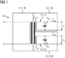
- Fig. 1 shows a high-voltage transformer 10 for an X-ray tube 20, which in Fig. 1 not shown, in an equivalent circuit diagram.
- the high-voltage transformer 10 has at least one primary winding 11.1, at least one first secondary winding 12.1 and at least one second secondary winding 12.2.
- the high-voltage transformer 10 may have further elements which in Fig. 1 not shown.
- the high voltage transformer 10 is shown in the equivalent circuit diagram as a real high voltage transformer.
- the high voltage transformer 10 is typically an asymmetrical high voltage transformer.
- the equivalent circuit of the high voltage transformer 10 is shown in FIG Fig. 1 divided into three areas B1, B2, B3, wherein the three areas B1, B2, B3 are each surrounded by dashed lines.
- the three areas B1, B2, B3 are equivalent circuits of the at least one primary winding 11.1, the at least one first secondary winding 12.1 and the at least one second secondary winding 12.2 shown.
- the at least one first secondary winding 12.1 has a first oscillating circuit 12.1.S, wherein the first resonant circuit 12.1.S has a first leakage inductance L ⁇ 1 and a first winding capacitance C W1 , which together set a first resonant frequency.
- the at least one second secondary winding 12.2 has a second oscillating circuit 12.2.S, wherein the second oscillating circuit 12.2.S has a second leakage inductance L ⁇ 2 and a second winding capacitance C W2 , which jointly set a second resonant frequency.
- the first resonance frequency and the second resonance frequency coincide.
- the first resonance frequency and the second resonance frequency correspond in terms of magnitude.
- the first winding capacitance C W1 and the second winding capacitance C W2 differ in magnitude and the first leakage inductance L ⁇ 1 and the second leakage inductance L ⁇ 2 differ in terms of absolute value.
- a first load current I1 is established, and in the at least one second secondary winding 12.1, a second load current I2 arises, in particular when the high-voltage transformer 10 is connected to an asymmetrical load.
- the first load current I1 flows in the first secondary winding 12.1 and the second load current I2 in the second secondary winding 12.2.
- the setting of the first load current I1 and / or the second load current I2 typically means that the high-voltage transformer 10 is loaded by operating a load, in particular the asymmetrical load.
- the first load current I1 sets typically a first high voltage U1 drops across the at least one first secondary winding 12.1.
- a second high voltage U2 typically drops across the at least one second secondary winding 12.2.
- the first high voltage U1 and the second high voltage U2 are typically AC voltages.
- the load is the asymmetric load
- the X-ray tube 20 is, preferably the first high voltage U1 with the second high voltage U2 equal in magnitude, wherein the first load current I1 differs from the second load current I2 amount.
- a voltage asymmetry at the high-voltage transformer 10 is preferably lower, particularly preferably avoided, because the first resonant frequency and the second resonant frequency coincide, the first coil capacitance C W1 and the second coil capacitance C W2 differ in magnitude and because the first leakage inductance L ⁇ 1 and differentiate the second leakage inductance L ⁇ 2 in terms of magnitude.
- the high voltage transformer 10 is preferably the asymmetrical high voltage transformer, and in operation with the asymmetrical load, particularly with the x-ray tube 20, the voltage asymmetry is lower as compared to when the high voltage transformer 10 is a conventional balanced high voltage transformer.
- the first load current I1 differs from the second load current I2, in particular in terms of magnitude, by a differential current 10.I ⁇ of the high-voltage transformer 10.
- the differential current 10.I ⁇ of the high-voltage transformer 10 is typically an alternating current.
- the differential current 10.I ⁇ of the high-voltage transformer 10 is proportional to a differential current 20.I ⁇ of the x-ray tube 20, which is typically a direct current.
- the differential current 20.I ⁇ of the X-ray tube 20 correlates with the differential current 10.I ⁇ of the high-voltage transformer 10.
- a rectifying mean value of the differential current 10.I ⁇ of the high-voltage transformer 10 and an amount of the differential current 20.I ⁇ of the X-ray tube 20 differ by a factor of 0, for example to 10, particularly advantageously by a factor of 2 to 3.
- the differential current 10.I ⁇ of the high-voltage transformer 10 is typically generated by the first winding capacitance C W1 and the second winding capacitance C W2 as well as the first leakage inductance L ⁇ 1 and the second leakage inductance L ⁇ 2 differ in terms of magnitude, wherein the first resonance frequency and the second resonance frequency coincide.
- the smaller the first leakage inductance L ⁇ 1 the higher the first load current I1.
- the higher the first winding capacitance C W1 the higher the first load current I1, in particular if the first resonance frequency and the second resonance frequency coincide.
- the differential current 20.I ⁇ of the x-ray tube 20 in the x-ray tube 20 is established.
- the differential current 20.I ⁇ of the X-ray tube 20 preferably flows in the X-ray tube 20.
- the electrons scattered back at an anode 22 of the X-ray tube 20 correspond in magnitude to the differential current 20.I ⁇ of the X-ray tube 20.
- the differential current 20.I ⁇ of the X-ray tube 20 preferably has the electrons backscattered at the anode 22 of the X-ray tube 20.
- the backscattering of the electrons at the anode 22 may include a rebound at the anode 22.
- the differential current 20.I ⁇ of the X-ray tube 20 may comprise further electrons which have not previously hit the anode 22, but are typically scattered directly from the cathode 21 to the metal central part 23.
- the differential current 20.I ⁇ of the X-ray tube 20 typically comprises less than 20%, in particular less than 10%, of all electrons emitted by the cathode 21.
- the differential current 20.I ⁇ of the X-ray tube 20 may be referred to as leakage current and / or parasitic current.
- leakage current and / or parasitic current In principle, it is conceivable for a number of electrons backscattered at the anode 22 of the x-ray tube 20 to vary in such a way that the high-voltage transformer 10, in particular the asymmetrical high-voltage transformer, has a low voltage asymmetry.
- the at least one primary winding 11.1, the at least one first secondary winding 12.1 and the at least one second secondary winding 12.2 are usually comparable. Therefore, in order to avoid unnecessary repetitions, the technical characteristics are preferably described below with reference to the at least one first secondary winding 12.1, wherein this description can be correspondingly transferred to the at least one primary winding 11.1 and / or the at least one second secondary winding 12.1.
- a transmission behavior of the high-voltage transformer 10 usually corresponds to a transmission behavior of the real high-voltage transformer.
- the at least one first secondary winding 12.1 typically has the first oscillating circuit 12.1.S in that the at least one first secondary winding 12.1 behaves in particular like an electrical circuit with the first leakage inductance L ⁇ 1 and with the first winding capacitance C W1 . In other words, the first leakage inductance L ⁇ 1 and the first winding capacitance C W1 usually generate the first oscillatory circuit 12.1.S of the at least one first secondary winding 12.1.
- the reference symbols C W1 , C W2 , L ⁇ 1 , L ⁇ 2 are also formula symbols C W1 , C W2 , L ⁇ 1 , L ⁇ 2 of the corresponding leakage inductances and winding capacitances.
- matching or matching in terms of amount means, in particular, that a first value, which is a first nonnegative real number, is equal to a second value, which is a second nonnegative real number. In other words, both values are the same. For example, if the first resonance frequency is 100 kHz as the first value and the second resonance frequency is 100 kHz as the second value, then the first value and the second value match.
- Difference in terms of amount means in particular that the first value is greater or less than the second value. For example, if the first winding capacitance C W1 is 200 nF as the first value and the second winding capacitance C W2 is 100 nF as the second value, then the first value and the second value differ because the second value is greater than the first value.
- Fig. 2 shows the high voltage transformer 10 in a schematic cross section.
- the high-voltage transformer 10 has a transformer core 13, wherein the at least one primary winding 11. 1, which is wound around the transformer core 13 at least a first secondary winding 12. 1 and the at least one second secondary winding 12. 2 according to a sheath winding.
- the at least one primary winding 11.1, the at least one first secondary winding 12.1 and the at least one second secondary winding 12.2 are wound around the same leg of the transformer core 13.
- the at least one primary winding 11.1, the at least one first secondary winding 12.1 and the at least one second secondary winding 12.2 are wound around two or three different legs of the transformer core 13.
- the transformer core 13 usually has a magnetic core of a soft magnetic material with high magnetic permeability.
- the high-voltage transformer 10 has a primary coil body and a secondary coil body.
- the primary coil body and / or the secondary coil body are typically non-metallic, in particular made of plastic.
- the primary coil body and the secondary coil body act as insulation between the windings 11.1, 12.1, 12.2 and the transformer core 13.
- the primary coil body and / or the secondary coil body have little, particularly advantageously no, influence on the leakage inductances L ⁇ 1 , L ⁇ 2 and the winding capacitances C. W1 , C W2 .
- the primary coil body and other typical components of the high voltage transformer 10 are in Fig. 2 not shown for reasons of clarity.
- the secondary coil body has a first secondary coil half 12.1.K and a second secondary coil half 12.2.K on.
- the first secondary coil half 12.1.K and the second secondary coil half 12.2.K may be formed as part of a single secondary coil body or as two separate parts of the secondary coil body, as in FIG Fig. 2 shown to be trained. In other words, the first secondary coil half 12.1.K can be structurally separated from the second secondary coil half 12.2.K.
- the first secondary coil half 12.1.K has the at least one first secondary winding 12.1 and the second secondary coil half 12.2.K has the at least one second secondary winding 12.2.
- the at least one first secondary winding 12.1 by means of the first Secondary coil half 12.1.K mechanically supported
- the at least one second secondary winding 12.2 by means of the second secondary coil half 12.2.K is mechanically supported.
- the at least one first secondary winding 12.1 is arranged around the second secondary coil half 12.1.K and the at least one second secondary winding 12.2 is arranged and / or wound around the second secondary coil half 12.2.K.
- the first secondary coil half 12.1.K and the second secondary coil half 12.2.K are constructed asymmetrically to one another.
- the asymmetric structure can be made from a mechanical measure and / or be obtained according to a selection of different materials for the formation of the windings 12.1, 12.2.
- the materials typically differ in material nature, such as electrical and / or magnetic conductivity.
- a spatial position of the at least one first secondary winding 12.1 differs from a spatial position of the at least one second secondary winding 12.2, typically due to the mechanical measure.
- the spatial position of the at least one first secondary winding 12.1 has, for example, a position, an orientation, a winding height and / or a diameter.
- the spatial position of the at least one first secondary winding 12.1 relative to the transformer core 13 influences a leakage flux, wherein the leakage flux typically correlates with the first leakage inductance L ⁇ 1 .
- the first winding capacitance C W1 typically varies when the spatial position of the at least one first secondary winding 12.1 is changed with respect to itself, in particular when the winding height of the at least one first secondary winding 12.1 is varied.
- a first diameter 12.1.D of the at least one first secondary winding 12.1 is smaller than a second diameter 12.2.D of the at least one second secondary winding 12.2, whereby the first leakage inductance L ⁇ 1 is smaller than the second leakage inductance L ⁇ 2 .
- a leakage flux through the at least one first secondary winding 12.1, in particular the losses is smaller in comparison to a leakage flux through the at least one second secondary winding 12.2. If the first diameter 12.1.D differs from the second diameter 12.2D, for example, the spatial position of the at least one first secondary winding 12.1 is different with respect to the spatial position of the at least one second secondary winding 12.2.
- the at least one first secondary winding 12.1 is arranged in a first chamber 12.1.C of the first secondary coil half 12.1.K, wherein the at least a second secondary winding 12.2 is disposed in a second chamber 12.2.C of the second secondary coil half 12.2.K, and wherein a first width 12.1.B of the first chamber 12.1.C is greater than a second width 12.2.B of the second chamber 12.2.C, thereby the first winding capacitance C W1 is greater than the second winding capacitance C W2 .
- the first chamber 12.1.C and the second chamber 12.2.C typically act such that the at least one first secondary winding 12.1 is mechanically held relative to the second secondary coil half 12.1.K and the at least one second secondary winding 12.2 is mechanically held relative to the second secondary coil half 12.2.K and / or are fixed.
- Each chamber 12.1.C, 12.2.C usually has webs, wherein the webs together with the secondary bobbin cause a U-shaped profile of the chambers 12.1.C, 12.2.C.
- the chambers 12.1.C, 12.2.C an O-shaped profile and / or without the webs have no profile.
- the high-voltage transformer 10 has at least one longitudinal axis 10.L, wherein the longitudinal axis 10.L is formed in this embodiment parallel to the x-axis.
- the first width 12.1.B and the second width 12.2.B describe in this embodiment, in particular, a width of the chambers 12.1.C, 12.2.C along the x-axis.
- the first diameter 12.1.D and the second diameter 12.2D are parallel to the z-axis in this embodiment.
- the at least one first secondary winding 12.1 and the at least one second secondary winding 12.2 have an equal number of winding wires.
- the at least one first secondary winding 12.1 and the at least one second secondary winding 12.2 have a plurality of winding wires.
- the winding wires are typically copper.
- a first winding height 12.1.H of the at least one first secondary winding 12.1 is usually less than one second winding height 12.2.H the at least one second secondary winding 12.2. If the first winding height 12.1.H of the at least one first secondary winding 12.1 is less than the second winding height 12.2.H of the at least one second secondary winding 12.2, usually the first leakage inductance L ⁇ 1 is smaller than the second leakage inductance L ⁇ 2 . Usually, therefore, the first leakage inductance L ⁇ 1 and the second leakage inductance L ⁇ 2 differ when the first width 12.1.B is different from the second width 12.2.B.
- a winding width is typically indirectly proportional to winding height 12.1.H, 12.2.H.
- a particularly advantageous embodiment may be when the first winding capacitance C W2 and the second winding capacitance C W2 and the first leakage inductance L ⁇ 1 and the second leakage inductance L ⁇ 2 differ in terms of amount, because the first width 12.1.B is greater than the second width 12.2 .B and because the first diameter 12.1.D is smaller than the second diameter 12.2D.
- Fig. 3 shows the high voltage transformer 10, in particular a spatial position of the at least one primary winding 11.1, a spatial position of the at least one first secondary winding 12.1 and a spatial position of the at least one second secondary winding 12.2 relative to each other, in a scheme according to an asymmetric structure.
- the at least one primary winding 11.1 forms a first cylinder 11.Z with a first longitudinal axis 11.L, wherein the at least one first secondary winding 12.1 and the at least one second secondary winding 12.2 together form a second cylinder 12.Z with a second longitudinal axis 12.L.
- the imaginary forming of the cylinders serves in particular the purpose of representing the position relative to one another.
- the at least one primary winding 11.1, the at least one first secondary winding 12.1 and / or the at least one second secondary winding 12.2 may be cylindrically shaped.
- the first longitudinal axis 11.L is parallel to the second longitudinal axis 12.L and to the in Fig. 3 formed x-axis formed.
- the first longitudinal axis 11.L is congruent to the second longitudinal axis 12.L.
- the first cylinder 11.Z has a first centerline 11.M, the second cylinder 12.Z having a second centerline 12.M.
- the first center line 11.M and the second center line 12.M each indicate a center of the first cylinder 11.Z and the second cylinder 12.Z, respectively.
- the first cylinder 11.Z is arranged offset relative to the second cylinder 12.Z along the first longitudinal axis 11.L, in particular by the offset Vx.
- the first centerline 11.M is displaced along the first longitudinal axis 11.L, in particular along the x-axis, by the offset Vx relative to the second center line 12.M.
- the first cylinder 11.Z is displaced relative to the second cylinder along the z-axis and / or along the y-axis.
- the first cylinder 11.Z may be offset relative to the second cylinder 12.Z by an offset in each of the spatial directions, whereby the first cylinder 11.Z is rotated relative to the second cylinder 12.Z can be arranged.
- Staggered may mean that the first cylinder 11.Z is displaced relative to the second cylinder 12.Z from a common center out.
- the first leakage inductance L ⁇ 1 of the second leakage inductance L ⁇ 2 typically differs in magnitude.
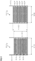
- Fig. 4 shows the high-voltage transformer 10, in particular the first chamber 12.1.C and the second chamber 12.2.C, in a schematic cross section.
- the at least one first secondary winding 12.1 is arranged in the first chamber 12.1.C of the first secondary coil half 12.1.K together with at least one first paper insulation layer 12.1.P.
- the at least one second secondary winding 12.2 is arranged in the second chamber 12.2.C of the second secondary coil half 12.2.K together with at least one second paper insulation layer 12.2.P.
- the first chamber 12.1.C and the second chamber 12.2.C have the U-shaped profile. In contrast to the in Fig. 2 In the embodiment shown, the first width 12.1.B of the first chamber 12.1.C is equal in magnitude to the second width 12.2.B of the second chamber 12.2.C.
- An arrangement of the first paper insulation layer 12.1.P relative to the at least one first secondary winding 12.1 differs from an arrangement of the second paper insulation layer 12.2.P relative to the at least one second secondary winding 12.2.
- the at least one first secondary winding 12.1 and the at least one second secondary winding 12.2 have the same number of winding wires, wherein the winding wires in this embodiment in each case 12 winding layers in the first chamber 12.1.C and in the second Chamber 12.2.C are arranged.
- the first paper insulation layer 12.1.P comprises, for example, three separation layers, while the second paper insulation layer 12.2.P comprises five separation layers, whereby the first winding height 12.1.H is smaller than the second winding height 12.2.H.
- the first winding capacitance C W1 is greater than the second winding capacitance C W2 in this embodiment. Typically, the more winding layers per separation layer, the larger the winding capacitances C W1 , C W2 .
- Fig. 5 shows a circuit arrangement 30 in a block diagram.
- the circuit arrangement 30 comprises the high-voltage transformer 10 and the X-ray tube 20.
- the x-ray tube 20 has a cathode 21 and an anode 22.
- the at least one first secondary winding 12.1 is electrically connected to the cathode 21 and the at least one second secondary winding 12.2 is electrically connected to the anode 22.
- the inverter circuit 32 may include a half-bridge and / or a full-bridge circuit.
- a rectifier 33 is connected on an output side.
- the rectifier 33 may be a voltage doubler rectifier.
- the rectifier 33 typically has the differential current 10.I ⁇ of the high-voltage transformer 10 on a first side and / or the differential current 20.I ⁇ of the x-ray tube 20 on a second side.
- the x-ray tube 20 has a metal middle part 23.
- the differential current 20.I ⁇ of the X-ray tube 20 is established between the anode 22 and the metal middle part 23.
- the metal center part 23 is typically grounded, over which the differential current 20.I ⁇ of the X-ray tube 20 flows.
- At least one resonant circuit choke between the high voltage transformer 10 and the X-ray tube 20 is connected.
- the first leakage inductance L ⁇ 1 and / or the second leakage inductance L ⁇ 2 can be influenced and / or adjusted by means of the at least one resonant circuit choke .
- At least one capacitor is connected between the high-voltage transformer 10 and the x-ray tube 20, in particular parallel to the at least one first secondary winding 12.1 and / or parallel to the at least one second secondary winding 12.2.
- the first winding capacitance C W1 and / or the second winding capacitance C W2 can be influenced and / or adjusted by means of the at least one capacitor.
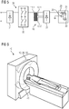
- Fig. 6 shows an X-ray device 40.
- the X-ray device 40 has the circuit arrangement 30.
- the X-ray device 40 has an X-ray detector 41, which can detect an X-ray radiation generated at the anode 22.
- the X-ray device 40 can be used, for example, for medical imaging, in particular an angiography examination. In principle, it is conceivable that non-medical imaging is performed by means of the X-ray device 40.
- the X-ray device 40 is designed as a computer tomograph.
- the computer tomograph has a patient couch around which typically the x-ray tube 20 and the x-ray detector 41 are rotatably mounted.
- the high-voltage transformer 10 is constructed in such a way that the at least one primary winding 11.1 is stationary, while the at least one first secondary winding 12.1 and the at least one second secondary winding 12.2 rotate around the patient bed with the x-ray tube 20 and the x-ray detector 41.
- the high-voltage transformer 10 is used in particular for transmitting power for the operation of the X-ray tube 20 and / or the X-ray detector 41. Basically conceivable that 10 data are transmitted by means of the high voltage transformer.
Landscapes
- Engineering & Computer Science (AREA)
- Power Engineering (AREA)
- Health & Medical Sciences (AREA)
- Life Sciences & Earth Sciences (AREA)
- Medical Informatics (AREA)
- General Health & Medical Sciences (AREA)
- Nuclear Medicine, Radiotherapy & Molecular Imaging (AREA)
- Radiology & Medical Imaging (AREA)
- Physics & Mathematics (AREA)
- Pathology (AREA)
- Heart & Thoracic Surgery (AREA)
- Surgery (AREA)
- Veterinary Medicine (AREA)
- Public Health (AREA)
- Animal Behavior & Ethology (AREA)
- Molecular Biology (AREA)
- Biophysics (AREA)
- High Energy & Nuclear Physics (AREA)
- Biomedical Technology (AREA)
- Optics & Photonics (AREA)
- Theoretical Computer Science (AREA)
- Pulmonology (AREA)
- Chemical & Material Sciences (AREA)
- Biochemistry (AREA)
- Immunology (AREA)
- General Physics & Mathematics (AREA)
- Analytical Chemistry (AREA)
- X-Ray Techniques (AREA)
- Apparatus For Radiation Diagnosis (AREA)
Abstract
Description
- Die Erfindung betrifft einen Hochspannungstransformator für eine Röntgenröhre, eine Schaltungsanordnung, eine Röntgeneinrichtung und einen Computertomographen.
- Zu einer Versorgung einer Röntgenröhre mit Hochspannung werden typischerweise Hochspannungstransformatoren eingesetzt. Auf einer Kathodenseite liefert der Hochspannungstransformator beispielsweise eine relativ zu einem Erdpotential negative Hochspannung und auf einer Anodenseite eine relativ zu dem Erdpotential positive Hochspannung. Insbesondere eine daraus resultierende Hochspannung zwischen einer Anode der Röntgenröhre und einer Kathode der Röntgenröhre beschleunigt aus der Kathode emittierte Elektronen, welche üblicherweise auf der Anode auftreffen und dabei abgebremst werden, wodurch insbesondere Röntgenstrahlung für eine Bildgebung entsteht. Allerdings wird typischerweise ein gewisser Anteil der emittierten Elektronen an der Anode zurückgestreut.
- Die zurückgestreuten Elektronen werden beispielsweise von einem geerdeten Metallmittelteil der Röntgenröhre eingefangen, wodurch sich insbesondere ein Differenzstrom in der Röntgenröhre einstellt. Daher wirkt die Röntgenröhre insbesondere als asymmetrische Last. Aufgrund des Differenzstroms der Röntgenröhre wird typischerweise der Hochspannungstransformator auf der Anodenseite und auf der Kathodenseite in Bezug auf einen jeweiligen Laststrom asymmetrisch belastet. In anderen Worten stellt sich zwischen der Anodenseite und der Kathodenseite ein Differenzstrom des Hochspannungstransformators ein, welcher zum Differenzstrom der Röntgenröhre proportional ist. Typischerweise korreliert also der Differenzstrom der Röntgenröhre mit dem Differenzstrom des Hochspannungstransformators. Der Differenzstrom des Hochspannungstransformators entsteht insbesondere dadurch, dass sich der Laststrom auf der Anodenseite und der Laststrom auf der Kathodenseite unterscheiden, insbesondere asymmetrisch sind. In diesem Fall folgt typischerweise eine Spannungsasymmetrie am Hochspannungstransformator. Allerdings ist ein herkömmlicher Hochspannungstransformator üblicherweise symmetrisch aufgebaut, weshalb sich am herkömmlichen Hochspannungstransformator aufgrund des Differenzstroms der Röntgenröhre die Spannungsasymmetrie einstellen kann. Die Spannungsasymmetrie folgt insbesondere daraus, dass sich insbesondere unterschiedliche Hochspannungen auf der Anodenseite und der Kathodenseite einstellen. Durch die Spannungsasymmetrie kann der Hochspannungstransformator und/oder die Röntgenröhre Schaden nehmen. Des Weiteren kann sich eine Qualität der Bildgebung verringern, falls der Hochspannungstransformator für die Röntgenröhre bei der Bildgebung verwendet wird.
- Üblicherweise werden daher zwei voneinander unabhängige Hochspannungstransformatoren eingesetzt, wobei durch eine unabhängige Regelung der kathodenseitigen und anodenseitigen Hochspannungen die Spannungsasymmetrie verhindert werden kann. Dadurch steigen Herstellungs- und Wartungskosten erheblich an. Denn typischerweise müssen aufgrund der beiden Hochspannungstransformatoren noch weitere Einheiten, insbesondere Hochspannungswechselrichter und/oder zugehörige Schwingkreisdrosseln, ebenfalls mehrfach verbaut werden.
- Eine alternative Möglichkeit ist ein Einsatz eines Mittelspannungstransformators mit nachgeschalteter Hochspannungskaskade, wodurch eine Komplexität einer Schaltungsanordnung mit dem Mittelspannungstransformator, der Hochspannungskaskade sowie der Röntgenröhre und damit ebenfalls die Kosten ansteigen.
- Der Erfindung liegt die Aufgabe zu Grunde, einen Hochspannungstransformator für eine Röntgenröhre, eine Schaltungsanordnung, eine Röntgeneinrichtung und einen Computertomographen anzugeben, bei welchen eine Spannungsasymmetrie aufgrund einer asymmetrischen Last verringert wird.
- Die Aufgabe wird durch die Merkmale der unabhängigen Ansprüche gelöst. Vorteilhafte Ausgestaltungen sind in den Unteransprüchen beschrieben.
- Bauartbedingt können sich bei elektronischen Schaltungen oder Bauelementen in einer realen Umgebung Abweichungen von den Vorgaben in einer idealen Umgebung ergeben. Wenn im Folgenden von Übereinstimmung, Entsprechung, Baugleichheit etc. gesprochen wird, beziehen sich diese Formulierungen in erster Linie auf eine Definition oder Dimensionierung der Schaltung oder des Bauelements in der idealen Umgebung. In der realen Umgebung können sich dennoch Abweichungen ergeben, obwohl diese Abweichung der Schaltung oder des Bauelements typischerweise nicht vorgesehen ist. Die ideale Umgebung kann beispielsweise eine Software zum Entwurf eines Hochspannungstransformators sein.
- Der erfindungsgemäße Hochspannungstransformator für eine Röntgenröhre weist
- zumindest eine Primärwicklung,
- zumindest eine erste Sekundärwicklung, welche einen ersten Schwingkreis aufweist, wobei der erste Schwingkreis eine erste Streuinduktivität und eine erste Wicklungskapazität aufweist, welche gemeinsam eine erste Resonanzfrequenz einstellen, und
- zumindest eine zweite Sekundärwicklung auf, welche einen zweiten Schwingkreis aufweist, wobei der zweite Schwingkreis eine zweite Streuinduktivität und eine zweite Wicklungskapazität aufweist, welche gemeinsam eine zweite Resonanzfrequenz einstellen,
- wobei die erste Resonanzfrequenz und die zweite Resonanzfrequenz übereinstimmen,
- wobei sich die erste Wicklungskapazität und die zweite Wicklungskapazität betragsmäßig unterscheiden und
- wobei sich die erste Streuinduktivität und die zweite Streuinduktivität betragsmäßig unterscheiden.
- Der Hochspannungstransformator bietet insbesondere folgende Vorteile: eine asymmetrische Last, insbesondere die Röntgenröhre, kann mit einer mittels des Hochspannungstransformator erzeugter Hochspannung betrieben werden. Vorteilhafterweise kann mittels des Hochspannungstransformators allein eine Reduzierung einer Spannungsasymmetrie erfolgen, wodurch ein Wartungsaufwand des Hochspannungstransformators vorzugsweise geringer ausfällt. Durch die Reduzierung der Spannungsasymmetrie können vorzugsweise bei einer Bildgebung Messdaten mit einer hohen Bildqualität erfasst werden, falls der Hochspannungstransformator bei der Bildgebung eingesetzt wird. Die Reduzierung der Spannungsasymmetrie erfolgt vorzugsweise ohne zusätzliche Bauelemente, welche typischerweise die asymmetrische Last ausgleichen sollen.
- Der Hochspannungstransformator ist insbesondere vorteilhaft, weil der Hochspannungstransformator typischerweise eine höhere Leistungsdichte im Vergleich zu zwei herkömmlichen symmetrischen Hochspannungstransformatoren in Parallelschaltung aufweist.
- Vorteilhafterweise kann durch das Abstimmen der ersten Resonanzfrequenz und der zweiten Resonanzfrequenz die Spannungsasymmetrie über einen Betriebsfrequenzbereich, insbesondere eines für die Hochspannungserzeugung eingesetzten Resonanzwandlers, gering gehalten werden.
- Eine Ausführungsform sieht vor, dass sich in der zumindest einen ersten Sekundärwicklung ein erster Laststrom einstellt, wobei sich in der zumindest einen zweiten Sekundärwicklung ein zweiter Laststrom einstellt, wobei sich der erste Laststrom von dem zweiten Laststrom um einen Differenzstrom des Hochspannungstransformators unterscheidet, welcher zu einem Differenzstrom der Röntgenröhre proportional ist. Vorzugsweise ist der Differenzstrom des Hochspannungstransformators, insbesondere der erste Laststrom und der zweite Laststrom derart dimensioniert, dass die Spannungsasymmetrie am Hochspannungstransformator verringert wird. Besonders vorteilhafterweise entsprechen sich die kathodenseitige Hochspannung und die anodenseitige Hochspannung betragsmäßig, vorzugsweise trotz der asymmetrischen Last, insbesondere trotz des Differenzstroms der Röntgenröhre. Der Hochspannungstransformator gleicht also die Spannungsasymmetrie vorzugweise aus. Vorteilhafterweise ist der Hochspannungstransformator in Abhängigkeit von der asymmetrischen Last, insbesondere von der Röntgenröhre, ausgebildet. Der Hochspannungstransformator bietet also den Vorteil einer individuellen Anpassung an die asymmetrische Last.
- Eine Ausführungsform sieht vor, dass die zumindest eine Primärwicklung einen ersten Zylinder mit einer ersten Längsachse bildet, wobei die zumindest eine erste Sekundärwicklung und die zumindest eine zweite Sekundärwicklung gemeinsam einen zweiten Zylinder mit einer zweiten Längsachse bilden, wobei die erste Längsachse parallel zur zweiten Längsachse ist und wobei der erste Zylinder relativ zum zweiten Zylinder entlang der ersten Längsachse versetzt angeordnet ist. Die versetzte Anordnung des ersten Zylinders relativ zum zweiten Zylinder ist insbesondere vorteilhaft, weil eine entsprechende bauliche Maßnahme einfach durchgeführt werden kann. Vorteilhafterweise sind mittels dieser Ausführungsform die Streuinduktiväten präzise einstellbar.
- Eine Ausführungsform sieht vor, dass sich ein Wicklungsdraht der zumindest einen ersten Sekundärwicklung von einem Wicklungsdraht der zumindest einen zweiten Sekundärwicklung gemäß zumindest einem Parameter der folgenden Liste unterscheidet:
- einer Dicke des Wicklungsdrahts,
- einer Dicke einer Lackisolationsschicht des Wicklungsdrahts,
- einer Dielektrizitätszahl der Lackisolationsschicht des Wicklungsdrahts. Eine Variation einer Ausführung des Wicklungsdrahts der zumindest einen ersten Sekundärwicklung von einer Ausführung des Wicklungsdrahts der zumindest einen zweiten Sekundärwicklung ist vorteilhaft, weil diese Variation mehrmals durchgeführt werden kann. Vorzugsweise kann die zumindest eine erste Sekundärwicklung und/oder die zumindest eine zweite Sekundärwicklung einfach ausgetauscht werden. Vorteilhafterweise sind mittels dieser Ausführungsform die Wicklungskapazitäten präzise einstellbar.
- Eine Ausführungsform sieht vor, dass ein erster Durchmesser der zumindest einen ersten Sekundärwicklung kleiner ist als ein zweiter Durchmesser der zumindest einen zweiten Sekundärwicklung, wodurch die erste Streuinduktivität kleiner ist als die zweite Streuinduktivität. Durch die Verwendung von unterschiedlichen Durchmessern kann vorteilhafterweise eine Größe des Hochspannungstransformators verringert werden. Vorteilhafterweise kann weiterhin derart auf eine Verschaltung einer zusätzlichen Schwingkreisdrossel zur Einstellung der Induktivität mit dem Hochspannungstransformator verzichtet werden, wodurch Kosten und Bauraum eingespart werden. Vorteilhafterweise sind mittels dieser Ausführungsform die Streuinduktiväten präzise einstellbar.
- Eine Ausführungsform sieht vor, dass der Hochspannungstransformator einen Primärspulenkörper und einen Sekundärspulenkörper aufweist, wobei der Sekundärspulenkörper eine erste Sekundärspulenhälfte und eine zweite Sekundärspulenhälfte aufweist, wobei die erste Sekundärspulenhälfte die zumindest eine erste Sekundärwicklung aufweist, wobei die zweite Sekundärspulenhälfte die zumindest eine zweite Sekundärwicklung aufweist und wobei die erste Sekundärspulenhälfte und die zweite Sekundärspulenhälfte asymmetrisch zueinander aufgebaut sind. Vorzugsweise kann der Hochspannungstransformator die asymmetrische Last betreiben, ohne dass ein weiterer Hochspannungstransformator an die asymmetrische Last angeschlossen ist. In anderen Worten ist der Hochspannungstransformator ein asymmetrischer Hochspannungstransformator, welcher für eine asymmetrische Last, insbesondere die Röntgenröhre, ausgebildet ist. Da typischerweise lediglich der Hochspannungstransformator ohne den weiteren Hochspannungstransformator für den Betrieb der Röntgenröhre bereitgestellt wird, sinken die Kosten und der Bauraum. Vorteilhafterweise kann ein Grad einer Asymmetrie der asymmetrischen Last, insbesondere der Röntgenröhre, ermittelt werden, wobei der Hochspannungstransformator danach vorzugsweise gemäß dem Grad der Asymmetrie entworfen wird. In anderen Worten wird typischerweise in einer Laborumgebung der Grad der Asymmetrie ermittelt und/oder gemessen und daraufhin der Hochspannungstransformator an die asymmetrische Last derart angepasst, dass die Spannungsasymmetrie verringert ist.
- Eine Ausführungsform sieht vor, dass die zumindest eine erste Sekundärwicklung in einer ersten Kammer der ersten Sekundärspulenhälfte gemeinsam mit zumindest einer ersten Papierisolationslage angeordnet ist, wobei die zumindest eine zweite Sekundärwicklung in einer zweiten Kammer der zweiten Sekundärspulenhälfte gemeinsam mit zumindest einer zweiten Papierisolationslage angeordnet ist und wobei sich eine Anordnung der ersten Papierisolationslage relativ zu der zumindest einen ersten Sekundärwicklung von einer Anordnung der zweiten Papierisolationslage relativ zu der zumindest einen zweiten Sekundärwicklung unterscheidet. Vorteilhafterweise kann jede Anordnung der Papierisolationslage einfach an die asymmetrische Last angepasst werden. Vorteilhafterweise sind mittels dieser Ausführungsform die Wicklungskapazitäten präzise einstellbar.
- Eine Ausführungsform sieht vor, dass die zumindest eine erste Sekundärwicklung in einer ersten Kammer der ersten Sekundärspulenhälfte angeordnet ist, wobei die zumindest eine zweite Sekundärwicklung in einer zweiten Kammer der zweiten Sekundärspulenhälfte angeordnet ist und wobei eine erste Breite der ersten Kammer größer ist als eine zweite Breite der zweiten Kammer, wodurch die erste Wicklungskapazität größer ist als die zweite Wicklungskapazität. Diese Ausführungsform bietet insbesondere den Vorteil, dass diese bauliche Maßnahme, nämlich das Variieren der Breite der Kammern, vorzugsweise einen robusten Hochspannungstransformator ermöglicht. Vorteilhafterweise sind mittels dieser Ausführungsform die Wicklungskapazitäten präzise einstellbar.
- Eine Ausführungsform sieht vor, dass der erste Durchmesser der zumindest einen ersten Sekundärwicklung kleiner ist als der zweite Durchmesser der zumindest einen zweiten Sekundärwicklung und dass die erste Breite der ersten Kammer größer ist als die zweite Breite der zweiten Kammer. Vorteilhafterweise stimmt die erste Resonanzfrequenz und die zweite Resonanzfrequenz überein, obwohl sich die erste Wicklungskapazität und die zweite Wicklungskapazität sowie die erste Streuinduktivität und die zweite Streuinduktivität betragsmäßig unterscheiden. Vorteilhafterweise sind mittels dieser Ausführungsform die Wicklungskapazitäten und die Streuinduktivitäten präzise einstellbar.
- Die erfindungsgemäße Schaltungsanordnung weist
- den Hochspannungstransformator und
- die Röntgenröhre auf, welche eine Kathode und eine Anode aufweist,
- wobei die zumindest eine erste Sekundärwicklung mit der Kathode elektrisch verbunden ist und
- wobei die zumindest eine zweite Sekundärwicklung mit der Anode elektrisch verbunden ist. Die Schaltungsanordnung bietet insbesondere den Vorteil, dass der, insbesondere asymmetrische, Hochspannungstransformator, mit der, insbesondere als asymmetrische Last wirkende, Röntgenröhre elektrisch verbunden sein kann, wodurch der Betrieb der Röntgenröhre mittels des Hochspannungstransformators ermöglicht ist.
- Eine Ausführungsform sieht vor, dass die Röntgenröhre ein Metallmittelteil aufweist und wobei sich der Differenzstrom der Röntgenröhre zwischen der Anode und dem Metallmittelteil einstellt. Diese Ausführungsform bietet den Vorteil, dass die Spannungsasymmetrie am Hochspannungstransformator trotz der an der Anode zurückgestreuten Elektronen gering ausfällt.
- Eine Ausführungsform sieht vor, dass zumindest eine Schwingkreisdrossel zwischen dem Hochspannungstransformator und der Röntgenröhre verschaltet ist. Diese Ausführungsform bietet insbesondere den Vorteil, dass der Hochspannungstransformator kleiner ausgebildet ist, wenn die zumindest eine Schwingkreisdrossel zusätzlich außerhalb des Hochspannungstransformators angeordnet ist.
- Eine Ausführungsform sieht vor, dass zumindest ein Kondensator zwischen dem Hochspannungstransformator und der Röntgenröhre verschaltet ist. Diese Ausführungsform bietet insbesondere den Vorteil, dass der Hochspannungstransformator kleiner ausgebildet ist, wenn der zumindest eine Kondensator zusätzlich außerhalb des Hochspannungstransformators angeordnet ist.
- Die erfindungsgemäße Röntgeneinrichtung weist eine Schaltungsanordnung auf. Eine Fertigungszeit der Röntgeneinrichtung mit dem Hochspannungstransformator ist vorteilhafterweise geringer, weil typischerweise zur Reduzierung der Spannungsasymmetrie lediglich der Hochspannungstransformator gefertigt werden muss.
- Die erfindungsgemäße Computertomograph weist die Röntgeneinrichtung auf. Der Computertomograph ist vorzugsweise kleiner im Vergleich zu einem herkömmlichen Computertomograph mit zwei herkömmlichen Hochspannungstransformatoren in Parallelschaltung. Typischerweise ist der Computertomograph günstiger herzustellen, weil die asymmetrische Last vorzugsweise mit dem asymmetrischen Hochspannungstransformator verbunden ist.
- Im Folgenden wird die Erfindung anhand der in den Figuren dargestellten Ausführungsbeispiele näher beschrieben und erläutert. Grundsätzlich werden in der folgenden Figurenbeschreibung im Wesentlichen gleich bleibende Strukturen und Einheiten mit demselben Bezugszeichen wie beim erstmaligen Auftreten der jeweiligen Struktur oder Einheit benannt.
- Es zeigen:
-
Fig. 1 ein Ersatzschaltbild eines Hochspannungstransformators in einem ersten Ausführungsbeispiel, -
Fig. 2 einen schematischen Querschnitt durch einen Hochspannungstransformator in einem zweiten Ausführungsbeispiel, -
Fig. 3 einen schematischen asymmetrischen Aufbau eines Hochspannungstransformator in einem dritten Ausführungsbeispiel, -
Fig. 4 einen schematischen Querschnitt durch einen Hochspannungstransformator in einem vierten Ausführungsbeispiel, -
Fig. 5 ein Blockschaltbild einer Schaltungsanordnung in einem fünften Ausführungsbeispiel und -
Fig. 6 eine Röntgeneinrichtung in einem sechsten Ausführungsbeispiel. -
Fig. 1 zeigt einen Hochspannungstransformator 10 für eine Röntgenröhre 20, welche inFig. 1 nicht gezeigt ist, in einem Ersatzschaltbild. Der Hochspannungstransformator 10 weist zumindest eine Primärwicklung 11.1, zumindest eine erste Sekundärwicklung 12.1 und zumindest eine zweite Sekundärwicklung 12.2 auf. Der Hochspannungstransformator 10 kann weitere Elemente aufweisen, welche inFig. 1 nicht gezeigt sind. - Der Hochspannungstransformator 10 ist in dem Ersatzschaltbild als realer Hochspannungstransformator abgebildet. Der Hochspannungstransformator 10 ist typischerweise ein asymmetrischer Hochspannungstransformator.
- Das Ersatzschaltbild des Hochspannungstransformators 10 ist in
Fig. 1 in drei Bereiche B1, B2, B3 aufgeteilt, wobei die drei Bereiche B1, B2, B3 jeweils mit gestrichelten Linien umrandet sind. In den drei Bereichen B1, B2, B3 sind Ersatzschaltungen der zumindest eine Primärwicklung 11.1, der zumindest eine erste Sekundärwicklung 12.1 und der zumindest eine zweite Sekundärwicklung 12.2 abgebildet. - Die zumindest eine erste Sekundärwicklung 12.1 weist einen ersten Schwingkreis 12.1.S auf, wobei der erste Schwingkreis 12.1.S eine erste Streuinduktivität Lσ1 und eine erste Wicklungskapazität CW1 aufweist, welche gemeinsam eine erste Resonanzfrequenz einstellen.
- Die zumindest eine zweite Sekundärwicklung 12.2 weist einen zweiten Schwingkreis 12.2.S auf, wobei der zweite Schwingkreis 12.2.S eine zweite Streuinduktivität Lσ2 und eine zweite Wicklungskapazität CW2 aufweist, welche gemeinsam eine zweite Resonanzfrequenz einstellen.
- Die erste Resonanzfrequenz und die zweite Resonanzfrequenz stimmen überein. In anderen Worten entsprechen sich die erste Resonanzfrequenz und die zweite Resonanzfrequenz betragsmäßig. Die erste Wicklungskapazität CW1 sowie die zweite Wicklungskapazität CW2 unterscheiden sich betragsmäßig und die erste Streuinduktivität Lσ1 sowie die zweite Streuinduktivität Lσ2 unterscheiden sich betragsmäßig.
- In der zumindest einen ersten Sekundärwicklung 12.1 stellt sich ein erster Laststrom I1 ein und in der zumindest einen zweiten Sekundärwicklung 12.1 stellt sich ein zweiter Laststrom I2 ein, insbesondere wenn der Hochspannungstransformator 10 mit einer asymmetrischen Last verbunden ist. In anderen Worten fließt der erste Laststrom I1 in der ersten Sekundärwicklung 12.1 und der zweite Laststrom I2 in der zweiten Sekundärwicklung 12.2. Das Einstellen des ersten Laststroms I1 und/oder des zweiten Laststroms I2 bedeutet typischerweise, dass der Hochspannungstransformator 10 durch ein Betreiben einer Last, insbesondere der asymmetrischen Last, belastet wird. Wenn sich der erste Laststrom I1 einstellt, fällt typischerweise eine erste Hochspannung U1 über der zumindest einen ersten Sekundärwicklung 12.1 ab. Wenn sich der zweite Laststrom I2 einstellt, fällt typischerweise eine zweite Hochspannung U2 über der zumindest einen zweiten Sekundärwicklung 12.2 ab. Die erste Hochspannung U1 und die zweite Hochspannung U2 sind typischerweise Wechselspannungen.
- Wenn die Last die asymmetrische Last, beispielsweise die Röntgenröhre 20, ist, stimmen vorzugsweise die erste Hochspannung U1 mit der zweiten Hochspannung U2 betragsmäßig überein, wobei sich der erste Laststrom I1 von dem zweiten Laststrom I2 betragsmäßig unterscheidet. In diesem Fall ist vorzugsweise eine Spannungsasymmetrie am Hochspannungstransformator 10 dadurch geringer, besonders vorzugsweise vermieden, weil die erste Resonanzfrequenz und die zweite Resonanzfrequenz übereinstimmen, sich die erste Wicklungskapazität CW1 und die zweite Wicklungskapazität CW2 betragsmäßig unterscheiden und weil sich die erste Streuinduktivität Lσ1 und die zweite Streuinduktivität Lσ2 betragsmäßig unterscheiden. In anderen Worten ist der Hochspannungstransformator 10 vorzugsweise der asymmetrische Hochspannungstransformator, wobei im Betrieb mit der asymmetrischen Last, insbesondere mit der Röntgenröhre 20, die Spannungsasymmetrie geringer ist im Vergleich dazu, wenn der Hochspannungstransformator 10 ein herkömmlicher symmetrischer Hochspannungstransformator ist.
- Der erste Laststrom I1 unterscheidet sich von dem zweiten Laststrom I2, insbesondere betragsmäßig, um einen Differenzstrom 10.IΔ des Hochspannungstransformators 10. Der Differenzstrom 10.IΔ des Hochspannungstransformators 10 ist typischerweise ein Wechselstrom.
- Der Differenzstrom 10.IΔ des Hochspannungstransformators 10 ist proportional zu einem Differenzstrom 20.IΔ der Röntgenröhre 20, welcher typischerweise ein Gleichstrom ist. In anderen Worten korreliert der Differenzstrom 20.IΔ der Röntgenröhre 20 mit dem Differenzstrom 10.IΔ des Hochspannungstransformators 10. Ein Gleichrichtmittelwert des Differenzstroms 10.IΔ des Hochspannungstransformators 10 und ein Betrag des Differenzstroms 20.IΔ der Röntgenröhre 20 unterscheiden sich beispielsweise um einen Faktor 0 bis 10, besonders vorteilhafterweise um einen Faktor 2 bis 3.
- Der Differenzstrom 10.IΔ des Hochspannungstransformators 10 wird typischerweise dadurch erzeugt, dass sich die erste Wicklungskapazität CW1 und die zweite Wicklungskapazität CW2 sowie die erste Streuinduktivität Lσ1 und die zweite Streuinduktivität Lσ2 betragsmäßig unterscheiden, wobei die erste Resonanzfrequenz und die zweite Resonanzfrequenz übereinstimmen. Typischerweise ist der erste Laststrom I1 desto höher, je kleiner die erste Streuinduktivität Lσ1 ist. Alternativ oder zusätzlich ist der erste Laststrom I1 desto höher, je größer die erste Wicklungskapazität CW1 ist, insbesondere wenn die erste Resonanzfrequenz und die zweite Resonanzfrequenz übereinstimmen.
- In einem Ausführungsbeispiel stellt sich der Differenzstrom 20.IΔ der Röntgenröhre 20 in der Röntgenröhre 20 ein. In anderen Worten fließt der Differenzstrom 20.IΔ der Röntgenröhre 20 vorzugsweise in der Röntgenröhre 20 ab. Besonders vorteilhafterweise entsprechen die an einer Anode 22 der Röntgenröhre 20 zurückgestreuten Elektronen betragsmäßig dem Differenzstrom 20.IΔ der Röntgenröhre 20. In anderen Worten weist der Differenzstrom 20.IΔ der Röntgenröhre 20 vorzugsweise die an der Anode 22 der Röntgenröhre 20 zurückgestreuten Elektronen auf. Das Zurückstreuen der Elektronen an der Anode 22 kann ein Abprallen an der Anode 22 umfassen. Der Differenzstrom 20.IΔ der Röntgenröhre 20 kann weitere Elektronen umfassen, welche vorher nicht an der Anode 22 aufgetroffen sind, sondern typischerweise direkt von der Kathode 21 zum Metallmittelteil 23 gestreut werden. Der Differenzstrom 20.IΔ der Röntgenröhre 20 umfasst typischerweise weniger als 20%, insbesondere weniger als 10%, aller von der Kathode 21 emittierten Elektronen.
- Der Differenzstrom 20.IΔ der Röntgenröhre 20 kann als Verluststrom und/oder parasitärer Strom bezeichnet werden. Grundsätzlich ist es denkbar, dass eine Anzahl von an der Anode 22 der Röntgenröhre 20 zurückgestreuten Elektronen derart variiert, dass der Hochspannungstransformator 10, insbesondere der asymmetrische Hochspannungstransformator, eine geringe Spannungsasymmetrie aufweist.
- Es ist allgemein bekannt, dass im Hinblick auf technische Eigenschaften die zumindest eine Primärwicklung 11.1, die zumindest eine erste Sekundärwicklung 12.1 und die zumindest eine zweite Sekundärwicklung 12.2 üblicherweise vergleichbar sind. Daher werden im Folgenden, um unnötige Wiederholungen zu vermeiden, die technischen Eigenschaften vorzugsweise in Bezug auf die zumindest eine erste Sekundärwicklung 12.1 beschrieben, wobei diese Beschreibung entsprechend auf die zumindest eine Primärwicklung 11.1 und/oder die zumindest eine zweite Sekundärwicklung 12.1 übertragen werden kann.
- Wenn die zumindest eine erste Sekundärwicklung 12.1 den ersten Schwingkreis 12.1.S aufweist, entspricht ein Übertragungsverhalten des Hochspannungstransformators 10 üblicherweise einem Übertragungsverhalten des realen Hochspannungstransformators. Die zumindest eine erste Sekundärwicklung 12.1 weist den ersten Schwingkreis 12.1.S typischerweise dadurch auf, dass die zumindest eine erste Sekundärwicklung 12.1 sich insbesondere wie eine elektrische Schaltung mit der ersten Streuinduktivität Lσ1 und mit der ersten Wicklungskapazität CW1 verhält. In anderen Worten erzeugen die erste Streuinduktivität Lσ1 und die erste Wicklungskapazität CW1 üblicherweise den ersten Schwingkreis 12.1.S der zumindest einen ersten Sekundärwicklung 12.1.
- Die Bezugszeichen CW1, CW2, Lσ1, Lσ2 sind ebenfalls Formelzeichen CW1, CW2, Lσ1, Lσ2 der entsprechenden Streuinduktivitäten und Wicklungskapazitäten.
- Die erste Resonanzfrequenz berechnet sich wie folgt:

- Wenn die erste Resonanzfrequenz mit der zweiten Resonanzfrequenz übereinstimmt, ist vorzugsweise folgende Gleichung erfüllt:

- Wenn sich die erste Wicklungskapazität CW1 betragsmäßig von der zweiten Wicklungskapazität CW2 unterscheidet, ist vorzugsweise folgende Gleichung erfüllt:

- Wenn sich die erste Streuinduktivität Lσ1 betragsmäßig von der zweiten Streuinduktivität Lσ2 unterscheidet, ist vorzugsweise folgende Gleichung erfüllt:

- Betragsmäßig übereinstimmen oder betragsmäßig entsprechen bedeutet insbesondere, dass ein erster Wert, welcher eine erste nichtnegative reelle Zahl ist, einem zweiten Wert, welcher eine zweite nichtnegative reelle Zahl ist, gleicht. In anderen Worten gleichen sich beide Werte. Wenn beispielsweise die erste Resonanzfrequenz als erster Wert 100 kHz und die zweite Resonanzfrequenz als zweiter Wert 100 kHz beträgt, dann stimmen der erste Wert und der zweite Wert überein.
- Betragsmäßig unterscheiden bedeutet insbesondere, dass der erste Wert größer oder kleiner ist als der zweite Wert.
Wenn beispielsweise die erste Wicklungskapazität CW1 als erster Wert 200 nF und die zweite Wicklungskapazität CW2 als zweiter Wert 100 nF beträgt, dann unterscheiden sich der erste Wert und der zweite Wert, weil der zweite Wert größer ist als der erste Wert. -
Fig. 2 zeigt den Hochspannungstransformator 10 in einem schematischen Querschnitt. Der Hochspannungstransformator 10 weist einen Transformatorkern 13 auf, wobei die zumindest eine Primärwicklung 11.1, die zumindest eine erste Sekundärwicklung 12.1 und die zumindest eine zweite Sekundärwicklung 12.2 gemäß einer Mantelwicklung um den Transformatorkern 13 gewickelt sind. Typischerweise sind gemäß der Mantelwicklung die zumindest eine Primärwicklung 11.1, die zumindest eine erste Sekundärwicklung 12.1 und die zumindest eine zweite Sekundärwicklung 12.2 um denselben Schenkel des Transformatorkerns 13 gewickelt. Alternativ ist es denkbar, dass die zumindest eine Primärwicklung 11.1, die zumindest eine erste Sekundärwicklung 12.1 und die zumindest eine zweite Sekundärwicklung 12.2 um zwei oder drei verschiedene Schenkel des Transformatorkerns 13 gewickelt sind. Der Transformatorkern 13 weist üblicherweise einen Magnetkern aus einem weichmagnetischen Werkstoff mit hoher magnetischer Permeabilität auf. - Der Hochspannungstransformator 10 weist einen Primärspulenkörper und einen Sekundärspulenkörper auf. Der Primärspulenkörper und/oder der Sekundärspulenkörper sind typischerweise nicht-metallisch, insbesondere aus Plastik, ausgebildet. Typischerweise wirken der Primärspulenkörper und der Sekundärspulenkörper als Isolation zwischen den Wicklungen 11.1, 12.1, 12.2 und dem Transformatorkern 13. Vorzugsweise haben der Primärspulenkörper und/oder der Sekundärspulenkörper geringen, besonders vorteilhafterweise keinen, Einfluss auf die Streuinduktivitäten Lσ1, Lσ2 und die Wicklungskapazitäten CW1, CW2. Der Primärspulenkörper sowie weitere typische Bauelemente des Hochspannungstransformators 10 sind in
Fig. 2 aus Gründen der Übersichtlichkeit nicht gezeigt. - Der Sekundärspulenkörper weist eine erste Sekundärspulenhälfte 12.1.K und eine zweite Sekundärspulenhälfte 12.2.K auf. Die erste Sekundärspulenhälfte 12.1.K und die zweite Sekundärspulenhälfte 12.2.K können als Teil eines einzigen Sekundärspulenkörpers ausgebildet sein oder als zwei voneinander getrennte Teile des Sekundärspulenkörpers, wie in
Fig. 2 gezeigt, ausgebildet sein. In anderen Worten kann die erste Sekundärspulenhälfte 12.1.K von der zweiten Sekundärspulenhälfte 12.2.K baulich getrennt sein. - Die erste Sekundärspulenhälfte 12.1.K weist die zumindest eine erste Sekundärwicklung 12.1 auf und die zweite Sekundärspulenhälfte 12.2.K weist die zumindest eine zweite Sekundärwicklung 12.2 auf. Der Primärspulenkörper und der Sekundärspulenkörper, insbesondere die erste Sekundärspulenhälfte 12.1.K und die zweite Sekundärspulenhälfte 12.2.K, wirken typischerweise als eine Haltevorrichtung für die jeweils angeordneten Wicklungen 11.1, 12.1, 12.2. Beispielsweise wird die zumindest eine erste Sekundärwicklung 12.1 mittels der ersten Sekundärspulenhälfte 12.1.K mechanisch getragen, während die zumindest eine zweite Sekundärwicklung 12.2 mittels der zweiten Sekundärspulenhälfte 12.2.K mechanisch getragen wird. In anderen Worten ist die zumindest eine erste Sekundärwicklung 12.1 um die erste Sekundärspulenhälfte 12.1.K sowie die zumindest eine zweite Sekundärwicklung 12.2 um die zweite Sekundärspulenhälfte 12.2.K angeordnet und/oder gewickelt.
- Die erste Sekundärspulenhälfte 12.1.K und die zweite Sekundärspulenhälfte 12.2.K sind asymmetrisch zueinander aufgebaut. Der asymmetrische Aufbau kann aus einer mechanischen Maßnahme erfolgen und/oder gemäß einer Auswahl unterschiedlicher Materialen für die Ausbildung der Wicklungen 12.1, 12.2 erwirkt sein. Die Materialien unterscheiden sich typischerweise in einer Materialbeschaffenheit, wie beispielsweise in einer elektrischen und/oder magnetischen Leitfähigkeit bzw. Kapazität.
- Es ist allgemein bekannt, dass der asymmetrische Aufbau mehrere technische Effekte aufweisen kann, beispielsweise:
- eine Variation der ersten Wicklungskapazität CW1,
- eine Variation der zweiten Wicklungskapazität CW2,
- eine Variation der erste Streuinduktivität Lσ1,
- eine Variation der zweiten Streuinduktivität Lσ2 und/oder
- eine beliebige Kombination der voranstehenden technischen Effekte. Alternativ oder zusätzlich ist es denkbar, dass trotz mehrerer technischer Effekte ein erster technischer Effekt überwiegt und/oder ein zweiter technischer Effekt, insbesondere in einer idealen Umgebung, vernachlässigbar ist.
- Weiterhin ist es denkbar, dass verschiedene Maßnahmen, insbesondere eine der mechanischen Maßnahmen mit der Auswahl der unterschiedlichen Materialien für die Ausbildung der Wicklungen 12.1, 12.2 beliebig derart kombiniert werden, dass die erste Resonanzfrequenz und die zweite Resonanzfrequenz übereinstimmen, wobei sich die erste Wicklungskapazität CW1 und die zweite Wicklungskapazität CW2 betragsmäßig unterscheiden und wobei sich die erste Streuinduktivität Lσ1 und die zweite Streuinduktivität Lσ2 betragsmäßig unterscheiden.
- Typischerweise unterscheidet sich aufgrund der Asymmetrie der ersten Sekundärspulenhälfte 12.1.K und der zweiten Sekundärspulenhälfte 12.2.K insbesondere eine Raumlage der zumindest einen ersten Sekundärwicklung 12.1 von einer Raumlage der zumindest einen zweiten Sekundärwicklung 12.2, typischerweise aufgrund der mechanischen Maßnahme. Die Raumlage der zumindest einen ersten Sekundärwicklung 12.1 weist beispielsweise eine Position, eine Orientierung, eine Wicklungshöhe und/oder einen Durchmesser auf. Beispielsweise beeinflusst die Raumlage der zumindest einen ersten Sekundärwicklung 12.1 relativ zum Transformatorkern 13 einen Streufluss, wobei der Streufluss typischerweise mit der ersten Streuinduktivität Lσ1 korreliert. Alternativ oder zusätzlich variiert typischerweise die erste Wicklungskapazität CW1, wenn die Raumlage der zumindest einen ersten Sekundärwicklung 12.1 in Bezug auf sich selbst verändert wird, insbesondere wenn die Wicklungshöhe der zumindest einen ersten Sekundärwicklung 12.1 variiert wird.
- In diesem Ausführungsbeispiel ist ein erster Durchmesser 12.1.D der zumindest einen ersten Sekundärwicklung 12.1 kleiner als ein zweiter Durchmesser 12.2.D der zumindest einen zweiten Sekundärwicklung 12.2, wodurch die erste Streuinduktivität Lσ1 kleiner ist als die zweite Streuinduktivität Lσ2. In diesem Fall ist ein Streufluss durch die zumindest eine erste Sekundärwicklung 12.1, insbesondere die Verluste, kleiner im Vergleich zu einem Streufluss durch die zumindest eine zweite Sekundärwicklung 12.2. Wenn der erste Durchmesser 12.1.D sich von dem zweiten Durchmesser 12.2.D unterscheidet, ist beispielsweise die Raumlage der zumindest einen ersten Sekundärwicklung 12.1 in Bezug auf die Raumlage der zumindest einen zweiten Sekundärwicklung 12.2 verschieden.
- In diesem Ausführungsbeispiel ist die zumindest eine erste Sekundärwicklung 12.1 in einer ersten Kammer 12.1.C der ersten Sekundärspulenhälfte 12.1.K angeordnet ist, wobei die zumindest eine zweite Sekundärwicklung 12.2 in einer zweiten Kammer 12.2.C der zweiten Sekundärspulenhälfte 12.2.K angeordnet ist und wobei eine erste Breite 12.1.B der ersten Kammer 12.1.C größer ist als eine zweite Breite 12.2.B der zweiten Kammer 12.2.C, wodurch die erste Wicklungskapazität CW1 größer ist als die zweite Wicklungskapazität CW2. Die erste Kammer 12.1.C und die zweite Kammer 12.2.C wirken typischerweise derart, dass die zumindest eine erste Sekundärwicklung 12.1 relativ zur ersten Sekundärspulenhälfte 12.1.K sowie die zumindest eine zweite Sekundärwicklung 12.2 relativ zur zweiten Sekundärspulenhälfte 12.2.K mechanisch gehalten und/oder fixiert sind. Jede Kammer 12.1.C, 12.2.C weist üblicherweise Stege auf, wobei die Stege gemeinsam mit dem Sekundärspulenkörper ein u-förmiges Profil der Kammern 12.1.C, 12.2.C bewirken. Alternativ oder zusätzlich können die Kammern 12.1.C, 12.2.C ein o-förmiges Profil und/oder ohne die Stege gar kein Profil aufweisen.
- Der Hochspannungstransformator 10 weist zumindest eine Längsachse 10.L auf, wobei die Längsachse 10.L in diesem Ausführungsbeispiel parallel zur x-Achse ausgebildet ist. Die erste Breite 12.1.B und die zweite Breite 12.2.B beschreiben in diesem Ausführungsbeispiel insbesondere eine Breite der Kammern 12.1.C, 12.2.C entlang der x-Achse. Der erste Durchmesser 12.1.D und der zweite Durchmesser 12.2.D sind in diesem Ausführungsbeispiel parallel zur z-Achse.
- Typischerweise weisen die zumindest eine erste Sekundärwicklung 12.1 und die zumindest eine zweite Sekundärwicklung 12.2 eine gleiche Anzahl an Wicklungsdrähten auf. Insbesondere weisen die zumindest eine erste Sekundärwicklung 12.1 und die zumindest eine zweite Sekundärwicklung 12.2 mehrere Wicklungsdrähte auf. Die Wicklungsdrähte sind typischerweise aus Kupfer.
- Wenn die erste Breite 12.1.B größer ist als die zweite Breite 12.2.B, ist üblicherweise eine erste Wicklungshöhe 12.1.H der zumindest einen ersten Sekundärwicklung 12.1 geringer als eine zweite Wicklungshöhe 12.2.H der zumindest einen zweiten Sekundärwicklung 12.2. Wenn die erste Wicklungshöhe 12.1.H der zumindest einen ersten Sekundärwicklung 12.1 geringer ist als die zweite Wicklungshöhe 12.2.H der zumindest einen zweiten Sekundärwicklung 12.2, ist üblicherweise die erste Streuinduktivität Lσ1 kleiner als die zweite Streuinduktivität Lσ2. Üblicherweise unterscheiden sich daher die erste Streuinduktivität Lσ1 und die zweite Streuinduktivität Lσ2, wenn die erste Breite 12.1.B sich von der zweiten Breite 12.2.B unterscheidet. Eine Wicklungsbreite ist typischerweise indirekt proportional zur Wicklungshöhe 12.1.H, 12.2.H.
- Ein besonders vorteilhaftes Ausführungsbeispiel kann sein, wenn sich die erste Wicklungskapazität CW2 und die zweite Wicklungskapazität CW2 sowie die erste Streuinduktivität Lσ1 und die zweite Streuinduktivität Lσ2 betragsmäßig dadurch unterscheiden, weil die erste Breite 12.1.B größer ist als die zweite Breite 12.2.B und weil der erste Durchmesser 12.1.D kleiner ist als der zweite Durchmesser 12.2.D.
- In einem weiteren Ausführungsbeispiel werden unterschiedliche Materialen für die Ausbildung der Wicklungen 12.1, 12.2 gewählt. Ein Wicklungsdraht der zumindest einen ersten Sekundärwicklung 12.1 unterscheidet sich von einem Wicklungsdraht der zumindest einen zweiten Sekundärwicklung 12.1 in diesem Fall gemäß zumindest einem Parameter der folgenden Liste:
- einer Dicke des Wicklungsdrahts,
- einer Dicke einer Lackisolationsschicht des Wicklungsdrahts,
- einer Dielektrizitätszahl der Lackisolationsschicht des Wicklungsdrahts. In diesem Fall bewirkt die Auswahl der unterschiedlichen Materialen, dass die erste Wicklungskapazität CW1 sowie die zweite Wicklungskapazität CW2 sich unterscheiden.
-
Fig. 3 zeigt den Hochspannungstransformator 10, insbesondere eine Raumlage der zumindest einen Primärwicklung 11.1, eine Raumlage der zumindest einen ersten Sekundärwicklung 12.1 und eine Raumlage der zumindest einen zweiten Sekundärwicklung 12.2 relativ zueinander, in einem Schema gemäß einem asymmetrischen Aufbau. - Die zumindest eine Primärwicklung 11.1 bildet einen ersten Zylinder 11.Z mit einer ersten Längsachse 11.L, wobei die zumindest eine erste Sekundärwicklung 12.1 und die zumindest eine zweite Sekundärwicklung 12.2 gemeinsam einen zweiten Zylinder 12.Z mit einer zweiten Längsachse 12.L bilden. Das imaginäre Bilden der Zylinder dient insbesondere dem Zweck, die Position relativ zueinander darzustellen. Grundsätzlich können die zumindest eine Primärwicklung 11.1, die zumindest eine erste Sekundärwicklung 12.1 und/oder die zumindest eine zweite Sekundärwicklung 12.2 zylinderförmig ausgebildet sein.
- Die erste Längsachse 11.L ist parallel zur zweiten Längsachse 12.L sowie zu der in
Fig. 3 gezeigten x-Achse ausgebildet. In diesem Ausführungsbeispiel ist die erste Längsachse 11.L deckungsgleich zur zweiten Längsachse 12.L. - Der erste Zylinder 11.Z weist eine erste Mittellinie 11.M auf, wobei der zweite Zylinder 12.Z eine zweite Mittelinie 12.M aufweist. Die erste Mittelinie 11.M und die zweite Mittelinie 12.M kennzeichnen jeweils eine Mitte des ersten Zylinders 11.Z bzw. des zweiten Zylinders 12.Z.
- Der erste Zylinder 11.Z ist relativ zum zweiten Zylinder 12.Z entlang der ersten Längsachse 11.L, insbesondere um den Versatz Vx, versetzt angeordnet. In anderen Worten ist die erste Mittellinie 11.M entlang der ersten Längsachse 11.L, insbesondere entlang der x-Achse, um den Versatz Vx relativ zur zweiten Mittellinie 12.M verschoben. Grundsätzlich ist es denkbar, dass der erste Zylinder 11.Z relativ zum zweiten Zylinder entlang der z-Achse und/oder entlang der y-Achse verschoben ist. In anderen Worten kann der erste Zylinder 11.Z relativ zum zweiten Zylinder 12.Z um einen Versatz in jede der Raumrichtungen versetzt angeordnet sein, wodurch der erste Zylinder 11.Z relativ zum zweiten Zylinder 12.Z verdreht angeordnet sein kann. Versetzt angeordnet kann bedeuten, dass der erste Zylinder 11.Z relativ zum zweiten Zylinder 12.Z aus einer gemeinsamen Mitte heraus verschoben ist.
- Wenn der erste Zylinder 11.Z zum zweiten Zylinder 12.Z versetzt angeordnet ist, unterscheiden sich typischerweise die erste Streuinduktivität Lσ1 von der zweiten Streuinduktivität Lσ2 betragsmäßig.
-
Fig. 4 zeigt den Hochspannungstransformator 10, insbesondere die erste Kammer 12.1.C und die zweite Kammer 12.2.C, in einem schematischen Querschnitt. - Die zumindest eine erste Sekundärwicklung 12.1 ist in der ersten Kammer 12.1.C der ersten Sekundärspulenhälfte 12.1.K gemeinsam mit zumindest einer ersten Papierisolationslage 12.1.P angeordnet.
- Die zumindest eine zweite Sekundärwicklung 12.2 ist in der zweiten Kammer 12.2.C der zweiten Sekundärspulenhälfte 12.2.K gemeinsam mit zumindest einer zweiten Papierisolationslage 12.2.P angeordnet.
- Die erste Kammer 12.1.C und die zweite Kammer 12.2.C weisen das u-förmige Profil auf. Im Gegensatz zum dem in
Fig. 2 gezeigten Ausführungsbeispiel ist die erste Breite 12.1.B der ersten Kammer 12.1.C betragsmäßig gleich zur zweiten Breite 12.2.B der zweiten Kammer 12.2.C. - Eine Anordnung der ersten Papierisolationslage 12.1.P relativ zu der zumindest einen ersten Sekundärwicklung 12.1 unterscheidet sich von einer Anordnung der zweiten Papierisolationslage 12.2.P relativ zu der zumindest einen zweiten Sekundärwicklung 12.2. Die zumindest eine erste Sekundärwicklung 12.1 und die zumindest eine zweite Sekundärwicklung 12.2 weisen die gleiche Anzahl an Wicklungsdrähten auf, wobei die Wicklungsdrähte in diesem Ausführungsbeispiel jeweils in 12 Wicklungslagen in der ersten Kammer 12.1.C und in der zweiten Kammer 12.2.C angeordnet sind. Die erste Papierisolationslage 12.1.P umfasst beispielsweise drei Trennschichten, während die zweite Papierisolationslage 12.2.P fünf Trennschichten umfasst, wodurch die erste Wicklungshöhe 12.1.H kleiner ist als die zweite Wicklungshöhe 12.2.H. Die erste Wicklungskapazität CW1 ist in diesem Ausführungsbeispiel größer als die zweite Wicklungskapazität CW2. Typischerweise sind die Wicklungskapazitäten CW1, CW2 desto größer, je mehr Wicklungslagen pro Trennschicht angeordnet sind.
-
Fig. 5 zeigt eine Schaltungsanordnung 30 in einem Blockschaltbild. Die Schaltungsanordnung 30 weist den Hochspannungstransformator 10 und die Röntgenröhre 20 auf. Die Röntgenröhre 20 weist eine Kathode 21 und eine Anode 22 auf. Die zumindest eine erste Sekundärwicklung 12.1 ist mit der Kathode 21 elektrisch verbunden und die zumindest eine zweite Sekundärwicklung 12.2 ist mit der Anode 22 elektrisch verbunden. Auf einer Eingangsseite des Hochspannungstransformators 10 sind eine Netzeingangsschaltung 31 und ein Wechselrichterschaltung 32 verschaltet. Die Wechselrichterschaltung 32 kann eine Halbbrücken- und/oder eine Vollbrückenschaltung aufweisen. Zwischen dem Hochspannungstransformator 10 und der Röntgenröhre 20 ist auf einer Ausgangsseite ein Gleichrichter 33 verschaltet. Der Gleichrichter 33 kann ein Spannungsverdopplergleichrichter sein. Typischerweise weist der Gleichrichter 33 auf einer ersten Seite den Differenzstrom 10.IΔ des Hochspannungstransformators 10 und/oder auf einer zweiten Seite den Differenzstrom 20.IΔ der Röntgenröhre 20 auf. - In diesem Ausführungsbeispiel weist die Röntgenröhre 20 ein Metallmittelteil 23 auf. Der Differenzstrom 20.IΔ der Röntgenröhre 20 stellt sich zwischen der Anode 22 und dem Metallmittelteil 23 ein. In diesem Fall ist das Metallmittelteil 23 typischerweise geerdet, worüber der Differenzstrom 20.IΔ der Röntgenröhre 20 abfließt.
- Grundsätzlich ist es denkbar, zumindest eine Schwingkreisdrossel zwischen dem Hochspannungstransformator 10 und der Röntgenröhre 20 verschaltet ist. Vorteilhafterweise kann mittels der zumindest einen Schwingkreisdrossel die erste Streuinduktivität Lσ1 und/oder die zweite Streuinduktivität Lσ2 beeinflusst und/oder eingestellt sein.
- In einem weiteren Ausführungsbeispiel ist zumindest ein Kondensator zwischen dem Hochspannungstransformator 10 und der Röntgenröhre 20, insbesondere parallel zur zumindest einen ersten Sekundärwicklung 12.1 und/oder parallel zur zumindest einen zweiten Sekundärwicklung 12.2, verschaltet. Vorteilhafterweise kann mittels des zumindest einen Kondensators die erste Wicklungskapazität CW1 und/oder die zweite Wicklungskapazität CW2 beeinflusst und/oder eingestellt sein.
-
Fig. 6 zeigt eine Röntgeneinrichtung 40. Die Röntgeneinrichtung 40 weist die Schaltungsanordnung 30 auf. Typischerweise weist die Röntgeneinrichtung 40 zusätzlich zur Schaltungsanordnung 30 einen Röntgendetektor 41 auf, welcher eine an der Anode 22 erzeugte Röntgenstrahlung erfassen kann. Die Röntgeneinrichtung 40 kann beispielsweise für eine medizinische Bildgebung, insbesondere eine Angiographie-Untersuchung, verwendet werden. Grundsätzlich ist es denkbar, dass mittels der Röntgeneinrichtung 40 nicht-medizinische Bildgebung durchgeführt wird. - In diesem Ausführungsbeispiel ist die Röntgeneinrichtung 40 als ein Computertomograph ausgebildet. Der Computertomograph weist eine Patientenliege auf, um welche typischerweise die Röntgenröhre 20 und der Röntgendetektor 41 drehbar gelagert sind. Grundsätzlich ist es denkbar, dass der Hochspannungstransformator 10 derart aufgebaut ist, dass die zumindest eine Primärwicklung 11.1 stationär ist, während die zumindest eine erste Sekundärwicklung 12.1 und die zumindest eine zweite Sekundärwicklung 12.2 sich mit der Röntgenröhre 20 und dem Röntgendetektor 41 um die Patientenliege herumdrehen. Der Hochspannungstransformator 10 wird insbesondere zu einer Übertragung von Leistung für den Betrieb der Röntgenröhre 20 und/oder des Röntgendetektors 41 verwendet. Grundsätzlich ist denkbar, dass mittels des Hochspannungstransformators 10 Daten übertragen werden.
- Obwohl die Erfindung im Detail durch die bevorzugten Ausführungsbeispiele näher illustriert und beschrieben wurde, so ist die Erfindung dennoch nicht durch die offenbarten Beispiele eingeschränkt und andere Variationen können vom Fachmann hieraus abgeleitet werden, ohne den Schutzumfang der Erfindung zu verlassen.
Claims (15)
- Hochspannungstransformator (10) für eine Röntgenröhre (20), aufweisend- zumindest eine Primärwicklung (11.1),- zumindest eine erste Sekundärwicklung (12.1), welche einen ersten Schwingkreis (12.1.S) aufweist, wobei der erste Schwingkreis (12.1.S) eine erste Streuinduktivität (Lσ1) und eine erste Wicklungskapazität (CW1) aufweist, welche gemeinsam eine erste Resonanzfrequenz einstellen, und- zumindest eine zweite Sekundärwicklung (12.2), welche einen zweiten Schwingkreis (12.2.S) aufweist, wobei der zweite Schwingkreis (12.2.S) eine zweite Streuinduktivität (Lσ2) und eine zweite Wicklungskapazität (CW2) aufweist, welche gemeinsam eine zweite Resonanzfrequenz einstellen,- wobei die erste Resonanzfrequenz und die zweite Resonanzfrequenz übereinstimmen,- wobei sich die erste Wicklungskapazität (CW1) und die zweite Wicklungskapazität (CW2) betragsmäßig unterscheiden und- wobei sich die erste Streuinduktivität (Lσ1) und die zweite Streuinduktivität (Lσ2) betragsmäßig unterscheiden.
- Hochspannungstransformator (10) nach Anspruch 1, wobei sich in der zumindest einen ersten Sekundärwicklung (12.1) ein erster Laststrom (I1) einstellt, wobei sich in der zumindest einen zweiten Sekundärwicklung (12.1) ein zweiter Laststrom (I2) einstellt, wobei sich der erste Laststrom (I1) von dem zweiten Laststrom (I2) um einen Differenzstrom (10.IΔ) des Hochspannungstransformators (10) unterscheidet, welcher (10.IΔ) zu einem Differenzstrom (20.IΔ) der Röntgenröhre (20) proportional ist.
- Hochspannungstransformator (10) nach einem der vorhergehenden Ansprüche, wobei die zumindest eine Primärwicklung (11.1) einen ersten Zylinder (11.Z) mit einer ersten Längsachse (11.L) bildet, wobei die zumindest eine erste Sekundärwicklung (12.1) und die zumindest eine zweite Sekundärwicklung (12.2) gemeinsam einen zweiten Zylinder (12.Z) mit einer zweiten Längsachse (12.L) bilden, wobei die erste Längsachse (11.L) parallel zur zweiten Längsachse (12.L) ist und wobei der erste Zylinder (11.Z) relativ zum zweiten Zylinder (12.Z) entlang der ersten Längsachse (11.L) versetzt angeordnet ist.
- Hochspannungstransformator (10) nach einem der vorhergehenden Ansprüche, wobei sich ein Wicklungsdraht der zumindest einen ersten Sekundärwicklung (12.1) von einem Wicklungsdraht der zumindest einen zweiten Sekundärwicklung (12.2) gemäß zumindest einem Parameter der folgenden Liste unterscheidet:- einer Dicke des Wicklungsdrahts,- einer Dicke einer Lackisolationsschicht des Wicklungsdrahts,- einer Dielektrizitätszahl der Lackisolationsschicht des Wicklungsdrahts.
- Hochspannungstransformator (10) nach einem der vorhergehenden Ansprüche, wobei ein erster Durchmesser (12.1.D) der zumindest einen ersten Sekundärwicklung (12.1) kleiner ist als ein zweiter Durchmesser (12.2.D) der zumindest einen zweiten Sekundärwicklung (12.2), wodurch die erste Streuinduktivität (Lσ1) kleiner ist als die zweite Streuinduktivität (Lσ2).
- Hochspannungstransformator (10) nach einem der vorhergehenden Ansprüche, wobei der Hochspannungstransformator (10) einen Primärspulenkörper und einen Sekundärspulenkörper aufweist, wobei der Sekundärspulenkörper eine erste Sekundärspulenhälfte (12.1.K) und eine zweite Sekundärspulenhälfte (12.2.K) aufweist, wobei die erste Sekundärspulenhälfte (12.1.K) die zumindest eine erste Sekundärwicklung (12.1) aufweist, wobei die zweite Sekundärspulenhälfte (12.2.K) die zumindest eine zweite Sekundärwicklung (12.2) aufweist und wobei die erste Sekundärspulenhälfte (12.1.K) und die zweite Sekundärspulenhälfte (12.2.K) asymmetrisch zueinander aufgebaut sind.
- Hochspannungstransformator (10) nach Anspruch 6, wobei die zumindest eine erste Sekundärwicklung (12.1) in einer ersten Kammer (12.1.C) der ersten Sekundärspulenhälfte (12.1.K) gemeinsam mit zumindest einer ersten Papierisolationslage (12.1.P) angeordnet ist, wobei die zumindest eine zweite Sekundärwicklung (12.2) in einer zweiten Kammer (12.2.C) der zweiten Sekundärspulenhälfte (12.2.K) gemeinsam mit zumindest einer zweiten Papierisolationslage (12.2.P) angeordnet ist und wobei sich eine Anordnung der ersten Papierisolationslage (12.1.P) relativ zu der zumindest einen ersten Sekundärwicklung (12.1) von einer Anordnung der zweiten Papierisolationslage (12.2.P) relativ zu der zumindest einen zweiten Sekundärwicklung (12.2) unterscheidet.
- Hochspannungstransformator (10) nach einem der Ansprüche 6 bis 7, wobei die zumindest eine erste Sekundärwicklung (12.1) in einer ersten Kammer (12.1.C) der ersten Sekundärspulenhälfte (12.1.K) angeordnet ist, wobei die zumindest eine zweite Sekundärwicklung (12.2) in einer zweiten Kammer (12.2.C) der zweiten Sekundärspulenhälfte (12.2.K) angeordnet ist und wobei eine erste Breite (12.1.B) der ersten Kammer (12.1.C) größer ist als eine zweite Breite (12.2.B) der zweiten Kammer (12.2.C), wodurch die erste Wicklungskapazität (CW1) größer ist als die zweite Wicklungskapazität (CW2) .
- Hochspannungstransformator (10) nach den Ansprüchen 5 und 8.
- Schaltungsanordnung (30), aufweisend- einen Hochspannungstransformator (10) nach einem der vorhergehenden Ansprüche und- die Röntgenröhre (20), welche eine Kathode (21) und eine Anode (22) aufweist,- wobei die zumindest eine erste Sekundärwicklung (12.1) mit der Kathode (21) elektrisch verbunden ist und- wobei die zumindest eine zweite Sekundärwicklung (12.2) mit der Anode (22) elektrisch verbunden ist.
- Schaltungsanordnung (30) nach Anspruch 10, wobei die Röntgenröhre (20) ein Metallmittelteil (23) aufweist und wobei sich der Differenzstrom (20.IΔ) der Röntgenröhre (20) zwischen der Anode (22) und dem Metallmittelteil (23) einstellt.
- Schaltungsanordnung (30) nach einem der Ansprüche 10 bis 11, wobei zumindest eine Schwingkreisdrossel zwischen dem Hochspannungstransformator (10) und der Röntgenröhre (20) verschaltet ist.
- Schaltungsanordnung (30) nach einem der Ansprüche 10 bis 12, wobei zumindest ein Kondensator zwischen dem Hochspannungstransformator (10) und der Röntgenröhre (20) verschaltet ist.
- Röntgeneinrichtung (40), aufweisend- eine Schaltungsanordnung (30) nach einem der Ansprüche 10 bis 13.
- Computertomograph, aufweisend- eine Röntgeneinrichtung (40) nach Anspruch 14.
Priority Applications (4)
| Application Number | Priority Date | Filing Date | Title |
|---|---|---|---|
| EP18168791.4A EP3562275B1 (de) | 2018-04-23 | 2018-04-23 | Hochspannungstransformator |
| ES18168791T ES2795226T3 (es) | 2018-04-23 | 2018-04-23 | Transformador de alta tensión |
| US16/385,057 US10652989B2 (en) | 2018-04-23 | 2019-04-16 | Circuit arrangement |
| CN201910327948.0A CN110391073B (zh) | 2018-04-23 | 2019-04-23 | 电路装置、x射线装置和计算机断层扫描仪 |
Applications Claiming Priority (1)
| Application Number | Priority Date | Filing Date | Title |
|---|---|---|---|
| EP18168791.4A EP3562275B1 (de) | 2018-04-23 | 2018-04-23 | Hochspannungstransformator |
Publications (2)
| Publication Number | Publication Date |
|---|---|
| EP3562275A1 true EP3562275A1 (de) | 2019-10-30 |
| EP3562275B1 EP3562275B1 (de) | 2020-04-08 |
Family
ID=62046769
Family Applications (1)
| Application Number | Title | Priority Date | Filing Date |
|---|---|---|---|
| EP18168791.4A Active EP3562275B1 (de) | 2018-04-23 | 2018-04-23 | Hochspannungstransformator |
Country Status (4)
| Country | Link |
|---|---|
| US (1) | US10652989B2 (de) |
| EP (1) | EP3562275B1 (de) |
| CN (1) | CN110391073B (de) |
| ES (1) | ES2795226T3 (de) |
Cited By (2)
| Publication number | Priority date | Publication date | Assignee | Title |
|---|---|---|---|---|
| CN112394072A (zh) * | 2020-11-26 | 2021-02-23 | 西安石油大学 | 一种基于Micro-CT岩芯宽频介电常数表征方法和装置 |
| EP4716378A1 (de) * | 2024-09-20 | 2026-03-25 | Wuhan United Imaging Healthcare Co., Ltd. | Verfahren zur steuerung von bipolaren hochspannungsgeneratoren und röntgensystemen |
Families Citing this family (2)
| Publication number | Priority date | Publication date | Assignee | Title |
|---|---|---|---|---|
| US11751316B2 (en) * | 2019-11-05 | 2023-09-05 | Gulmay Limited | Power transfer and monitoring devices for X-ray tubes |
| JP7642378B2 (ja) * | 2021-01-08 | 2025-03-10 | 株式会社日立製作所 | 変圧器 |
Citations (2)
| Publication number | Priority date | Publication date | Assignee | Title |
|---|---|---|---|---|
| US4481654A (en) * | 1982-09-09 | 1984-11-06 | General Electric Company | X-Ray tube bias supply |
| DE3929888A1 (de) * | 1989-09-08 | 1991-03-14 | Philips Patentverwaltung | Roentgengenerator zum betrieb einer roentgenroehre mit an masse angeschlossenen roehrenteilen |
Family Cites Families (4)
| Publication number | Priority date | Publication date | Assignee | Title |
|---|---|---|---|---|
| JPH0745398A (ja) * | 1993-08-02 | 1995-02-14 | Hitachi Medical Corp | インバータ式x線高電圧装置 |
| DE19631143C2 (de) * | 1996-08-01 | 2003-03-20 | Siemens Ag | Hochfrequenz-Röntgengenerator |
| JP4306209B2 (ja) * | 2002-09-09 | 2009-07-29 | 株式会社日立メディコ | 中性点接地方式のx線発生装置及びこれを用いたx線ct装置 |
| JP5979827B2 (ja) * | 2011-07-27 | 2016-08-31 | 株式会社日立製作所 | インバータ式x線高電圧装置 |
-
2018
- 2018-04-23 ES ES18168791T patent/ES2795226T3/es active Active
- 2018-04-23 EP EP18168791.4A patent/EP3562275B1/de active Active
-
2019
- 2019-04-16 US US16/385,057 patent/US10652989B2/en active Active
- 2019-04-23 CN CN201910327948.0A patent/CN110391073B/zh active Active
Patent Citations (2)
| Publication number | Priority date | Publication date | Assignee | Title |
|---|---|---|---|---|
| US4481654A (en) * | 1982-09-09 | 1984-11-06 | General Electric Company | X-Ray tube bias supply |
| DE3929888A1 (de) * | 1989-09-08 | 1991-03-14 | Philips Patentverwaltung | Roentgengenerator zum betrieb einer roentgenroehre mit an masse angeschlossenen roehrenteilen |
Cited By (2)
| Publication number | Priority date | Publication date | Assignee | Title |
|---|---|---|---|---|
| CN112394072A (zh) * | 2020-11-26 | 2021-02-23 | 西安石油大学 | 一种基于Micro-CT岩芯宽频介电常数表征方法和装置 |
| EP4716378A1 (de) * | 2024-09-20 | 2026-03-25 | Wuhan United Imaging Healthcare Co., Ltd. | Verfahren zur steuerung von bipolaren hochspannungsgeneratoren und röntgensystemen |
Also Published As
| Publication number | Publication date |
|---|---|
| US20190327822A1 (en) | 2019-10-24 |
| US10652989B2 (en) | 2020-05-12 |
| CN110391073B (zh) | 2020-12-08 |
| ES2795226T3 (es) | 2020-11-23 |
| CN110391073A (zh) | 2019-10-29 |
| EP3562275B1 (de) | 2020-04-08 |
Similar Documents
| Publication | Publication Date | Title |
|---|---|---|
| EP3562275B1 (de) | Hochspannungstransformator | |
| DE69919723T2 (de) | Induktiver magnetischer Sensor mit mehreren enggekoppelten Wicklungen | |
| DE112013005486B4 (de) | HF-Transformator, Energieversorgung mit HF-Transformator, Ionenoptisches System mit Energieversorgungsanordnung, Verfahren zum Betreiben eines HF-Transformators zur Energieversorgung, Verfahren zum Steuern eines ionenoptischen Systems | |
| DE2332711C3 (de) | Rücklauftransformatoranordnung | |
| DE102015202165B3 (de) | Gradientenspulenanordnung, Magnetresonanzeinrichtung und Verfahren zur Bedämpfung einer Gradientenspulenanordnung | |
| DE202013012810U1 (de) | Vorrichtung zum Erzeugen und Aufrechterhalten eines Plasmas zur Plasmabearbeitung | |
| EP0118147B1 (de) | Mess- und Dämpfungswiderstandsanordnung für ein Hochspannungsgerät | |
| EP0416708B1 (de) | Röntgengenerator zum Betrieb einer Röntgenröhre mit an Masse angeschlossenen Röhrenteilen | |
| DE102006025941A1 (de) | Doppelresonanzspulenanordnung für ein Magnetresonanzgerät | |
| DE2504355C3 (de) | Elektronenstrahlröhren-Hochspannungsgenerator für Fernsehgeräte | |
| EP0684688B1 (de) | Leistungsgenerator mit einem Transformator | |
| WO2018095852A1 (de) | Windenergieanlage und 3-phasen-drosseleinheit | |
| WO2014012834A2 (de) | Ausgangsstufe | |
| DE102015206788B3 (de) | NMR Sende/Empfangsspulenanordnung | |
| EP0810815B1 (de) | Röntgeneinrichtung | |
| DE902632C (de) | Transformator zur Erzeugung einer hohen Gleichspannung aus Saegezahnstroemen | |
| DE890065C (de) | Roehrengenerator | |
| DE694788C (de) | Hochfrequenzspule aus mehreren Teilen | |
| DE102017109213A1 (de) | Spannungswandler und System | |
| DE19536653A1 (de) | Hochspannungsgenerator | |
| DE10213596A1 (de) | Resonanzsignaldetektor | |
| DE202022107102U1 (de) | Isolationsschaltkreis am Planartransformator für Röntgenquelle | |
| DE941624C (de) | Transformator fuer den UEbergang von einem elektrischen symmetrischen System auf ein unsymmetrisches oder umgekehrt | |
| DE102024204057A1 (de) | Niederinduktiver und breitbandig ausgelegter ohmsch-kapazitiver Spannungsteiler zur Teilentladungsmessung | |
| DE102013225655A1 (de) | Induktiver Spannungswandler |
Legal Events
| Date | Code | Title | Description |
|---|---|---|---|
| PUAI | Public reference made under article 153(3) epc to a published international application that has entered the european phase |
Free format text: ORIGINAL CODE: 0009012 |
|
| STAA | Information on the status of an ep patent application or granted ep patent |
Free format text: STATUS: REQUEST FOR EXAMINATION WAS MADE |
|
| 17P | Request for examination filed |
Effective date: 20181105 |
|
| AK | Designated contracting states |
Kind code of ref document: A1 Designated state(s): AL AT BE BG CH CY CZ DE DK EE ES FI FR GB GR HR HU IE IS IT LI LT LU LV MC MK MT NL NO PL PT RO RS SE SI SK SM TR |
|
| AX | Request for extension of the european patent |
Extension state: BA ME |
|
| GRAP | Despatch of communication of intention to grant a patent |
Free format text: ORIGINAL CODE: EPIDOSNIGR1 |
|
| STAA | Information on the status of an ep patent application or granted ep patent |
Free format text: STATUS: GRANT OF PATENT IS INTENDED |
|
| RIC1 | Information provided on ipc code assigned before grant |
Ipc: H01F 27/28 20060101ALI20191104BHEP Ipc: H01F 27/32 20060101ALI20191104BHEP Ipc: H01F 30/00 20060101ALI20191104BHEP Ipc: H01F 30/04 20060101ALI20191104BHEP Ipc: H05G 1/12 20060101AFI20191104BHEP |
|
| INTG | Intention to grant announced |
Effective date: 20191127 |
|
| GRAS | Grant fee paid |
Free format text: ORIGINAL CODE: EPIDOSNIGR3 |
|
| GRAA | (expected) grant |
Free format text: ORIGINAL CODE: 0009210 |
|
| STAA | Information on the status of an ep patent application or granted ep patent |
Free format text: STATUS: THE PATENT HAS BEEN GRANTED |
|
| AK | Designated contracting states |
Kind code of ref document: B1 Designated state(s): AL AT BE BG CH CY CZ DE DK EE ES FI FR GB GR HR HU IE IS IT LI LT LU LV MC MK MT NL NO PL PT RO RS SE SI SK SM TR |
|
| REG | Reference to a national code |
Ref country code: CH Ref legal event code: EP Ref country code: AT Ref legal event code: REF Ref document number: 1256163 Country of ref document: AT Kind code of ref document: T Effective date: 20200415 |
|
| REG | Reference to a national code |
Ref country code: DE Ref legal event code: R096 Ref document number: 502018001126 Country of ref document: DE |
|
| REG | Reference to a national code |
Ref country code: IE Ref legal event code: FG4D Free format text: LANGUAGE OF EP DOCUMENT: GERMAN |
|
| REG | Reference to a national code |
Ref country code: NL Ref legal event code: MP Effective date: 20200408 |
|
| REG | Reference to a national code |
Ref country code: LT Ref legal event code: MG4D |
|
| PG25 | Lapsed in a contracting state [announced via postgrant information from national office to epo] |
Ref country code: IS Free format text: LAPSE BECAUSE OF FAILURE TO SUBMIT A TRANSLATION OF THE DESCRIPTION OR TO PAY THE FEE WITHIN THE PRESCRIBED TIME-LIMIT Effective date: 20200808 Ref country code: NO Free format text: LAPSE BECAUSE OF FAILURE TO SUBMIT A TRANSLATION OF THE DESCRIPTION OR TO PAY THE FEE WITHIN THE PRESCRIBED TIME-LIMIT Effective date: 20200708 Ref country code: SE Free format text: LAPSE BECAUSE OF FAILURE TO SUBMIT A TRANSLATION OF THE DESCRIPTION OR TO PAY THE FEE WITHIN THE PRESCRIBED TIME-LIMIT Effective date: 20200408 Ref country code: PT Free format text: LAPSE BECAUSE OF FAILURE TO SUBMIT A TRANSLATION OF THE DESCRIPTION OR TO PAY THE FEE WITHIN THE PRESCRIBED TIME-LIMIT Effective date: 20200817 Ref country code: FI Free format text: LAPSE BECAUSE OF FAILURE TO SUBMIT A TRANSLATION OF THE DESCRIPTION OR TO PAY THE FEE WITHIN THE PRESCRIBED TIME-LIMIT Effective date: 20200408 Ref country code: GR Free format text: LAPSE BECAUSE OF FAILURE TO SUBMIT A TRANSLATION OF THE DESCRIPTION OR TO PAY THE FEE WITHIN THE PRESCRIBED TIME-LIMIT Effective date: 20200709 Ref country code: LT Free format text: LAPSE BECAUSE OF FAILURE TO SUBMIT A TRANSLATION OF THE DESCRIPTION OR TO PAY THE FEE WITHIN THE PRESCRIBED TIME-LIMIT Effective date: 20200408 Ref country code: NL Free format text: LAPSE BECAUSE OF FAILURE TO SUBMIT A TRANSLATION OF THE DESCRIPTION OR TO PAY THE FEE WITHIN THE PRESCRIBED TIME-LIMIT Effective date: 20200408 |
|
| REG | Reference to a national code |
Ref country code: ES Ref legal event code: FG2A Ref document number: 2795226 Country of ref document: ES Kind code of ref document: T3 Effective date: 20201123 |
|
| PG25 | Lapsed in a contracting state [announced via postgrant information from national office to epo] |
Ref country code: RS Free format text: LAPSE BECAUSE OF FAILURE TO SUBMIT A TRANSLATION OF THE DESCRIPTION OR TO PAY THE FEE WITHIN THE PRESCRIBED TIME-LIMIT Effective date: 20200408 Ref country code: HR Free format text: LAPSE BECAUSE OF FAILURE TO SUBMIT A TRANSLATION OF THE DESCRIPTION OR TO PAY THE FEE WITHIN THE PRESCRIBED TIME-LIMIT Effective date: 20200408 Ref country code: LV Free format text: LAPSE BECAUSE OF FAILURE TO SUBMIT A TRANSLATION OF THE DESCRIPTION OR TO PAY THE FEE WITHIN THE PRESCRIBED TIME-LIMIT Effective date: 20200408 Ref country code: BG Free format text: LAPSE BECAUSE OF FAILURE TO SUBMIT A TRANSLATION OF THE DESCRIPTION OR TO PAY THE FEE WITHIN THE PRESCRIBED TIME-LIMIT Effective date: 20200708 |
|
| PG25 | Lapsed in a contracting state [announced via postgrant information from national office to epo] |
Ref country code: AL Free format text: LAPSE BECAUSE OF FAILURE TO SUBMIT A TRANSLATION OF THE DESCRIPTION OR TO PAY THE FEE WITHIN THE PRESCRIBED TIME-LIMIT Effective date: 20200408 |
|
| REG | Reference to a national code |
Ref country code: DE Ref legal event code: R097 Ref document number: 502018001126 Country of ref document: DE |
|
| PG25 | Lapsed in a contracting state [announced via postgrant information from national office to epo] |
Ref country code: LU Free format text: LAPSE BECAUSE OF NON-PAYMENT OF DUE FEES Effective date: 20200423 Ref country code: SM Free format text: LAPSE BECAUSE OF FAILURE TO SUBMIT A TRANSLATION OF THE DESCRIPTION OR TO PAY THE FEE WITHIN THE PRESCRIBED TIME-LIMIT Effective date: 20200408 Ref country code: IT Free format text: LAPSE BECAUSE OF FAILURE TO SUBMIT A TRANSLATION OF THE DESCRIPTION OR TO PAY THE FEE WITHIN THE PRESCRIBED TIME-LIMIT Effective date: 20200408 Ref country code: MC Free format text: LAPSE BECAUSE OF FAILURE TO SUBMIT A TRANSLATION OF THE DESCRIPTION OR TO PAY THE FEE WITHIN THE PRESCRIBED TIME-LIMIT Effective date: 20200408 Ref country code: DK Free format text: LAPSE BECAUSE OF FAILURE TO SUBMIT A TRANSLATION OF THE DESCRIPTION OR TO PAY THE FEE WITHIN THE PRESCRIBED TIME-LIMIT Effective date: 20200408 Ref country code: EE Free format text: LAPSE BECAUSE OF FAILURE TO SUBMIT A TRANSLATION OF THE DESCRIPTION OR TO PAY THE FEE WITHIN THE PRESCRIBED TIME-LIMIT Effective date: 20200408 Ref country code: RO Free format text: LAPSE BECAUSE OF FAILURE TO SUBMIT A TRANSLATION OF THE DESCRIPTION OR TO PAY THE FEE WITHIN THE PRESCRIBED TIME-LIMIT Effective date: 20200408 Ref country code: CZ Free format text: LAPSE BECAUSE OF FAILURE TO SUBMIT A TRANSLATION OF THE DESCRIPTION OR TO PAY THE FEE WITHIN THE PRESCRIBED TIME-LIMIT Effective date: 20200408 |
|
| REG | Reference to a national code |
Ref country code: BE Ref legal event code: MM Effective date: 20200430 |
|
| PLBE | No opposition filed within time limit |
Free format text: ORIGINAL CODE: 0009261 |
|
| STAA | Information on the status of an ep patent application or granted ep patent |
Free format text: STATUS: NO OPPOSITION FILED WITHIN TIME LIMIT |
|
| PG25 | Lapsed in a contracting state [announced via postgrant information from national office to epo] |
Ref country code: SK Free format text: LAPSE BECAUSE OF FAILURE TO SUBMIT A TRANSLATION OF THE DESCRIPTION OR TO PAY THE FEE WITHIN THE PRESCRIBED TIME-LIMIT Effective date: 20200408 Ref country code: PL Free format text: LAPSE BECAUSE OF FAILURE TO SUBMIT A TRANSLATION OF THE DESCRIPTION OR TO PAY THE FEE WITHIN THE PRESCRIBED TIME-LIMIT Effective date: 20200408 Ref country code: BE Free format text: LAPSE BECAUSE OF NON-PAYMENT OF DUE FEES Effective date: 20200430 |
|
| 26N | No opposition filed |
Effective date: 20210112 |
|
| PG25 | Lapsed in a contracting state [announced via postgrant information from national office to epo] |
Ref country code: IE Free format text: LAPSE BECAUSE OF NON-PAYMENT OF DUE FEES Effective date: 20200423 |
|
| PG25 | Lapsed in a contracting state [announced via postgrant information from national office to epo] |
Ref country code: LI Free format text: LAPSE BECAUSE OF NON-PAYMENT OF DUE FEES Effective date: 20210430 Ref country code: CH Free format text: LAPSE BECAUSE OF NON-PAYMENT OF DUE FEES Effective date: 20210430 |
|
| PG25 | Lapsed in a contracting state [announced via postgrant information from national office to epo] |
Ref country code: TR Free format text: LAPSE BECAUSE OF FAILURE TO SUBMIT A TRANSLATION OF THE DESCRIPTION OR TO PAY THE FEE WITHIN THE PRESCRIBED TIME-LIMIT Effective date: 20200408 Ref country code: MT Free format text: LAPSE BECAUSE OF FAILURE TO SUBMIT A TRANSLATION OF THE DESCRIPTION OR TO PAY THE FEE WITHIN THE PRESCRIBED TIME-LIMIT Effective date: 20200408 Ref country code: CY Free format text: LAPSE BECAUSE OF FAILURE TO SUBMIT A TRANSLATION OF THE DESCRIPTION OR TO PAY THE FEE WITHIN THE PRESCRIBED TIME-LIMIT Effective date: 20200408 |
|
| PG25 | Lapsed in a contracting state [announced via postgrant information from national office to epo] |
Ref country code: MK Free format text: LAPSE BECAUSE OF FAILURE TO SUBMIT A TRANSLATION OF THE DESCRIPTION OR TO PAY THE FEE WITHIN THE PRESCRIBED TIME-LIMIT Effective date: 20200408 |
|
| PG25 | Lapsed in a contracting state [announced via postgrant information from national office to epo] |
Ref country code: SI Free format text: LAPSE BECAUSE OF FAILURE TO SUBMIT A TRANSLATION OF THE DESCRIPTION OR TO PAY THE FEE WITHIN THE PRESCRIBED TIME-LIMIT Effective date: 20200408 |
|
| REG | Reference to a national code |
Ref country code: DE Ref legal event code: R081 Ref document number: 502018001126 Country of ref document: DE Owner name: SIEMENS HEALTHINEERS AG, DE Free format text: FORMER OWNER: SIEMENS HEALTHCARE GMBH, MUENCHEN, DE |
|
| REG | Reference to a national code |
Ref country code: AT Ref legal event code: MM01 Ref document number: 1256163 Country of ref document: AT Kind code of ref document: T Effective date: 20230423 |
|
| PG25 | Lapsed in a contracting state [announced via postgrant information from national office to epo] |
Ref country code: AT Free format text: LAPSE BECAUSE OF NON-PAYMENT OF DUE FEES Effective date: 20230423 |
|
| PG25 | Lapsed in a contracting state [announced via postgrant information from national office to epo] |
Ref country code: AT Free format text: LAPSE BECAUSE OF NON-PAYMENT OF DUE FEES Effective date: 20230423 |
|
| PGFP | Annual fee paid to national office [announced via postgrant information from national office to epo] |
Ref country code: DE Payment date: 20250620 Year of fee payment: 8 |
|
| PGFP | Annual fee paid to national office [announced via postgrant information from national office to epo] |
Ref country code: GB Payment date: 20250507 Year of fee payment: 8 |
|
| PGFP | Annual fee paid to national office [announced via postgrant information from national office to epo] |
Ref country code: FR Payment date: 20250411 Year of fee payment: 8 |
|
| PGFP | Annual fee paid to national office [announced via postgrant information from national office to epo] |
Ref country code: ES Payment date: 20250721 Year of fee payment: 8 |
|
| PGFP | Annual fee paid to national office [announced via postgrant information from national office to epo] |
Ref country code: AT Payment date: 20260410 Year of fee payment: 5 |