EP3561306A1 - Vakuumpumpe - Google Patents
Vakuumpumpe Download PDFInfo
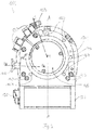
- Publication number
- EP3561306A1 EP3561306A1 EP18184605.6A EP18184605A EP3561306A1 EP 3561306 A1 EP3561306 A1 EP 3561306A1 EP 18184605 A EP18184605 A EP 18184605A EP 3561306 A1 EP3561306 A1 EP 3561306A1
- Authority
- EP
- European Patent Office
- Prior art keywords
- vacuum pump
- shielding means
- pump
- shielding
- contact
- Prior art date
- Legal status (The legal status is an assumption and is not a legal conclusion. Google has not performed a legal analysis and makes no representation as to the accuracy of the status listed.)
- Granted
Links
Images



Classifications
-
- F—MECHANICAL ENGINEERING; LIGHTING; HEATING; WEAPONS; BLASTING
- F04—POSITIVE - DISPLACEMENT MACHINES FOR LIQUIDS; PUMPS FOR LIQUIDS OR ELASTIC FLUIDS
- F04D—NON-POSITIVE-DISPLACEMENT PUMPS
- F04D19/00—Axial-flow pumps
- F04D19/02—Multi-stage pumps
- F04D19/04—Multi-stage pumps specially adapted to the production of a high vacuum, e.g. molecular pumps
- F04D19/042—Turbomolecular vacuum pumps
-
- F—MECHANICAL ENGINEERING; LIGHTING; HEATING; WEAPONS; BLASTING
- F04—POSITIVE - DISPLACEMENT MACHINES FOR LIQUIDS; PUMPS FOR LIQUIDS OR ELASTIC FLUIDS
- F04D—NON-POSITIVE-DISPLACEMENT PUMPS
- F04D29/00—Details, component parts, or accessories
- F04D29/02—Selection of particular materials
- F04D29/023—Selection of particular materials especially adapted for elastic fluid pumps
-
- F—MECHANICAL ENGINEERING; LIGHTING; HEATING; WEAPONS; BLASTING
- F04—POSITIVE - DISPLACEMENT MACHINES FOR LIQUIDS; PUMPS FOR LIQUIDS OR ELASTIC FLUIDS
- F04D—NON-POSITIVE-DISPLACEMENT PUMPS
- F04D29/00—Details, component parts, or accessories
- F04D29/40—Casings; Connections of working fluid
- F04D29/52—Casings; Connections of working fluid for axial pumps
- F04D29/522—Casings; Connections of working fluid for axial pumps especially adapted for elastic fluid pumps
-
- F—MECHANICAL ENGINEERING; LIGHTING; HEATING; WEAPONS; BLASTING
- F04—POSITIVE - DISPLACEMENT MACHINES FOR LIQUIDS; PUMPS FOR LIQUIDS OR ELASTIC FLUIDS
- F04D—NON-POSITIVE-DISPLACEMENT PUMPS
- F04D29/00—Details, component parts, or accessories
- F04D29/60—Mounting; Assembling; Disassembling
- F04D29/601—Mounting; Assembling; Disassembling specially adapted for elastic fluid pumps
-
- F—MECHANICAL ENGINEERING; LIGHTING; HEATING; WEAPONS; BLASTING
- F04—POSITIVE - DISPLACEMENT MACHINES FOR LIQUIDS; PUMPS FOR LIQUIDS OR ELASTIC FLUIDS
- F04D—NON-POSITIVE-DISPLACEMENT PUMPS
- F04D29/00—Details, component parts, or accessories
- F04D29/70—Suction grids; Strainers; Dust separation; Cleaning
- F04D29/701—Suction grids; Strainers; Dust separation; Cleaning especially adapted for elastic fluid pumps
-
- F—MECHANICAL ENGINEERING; LIGHTING; HEATING; WEAPONS; BLASTING
- F05—INDEXING SCHEMES RELATING TO ENGINES OR PUMPS IN VARIOUS SUBCLASSES OF CLASSES F01-F04
- F05D—INDEXING SCHEME FOR ASPECTS RELATING TO NON-POSITIVE-DISPLACEMENT MACHINES OR ENGINES, GAS-TURBINES OR JET-PROPULSION PLANTS
- F05D2300/00—Materials; Properties thereof
- F05D2300/50—Intrinsic material properties or characteristics
Definitions
- the present invention relates to a vacuum pump, in particular turbomolecular pump.
- Vacuum pumps are used under different operating conditions.
- one of these conditions may include strong, alternating magnetic fields that adversely affect electronic control of the vacuum pump and may also enter the environment through the pump. This can e.g. when using vacuum pumps in conjunction with mass spectrometers or other recipients to be the case. This can be problematic especially in environments in which comparatively strict regulations or guidelines exist in this respect and relatively low limit values must be adhered to.
- a vacuum pump according to claim 1, and in particular in that at least one shielding means is provided, wherein the shielding means is formed on a housing portion for electromagnetic shielding of an interior of the pump relative to an exterior of the pump.
- the shielding means is formed on a housing portion for electromagnetic shielding of an interior of the pump relative to an exterior of the pump.
- the shielding means comprises a metallic material.
- the shielding means comprises copper and / or beryllium, which have particularly good shielding properties, in particular due to their electrical conductivity.
- the housing section is a first housing section, which comprises at least one interface for connecting the first housing section to a second housing section of the vacuum pump or to a connection component for the vacuum pump.
- the shielding means is provided at the interface.
- the connection component may for example form or comprise a recipient of the vacuum pump.
- the shielding means may e.g. be formed exclusively on the first housing portion or formed integrally with the first housing portion.
- the shielding means may comprise an EMC gasket.
- the shielding means may alternatively or additionally be formed as a sheet metal element, in particular comprising copper.
- a material overlap may be provided on the interface described above.
- the shielding means may comprise a, in particular metallic, coating for shielding.
- the shielding means may comprise, for example, a shielding tape, in particular adhesive tape, and / or a shielding film, for example a bag, which optionally encloses the pump substantially completely.
- the interface may have a surface structuring.
- a surface of the first housing portion may have a surface structure formed to engage a surface of the second housing portion or the terminal component.
- the shielding means comprises a conductive paste and / or a conductive elastomer, which advantageously comprises metallic particles.
- an O-ring or other elongate sealing element may be used e.g. be provided in the form of a sealing cord of basically any material with metallic particles as a shielding.
- the shielding means may comprise a plastic and / or in particular be easily deformable.
- the shielding means is formed as a grid on an inlet flange.
- the interior of the pump can be effectively shielded from an interior of a connected recipient, in which, for example, strong magnetic fields prevail.
- the shielding means may be formed as a grid on a discharge flange. Through the grid, the interior of the pump can also be on the vacuum technically necessary openings, such as inlet and discharge ports, which are relatively large can effectively shield against external electromagnetic influences.
- a further embodiment is characterized in that the shielding means has at least one contact element for electrically contacting the shielding means with the housing section.
- the contact element may be formed, for example, resilient.
- the shielding means may be held by the contact element or by a plurality of contact elements on the housing portion.
- the shielding means can be held by a restoring force exerted by at least one contact element, in particular on an inner surface of an inlet or ejection flange.
- At least two differently shaped contact elements are provided.
- one of the contact elements for holding the shielding means and another only for electrical contacting of the shielding means may be formed with the housing portion.
- a contact element can have, for example, either a holding function and a contacting function or merely a contacting function.
- the various contact elements extend in different directions, in particular enclose an angle of more than 45 ° or at least substantially perpendicular to each other.
- At least one contact element may extend at an angle of more than 45 ° or at least substantially perpendicular to a main surface of the shielding means.
- the shielding means has a plurality of sides and at least two contact elements, in particular a plurality of contact elements, are provided on each side. In this way it can be ensured that several, in particular many, contact points formed by the contact elements between the shielding means and the housing section are present during operation, whereby the shielding is further improved. For example, more than four, in particular more than eight, contact elements can be provided on the shielding means, which in particular also hold the shielding means on the housing section.
- the shielding means may alternatively or additionally be arranged in a recess of the housing section and / or be substantially planar in shape.
- the shielding means can thus be attached to the housing section and / or secured in a space-saving manner.
- the shielding means has a shielding region and a contact region, wherein the contact region has a plurality of contact elements which are spaced apart from one another and project from the shielding region for contacting the shielding means with the housing section.
- the shielding area can thereby be optimized with regard to its shielding function.
- the shielding is particularly easy to manufacture and assemble when the shielding is formed in one piece.
- the shielding means can be produced by etching, stamping and / or laser cutting.
- the shielding means may also be a bent part.
- turbomolecular pump 111 comprises a pump inlet 115 surrounded by an inlet flange 113, to which in a conventional manner, a non-illustrated recipient can be connected.
- the gas from the recipient may be drawn from the recipient via the pump inlet 115 and conveyed through the pump to a pump outlet 117 to which a backing pump, such as a rotary vane pump, may be connected.
- the inlet flange 113 forms according to the orientation of the vacuum pump Fig. 1 the upper end of the housing 119 of the vacuum pump 111.
- the housing 119 comprises a lower part 121, on which an electronics housing 123 is arranged laterally.
- Housed in the electronics housing 123 are electrical and / or electronic components of the vacuum pump 111, eg for operating an electric motor 125 arranged in the vacuum pump.
- a plurality of connections 127 for accessories are provided on the electronics housing 123.
- a data interface 129 for example, according to the RS485 standard, and a power supply terminal 131 on the electronics housing 123 are arranged.
- a flood inlet 133 On the housing 119 of the turbomolecular pump 111, a flood inlet 133, in particular in the form of a flood valve, is provided, via which the vacuum pump 111 can be flooded.
- a sealing gas connection 135, which is also referred to as flushing gas connection is furthermore arranged, via which flushing gas for protecting the electric motor 125 (see, for example, US Pat Fig. 3 ) can be brought before the pumped by the pump gas in the engine compartment 137, in which the electric motor 125 is housed in the vacuum pump 111.
- two coolant connections 139 are further arranged, wherein one of the coolant connections is provided as an inlet and the other coolant connection as an outlet for coolant, which can be passed for cooling purposes in the vacuum pump.
- the lower side 141 of the vacuum pump can serve as a base, so that the vacuum pump 111 can be operated standing on the bottom 141.
- the vacuum pump 111 can also be fastened to a recipient via the inlet flange 113 and thus be operated to a certain extent suspended.
- the vacuum pump 111 may be configured to operate can be taken if it is oriented in a different way than in Fig. 1 is shown.
- Embodiments of the vacuum pump can also be implemented in which the lower side 141 can not be turned down but can be turned to the side or directed upwards.
- a bearing cap 145 is attached to the bottom 141.
- mounting holes 147 are arranged, via which the pump 111 can be attached, for example, to a support surface.
- a coolant line 148 is shown, in which the coolant introduced and discharged via the coolant connections 139 can circulate.
- the vacuum pump comprises a plurality of process gas pumping stages for conveying the process gas pending at the pump inlet 115 to the pump outlet 117.
- a rotor 149 is arranged, which has a about a rotation axis 151 rotatable rotor shaft 153.
- Turbomolecular pump 111 includes a plurality of turbomolecular pumping stages connected to each other in pumping action with a plurality of radial rotor disks 155 fixed to rotor shaft 153 and stator disks 157 arranged between rotor disks 155 and fixed in housing 119.
- a rotor disk 155 and an adjacent stator disk 157 each form one turbomolecular pumping stage.
- the stator disks 157 are held by spacer rings 159 at a desired axial distance from each other.
- the vacuum pump further comprises Holweck pumping stages which are arranged one inside the other in the radial direction and which are pumpingly connected to one another in series.
- the rotor of the Holweck pump stages comprises a rotor hub 161 arranged on the rotor shaft 153 and two cylinder shell-shaped Holweck rotor sleeves 163, 165 fastened to the rotor hub 161 and oriented coaxially with the rotation axis 151 and nested in the radial direction.
- two cylinder jacket-shaped Holweck stator sleeves 167, 169 are provided, which are also oriented coaxially to the rotation axis 151 and, as seen in the radial direction, are nested one inside the other.
- the pump-active surfaces of the Holweck pump stages are formed by the lateral surfaces, ie by the radial inner and / or outer surfaces, the Holweck rotor sleeves 163, 165 and the Holweck stator sleeves 167, 169.
- the radially inner surface of the outer Holweck stator sleeve 167 faces the radially outer surface of the outer Holweck rotor sleeve 163, forming a radial Holweck gap 171, and forms with it the first Holweck pump stage subsequent to the turbomolecular pumps.
- the radially inner surface of the outer Holweck rotor sleeve 163 faces the radially outer surface of the inner Holweck stator sleeve 169 forming a radial Holweck gap 173 and forms with this a second Holweck pumping stage.
- the radially inner surface of the inner Holweck stator sleeve 169 faces the radially outer surface of the inner Holweck rotor sleeve 165 to form a radial Holweck gap 175 and forms with this the third Holweck pumping stage.
- a radially extending channel may be provided, via which the radially outer Holweck gap 171 is connected to the middle Holweck gap 173.
- a radially extending channel may be provided at the top of the inner Holweck stator sleeve 169 , via which the middle Holweck gap 173 is connected to the radially inner Holweck gap 175.
- a connecting channel 179 to the outlet 117 may be provided at the lower end of the radially inner Holweck rotor sleeve 165.
- the above-mentioned pump-active surfaces of the Holweck stator sleeves 163, 165 each have a plurality of Holweck grooves running around the axis of rotation 151 in the axial direction, while the opposite lateral surfaces of the Holweck rotor sleeves 163, 165 are smooth and the gas for operating the Drive vacuum pump 111 in the Holweck grooves.
- a roller bearing 181 in the region of the pump outlet 117 and a permanent magnet bearing 183 in the region of the pump inlet 115 are provided.
- a conical spray nut 185 with an outer diameter increasing toward the rolling bearing 181 is provided on the rotor shaft 153.
- the spray nut 185 is in sliding contact with at least one scraper of a resource storage.
- the resource storage comprises a plurality of stackable absorbent discs 187 provided with a rolling bearing bearing means 181, e.g. with a lubricant, soaked.
- the operating means is transferred by capillary action of the resource storage on the scraper on the rotating sprayer nut 185 and due to the centrifugal force along the sprayer 185 in the direction of increasing outer diameter of the spray nut 185 to the roller bearing 181 out promoted, where eg fulfills a lubricating function.
- the rolling bearing 181 and the resource storage are enclosed by a trough-shaped insert 189 and the bearing cap 145 in the vacuum pump.
- the permanent magnet bearing 183 includes a rotor-side bearing half 191 and a stator-side bearing half 193, each comprising a ring stack of a plurality of stacked in the axial direction of permanent magnetic rings 195, 197 include.
- the ring magnets 195, 197 are opposed to each other to form a radial bearing gap 199, wherein the rotor-side ring magnets 195 are disposed radially outward and the stator-side ring magnets 197 radially inward.
- the magnetic field present in the bearing gap 199 causes magnetic repulsive forces between the ring magnets 195, 197, which cause a radial bearing of the rotor shaft 153.
- the rotor-side ring magnets 195 are supported by a carrier section 201 of the rotor shaft 153, which surrounds the ring magnets 195 radially on the outside.
- the stator-side ring magnets 197 are supported by a stator-side support portion 203, which extends through the ring magnets 197 and is suspended on radial struts 205 of the housing 119.
- Parallel to the axis of rotation 151, the rotor-side ring magnets 195 are fixed by a lid element 207 coupled to the carrier section 203.
- the stator-side ring magnets 197 are fixed parallel to the axis of rotation 151 in one direction by a fastening ring 209 connected to the carrier section 203 and a fastening ring 211 connected to the carrier section 203. Between the fastening ring 211 and the ring magnet 197, a plate spring 213 may also be provided.
- an emergency bearing 215 which runs empty in the normal operation of the vacuum pump 111 without contact and engages only with an excessive radial deflection of the rotor 149 relative to the stator to a radial stop for the rotor 149th to form, since a collision of the rotor-side structures with the stator-side structures prevented becomes.
- the safety bearing 215 is designed as an unlubricated rolling bearing and forms with the rotor 149 and / or the stator a radial gap, which causes the safety bearing 215 is disengaged in the normal pumping operation.
- the radial deflection at which the safety bearing 215 engages is dimensioned large enough so that the safety bearing 215 does not engage during normal operation of the vacuum pump, and at the same time small enough so that a collision of the rotor-side structures with the stator-side structures under all circumstances is prevented.
- the vacuum pump 111 includes the electric motor 125 for rotationally driving the rotor 149.
- the armature of the electric motor 125 is formed by the rotor 149 whose rotor shaft 153 extends through the motor stator 217.
- On the extending through the motor stator 217 through portion of the rotor shaft 153 may be arranged radially outside or embedded a permanent magnet arrangement.
- a gap 219 is arranged, which comprises a radial motor gap, via which the motor stator 217 and the permanent magnet arrangement for the transmission of the drive torque can influence magnetically.
- the motor stator 217 is fixed in the housing within the motor space 137 provided for the electric motor 125.
- a sealing gas which is also referred to as purge gas, and which may be, for example, air or nitrogen, enter the engine compartment 137.
- the electric motor 125 can be protected from the process gas, for example from corrosive components of the process gas, via the sealing gas.
- the engine compartment 137 can also be evacuated via the pump outlet 117, ie in the engine compartment 137 there is at least approximately the vacuum pressure caused by the backing pump connected to the pump outlet 117.
- delimiting wall 221 Between the rotor hub 161 and a motor space 137 delimiting wall 221 may also be a so-called. And per se known labyrinth seal 223 may be provided, in particular to achieve a better seal of the engine compartment 217 against the Holweck pump stages located radially outside.
- a vacuum pump according to the invention can have any desired combination of features of the above-described vacuum pump.
- a vacuum pump 10 according to the invention is shown with a housing section, which is designed as a so-called split-flow turbomolecular pump.
- the vacuum pump 10 has an inlet flange 12 with two inlets 16.
- the two inlets 16 can be connected via the flange 12 with different spaces of a recipient, for example in the form of a mass spectrometer.
- the inlet flange 12 forms an interface for connecting the housing section of the vacuum pump 10 with this recipient or, alternatively, for example also with two receptacles.
- both inlets 16 each designed as a grid 20 shielding is arranged.
- a respective grid 20 is of a planar shape and shields an interior of the pump 10 from an interior of the recipient (s).
- Fig. 7 is the right lattice 20 of the Fig. 6 shown enlarged.
- the grid 20 comprises a grid structure 26, which is formed as a honeycomb structure. However, another lattice structure, for example a rectangular structure, may also be provided.
- the grid structure 26 is surrounded by an edge 28 from which a plurality of contact elements 22 and 24 extends. The contact elements 22 and 24 each form an electrical contact of the grid 20 with an inner wall 14 of the inlet flange 12.
- the grid 20 has a shielding area and a contact area, wherein the contact elements 22 and 24 are provided in the contact area formed in the grid 20 from the edge area thereof.
- the contact elements 22 and 24 are spaced apart and are for contacting the grid 20 with the housing portion of the shielding from.
- the grid 20 is integrally formed.
- Various contact elements are provided, namely a set of contact elements 22 and a set of contact elements 24.
- the contact element 22 is formed as a tab or tongue which extends from the edge 28 substantially perpendicular to a major surface of the grid 20.
- the contact elements 22 are arranged in rows, wherein the contact elements 22 of a row extend parallel to one another and have a constant distance to each other over the row.
- the grid 20 is formed of a metallic material and a respective contact element 22 is formed by bending in the in Fig. 7 shown alignment brought.
- the contact element 22 is designed such that it exerts a restoring force in the direction of the inner wall 14 and thus electrically contacts the grid on the one hand with this inner wall 14 and on the other holds frictionally on this inner wall 14. All contact elements 22 together cause a sufficiently high holding force to hold the grid 20 in the inlet 16. Since the contact elements 22 are independently deflectable relative to the main surface of the grid 20, the grid 20 may be to any tolerances with respect to the dimensions of the inlet 16 forming opening or respect the course of the inner wall 14 delimiting this opening, with which the contact elements 22 cooperate, adapt.
- a respective contact element 24, which is comparatively small, is also resiliently formed, as a tab or tongue, extending from the edge 28 substantially parallel to the major surface of the grid 20 and substantially perpendicular to the inner wall 14.
- These contact elements 24 are provided only in respective corner regions of the inlet flange 16 and the grid 20, wherein the inner wall 14 has a radius in a respective corner region.
- the grid 20 is recessed in the respective corner areas, wherein the contact elements 24 have stopped.
- the contact elements 24 of a corner region thus extend substantially in one plane, but are not parallel to each other, but extend in respective directions, which preferably intersect at a radius center.
- the contact elements 24 are each dimensioned so long that they at an onset of the grid 20 - Fig. 7 from above - are bent by the inner wall 14 relative to the main surface of the grid 20 upwards and ensure contact with the inner wall 14 by the resulting restoring force.
- This pump according to the invention may be provided with further shielding means, as described for example in the introduction part.
Landscapes
- Engineering & Computer Science (AREA)
- Mechanical Engineering (AREA)
- General Engineering & Computer Science (AREA)
- Non-Positive Displacement Air Blowers (AREA)
Abstract
Description
- Die vorliegende Erfindung betrifft eine Vakuumpumpe, insbesondere Turbomolekularpumpe.
- Vakuumpumpen werden unter unterschiedlichen Betriebsbedingungen eingesetzt. Eine dieser Bedingungen kann beispielsweise starke, alternierende Magnetfelder umfassen, die eine elektronische Steuerung der Vakuumpumpe negativ beeinflussen und auch durch die Pumpe hindurch in die Umgebung gelangen können. Dies kann z.B. bei einem Einsatz von Vakuumpumpen in Verbindung mit Massenspektrometern oder anderen Rezipienten der Fall sein. Problematisch kann dies insbesondere in Umgebungen sein, in denen diesbezüglich vergleichsweise strenge Vorschriften bzw. Richtlinien existieren und relativ niedrige Grenzwerte eingehalten werden müssen.
- Es ist eine Aufgabe der Erfindung, bei einer Vakuumpumpe der eingangs genannten Art deren Funktionsfähigkeit sowie eine Nichtbeeinträchtigung der Umgebung auch unter Einfluss von insbesondere starken elektrischen und/oder magnetischen Feldern zu gewährleisten.
- Diese Aufgabe wird durch eine Vakuumpumpe nach Anspruch 1 gelöst, und insbesondere dadurch, dass zumindest ein Abschirmmittel vorgesehen ist, wobei das Abschirmmittel an einem Gehäuseabschnitt zur elektromagnetischen Abschirmung eines Inneren der Pumpe gegenüber einem Äußeren der Pumpe ausgebildet ist. Hierdurch wird sichergestellt, dass elektrische und/oder magnetische Felder, welche außerhalb der Vakuumpumpe auftreten, den Betrieb der Vakuumpumpe nicht stören und die Umgebung nicht beeinträchtigen können. Außerdem werden auch elektrische und/oder magnetische Felder, die möglicherweise innerhalb der Vakuumpumpe auftreten können, wirksam abgeschirmt, so dass elektronische Funktionselemente außerhalb der Pumpe durch diese Felder in ihrer Funktion nicht gestört werden.
- Bei einer Ausführungsform umfasst das Abschirmmittel ein metallisches Material. Hierdurch kann die Wirksamkeit der Abschirmung verbessert werden. Bei einer weiteren Ausführungsform umfasst das Abschirmmittel Kupfer und/oder Beryllium, welche besonders gute Abschirmungseigenschaften insbesondere aufgrund ihrer elektrischen Leitfähigkeit aufweisen.
- Bei einer Weiterbildung ist der Gehäuseabschnitt ein erster Gehäuseabschnitt, der zumindest eine Schnittstelle zur Verbindung des ersten Gehäuseabschnitts mit einem zweiten Gehäuseabschnitt der Vakuumpumpe oder mit einer Anschlusskomponente für die Vakuumpumpe umfasst. Dabei ist das Abschirmmittel an der Schnittstelle vorgesehen. Die Anschlusskomponente kann beispielsweise einen Rezipienten der Vakuumpumpe bilden oder umfassen.
- Das Abschirmmittel kann z.B. ausschließlich an dem ersten Gehäuseabschnitt ausgebildet oder einstückig mit dem ersten Gehäuseabschnitt ausgebildet sein.
- Das Abschirmmittel kann eine EMV-Dichtung umfassen. Hierdurch lassen sich große elektrische Kontaktflächen und somit eine besonders gute Abschirmung realisieren. Das Abschirmmittel kann alternativ oder zusätzlich als ein Blechelement, insbesondere umfassend Kupfer, ausgebildet sein. Auch kann eine Materialüberlappung an der vorstehend beschriebenen Schnittstelle vorgesehen sein. Vorteilhafterweise kann an der Schnittstelle keine Spielpassung, insbesondere eine Übergangs- oder Übermaßpassung vorgesehen sein, d.h. durch die Erfindung kann eine solche Spiel- bzw. Übergangs- oder Übermaßpassung gezielt verhindert oder reduziert werden. Hierdurch wird die Abschirmwirkung weiter verbessert.
- Alternativ oder zusätzlich kann das Abschirmmittel eine, insbesondere metallische, Beschichtung zur Abschirmung aufweisen. Das Abschirmmittel kann beispielsweise ein Abschirmband, insbesondere Klebeband, und/oder eine Abschirmfolie umfassen, beispielsweise einen Beutel, der optional die Pumpe im Wesentlichen vollständig umschließt.
- Die Schnittstelle kann eine Oberflächenstrukturierung aufweisen. Insbesondere kann eine Oberfläche des ersten Gehäuseabschnitts eine Oberflächenstruktur aufweisen, die zum Eingriff mit einer Oberfläche des zweiten Gehäuseabschnitts oder der Anschlusskomponente ausgebildet ist.
- Bei einer weiteren Ausführungsform umfasst das Abschirmmittel eine leitfähige Paste und/oder ein leitfähiges Elastomer, die bzw. das vorteilhafterweise metallische Partikel aufweist. Insbesondere kann ein O-Ring oder ein anderes langgestrecktes Dichtelement z.B. in Form einer Dichtschnur aus grundsätzlich beliebigem Material mit metallischen Partikeln als Abschirmmittel vorgesehen sein. Allgemein kann das Abschirmmittel einen Kunststoff umfassen und/oder insbesondere leicht verformbar sein.
- Bei einer Weiterbildung ist das Abschirmmittel als Gitter an einem Einlassflansch ausgebildet. Hierdurch kann das Innere der Pumpe wirksam gegenüber einem Inneren eines angeschlossenen Rezipienten, in welchem beispielsweise starke Magnetfelder herrschen, abgeschirmt werden. Alternativ oder zusätzlich kann das Abschirmmittel als Gitter an einem Ausstoßflansch ausgebildet sein. Durch das Gitter lässt sich das Innere der Pumpe auch an den vakuumtechnisch notwendigen Öffnungen, wie Einlass- und Ausstoßöffnungen, die vergleichsweise groß sein können, gegenüber äußeren elektromagnetischen Einflüssen wirksam abschirmen.
- Eine weitere Ausführungsform zeichnet sich dadurch aus, dass das Abschirmmittel zumindest ein Kontaktelement zur elektrischen Kontaktierung des Abschirmmittels mit dem Gehäuseabschnitt aufweist. Das Kontaktelement kann beispielsweise rückstellfähig ausgebildet sein. Insbesondere kann das Abschirmmittel durch das Kontaktelement oder durch eine Mehrzahl von Kontaktelementen an dem Gehäuseabschnitt gehalten sein. Somit sind insbesondere keine zusätzlichen Befestigungsmittel zum Festlegen des Abschirmmittels notwendig. Vorteilhafterweise kann das Abschirmmittel durch eine von zumindest einem Kontaktelement ausgeübte Rückstellkraft gehalten sein, insbesondere an einer Innenfläche eines Einlass- oder Ausstoßflansches.
- Bei einer weiteren Ausführungsform sind zumindest zwei verschieden ausgebildete Kontaktelemente vorgesehen. Beispielsweise kann eines der Kontaktelemente zum Halten des Abschirmmittels und ein anderes lediglich zur elektrischen Kontaktierung des Abschirmmittels mit dem Gehäuseabschnitt ausgebildet sein. Grundsätzlich kann ein Kontaktelement beispielsweise entweder eine Haltefunktion und eine Kontaktierungsfunktion oder lediglich eine Kontaktierungsfunktion aufweisen.
- Auch kann mit Vorteil vorgesehen sein, dass sich die verschiedenen Kontaktelemente in unterschiedliche Richtungen erstrecken, insbesondere einen Winkel von mehr als 45° einschließen oder zumindest im Wesentlichen senkrecht zueinander verlaufen.
- Alternativ oder zusätzlich kann sich zumindest ein Kontaktelement unter einem Winkel von mehr als 45° oder zumindest im Wesentlichen senkrecht zu einer Hauptfläche des Abschirmmittels erstrecken.
- Gemäß einer Ausführungsform weist das Abschirmmittel eine Mehrzahl von Seiten auf und an jeder Seite sind mindestens zwei Kontaktelemente, insbesondere eine Vielzahl von Kontaktelementen, vorgesehen. Hierdurch kann sichergestellt werden, dass mehrere, insbesondere viele, durch die Kontaktelemente gebildete Kontaktpunkte zwischen dem Abschirmmittel und dem Gehäuseabschnitt im Betrieb vorhanden sind, wodurch die Abschirmung weiter verbessert wird. An dem Abschirmmittel können beispielsweise mehr als vier, insbesondere mehr als acht, Kontaktelemente vorgesehen sein, welche insbesondere das Abschirmmittel auch an dem Gehäuseabschnitt halten.
- Das Abschirmmittel kann alternativ oder zusätzlich in einer Ausnehmung des Gehäuseabschnitts angeordnet sein und/oder im Wesentlichen von flächiger Gestalt sein. Das Abschirmmittelmittel lässt sich somit platzsparend an dem Gehäuseabschnitt anbringen und/oder befestigen.
- Bei einer Weiterbildung weist das Abschirmmittel einen Abschirmbereich und einen Kontaktbereich auf, wobei der Kontaktbereich eine Mehrzahl von Kontaktelementen aufweist, die voneinander beabstandet sind und zur Kontaktierung des Abschirmmittels mit dem Gehäuseabschnitt von dem Abschirmbereich abstehen. Der Abschirmbereich lässt sich dadurch hinsichtlich seiner Abschirmfunktion optimieren.
- Das Abschirmelement lässt sich besonders einfach fertigen und montieren, wenn das Abschirmmittel einteilig ausgebildet ist. Beispielsweise kann das Abschirmmittel durch Ätzen, Stanzen und/oder Laserschneiden hergestellt sein. Insbesondere kann das Abschirmmittel auch ein Biegeteil sein. Somit kann eine besonders einfache und kostengünstige Herstellung des Abschirmmittels realisiert werden. Weitere Ausführungsformen der Erfindung sind den Ansprüchen, der Beschreibung und den Figuren zu entnehmen.
- Nachfolgend wird die Erfindung beispielhaft anhand vorteilhafter Ausführungsformen unter Bezugnahme auf die beigefügten Figuren beschrieben. Es zeigen:
- Fig. 1
- eine perspektivische Ansicht einer Turbomolekularpumpe des Standes der Technik,
- Fig. 2
- eine Ansicht der Unterseite der Turbomolekularpumpe von
Fig. 1 , - Fig. 3
- einen Querschnitt der Turbomolekularpumpe längs der in
Fig. 2 gezeigten Schnittlinie A-A, - Fig. 4
- eine Querschnittsansicht der Turbomolekularpumpe längs der in
Fig. 2 gezeigten Schnittlinie B-B, - Fig. 5
- eine Querschnittsansicht der Turbomolekularpumpe längs der in
Fig. 2 gezeigten Schnittlinie C-C, - Fig. 6
- eine perspektivische Detailansicht einer erfindungsgemäßen Vakuumpumpe
- Fig. 7
- eine vergrößerte Ansicht eines Ausschnitts der
Fig. 6 . - Die in
Fig. 1 gezeigte Turbomolekularpumpe 111 umfasst einen von einem Einlassflansch 113 umgebenen Pumpeneinlass 115, an welchen in an sich bekannter Weise ein nicht dargestellter Rezipient angeschlossen werden kann. Das Gas aus dem Rezipienten kann über den Pumpeneinlass 115 aus dem Rezipienten gesaugt und durch die Pumpe hindurch zu einem Pumpenauslass 117 gefördert werden, an den eine Vorvakuumpumpe, wie etwa eine Drehschieberpumpe, angeschlossen sein kann. - Der Einlassflansch 113 bildet bei der Ausrichtung der Vakuumpumpe gemäß
Fig. 1 das obere Ende des Gehäuses 119 der Vakuumpumpe 111. Das Gehäuse 119 umfasst ein Unterteil 121, an welchem seitlich ein Elektronikgehäuse 123 angeordnet ist. In dem Elektronikgehäuse 123 sind elektrische und/oder elektronische Komponenten der Vakuumpumpe 111 untergebracht, z.B. zum Betreiben eines in der Vakuumpumpe angeordneten Elektromotors 125. Am Elektronikgehäuse 123 sind mehrere Anschlüsse 127 für Zubehör vorgesehen. Außerdem sind eine Datenschnittstelle 129, z.B. gemäß dem RS485-Standard, und ein Stromversorgungsanschluss 131 am Elektronikgehäuse 123 angeordnet. - Am Gehäuse 119 der Turbomolekularpumpe 111 ist ein Fluteinlass 133, insbesondere in Form eines Flutventils, vorgesehen, über den die Vakuumpumpe 111 geflutet werden kann. Im Bereich des Unterteils 121 ist ferner noch ein Sperrgasanschluss 135, der auch als Spülgasanschluss bezeichnet wird, angeordnet, über welchen Spülgas zum Schutz des Elektromotors 125 (siehe z.B.
Fig. 3 ) vor dem von der Pumpe geförderten Gas in den Motorraum 137, in welchem der Elektromotor 125 in der Vakuumpumpe 111 untergebracht ist, gebracht werden kann. Im Unterteil 121 sind ferner noch zwei Kühlmittelanschlüsse 139 angeordnet, wobei einer der Kühlmittelanschlüsse als Einlass und der andere Kühlmittelanschluss als Auslass für Kühlmittel vorgesehen ist, das zu Kühlzwecken in die Vakuumpumpe geleitet werden kann. - Die untere Seite 141 der Vakuumpumpe kann als Standfläche dienen, sodass die Vakuumpumpe 111 auf der Unterseite 141 stehend betrieben werden kann. Die Vakuumpumpe 111 kann aber auch über den Einlassflansch 113 an einem Rezipienten befestigt werden und somit gewissermaßen hängend betrieben werden. Außerdem kann die Vakuumpumpe 111 so gestaltet sein, dass sie auch in Betrieb genommen werden kann, wenn sie auf andere Weise ausgerichtet ist als in
Fig. 1 gezeigt ist. Es lassen sich auch Ausführungsformen der Vakuumpumpe realisieren, bei der die Unterseite 141 nicht nach unten, sondern zur Seite gewandt oder nach oben gerichtet angeordnet werden kann. - An der Unterseite 141, die in
Fig. 2 dargestellt ist, sind noch diverse Schrauben 143 angeordnet, mittels denen hier nicht weiter spezifizierte Bauteile der Vakuumpumpe aneinander befestigt sind. Beispielsweise ist ein Lagerdeckel 145 an der Unterseite 141 befestigt. - An der Unterseite 141 sind außerdem Befestigungsbohrungen 147 angeordnet, über welche die Pumpe 111 beispielsweise an einer Auflagefläche befestigt werden kann.
- In den
Figuren 2 bis 5 ist eine Kühlmittelleitung 148 dargestellt, in welcher das über die Kühlmittelanschlüsse 139 ein- und ausgeleitete Kühlmittel zirkulieren kann. - Wie die Schnittdarstellungen der
Figuren 3 bis 5 zeigen, umfasst die Vakuumpumpe mehrere Prozessgaspumpstufen zur Förderung des an dem Pumpeneinlass 115 anstehenden Prozessgases zu dem Pumpenauslass 117. - In dem Gehäuse 119 ist ein Rotor 149 angeordnet, der eine um eine Rotationsachse 151 drehbare Rotorwelle 153 aufweist.
- Die Turbomolekularpumpe 111 umfasst mehrere pumpwirksam miteinander in Serie geschaltete turbomolekulare Pumpstufen mit mehreren an der Rotorwelle 153 befestigten radialen Rotorscheiben 155 und zwischen den Rotorscheiben 155 angeordneten und in dem Gehäuse 119 festgelegten Statorscheiben 157. Dabei bilden eine Rotorscheibe 155 und eine benachbarte Statorscheibe 157 jeweils eine turbomolekulare Pumpstufe. Die Statorscheiben 157 sind durch Abstandsringe 159 in einem gewünschten axialen Abstand zueinander gehalten.
- Die Vakuumpumpe umfasst außerdem in radialer Richtung ineinander angeordnete und pumpwirksam miteinander in Serie geschaltete Holweck-Pumpstufen. Der Rotor der Holweck-Pumpstufen umfasst eine an der Rotorwelle 153 angeordnete Rotornabe 161 und zwei an der Rotornabe 161 befestigte und von dieser getragene zylindermantelförmige Holweck-Rotorhülsen 163, 165, die koaxial zur Rotationsachse 151 orientiert und in radialer Richtung ineinander geschachtelt sind. Ferner sind zwei zylindermantelförmige Holweck-Statorhülsen 167, 169 vorgesehen, die ebenfalls koaxial zu der Rotationsachse 151 orientiert und in radialer Richtung gesehen ineinander geschachtelt sind.
- Die pumpaktiven Oberflächen der Holweck-Pumpstufen sind durch die Mantelflächen, also durch die radialen Innen- und/oder Außenflächen, der Holweck-Rotorhülsen 163, 165 und der Holweck-Statorhülsen 167, 169 gebildet. Die radiale Innenfläche der äußeren Holweck-Statorhülse 167 liegt der radialen Außenfläche der äußeren Holweck-Rotorhülse 163 unter Ausbildung eines radialen Holweck-Spalts 171 gegenüber und bildet mit dieser die der Turbomolekularpumpen nachfolgende erste Holweck-Pumpstufe. Die radiale Innenfläche der äußeren Holweck-Rotorhülse 163 steht der radialen Außenfläche der inneren Holweck-Statorhülse 169 unter Ausbildung eines radialen Holweck-Spalts 173 gegenüber und bildet mit dieser eine zweite Holweck-Pumpstufe. Die radiale Innenfläche der inneren Holweck-Statorhülse 169 liegt der radialen Außenfläche der inneren Holweck-Rotorhülse 165 unter Ausbildung eines radialen Holweck-Spalts 175 gegenüber und bildet mit dieser die dritte Holweck-Pumpstufe.
- Am unteren Ende der Holweck-Rotorhülse 163 kann ein radial verlaufender Kanal vorgesehen sein, über den der radial außenliegende Holweck-Spalt 171 mit dem mittleren Holweck-Spalt 173 verbunden ist. Außerdem kann am oberen Ende der inneren Holweck-Statorhülse 169 ein radial verlaufender Kanal vorgesehen sein, über den der mittlere Holweck-Spalt 173 mit dem radial innenliegenden Holweck-Spalt 175 verbunden ist. Dadurch werden die ineinander geschachtelten Holweck-Pumpstufen in Serie miteinander geschaltet. Am unteren Ende der radial innenliegenden Holweck-Rotorhülse 165 kann ferner ein Verbindungskanal 179 zum Auslass 117 vorgesehen sein.
- Die vorstehend genannten pumpaktiven Oberflächen der Holweck-Statorhülsen 163, 165 weisen jeweils mehrere spiralförmig um die Rotationsachse 151 herum in axialer Richtung verlaufende Holweck-Nuten auf, während die gegenüberliegenden Mantelflächen der Holweck-Rotorhülsen 163, 165 glatt ausgebildet sind und das Gas zum Betrieb der Vakuumpumpe 111 in den Holweck-Nuten vorantreiben.
- Zur drehbaren Lagerung der Rotorwelle 153 sind ein Wälzlager 181 im Bereich des Pumpenauslasses 117 und ein Permanentmagnetlager 183 im Bereich des Pumpeneinlasses 115 vorgesehen.
- Im Bereich des Wälzlagers 181 ist an der Rotorwelle 153 eine konische Spritzmutter 185 mit einem zu dem Wälzlager 181 hin zunehmenden Außendurchmesser vorgesehen. Die Spritzmutter 185 steht mit mindestens einem Abstreifer eines Betriebsmittelspeichers in gleitendem Kontakt. Der Betriebsmittelspeicher umfasst mehrere aufeinander gestapelte saugfähige Scheiben 187, die mit einem Betriebsmittel für das Wälzlager 181, z.B. mit einem Schmiermittel, getränkt sind.
- Im Betrieb der Vakuumpumpe 111 wird das Betriebsmittel durch kapillare Wirkung von dem Betriebsmittelspeicher über den Abstreifer auf die rotierende Spritzmutter 185 übertragen und in Folge der Zentrifugalkraft entlang der Spritzmutter 185 in Richtung des größer werdenden Außendurchmessers der Spritzmutter 185 zu dem Wälzlager 181 hin gefördert, wo es z.B. eine schmierende Funktion erfüllt. Das Wälzlager 181 und der Betriebsmittelspeicher sind durch einen wannenförmigen Einsatz 189 und den Lagerdeckel 145 in der Vakuumpumpe eingefasst.
- Das Permanentmagnetlager 183 umfasst eine rotorseitige Lagerhälfte 191 und eine statorseitige Lagerhälfte 193, welche jeweils einen Ringstapel aus mehreren in axialer Richtung aufeinander gestapelten permanentmagnetischen Ringen 195, 197 umfassen. Die Ringmagnete 195, 197 liegen einander unter Ausbildung eines radialen Lagerspalts 199 gegenüber, wobei die rotorseitigen Ringmagnete 195 radial außen und die statorseitigen Ringmagnete 197 radial innen angeordnet sind. Das in dem Lagerspalt 199 vorhandene magnetische Feld ruft magnetische Abstoßungskräfte zwischen den Ringmagneten 195, 197 hervor, welche eine radiale Lagerung der Rotorwelle 153 bewirken. Die rotorseitigen Ringmagnete 195 sind von einem Trägerabschnitt 201 der Rotorwelle 153 getragen, welcher die Ringmagnete 195 radial außenseitig umgibt. Die statorseitigen Ringmagnete 197 sind von einem statorseitigen Trägerabschnitt 203 getragen, welcher sich durch die Ringmagnete 197 hindurch erstreckt und an radialen Streben 205 des Gehäuses 119 aufgehängt ist. Parallel zu der Rotationsachse 151 sind die rotorseitigen Ringmagnete 195 durch ein mit dem Trägerabschnitt 203 gekoppeltes Deckelelement 207 festgelegt. Die statorseitigen Ringmagnete 197 sind parallel zu der Rotationsachse 151 in der einen Richtung durch einen mit dem Trägerabschnitt 203 verbundenen Befestigungsring 209 sowie einen mit dem Trägerabschnitt 203 verbundenen Befestigungsring 211 festgelegt. Zwischen dem Befestigungsring 211 und den Ringmagneten 197 kann außerdem eine Tellerfeder 213 vorgesehen sein.
- Innerhalb des Magnetlagers ist ein Not- bzw. Fanglager 215 vorgesehen, welches im normalen Betrieb der Vakuumpumpe 111 ohne Berührung leer läuft und erst bei einer übermäßigen radialen Auslenkung des Rotors 149 relativ zu dem Stator in Eingriff gelangt, um einen radialen Anschlag für den Rotor 149 zu bilden, da eine Kollision der rotorseitigen Strukturen mit den statorseitigen Strukturen verhindert wird. Das Fanglager 215 ist als ungeschmiertes Wälzlager ausgebildet und bildet mit dem Rotor 149 und/oder dem Stator einen radialen Spalt, welcher bewirkt, dass das Fanglager 215 im normalen Pumpbetrieb außer Eingriff ist. Die radiale Auslenkung, bei der das Fanglager 215 in Eingriff gelangt, ist groß genug bemessen, sodass das Fanglager 215 im normalen Betrieb der Vakuumpumpe nicht in Eingriff gelangt, und gleichzeitig klein genug, sodass eine Kollision der rotorseitigen Strukturen mit den statorseitigen Strukturen unter allen Umständen verhindert wird.
- Die Vakuumpumpe 111 umfasst den Elektromotor 125 zum drehenden Antreiben des Rotors 149. Der Anker des Elektromotors 125 ist durch den Rotor 149 gebildet, dessen Rotorwelle 153 sich durch den Motorstator 217 hindurch erstreckt. Auf den sich durch den Motorstator 217 hindurch erstreckenden Abschnitt der Rotorwelle 153 kann radial außenseitig oder eingebettet eine Permanentmagnetanordnung angeordnet sein. Zwischen dem Motorstator 217 und dem sich durch den Motorstator 217 hindurch erstreckenden Abschnitt des Rotors 149 ist ein Zwischenraum 219 angeordnet, welcher einen radialen Motorspalt umfasst, über den sich der Motorstator 217 und die Permanentmagnetanordnung zur Übertragung des Antriebsmoments magnetisch beeinflussen können.
- Der Motorstator 217 ist in dem Gehäuse innerhalb des für den Elektromotor 125 vorgesehenen Motorraums 137 festgelegt. Über den Sperrgasanschluss 135 kann ein Sperrgas, das auch als Spülgas bezeichnet wird, und bei dem es sich beispielsweise um Luft oder um Stickstoff handeln kann, in den Motorraum 137 gelangen. Über das Sperrgas kann der Elektromotor 125 vor Prozessgas, z.B. vor korrosiv wirkenden Anteilen des Prozessgases, geschützt werden. Der Motorraum 137 kann auch über den Pumpenauslass 117 evakuiert werden, d.h. im Motorraum 137 herrscht zumindest annäherungsweise der von der am Pumpenauslass 117 angeschlossenen Vorvakuumpumpe bewirkte Vakuumdruck.
- Zwischen der Rotornabe 161 und einer den Motorraum 137 begrenzenden Wandung 221 kann außerdem eine sog. und an sich bekannte Labyrinthdichtung 223 vorgesehen sein, insbesondere um eine bessere Abdichtung des Motorraums 217 gegenüber den radial außerhalb liegenden Holweck-Pumpstufen zu erreichen.
- Alle Merkmale der vorstehend beschriebenen Vakuumpumpe können auch bei der nachstehend beschriebenen erfindungsgemäßen Vakuumpumpe vorgesehen sein, d.h. eine erfindungsgemäße Vakuumpumpe kann grundsätzlich jede beliebige Kombination von Merkmalen der vorstehend beschriebenen Vakuumpumpe aufweisen.
- In
Fig. 6 ist eine erfindungsgemäße Vakuumpumpe 10 mit einem Gehäuseabschnitt gezeigt, welche als sogenannte Split-Flow-Turbomolekularpumpe ausgebildet ist. Die Vakuumpumpe 10 weist einen Einlassflansch 12 mit zwei Einlässen 16 auf. Die beiden Einlässe 16 können über den Flansch 12 mit unterschiedlichen Räumen eines Rezipienten z.B. in Form eines Massenspektrometers verbunden werden. Der Einlassflansch 12 bildet eine Schnittstelle zur Verbindung des Gehäuseabschnitts der Vakuumpumpe 10 mit diesem Rezipienten oder alternativ z.B. auch mit zwei Rezipienten. - In beiden Einlässen 16 ist jeweils ein als Gitter 20 ausgebildetes Abschirmmittel angeordnet. Ein jeweiliges Gitter 20 ist von flächiger Gestalt und schirmt ein Inneres der Pumpe 10 gegenüber einem Inneren des bzw. der Rezipienten ab.
- In
Fig. 7 ist das rechte Gitter 20 derFig. 6 vergrößert dargestellt. Das Gitter 20 umfasst eine Gitterstruktur 26, die als Wabenstruktur ausgebildet ist. Jedoch kann auch eine andere Gitterstruktur, beispielsweise eine Rechteckstruktur, vorgesehen sein. Die Gitterstruktur 26 ist von einem Rand 28 umgeben, von dem sich eine Vielzahl von Kontaktelementen 22 und 24 erstreckt. Die Kontaktelemente 22 und 24 bilden jeweils eine elektrische Kontaktierung des Gitters 20 mit einer Innenwand 14 des Einlassflansches 12. - Das Gitter 20 weist einen Abschirmbereich und einen Kontaktbereich auf, wobei in dem Kontaktbereich, der bei dem Gitter 20 von dessen Randbereich gebildet ist, die Kontaktelemente 22 und 24 vorgesehen sind. Die Kontaktelemente 22 und 24 sind voneinander beabstandet und stehen zur Kontaktierung des Gitters 20 mit dem Gehäuseabschnitt von dem Abschirmbereich ab. Das Gitter 20 ist einteilig ausgebildet. Es sind verschiedenartige Kontaktelemente vorgesehen, nämlich ein Satz von Kontaktelementen 22 und ein Satz von Kontaktelementen 24.
- Ein jeweiliges Kontaktelement 22, das vergleichsweise groß und laschen- oder zungenartig ausgebildet ist, gewährleistet nicht nur eine Kontaktierung, sondern dient auch dazu, das Gitter 20 in dem Einlass 16 zu halten. Das Kontaktelement 22 ist als eine Lasche oder Zunge ausgebildet, welche sich von dem Rand 28 im Wesentlichen senkrecht zu einer Hauptfläche des Gitters 20 erstreckt. Die Kontaktelemente 22 sind in Reihen angeordnet, wobei sich die Kontaktelemente 22 einer Reihe parallel zueinander erstrecken und zueinander einen über die Reihe konstanten Abstand aufweisen.
- Das Gitter 20 ist aus einem metallischen Material gebildet und ein jeweiliges Kontaktelement 22 ist durch Biegen in die in
Fig. 7 dargestellte Ausrichtung gebracht. Das Kontaktelement 22 ist derart ausgebildet, dass es eine Rückstellkraft in Richtung der Innenwand 14 ausübt und somit das Gitter zum einen mit dieser Innenwand 14 elektrisch kontaktiert und zum anderen an dieser Innenwand 14 reibschlüssig hält. Alle Kontaktelemente 22 bewirken zusammen eine ausreichend hohe Haltekraft, um das Gitter 20 in dem Einlass 16 zu halten. Da die Kontaktelemente 22 unabhängig voneinander relativ zur Hauptfläche des Gitters 20 auslenkbar sind, kann sich das Gitter 20 an gegebenenfalls vorhandene Toleranzen hinsichtlich der Abmessungen der den Einlass 16 bildenden Öffnung bzw. hinsichtlich des Verlaufs der diese Öffnung begrenzenden Innenwand 14, mit der die Kontaktelemente 22 zusammenwirken, anpassen. - Ein jeweiliges Kontaktelement 24, das vergleichsweise klein ist, ist ebenfalls rückstellfähig ausgebildet, und zwar als Lasche oder Zunge, die sich von dem Rand 28 im Wesentlichen parallel zu der Hauptfläche des Gitters 20 und im Wesentlichen senkrecht zur Innenwand 14 erstreckt. Diese Kontaktelemente 24 sind lediglich in jeweiligen Eckbereichen des Einlassflansches 16 bzw. des Gitters 20 vorgesehen, wobei die Innenwand 14 in einem jeweiligen Eckbereich einen Radius aufweist. Das Gitter 20 ist in den jeweiligen Eckbereichen ausgespart, wobei die Kontaktelemente 24 stehen geblieben sind. Die Kontaktelemente 24 eines Eckbereiches erstrecken sich somit im Wesentlichen in einer Ebene, sind jedoch nicht parallel zueinander, sondern erstrecken sich in jeweiligen Richtungen, die sich bevorzugt in einem Radiusmittelpunkt schneiden.
- Die Kontaktelemente 24 sind jeweils derart lang dimensioniert, dass sie bei einem Einsetzen des Gitters 20 - in
Fig. 7 von oben - durch die Innenwand 14 relativ zur Hauptfläche des Gitters 20 nach oben gebogen werden und durch die hieraus resultierende Rückstellkraft auf die Innenwand 14 eine Kontaktierung gewährleisten. - Diese erfindungsgemäße Pumpe kann mit weiteren Abschirmmitteln versehen sein, wie sie z.B. im Einleitungsteil beschrieben sind.
-
- 10
- Vakuumpumpe
- 12
- Einlassflansch
- 14
- Innenwand
- 16
- Einlass
- 20
- Gitter
- 22
- Kontaktelement
- 24
- Kontaktelement
- 26
- Gitterstruktur
- 28
- Rand
- 111
- Turbomolekularpumpe
- 113
- Einlassflansch
- 115
- Pumpeneinlass
- 117
- Pumpenauslass
- 119
- Gehäuse
- 121
- Unterteil
- 123
- Elektronikgehäuse
- 125
- Elektromotor
- 127
- Zubehöranschluss
- 129
- Datenschnittstelle
- 131
- Stromversorgungsanschluss
- 133
- Fluteinlass
- 135
- Sperrgasanschluss
- 137
- Motorraum
- 139
- Kühlmittelanschluss
- 141
- Unterseite
- 143
- Schraube
- 145
- Lagerdeckel
- 147
- Befestigungsbohrung
- 148
- Kühlmittelleitung
- 149
- Rotor
- 151
- Rotationsachse
- 153
- Rotorwelle
- 155
- Rotorscheibe
- 157
- Statorscheibe
- 159
- Abstandsring
- 161
- Rotornabe
- 163
- Holweck-Rotorhülse
- 165
- Holweck-Rotorhülse
- 167
- Holweck-Statorhülse
- 169
- Holweck-Statorhülse
- 171
- Holweck-Spalt
- 173
- Holweck-Spalt
- 175
- Holweck-Spalt
- 179
- Verbindungskanal
- 181
- Wälzlager
- 183
- Permanentmagnetlager
- 185
- Spritzmutter
- 187
- Scheibe
- 189
- Einsatz
- 191
- rotorseitige Lagerhälfte
- 193
- statorseitige Lagerhälfte
- 195
- Ringmagnet
- 197
- Ringmagnet
- 199
- Lagerspalt
- 201
- Trägerabschnitt
- 203
- Trägerabschnitt
- 205
- radiale Strebe
- 207
- Deckelelement
- 209
- Stützring
- 211
- Befestigungsring
- 213
- Tellerfeder
- 215
- Not- bzw. Fanglager
- 217
- Motorstator
- 219
- Zwischenraum
- 221
- Wandung
- 223
- Labyrinthdichtung
Claims (15)
- Vakuumpumpe (10), insbesondere Turbomolekularpumpe, mit zumindest einem Gehäuseabschnitt, und
zumindest einem Abschirmmittel (20),
wobei das Abschirmmittel (20) an dem Gehäuseabschnitt zur elektromagnetischen Abschirmung eines Inneren der Pumpe (10) gegenüber einem Äußeren der Pumpe (10) ausgebildet ist. - Vakuumpumpe (10) nach Anspruch 1,
dadurch gekennzeichnet, dass
das Abschirmmittel (20) ein metallisches Material umfasst. - Vakuumpumpe (10) nach Anspruch 1 oder 2,
dadurch gekennzeichnet, dass das Abschirmmittel (20) Kupfer und/oder Beryllium umfasst. - Vakuumpumpe (10) nach einem der vorhergehenden Ansprüche,
dadurch gekennzeichnet, dass
der Gehäuseabschnitt ein erster Gehäuseabschnitt ist und zumindest eine Schnittstelle zur Verbindung des ersten Gehäuseabschnitts mit einem zweiten Gehäuseabschnitt der Vakuumpumpe oder mit einer Anschlusskomponente für die Vakuumpumpe (10) umfasst, wobei das Abschirmmittel (20) an der Schnittstelle vorgesehen ist. - Vakuumpumpe (10) nach einem der vorhergehenden Ansprüche,
dadurch gekennzeichnet, dass
das Abschirmmittel als Gitter (20) an einem Einlassflansch (12) und/oder Ausstoßflansch ausgebildet ist. - Vakuumpumpe (10) nach einem der vorhergehenden Ansprüche,
dadurch gekennzeichnet, dass
das Abschirmmittel (20) zumindest ein Kontaktelement (22, 24) zur elektrischen Kontaktierung des Abschirmmittels (20) mit dem Gehäuseabschnitt aufweist. - Vakuumpumpe (10) nach Anspruch 6,
dadurch gekennzeichnet, dass
das Kontaktelement (22, 24) rückstellfähig ausgebildet ist. - Vakuumpumpe (10) nach Anspruch 6 oder 7,
dadurch gekennzeichnet, dass
das Abschirmmittel (20) durch das Kontaktelement oder durch eine Mehrzahl von Kontaktelementen (22) an dem Gehäuseabschnitt gehalten ist. - Vakuumpumpe (10) nach einem der Ansprüche 6 bis 8,
dadurch gekennzeichnet, dass
zumindest zwei verschieden ausgebildete Kontaktelemente (22, 24) vorgesehen sind. - Vakuumpumpe (10) nach Anspruch 9,
dadurch gekennzeichnet, dass
sich die verschiedenen Kontaktelemente (22, 24) in unterschiedliche Richtungen erstrecken, insbesondere einen Winkel von mehr als 45° einschließen oder zumindest im Wesentlichen senkrecht zueinander verlaufen. - Vakuumpumpe (10) nach einem der Ansprüche 6 bis 10,
dadurch gekennzeichnet, dass
sich zumindest ein Kontaktelement (22) unter einem Winkel von mehr als 45° oder zumindest im Wesentlichen senkrecht zu einer Hauptfläche des Abschirmmittels (20) erstreckt. - Vakuumpumpe (10) nach einem der vorhergehenden Ansprüche,
dadurch gekennzeichnet, dass
das Abschirmmittel (20) in einer Ausnehmung des Gehäuseabschnitts angeordnet ist. - Vakuumpumpe (10) nach einem der vorhergehenden Ansprüche,
dadurch gekennzeichnet, dass
das Abschirmmittel (20) im Wesentlichen von flächiger Gestalt ist. - Vakuumpumpe (10) nach einem der vorhergehenden Ansprüche,
dadurch gekennzeichnet, dass
das Abschirmmittel (20) einen Abschirmbereich und einen Kontaktbereich aufweist, der eine Mehrzahl von Kontaktelementen (22, 24) aufweist, die voneinander beabstandet sind und zur Kontaktierung des Abschirmmittels (20) mit dem Gehäuseabschnitt von dem Abschirmbereich abstehen. - Vakuumpumpe (10) nach einem der vorhergehenden Ansprüche,
dadurch gekennzeichnet, dass
das Abschirmmittel (20) einteilig ausgebildet ist.
Priority Applications (2)
| Application Number | Priority Date | Filing Date | Title |
|---|---|---|---|
| EP18184605.6A EP3561306B1 (de) | 2018-07-20 | 2018-07-20 | Vakuumpumpe |
| JP2019131612A JP2020012467A (ja) | 2018-07-20 | 2019-07-17 | 真空ポンプ |
Applications Claiming Priority (1)
| Application Number | Priority Date | Filing Date | Title |
|---|---|---|---|
| EP18184605.6A EP3561306B1 (de) | 2018-07-20 | 2018-07-20 | Vakuumpumpe |
Publications (2)
| Publication Number | Publication Date |
|---|---|
| EP3561306A1 true EP3561306A1 (de) | 2019-10-30 |
| EP3561306B1 EP3561306B1 (de) | 2021-06-09 |
Family
ID=63014344
Family Applications (1)
| Application Number | Title | Priority Date | Filing Date |
|---|---|---|---|
| EP18184605.6A Active EP3561306B1 (de) | 2018-07-20 | 2018-07-20 | Vakuumpumpe |
Country Status (2)
| Country | Link |
|---|---|
| EP (1) | EP3561306B1 (de) |
| JP (1) | JP2020012467A (de) |
Citations (3)
| Publication number | Priority date | Publication date | Assignee | Title |
|---|---|---|---|---|
| JP2005291040A (ja) * | 2004-03-31 | 2005-10-20 | Shimadzu Corp | ターボ分子ポンプ |
| US20130129482A1 (en) * | 2010-08-06 | 2013-05-23 | Shimadzu Corporation | Vacuum pump |
| EP3034881A1 (de) * | 2014-12-18 | 2016-06-22 | Pfeiffer Vacuum GmbH | Vakuumpumpe |
Family Cites Families (5)
| Publication number | Priority date | Publication date | Assignee | Title |
|---|---|---|---|---|
| US4384165A (en) * | 1981-09-14 | 1983-05-17 | Motorola, Inc. | Radio frequency shield with force multiplier interconnection fingers for an electromagnetic gasket |
| JP2006144783A (ja) * | 2004-11-24 | 2006-06-08 | Pfeiffer Vacuum Gmbh | 高速回転ロータを有する真空ポンプのフランジと結合可能な破損防止装置 |
| DE102005052792B4 (de) * | 2004-11-24 | 2017-12-14 | Pfeiffer Vacuum Gmbh | Splitterschutz für Vakuumpumpe mit schnelldrehendem Rotor |
| JP3119272U (ja) * | 2005-12-08 | 2006-02-16 | 株式会社島津製作所 | 分子ポンプ |
| CN103201520B (zh) * | 2010-11-24 | 2017-02-08 | 埃地沃兹日本有限公司 | 真空泵用的保护网和具备其的真空泵 |
-
2018
- 2018-07-20 EP EP18184605.6A patent/EP3561306B1/de active Active
-
2019
- 2019-07-17 JP JP2019131612A patent/JP2020012467A/ja active Pending
Patent Citations (3)
| Publication number | Priority date | Publication date | Assignee | Title |
|---|---|---|---|---|
| JP2005291040A (ja) * | 2004-03-31 | 2005-10-20 | Shimadzu Corp | ターボ分子ポンプ |
| US20130129482A1 (en) * | 2010-08-06 | 2013-05-23 | Shimadzu Corporation | Vacuum pump |
| EP3034881A1 (de) * | 2014-12-18 | 2016-06-22 | Pfeiffer Vacuum GmbH | Vakuumpumpe |
Also Published As
| Publication number | Publication date |
|---|---|
| JP2020012467A (ja) | 2020-01-23 |
| EP3561306B1 (de) | 2021-06-09 |
Similar Documents
| Publication | Publication Date | Title |
|---|---|---|
| EP3657021B1 (de) | Vakuumpumpe | |
| EP2829734B1 (de) | Vakuumpumpe | |
| EP4108932A1 (de) | Rezipient und hochvakuumpumpe | |
| DE102008062679A1 (de) | Fluiddynamisches Lagersystem | |
| DE102007044945A1 (de) | Vakuumpumpe | |
| EP3670924B1 (de) | Vakuumpumpe und verfahren zur herstellung einer solchen | |
| EP3851680A1 (de) | Molekularvakuumpumpe und verfahren zum beeinflussen des saugvermögens einer solchen | |
| EP3318763B1 (de) | Vakuumdichtung, doppeldichtung, vakuumsystem und vakuumpumpe | |
| EP3385961A1 (de) | Monolithischer permanentmagnet | |
| EP3561306B1 (de) | Vakuumpumpe | |
| EP3327293B1 (de) | Vakuumpumpe mit mehreren einlässen | |
| EP3135932B2 (de) | Vakuumpumpe und permanentmagnetlager | |
| EP3926175A1 (de) | Vakuumpumpe mit wälzlager | |
| EP4325061B1 (de) | Turbomolekularvakuumpumpe | |
| EP4194700B1 (de) | Vakuumpumpe mit einer holweck-pumpstufe mit veränderlicher holweck-geometrie | |
| EP3196471B1 (de) | Vakuumpumpe | |
| EP3617523A1 (de) | Vakuumgerät und vakuumsystem | |
| EP3561307B1 (de) | Vakuumpumpe mit einem einlassflansch und einem lagerträger im einlass | |
| DE102015113821A1 (de) | Vakuumpumpe | |
| EP3462036B1 (de) | Turbomolekularvakuumpumpe | |
| EP3339651B1 (de) | Vakuumpumpe | |
| EP3907406A1 (de) | Vakuumpumpe | |
| EP3339652B1 (de) | Vakuumpumpe mit einer innenverkleidung zur aufnahme von ablagerungen | |
| EP3628883B1 (de) | Vakuumpumpe | |
| EP4155549B1 (de) | Vakuumpumpe mit verbessertem saugvermögen der holweck-pumpstufe |
Legal Events
| Date | Code | Title | Description |
|---|---|---|---|
| PUAI | Public reference made under article 153(3) epc to a published international application that has entered the european phase |
Free format text: ORIGINAL CODE: 0009012 |
|
| STAA | Information on the status of an ep patent application or granted ep patent |
Free format text: STATUS: THE APPLICATION HAS BEEN PUBLISHED |
|
| AK | Designated contracting states |
Kind code of ref document: A1 Designated state(s): AL AT BE BG CH CY CZ DE DK EE ES FI FR GB GR HR HU IE IS IT LI LT LU LV MC MK MT NL NO PL PT RO RS SE SI SK SM TR |
|
| AX | Request for extension of the european patent |
Extension state: BA ME |
|
| STAA | Information on the status of an ep patent application or granted ep patent |
Free format text: STATUS: REQUEST FOR EXAMINATION WAS MADE |
|
| 17P | Request for examination filed |
Effective date: 20191111 |
|
| RBV | Designated contracting states (corrected) |
Designated state(s): AL AT BE BG CH CY CZ DE DK EE ES FI FR GB GR HR HU IE IS IT LI LT LU LV MC MK MT NL NO PL PT RO RS SE SI SK SM TR |
|
| STAA | Information on the status of an ep patent application or granted ep patent |
Free format text: STATUS: EXAMINATION IS IN PROGRESS |
|
| 17Q | First examination report despatched |
Effective date: 20200213 |
|
| GRAP | Despatch of communication of intention to grant a patent |
Free format text: ORIGINAL CODE: EPIDOSNIGR1 |
|
| STAA | Information on the status of an ep patent application or granted ep patent |
Free format text: STATUS: GRANT OF PATENT IS INTENDED |
|
| INTG | Intention to grant announced |
Effective date: 20210218 |
|
| GRAS | Grant fee paid |
Free format text: ORIGINAL CODE: EPIDOSNIGR3 |
|
| GRAA | (expected) grant |
Free format text: ORIGINAL CODE: 0009210 |
|
| STAA | Information on the status of an ep patent application or granted ep patent |
Free format text: STATUS: THE PATENT HAS BEEN GRANTED |
|
| AK | Designated contracting states |
Kind code of ref document: B1 Designated state(s): AL AT BE BG CH CY CZ DE DK EE ES FI FR GB GR HR HU IE IS IT LI LT LU LV MC MK MT NL NO PL PT RO RS SE SI SK SM TR |
|
| REG | Reference to a national code |
Ref country code: GB Ref legal event code: FG4D Free format text: NOT ENGLISH |
|
| REG | Reference to a national code |
Ref country code: CH Ref legal event code: EP Ref country code: AT Ref legal event code: REF Ref document number: 1400735 Country of ref document: AT Kind code of ref document: T Effective date: 20210615 |
|
| REG | Reference to a national code |
Ref country code: DE Ref legal event code: R096 Ref document number: 502018005592 Country of ref document: DE |
|
| REG | Reference to a national code |
Ref country code: IE Ref legal event code: FG4D Free format text: LANGUAGE OF EP DOCUMENT: GERMAN |
|
| REG | Reference to a national code |
Ref country code: LT Ref legal event code: MG9D |
|
| PG25 | Lapsed in a contracting state [announced via postgrant information from national office to epo] |
Ref country code: FI Free format text: LAPSE BECAUSE OF FAILURE TO SUBMIT A TRANSLATION OF THE DESCRIPTION OR TO PAY THE FEE WITHIN THE PRESCRIBED TIME-LIMIT Effective date: 20210609 Ref country code: HR Free format text: LAPSE BECAUSE OF FAILURE TO SUBMIT A TRANSLATION OF THE DESCRIPTION OR TO PAY THE FEE WITHIN THE PRESCRIBED TIME-LIMIT Effective date: 20210609 Ref country code: LT Free format text: LAPSE BECAUSE OF FAILURE TO SUBMIT A TRANSLATION OF THE DESCRIPTION OR TO PAY THE FEE WITHIN THE PRESCRIBED TIME-LIMIT Effective date: 20210609 Ref country code: BG Free format text: LAPSE BECAUSE OF FAILURE TO SUBMIT A TRANSLATION OF THE DESCRIPTION OR TO PAY THE FEE WITHIN THE PRESCRIBED TIME-LIMIT Effective date: 20210909 |
|
| REG | Reference to a national code |
Ref country code: NL Ref legal event code: MP Effective date: 20210609 |
|
| PG25 | Lapsed in a contracting state [announced via postgrant information from national office to epo] |
Ref country code: GR Free format text: LAPSE BECAUSE OF FAILURE TO SUBMIT A TRANSLATION OF THE DESCRIPTION OR TO PAY THE FEE WITHIN THE PRESCRIBED TIME-LIMIT Effective date: 20210910 Ref country code: RS Free format text: LAPSE BECAUSE OF FAILURE TO SUBMIT A TRANSLATION OF THE DESCRIPTION OR TO PAY THE FEE WITHIN THE PRESCRIBED TIME-LIMIT Effective date: 20210609 Ref country code: SE Free format text: LAPSE BECAUSE OF FAILURE TO SUBMIT A TRANSLATION OF THE DESCRIPTION OR TO PAY THE FEE WITHIN THE PRESCRIBED TIME-LIMIT Effective date: 20210609 Ref country code: LV Free format text: LAPSE BECAUSE OF FAILURE TO SUBMIT A TRANSLATION OF THE DESCRIPTION OR TO PAY THE FEE WITHIN THE PRESCRIBED TIME-LIMIT Effective date: 20210609 Ref country code: NO Free format text: LAPSE BECAUSE OF FAILURE TO SUBMIT A TRANSLATION OF THE DESCRIPTION OR TO PAY THE FEE WITHIN THE PRESCRIBED TIME-LIMIT Effective date: 20210909 |
|
| PG25 | Lapsed in a contracting state [announced via postgrant information from national office to epo] |
Ref country code: SM Free format text: LAPSE BECAUSE OF FAILURE TO SUBMIT A TRANSLATION OF THE DESCRIPTION OR TO PAY THE FEE WITHIN THE PRESCRIBED TIME-LIMIT Effective date: 20210609 Ref country code: SK Free format text: LAPSE BECAUSE OF FAILURE TO SUBMIT A TRANSLATION OF THE DESCRIPTION OR TO PAY THE FEE WITHIN THE PRESCRIBED TIME-LIMIT Effective date: 20210609 Ref country code: EE Free format text: LAPSE BECAUSE OF FAILURE TO SUBMIT A TRANSLATION OF THE DESCRIPTION OR TO PAY THE FEE WITHIN THE PRESCRIBED TIME-LIMIT Effective date: 20210609 Ref country code: ES Free format text: LAPSE BECAUSE OF FAILURE TO SUBMIT A TRANSLATION OF THE DESCRIPTION OR TO PAY THE FEE WITHIN THE PRESCRIBED TIME-LIMIT Effective date: 20210609 Ref country code: PT Free format text: LAPSE BECAUSE OF FAILURE TO SUBMIT A TRANSLATION OF THE DESCRIPTION OR TO PAY THE FEE WITHIN THE PRESCRIBED TIME-LIMIT Effective date: 20211011 Ref country code: RO Free format text: LAPSE BECAUSE OF FAILURE TO SUBMIT A TRANSLATION OF THE DESCRIPTION OR TO PAY THE FEE WITHIN THE PRESCRIBED TIME-LIMIT Effective date: 20210609 Ref country code: NL Free format text: LAPSE BECAUSE OF FAILURE TO SUBMIT A TRANSLATION OF THE DESCRIPTION OR TO PAY THE FEE WITHIN THE PRESCRIBED TIME-LIMIT Effective date: 20210609 |
|
| PG25 | Lapsed in a contracting state [announced via postgrant information from national office to epo] |
Ref country code: PL Free format text: LAPSE BECAUSE OF FAILURE TO SUBMIT A TRANSLATION OF THE DESCRIPTION OR TO PAY THE FEE WITHIN THE PRESCRIBED TIME-LIMIT Effective date: 20210609 |
|
| REG | Reference to a national code |
Ref country code: CH Ref legal event code: PL |
|
| REG | Reference to a national code |
Ref country code: DE Ref legal event code: R097 Ref document number: 502018005592 Country of ref document: DE |
|
| PG25 | Lapsed in a contracting state [announced via postgrant information from national office to epo] |
Ref country code: MC Free format text: LAPSE BECAUSE OF FAILURE TO SUBMIT A TRANSLATION OF THE DESCRIPTION OR TO PAY THE FEE WITHIN THE PRESCRIBED TIME-LIMIT Effective date: 20210609 |
|
| REG | Reference to a national code |
Ref country code: BE Ref legal event code: MM Effective date: 20210731 |
|
| PLBE | No opposition filed within time limit |
Free format text: ORIGINAL CODE: 0009261 |
|
| STAA | Information on the status of an ep patent application or granted ep patent |
Free format text: STATUS: NO OPPOSITION FILED WITHIN TIME LIMIT |
|
| PG25 | Lapsed in a contracting state [announced via postgrant information from national office to epo] |
Ref country code: LI Free format text: LAPSE BECAUSE OF NON-PAYMENT OF DUE FEES Effective date: 20210731 Ref country code: DK Free format text: LAPSE BECAUSE OF FAILURE TO SUBMIT A TRANSLATION OF THE DESCRIPTION OR TO PAY THE FEE WITHIN THE PRESCRIBED TIME-LIMIT Effective date: 20210609 Ref country code: CH Free format text: LAPSE BECAUSE OF NON-PAYMENT OF DUE FEES Effective date: 20210731 |
|
| 26N | No opposition filed |
Effective date: 20220310 |
|
| PG25 | Lapsed in a contracting state [announced via postgrant information from national office to epo] |
Ref country code: LU Free format text: LAPSE BECAUSE OF NON-PAYMENT OF DUE FEES Effective date: 20210720 Ref country code: AL Free format text: LAPSE BECAUSE OF FAILURE TO SUBMIT A TRANSLATION OF THE DESCRIPTION OR TO PAY THE FEE WITHIN THE PRESCRIBED TIME-LIMIT Effective date: 20210609 |
|
| PG25 | Lapsed in a contracting state [announced via postgrant information from national office to epo] |
Ref country code: IE Free format text: LAPSE BECAUSE OF NON-PAYMENT OF DUE FEES Effective date: 20210720 Ref country code: FR Free format text: LAPSE BECAUSE OF NON-PAYMENT OF DUE FEES Effective date: 20210809 Ref country code: BE Free format text: LAPSE BECAUSE OF NON-PAYMENT OF DUE FEES Effective date: 20210731 |
|
| PG25 | Lapsed in a contracting state [announced via postgrant information from national office to epo] |
Ref country code: CY Free format text: LAPSE BECAUSE OF FAILURE TO SUBMIT A TRANSLATION OF THE DESCRIPTION OR TO PAY THE FEE WITHIN THE PRESCRIBED TIME-LIMIT Effective date: 20210609 |
|
| PG25 | Lapsed in a contracting state [announced via postgrant information from national office to epo] |
Ref country code: HU Free format text: LAPSE BECAUSE OF FAILURE TO SUBMIT A TRANSLATION OF THE DESCRIPTION OR TO PAY THE FEE WITHIN THE PRESCRIBED TIME-LIMIT; INVALID AB INITIO Effective date: 20180720 |
|
| PG25 | Lapsed in a contracting state [announced via postgrant information from national office to epo] |
Ref country code: MK Free format text: LAPSE BECAUSE OF FAILURE TO SUBMIT A TRANSLATION OF THE DESCRIPTION OR TO PAY THE FEE WITHIN THE PRESCRIBED TIME-LIMIT Effective date: 20210609 |
|
| PG25 | Lapsed in a contracting state [announced via postgrant information from national office to epo] |
Ref country code: TR Free format text: LAPSE BECAUSE OF FAILURE TO SUBMIT A TRANSLATION OF THE DESCRIPTION OR TO PAY THE FEE WITHIN THE PRESCRIBED TIME-LIMIT Effective date: 20210609 |
|
| REG | Reference to a national code |
Ref country code: AT Ref legal event code: MM01 Ref document number: 1400735 Country of ref document: AT Kind code of ref document: T Effective date: 20230720 |
|
| PG25 | Lapsed in a contracting state [announced via postgrant information from national office to epo] |
Ref country code: MT Free format text: LAPSE BECAUSE OF FAILURE TO SUBMIT A TRANSLATION OF THE DESCRIPTION OR TO PAY THE FEE WITHIN THE PRESCRIBED TIME-LIMIT Effective date: 20210609 |
|
| PG25 | Lapsed in a contracting state [announced via postgrant information from national office to epo] |
Ref country code: AT Free format text: LAPSE BECAUSE OF NON-PAYMENT OF DUE FEES Effective date: 20230720 |
|
| PG25 | Lapsed in a contracting state [announced via postgrant information from national office to epo] |
Ref country code: AT Free format text: LAPSE BECAUSE OF NON-PAYMENT OF DUE FEES Effective date: 20230720 |
|
| PGFP | Annual fee paid to national office [announced via postgrant information from national office to epo] |
Ref country code: IT Payment date: 20250724 Year of fee payment: 8 |
|
| PGFP | Annual fee paid to national office [announced via postgrant information from national office to epo] |
Ref country code: GB Payment date: 20250722 Year of fee payment: 8 |
|
| PGFP | Annual fee paid to national office [announced via postgrant information from national office to epo] |
Ref country code: CZ Payment date: 20250715 Year of fee payment: 8 |
|
| PGFP | Annual fee paid to national office [announced via postgrant information from national office to epo] |
Ref country code: DE Payment date: 20250926 Year of fee payment: 8 |
|
| PGFP | Annual fee paid to national office [announced via postgrant information from national office to epo] |
Ref country code: AT Payment date: 20260410 Year of fee payment: 5 |