EP3561205A1 - Verrou comprenant une portee de coulisseau a fleur avec une base de fixation de semelle - Google Patents
Verrou comprenant une portee de coulisseau a fleur avec une base de fixation de semelle Download PDFInfo
- Publication number
- EP3561205A1 EP3561205A1 EP19170789.2A EP19170789A EP3561205A1 EP 3561205 A1 EP3561205 A1 EP 3561205A1 EP 19170789 A EP19170789 A EP 19170789A EP 3561205 A1 EP3561205 A1 EP 3561205A1
- Authority
- EP
- European Patent Office
- Prior art keywords
- sole
- slider
- guide means
- slide
- translation
- Prior art date
- Legal status (The legal status is an assumption and is not a legal conclusion. Google has not performed a legal analysis and makes no representation as to the accuracy of the status listed.)
- Granted
Links
Images


Classifications
-
- E—FIXED CONSTRUCTIONS
- E05—LOCKS; KEYS; WINDOW OR DOOR FITTINGS; SAFES
- E05B—LOCKS; ACCESSORIES THEREFOR; HANDCUFFS
- E05B85/00—Details of vehicle locks not provided for in groups E05B77/00 - E05B83/00
- E05B85/06—Lock cylinder arrangements
-
- E—FIXED CONSTRUCTIONS
- E05—LOCKS; KEYS; WINDOW OR DOOR FITTINGS; SAFES
- E05B—LOCKS; ACCESSORIES THEREFOR; HANDCUFFS
- E05B17/00—Accessories in connection with locks
- E05B17/04—Devices for coupling the turning cylinder of a single or a double cylinder lock with the bolt operating member
- E05B17/048—Devices for coupling the turning cylinder of a single or a double cylinder lock with the bolt operating member with sliding output elements forming part of cylinder locks, e.g. in the form of pins or cams
- E05B17/049—Devices for coupling the turning cylinder of a single or a double cylinder lock with the bolt operating member with sliding output elements forming part of cylinder locks, e.g. in the form of pins or cams sliding essentially in the axial direction of the cylinder lock
-
- E—FIXED CONSTRUCTIONS
- E05—LOCKS; KEYS; WINDOW OR DOOR FITTINGS; SAFES
- E05B—LOCKS; ACCESSORIES THEREFOR; HANDCUFFS
- E05B17/00—Accessories in connection with locks
- E05B17/20—Means independent of the locking mechanism for preventing unauthorised opening, e.g. for securing the bolt in the fastening position
- E05B17/2007—Securing, deadlocking or "dogging" the bolt in the fastening position
- E05B17/2049—Securing, deadlocking or "dogging" the bolt in the fastening position following the movement of the bolt
- E05B17/2057—Securing, deadlocking or "dogging" the bolt in the fastening position following the movement of the bolt moving rectilinearly relating to the bolt
-
- E—FIXED CONSTRUCTIONS
- E05—LOCKS; KEYS; WINDOW OR DOOR FITTINGS; SAFES
- E05C—BOLTS OR FASTENING DEVICES FOR WINGS, SPECIALLY FOR DOORS OR WINDOWS
- E05C1/00—Fastening devices with bolts moving rectilinearly
- E05C1/004—Fastening devices with bolts moving rectilinearly parallel to the surface on which the fastener is mounted
-
- E—FIXED CONSTRUCTIONS
- E05—LOCKS; KEYS; WINDOW OR DOOR FITTINGS; SAFES
- E05C—BOLTS OR FASTENING DEVICES FOR WINGS, SPECIALLY FOR DOORS OR WINDOWS
- E05C1/00—Fastening devices with bolts moving rectilinearly
- E05C1/02—Fastening devices with bolts moving rectilinearly without latching action
- E05C1/04—Fastening devices with bolts moving rectilinearly without latching action with operating handle or equivalent member rigid with the bolt
-
- E—FIXED CONSTRUCTIONS
- E05—LOCKS; KEYS; WINDOW OR DOOR FITTINGS; SAFES
- E05B—LOCKS; ACCESSORIES THEREFOR; HANDCUFFS
- E05B77/00—Vehicle locks characterised by special functions or purposes
- E05B77/44—Burglar prevention, e.g. protecting against opening by unauthorised tools
Definitions
- the invention relates to a lock comprising more particularly a sole and a slide, guided in translation relative to one another by guide means, between an extended position and a retracted position of the slide relative to the soleplate. , the slide being provided with a locking means for locking the translation in one or the other position.
- a lock of this type is known from the document FR 2,997,986 .
- the base of the slider is raised relative to the fastening base of the sole both in the retracted position, said opening of the lock, as in the extended position, said closure.
- a striker resumes the elevation of the slider imposed by the sole.
- a retractable finger fits into a space between the sole and the striker to lock the slider in the extended position.
- the document KR 20110104238 discloses a lock comparable to the preceding type, wherein the slide is provided with a rack having two end stops determining the retracted and extended positions.
- the base of the slider is raised relative to the base of fastening of the sole, both in the extended position and in the retracted position and the elevation results from the fact that the sole comprises a recessing range relative to the fixing base for s insert into the rack of the slider.
- a striker resumes the elevation of the slider imposed by the sole.
- WO 2016/019 409 discloses another lock comparable to the previous type, wherein the base of the slider is raised relative to the base of attachment of the sole in both the extended position and the retracted position.
- the sole is provided with a perforation to allow the insertion of a retractable finger in the slide to block translationally in one or the other position.
- One of the aims of the invention is to modify a lock of the type that has just been recalled, vis-à-vis the problem posed by the striker and its alignment with the sole.
- the invention relates to a lock according to that indicated in the introduction, characterized in that the slide comprises a bearing which extends flush with the base of attachment of the sole in the retracted position and in the position extended.
- the scope of the slider is maintained in the plane of the base of attachment of the sole by the guide means, during its translation of the retracted position to the extended position. This results in precise locking in an application to a single sole.
- the scope is integrated with the guide means of the slide, which extend flush with the base of attachment of the sole.
- the range is delimited by a recess relative to the guide means of the slide.
- the range is split into a first integrated range to the guide means of the slide, which extend flush with the base of attachment of the sole and a second range delimited by a recess relative to said means of guide.
- a lock according to one or other of these three modes thus comprises a sole plate 1 and a slide 3. These two elements are guided in translation relative to one another by guide means, the ones 5, 7, 6, 8 mounted on the slider 3 and the others 9, 11, 13, 15 mounted on the sole 1. These guide means extend in a direction Z defining the direction of translation of the slider 3, between a position
- the slider 3 is provided with a locking means 17 for locking the translation in the retracted position or in the extended position. Blocking is effected by the cooperation of the locking means 17 with perforations 19, 21 formed in the sole 1, one 19 defines the extended position 3 and the other 21 defines the retracted position.
- the perforations 19, 21 are through or blind.
- the sole 1 also has fixing holes 37 which pass therethrough.
- the slider 3 comprises a base 33 and a body 35.
- the guide means 5, 7; 6, 8 are integrated in the base 33 and comprise a first guide means 5; 6 and a second guide means 7; 8, spaced from each other to accommodate the locking means 17 and accommodate the sole 1 by sliding a first guide means 13; 9 of the sole 1 with the first guide means 5; 6 of the slider 3 and sliding of a second guide means 15; 11 of the sole 1 with the second guide means 7; 8 of the slider 3.
- the slider 3 comprises a bearing surface 23, 25, 27 which extends flush with a fastening base 29 of the sole 1 in the retracted position and in the extended position.
- the bearing surface 23, 25, 27 of the slider 3 is held in the plane of the fastening base 29 of the sole 1 by the guide means 5, 7, 6, 8, 9, 11, 13 15 during its translation, from the retracted position defined by the perforation 21, to the extended position defined by the perforation 19.
- the lock thus has a precise and reliable locking in a sole sole application.
- the expression "flush” means that the scope of the slider and the attachment base of the sole extend in the same plane.
- the first embodiment illustrated by the figure 1 , is particular in that the bearing surface 23, 25 is integrated with the guide means 5, 7 which extend flush with the fastening base 29 of the sole 1.
- This arrangement offers a great ease of manufacture of the slider 3 by machining of a metal part, but has the disadvantage that the guiding means 5, 7, in the extended position, are partially uncovered with respect to the sole 1. Foreign bodies, or even a vandal tool, can s to introduce and block the translation. For this reason, this embodiment is recommended in an interior installation of the lock.
- the second embodiment, illustrated by the figure 2 is particular in that the bearing surface 27 of the slider 3 is delimited by a recess 31 with respect to the guide means 6, 8.
- This arrangement involves machining a little more complicated than that described above, but has the advantage that the scope 27 closes the guide means 6, 8 of the slider 3 on the sole 1 in the retracted position as in the extended position and thus prevents the introduction of a foreign body, or even a vandalism tool, between the slider 3 and the sole 1.
- the third embodiment, illustrated by the figure 3 is particular in that the range of the slider 3 is split into a first bearing surface 23, 25 integral with the guide means 5, 7 and a second bearing surface 27 delimited by a recess 31 with respect to said guide means 5, 7.
- the guiding means 5, 7 of the slider are formed of a slider and the guiding means 13, 15 of the sole 1 are formed of a rail corresponding in shape with the slide and arranged on two opposite edges of the sole 1.
- the bearing 23, 25 flush with the fastening base 29 the sole 1 is integrated with the slide 5, 7.
- the slides extend from an end at an opposite end of the slider 3 and are accessible to allow insertion into the rails 13, 15 of the sole 1 at one or the other end.
- the slides 5, 7 are accessible at one end of the slider 3 to allow insertion into the rails 13, 15 of the sole 1 and are closed at the opposite end.
- the guide means 6, 8 of the slider 3 are formed of a rail and the guide means 9, 11 of the sole 1 are formed of a slide in correspondence of shape with the rail.
- the bearing 27 flush with the fastening base 29 the sole 1 is delimited by the recess 31 with respect to the rails 6, 8, of the slider 3.
- the rails 6, 8 are accessible to allow the insertion of the slides 9, 11 of the sole 1.
- the latter is provided with a bore 41 for receiving a cylinder having a cylinder 43 mounted on a mounting plate 45.
- the cylinder 43 is provided with a lock 44 and a retractable finger 17 relative to the fixing plate 45 of the cylinder 43.
- the latter 43 is housed in a recess 47 formed in the base 33 of the slide where it is fixed by fixing means 49.
- the lock may comprise a shim 51 to interpose between the fastening base 29 of the soleplate 1 and the amount on which the bolt is intended to be installed, for example the leaf or the sliding of a door, or the frame, to
- the wedge 51 makes it possible to seal and, if necessary, shift the slide 3 relative to the upright to avoid any risk of friction of the bearing surface 23, 25; 27 during the translation of the retracted position to the extended position.
- the slider 3 and the sole 1 are preferably obtained by machining metal parts.
- the wedge 51 is made of a non-metallic material, preferably a plastic material, such as a polymer thermoplastic. It is preferred to use a material having hydrophobic properties, such as Teflon (registered trademark).
- the lock of the cylinder 43 is actuated to retract retractable finger 17, then, by the base 33, the cylinder 43 is introduced into the bore 41 of the slider 3, until the fixing 45 in the recess 47.
- the fastening plate 45 is then fixed to the base 33 by means of the fixing means 49.
- the sole 1 is then inserted into the slider 3, for the first or third embodiments, or the slider 3 in the sole 1, for the second embodiment.
- the retractable finger 17 is lowered with respect to the cylinder 43, in one or the other of the perforations 19, 21 to block the translation of the slide 3.
- the guide means of the slider 3 - slides 5, 7 of the first and third embodiments or rails 6, 8 of the second embodiment - have a translation travel greater than the translation travel of the guide means of the sole 1 - rails 13, 15 of the first and third embodiments or slides 9, 11 of the second embodiment.
- the perforation 19 of the soleplate 1 which determines the extended position of the slider 3 is arranged, with respect to one end of said means for guiding the soleplate 1, so that this end coincides with the end of said means. 3.
- the slider 3 covers the sole 1 throughout its translation relative to the sole 1.
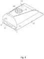
- the figures 4 and 5 show an illustration of this arrangement in connection with the third embodiment, the slider being shown in the extended position. However, said arrangement is compatible with the first and second embodiment modes.
- the slide and the sole form an assembly closed on itself, in any position of translation of the slide relative to the sole.
- the base 33 of the slider 3 comprises furrows 39 closed at two opposite ends to determine a lower translational travel than the translation travel of the rails 5, 7 or rails 6, 8 of the slider 3.
- the fixing holes 37 of the sole 1 are arranged to allow the fastening means 53 to be housed in the grooves 39 of the slider 3, when the sole 1 and the slider 3 are inserted into one another.
- the grooves 39 of the slider 3 form end stops of translation to the attachment means 53 of the sole 1 and thus determine the amplitude of the translation of the slider 3 relative to the sole 1.
- the extent of the grooves 39 of the slider 3 is determined as a function of both the perforations 19, 21 and the fixing holes 37 of the sole 1, so that the end stops of translation correspond to the retracted and extended positions of the slider 3, defined by said perforations 19, 21.
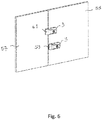
- the sole 1 To install the lock on a fixed panel 55, the only part that must be fixed therein is the sole 1. Holes are drilled in the fixed panel 55 in correspondence with the fixing holes 37 of the sole 1. The fixing means 53 of the sole 1 pass through it and are housed in the grooves 39 of the slide 3. It should be emphasized again that the lock releases an operator delicate alignment operations of the sole with a keeper to fix on the movable panel 57.
- FIG. 6 a latch according to the third embodiment is shown in a configuration where the slider 3 is in the retracted position 59 and in a configuration where the slider 3 is in the extended position 61.
- the slider 3 advantageously covers the sole 1 both in the retracted position 59 and in the extended position 61.
- the lock according to the invention can be used as a main lock or as a complementary lock with pre-existing locking means on a motor vehicle.
Landscapes
- Engineering & Computer Science (AREA)
- Mechanical Engineering (AREA)
- Footwear And Its Accessory, Manufacturing Method And Apparatuses (AREA)
- Lock And Its Accessories (AREA)
- Bearings For Parts Moving Linearly (AREA)
Abstract
Description
- L'invention se rapporte à un verrou comprenant plus particulièrement une semelle et un coulisseau, guidés en translation l'un par rapport à l'autre par des moyens de guidage, entre une position étendue et une position rétractée du coulisseau par rapport à la semelle, le coulisseau étant pourvu d'un moyen de blocage pour bloquer la translation dans l'une ou l'autre position.
- Un verrou de ce type est connu notamment du document
FR 2 997 986 - Le document
KR 20110104238 - Le document
WO 2016/019 409 divulgue un autre verrou comparable au type précédent, dans lequel la base du coulisseau est surélevée par rapport à la base de fixation de la semelle tant dans la position étendue que dans la position rétractée. La semelle est pourvue d'une perforation pour permettre l'insertion d'un doigt escamotable dans le coulisseau pour le bloquer en translation dans l'une ou l'autre position. - Le document
US 4 121 163 divulgue un autre exemple de verrou dans lequel le coulisseau est surélevé par rapport à la semelle, tant dans la position étendue que dans la position rétractée. - L'un des buts de l'invention est de modifier un verrou du type qui vient d'être rappelé, vis-à-vis du problème posé par la gâche et par son alignement avec la semelle.
- A cet effet, l'invention a pour objet un verrou conformément à celui indiqué en introduction, caractérisé en ce que le coulisseau comprend une portée qui s'étend à fleur avec la base de fixation de la semelle dans la position rétractée et dans la position étendue.
- Par cet agencement, la portée du coulisseau est maintenue dans le plan de la base de fixation de la semelle par les moyens de guidage, au cours de sa translation de la position rétractée à la position étendue. Il en résulte un verrouillage précis dans une application à une semelle unique.
- Différents modes de réalisation de l'invention sont prévus.
- Dans un premier mode de réalisation, la portée est intégrée aux moyens de guidage du coulisseau, lesquels s'étendent à fleur avec la base de fixation de la semelle. Dans un deuxième mode de réalisation, la portée est délimitée par un décrochement par rapport aux moyens de guidage du coulisseau. Dans un troisième mode de réalisation, la portée est dédoublée en une première portée intégrée aux moyens de guidage du coulisseau, lesquels s'étendent à fleur avec la base de fixation de la semelle et une deuxième portée délimitée par un décrochement par rapport auxdits moyens de guidage.
- D'autres avantages de l'invention sont exposés ci-après par la description de différents modes de réalisation illustrés par les dessins.
- La
figure 1 est une vue en éclaté illustrant un premier mode de réalisation de l'invention. - La
figure 2 est une vue en éclaté illustrant un deuxième mode de réalisation de l'invention. - La
figure 3 est une vue en éclaté illustrant un troisième mode de réalisation de l'invention. - La
figure 4 est une vue en perspective du troisième mode de réalisation de l'invention, montrant plus particulièrement le coulisseau du verrou en position étendue. - La
figure 5 est une vue en éclaté du troisième mode de réalisation de l'invention, montrant plus particulièrement la semelle et le coulisseau du verrou dans la position étendue. - La
figure 6 et une vue en perspective du troisième mode de réalisation de l'invention, montrant plus particulièrement le coulisseau installé sur un montant en position rétractée et en position étendue. - L'invention est décrite à l'aide des trois modes de réalisation mentionnés précédemment. Un élément commun à ces trois modes est désigné par la même référence.
- Un verrou selon l'un ou l'autre de ces trois modes comprend ainsi une semelle 1 et un coulisseau 3. Ces deux éléments sont guidés en translation l'un par rapport à l'autre par des moyens de guidage, les uns 5, 7, 6, 8 montés sur le coulisseau 3 et les autres 9, 11, 13, 15 montés sur la semelle 1. Ces moyens de guidage s'étendent suivant une direction Z définissant la direction de la translation du coulisseau 3, entre une position rétractée et une position étendue par rapport à la semelle 1. Le coulisseau 3 est pourvu d'un moyen de blocage 17 pour bloquer la translation dans la position rétractée ou dans la position étendue. Le blocage s'opère par la coopération du moyen de blocage 17 avec des perforations 19, 21 formées dans la semelle 1 dont l'une 19 définit la position étendue 3 et l'autre 21 définit la position rétractée. Les perforations 19, 21 sont traversantes ou borgnes. La semelle 1 comporte également des perçages de fixation 37 qui la traversent.
- Dans les trois modes de réalisation, le coulisseau 3 comprend un socle 33 et un corps 35. Les moyens de guidage 5, 7 ; 6, 8 sont intégrés au socle 33 et comprennent un premier moyen de guidage 5 ; 6 et un deuxième moyen de guidage 7 ; 8, distants l'un de l'autre pour loger le moyen de blocage 17 et loger la semelle 1 par coulissement d'un premier moyen de guidage 13 ; 9 de la semelle 1 avec le premier moyen de guidage 5 ; 6 du coulisseau 3 et coulissement d'un deuxième moyen de guidage 15 ; 11 de la semelle 1 avec le deuxième moyen de guidage 7 ; 8 du coulisseau 3.
- Selon l'invention, le coulisseau 3 comprend une portée 23, 25, 27 qui s'étend à fleur avec une base de fixation 29 de la semelle 1 dans la position rétractée et dans la position étendue. Comme cela a été précédemment souligné, la portée 23, 25, 27 du coulisseau 3 est maintenue dans le plan de la base de fixation 29 de la semelle 1 par les moyens de guidage 5, 7, 6, 8, 9, 11, 13, 15 au cours de sa translation, de la position rétractée définie par la perforation 21, à la position étendue définie par la perforation 19. Le verrou présente ainsi un verrouillage précis et fiable dans une application à semelle unique. L'expression « à fleur » signifie que la portée du coulisseau et la base de fixation de la semelle s'étendent dans un même plan.
- Le premier mode de réalisation, illustré par la
figure 1 , est particulier en ce que la portée 23, 25 est intégrée aux moyens de guidage 5, 7 lesquels s'étendent à fleur avec la base de fixation 29 de la semelle 1. Cet agencement offre une grande facilité de fabrication du coulisseau 3 par usinage d'une pièce métallique, mais présente l'inconvénient selon lequel les moyens de guidage 5, 7, dans la position étendue, y sont en partie découverts par rapport à la semelle 1. Des corps étrangers, voire un outil de vandalisme, peuvent s'y introduire et bloquer la translation. Pour cette raison, ce mode de réalisation est conseillé dans une installation intérieure du verrou. - Le deuxième mode de réalisation, illustré par la
figure 2 , est particulier en ce que la portée 27 du coulisseau 3 est délimitée par un décrochement 31 par rapport aux moyens de guidage 6, 8. Cet agencement implique un usinage un peu plus compliqué que celui décrit précédemment, mais présente l'avantage selon lequel la portée 27 referme les moyens de guidage 6, 8 du coulisseau 3 sur la semelle 1 dans la position rétractée comme dans la position étendue et empêche ainsi l'introduction d'un corps étrangers, voire d'un outil de vandalisme, entre le coulisseau 3 et la semelle 1. - Le troisième mode de réalisation, illustré par la
figure 3 , est particulier en ce que la portée du coulisseau 3 est dédoublée en une première portée 23, 25 intégrée aux moyens de guidage 5, 7 et une deuxième portée 27, délimitée par un décrochement 31 par rapport auxdits moyens de guidage 5, 7. - Dans le premier mode et le troisième mode de réalisation, les moyens de guidage 5, 7 du coulisseau sont formés d'une glissière et les moyens de guidage 13, 15 de la semelle 1 sont formés d'un rail en correspondance de forme avec la glissière et ménagé sur deux bords opposés de la semelle 1. La porté 23, 25 à fleur avec la base de fixation 29 la semelle 1 est intégrée à la glissière 5, 7. Dans le premier mode de réalisation, les glissières s'étendent d'une extrémité à une extrémité opposée du coulisseau 3 et sont accessibles pour permettre l'insertion dans les rails 13, 15 de la semelle 1 par l'une ou l'autre extrémité. Dans le troisième mode de réalisation, les glissières 5, 7 sont accessibles à une extrémité du coulisseau 3 pour permettre l'insertion dans les rails 13, 15 de la semelle 1 et sont fermées à l'extrémité opposée.
- Dans le deuxième mode de réalisation, les moyens de guidage 6, 8 du coulisseau 3 sont formés d'un rail et les moyens de guidage 9, 11 de la semelle 1 sont formés d'une glissière en correspondance de forme avec le rail. A une extrémité du coulisseau 3, la portée 27 à fleur avec la base de fixation 29 la semelle 1 est délimitée par le décrochement 31 par rapport aux rails 6, 8, du coulisseau 3. A l'extrémité opposée du coulisseau 3, les rails 6, 8 sont accessibles pour permettre l'insertion des glissières 9, 11 de la semelle 1.
- Dans les trois modes de réalisation, la portée 23, 25 ; 27 qui s'étend à fleur avec la base de fixation 29 de la semelle 1, forme une face dite inférieure du coulisseau 3, opposée au corps 35. Ce dernier est pourvu d'un alésage 41 pour recevoir un barillet comportant un cylindre 43 monté sur une plaque de fixation 45. Le cylindre 43 est pourvu d'une serrure 44 et d'un doigt rétractable 17 par rapport à la plaque de fixation 45 du cylindre 43. Ce dernier 43 est logé dans un évidement 47 formé dans le socle 33 du coulisseau où il est fixé par des moyens de fixation 49.
- Le verrou peut comprendre une cale 51 à interposer entre la base de fixation 29 de la semelle 1 et le montant sur lequel le verrou est destiné à être installé, par exemple le battant ou le coulissant d'une portière, ou encore le dormant, à l'aide de moyens de fixation 53. La cale 51 permet d'assurer une étanchéité et de décaler si nécessaire le coulisseau 3 par rapport au montant pour éviter des risques éventuels de frottement de la portée 23, 25 ; 27 lors de la translation de la position rétractée à la position étendue.
- Le coulisseau 3 et la semelle 1 sont obtenus de préférence par usinage de pièces métalliques. La cale 51 est réalisée dans un matériau non métallique, de préférence dans une matière plastique, comme par exemple un polymère thermoplastique. On préfère utiliser un matériau ayant des propriétés hydrophobes, comme par exemple le Téflon (marque enregistrée).
- Pour assembler le coulisseau 3 et la semelle 1, on actionne la serrure du cylindre 43 pour rétracter doigt rétractable 17 puis, par le socle 33, on introduit le cylindre 43 dans l'alésage 41 du coulisseau 3, jusqu'à disposer la plaque de fixation 45 dans l'évidement 47. On fixe ensuite la plaque de fixation 45 au socle 33 à l'aide des moyens de fixation 49. On insère ensuite la semelle 1 dans le coulisseau 3, pour les modes de réalisation premier ou troisième, ou le coulisseau 3 dans la semelle 1, pour le deuxième mode de réalisation. Enfin, on descend le doigt rétractable 17 par rapport au cylindre 43, dans l'une ou l'autre des perforations 19, 21 pour bloquer la translation du coulisseau 3.
- De préférence, les moyens de guidage du coulisseau 3 - glissières 5, 7 des modes de réalisation premier et troisième ou rails 6, 8 du deuxième mode de réalisation - présentent une course de translation supérieure à la course de translation des moyens de guidage de la semelle 1 - rails 13, 15 des modes de réalisation premier et troisième ou glissières 9, 11 du deuxième mode de réalisation. De plus, la perforation 19 de la semelle 1 qui détermine la position étendue du coulisseau 3 est disposée, par rapport à une extrémité desdits moyens de guidage de la semelle 1, de façon telle à ce que cette extrémité coïncide avec l'extrémité desdits moyens de guidage du coulisseau 3. Par cet agencement, le coulisseau 3 recouvre la semelle 1 tout au long de sa translation par rapport à la semelle 1.
- Les
figures 4 et5 donnent une illustration de cet agencement en rapport avec le troisième mode de réalisation, le coulisseau étant représenté dans la position étendue. Cependant, ledit agencement est compatible avec les modes mode de réalisation premier et deuxième. - Il convient cependant de noter que le troisième mode de réalisation de l'invention offre la plus grande sécurité au verrou, dans la mesure où il combine les avantages suivants :
- Les moyens de guidage du coulisseau en glissières 5, 7 dans lesquelles les moyens de guidage en rails 13, 15 de la semelle s'insèrent.
- Le dédoublement de la portée à fleur avec la base de fixation 29 de la semelle 1, en une première portée 23, 25 intégrée aux glissières 5, 7 et une deuxième portée 27 en décrochement par rapport aux glissières 5, 7.
- Une position étendue dans laquelle les glissières 5, 7 du coulisseau et les rails 13, 15 de la semelle coïncident à une extrémité.
- Par cette combinaison, le coulisseau et la semelle forment un ensemble fermé sur lui-même, dans toute position de translation du coulisseau par rapport à la semelle.
- De préférence également, le socle 33 du coulisseau 3 comprend des sillons 39 fermés à deux extrémités opposées pour déterminer une course de translation plus faible que la course de translation des glissières 5, 7 ou des rails 6, 8 du coulisseau 3. De plus, les perçages de fixation 37 de la semelle 1 y sont disposés pour permettre aux moyens de fixation 53 de se loger dans les sillons 39 du coulisseau 3, lorsque la semelle 1 et le coulisseau 3 sont insérés l'un dans l'autre. Par cet agencement, les sillons 39 du coulisseau 3 forment des butées de fin de translation aux moyens de fixation 53 de la semelle 1 et déterminent ainsi l'amplitude de la translation du coulisseau 3 par rapport à la semelle 1.
- Avantageusement, l'étendue des sillons 39 du coulisseau 3 est déterminée en fonction à la fois des perforations 19, 21 et des perçages de fixation 37 de la semelle 1, pour que les butées de fin de translation correspondent aux positions rétractée et étendue du coulisseau 3, définies par lesdites perforations 19, 21.
- Pour installer le verrou sur un panneau fixe 55, la seule pièce qui doit y être fixée est la semelle 1. Des trous sont percés dans le panneau fixe 55 en correspondance aux perçages de fixation 37 de la semelle 1. Les moyens de fixation 53 de la semelle 1 la traversent et viennent se loger dans les sillons 39 du coulisseau 3. Il convient de souligner à nouveau que le verrou libère un opérateur des opérations délicates d'alignement de la semelle avec une gâche à fixer sur le panneau mobile 57.
-
Figure 6 , un verrou selon le troisième mode de réalisation est montré dans une configuration où le coulisseau 3 est dans la position rétractée 59 et dans une configuration où le coulisseau 3 est dans la position étendue 61. Comme cela a été souligné précédemment, le coulisseau 3 recouvre avantageusement la semelle 1 tant dans la position rétractée 59 et que dans la position étendue 61. - Le verrou selon l'invention peut être utilisé comme verrou principal ou comme verrou complémentaire à moyen de verrouillage préexistant sur un véhicule automobile.
Claims (6)
- Verrou comprenant une semelle (1) et un coulisseau (3), guidés en translation l'un par rapport à l'autre par des moyens de guidage (5,7,6,8,9,11,13,15) entre une position étendue (61) et une position rétractée (59) du coulisseau par rapport à la semelle, le coulisseau étant pourvu d'un moyen de blocage (17) pour bloquer la translation dans l'une ou l'autre position, caractérisé en ce que le coulisseau comprend une portée (23,25,27) qui s'étend à fleur avec une base de fixation (29) de la semelle dans la position rétractée et dans la position étendue.
- Verrou selon la revendication 1, caractérisé en ce que la portée (23,25) est intégrée aux moyens de guidage (5,7) du coulisseau, lesquels s'étendent à fleur avec la base de fixation (29) de la semelle.
- Verrou selon la revendication 1, caractérisé en ce que la portée (27) est délimitée par un décrochement (31) par rapport aux moyens de guidage (6,8) du coulisseau.
- Verrou selon la revendication 1, caractérisé en ce que la portée est dédoublée en une première portée (23,25) intégrée aux moyens de guidage (5,7) du coulisseau, lesquels s'étendent à fleur avec la base de fixation (29) de la semelle et une deuxième portée (27) délimitée par un décrochement (31) par rapport auxdits moyens de guidage (5,7).
- Verrou selon la revendication 1, caractérisé en ce que les moyens de guidage (5,7,6,8) du coulisseau présentent une course de translation supérieure à une course de translation des moyens de guidage (9,11,13,15) de la semelle et en ce que la semelle comprend une perforation (19) qui détermine la position étendue (61) du coulisseau par coopération avec le moyen de blocage (17) et qui est disposée de façon telle que les moyens de guidage du coulisseau et de la semelle sont en coïncidence dans la position étendue.
- Verrou selon la revendication 1, caractérisé en ce que le coulisseau comprend des sillons (39) fermés à deux extrémités opposées pour déterminer une course de translation plus faible qu'une course de translation des moyens de guidage (5,7,6,8) du coulisseau et dans lesquels des moyens de fixation (53) sont reçus en traversant la semelle par des perçages de fixation (37).
Applications Claiming Priority (1)
| Application Number | Priority Date | Filing Date | Title |
|---|---|---|---|
| FR1800438A FR3080638B1 (fr) | 2018-04-25 | 2018-04-25 | Dispositif de verrouillage pour portes |
Publications (2)
| Publication Number | Publication Date |
|---|---|
| EP3561205A1 true EP3561205A1 (fr) | 2019-10-30 |
| EP3561205B1 EP3561205B1 (fr) | 2020-11-18 |
Family
ID=62873398
Family Applications (1)
| Application Number | Title | Priority Date | Filing Date |
|---|---|---|---|
| EP19170789.2A Active EP3561205B1 (fr) | 2018-04-25 | 2019-04-24 | Verrou comprenant une portee de coulisseau a fleur avec une base de fixation de semelle |
Country Status (3)
| Country | Link |
|---|---|
| EP (1) | EP3561205B1 (fr) |
| ES (1) | ES2837630T3 (fr) |
| FR (1) | FR3080638B1 (fr) |
Cited By (1)
| Publication number | Priority date | Publication date | Assignee | Title |
|---|---|---|---|---|
| WO2021259859A1 (fr) | 2020-06-26 | 2021-12-30 | Imc Creations | Verrou comprenant un coulisseau à fleur par rapport à une semelle pourvue d'un évidement pour recevoir une butée de translation du coulisseau |
Citations (4)
| Publication number | Priority date | Publication date | Assignee | Title |
|---|---|---|---|---|
| US4095828A (en) * | 1977-02-14 | 1978-06-20 | Eldon Dwayne East | Locking assembly |
| WO2011143687A1 (fr) * | 2010-05-21 | 2011-11-24 | Steel Storage Holdings Pty Ltd | Ensemble serrure de porte |
| FR2997986A1 (fr) * | 2012-11-12 | 2014-05-16 | Inducteurs Montage Creation | Dispositif de verrouillage a cle pour portes de vehicules |
| WO2016019409A1 (fr) * | 2014-08-04 | 2016-02-11 | Steel Storage Holdings Pty Ltd | Agencement de serrure |
Family Cites Families (3)
| Publication number | Priority date | Publication date | Assignee | Title |
|---|---|---|---|---|
| US1490988A (en) * | 1923-02-17 | 1924-04-22 | Harry E Soref | Combined padlock and doorbolt |
| US4121863A (en) * | 1977-11-14 | 1978-10-24 | Caterpillar Tractor Co. | Latch assembly |
| KR101102589B1 (ko) * | 2010-03-16 | 2012-01-03 | 오세민 | 도어 잠금장치 및 화장실 도어 잠금장치 |
-
2018
- 2018-04-25 FR FR1800438A patent/FR3080638B1/fr active Active
-
2019
- 2019-04-24 EP EP19170789.2A patent/EP3561205B1/fr active Active
- 2019-04-24 ES ES19170789T patent/ES2837630T3/es active Active
Patent Citations (4)
| Publication number | Priority date | Publication date | Assignee | Title |
|---|---|---|---|---|
| US4095828A (en) * | 1977-02-14 | 1978-06-20 | Eldon Dwayne East | Locking assembly |
| WO2011143687A1 (fr) * | 2010-05-21 | 2011-11-24 | Steel Storage Holdings Pty Ltd | Ensemble serrure de porte |
| FR2997986A1 (fr) * | 2012-11-12 | 2014-05-16 | Inducteurs Montage Creation | Dispositif de verrouillage a cle pour portes de vehicules |
| WO2016019409A1 (fr) * | 2014-08-04 | 2016-02-11 | Steel Storage Holdings Pty Ltd | Agencement de serrure |
Cited By (3)
| Publication number | Priority date | Publication date | Assignee | Title |
|---|---|---|---|---|
| WO2021259859A1 (fr) | 2020-06-26 | 2021-12-30 | Imc Creations | Verrou comprenant un coulisseau à fleur par rapport à une semelle pourvue d'un évidement pour recevoir une butée de translation du coulisseau |
| FR3111931A1 (fr) | 2020-06-26 | 2021-12-31 | IMC Créations | Verrou dont le coulisseau est à fleur par rapport à la semelle et est pourvu d’un moyen de blocage rétractable ou escamotable formant butée |
| US12392173B2 (en) | 2020-06-26 | 2025-08-19 | Imc Creations | Lock comprising a slider flush relative to a sole plate provided with a recess for receiving a translation stop preventing the slider from translating |
Also Published As
| Publication number | Publication date |
|---|---|
| EP3561205B1 (fr) | 2020-11-18 |
| ES2837630T3 (es) | 2021-07-01 |
| FR3080638B1 (fr) | 2022-05-13 |
| FR3080638A1 (fr) | 2019-11-01 |
Similar Documents
| Publication | Publication Date | Title |
|---|---|---|
| EP0869241B1 (fr) | Ferrure de verrouillage pour ouvrant coulissant | |
| US20220290466A1 (en) | Sliding window assembly | |
| EP3561205B1 (fr) | Verrou comprenant une portee de coulisseau a fleur avec une base de fixation de semelle | |
| WO2000001910A1 (fr) | Leve-vitre de porte de vehicule a fixation automatique a la vitre du curseur support de vitre | |
| EP2650460A2 (fr) | Dispositif de fermeture provisoire d'un élément ouvrant sur un élément support | |
| EP1182311B1 (fr) | Plaquette de réglage d'une gâche de serrure de véhicule automobile | |
| CA3180421C (fr) | Verrou comprenant un coulisseau a fleur par rapport a une semelle pourvue d'un evidement pour recevoir une butee de translation du coulisseau | |
| FR2892058A1 (fr) | Perfectionnements aux mecanismes d'ouverture et de fermeture de panneaux mobiles pour les fenetres de vehicule | |
| EP0882861B1 (fr) | Ferrure de verrouillage pour ouvrant coulissant | |
| FR2897230A1 (fr) | Dispositif d'obturation perfectionne a volet mobile | |
| FR2516147A1 (fr) | Penture reglable | |
| EP0997598B1 (fr) | Dispositif de type guide-vis pour cremone ou cremone-serrure | |
| FR2497545A1 (fr) | Dispositif pour la fixation d'un element d'installation sur une porte ou un panneau en glace | |
| EP4534781A1 (fr) | Dispositif de commande de ferrure de verrouillage pour menuiserie de type porte ou fenêtre | |
| EP1605119B1 (fr) | Dispositif de verrouillage pour porte, fenêtre ou porte-fenêtre coulissante | |
| FR2859137A1 (fr) | Agencement d'un element de rigidification de deux portes a ouverture antagoniste | |
| EP0241397B1 (fr) | Crémone à têtière à double direction | |
| FR2857686A1 (fr) | Ferrure de verrouillage pour ouvrant coulissant | |
| FR2718177A1 (fr) | Dispositif de verrouillage d'une grille sur un châssis ou analogue. | |
| FR2503810A1 (fr) | Patin de guidage de panneau coulissant, en particulier pour toit ouvrant de vehicule | |
| FR2572454A1 (fr) | Porte a deux vantaux. | |
| EP3306015A1 (fr) | Dispositif de commande d'une ferrure de verrouillage/déverrouillage d'un ouvrant | |
| FR2641817A1 (fr) | Profile formant gache de serrure | |
| FR2573807A1 (fr) | Dispositif perfectionne de blocage et fermeture d'un ouvrant comportant une gache a deux logements | |
| FR2809448A1 (fr) | Menuiserie comportant une gache de fermeture et des cales de transport |
Legal Events
| Date | Code | Title | Description |
|---|---|---|---|
| PUAI | Public reference made under article 153(3) epc to a published international application that has entered the european phase |
Free format text: ORIGINAL CODE: 0009012 |
|
| STAA | Information on the status of an ep patent application or granted ep patent |
Free format text: STATUS: THE APPLICATION HAS BEEN PUBLISHED |
|
| AK | Designated contracting states |
Kind code of ref document: A1 Designated state(s): AL AT BE BG CH CY CZ DE DK EE ES FI FR GB GR HR HU IE IS IT LI LT LU LV MC MK MT NL NO PL PT RO RS SE SI SK SM TR |
|
| AX | Request for extension of the european patent |
Extension state: BA ME |
|
| STAA | Information on the status of an ep patent application or granted ep patent |
Free format text: STATUS: REQUEST FOR EXAMINATION WAS MADE |
|
| 17P | Request for examination filed |
Effective date: 20191215 |
|
| RBV | Designated contracting states (corrected) |
Designated state(s): AL AT BE BG CH CY CZ DE DK EE ES FI FR GB GR HR HU IE IS IT LI LT LU LV MC MK MT NL NO PL PT RO RS SE SI SK SM TR |
|
| GRAP | Despatch of communication of intention to grant a patent |
Free format text: ORIGINAL CODE: EPIDOSNIGR1 |
|
| STAA | Information on the status of an ep patent application or granted ep patent |
Free format text: STATUS: GRANT OF PATENT IS INTENDED |
|
| RIC1 | Information provided on ipc code assigned before grant |
Ipc: E05C 1/04 20060101ALI20200225BHEP Ipc: E05B 17/20 20060101ALI20200225BHEP Ipc: E05B 17/04 20060101ALI20200225BHEP Ipc: E05B 85/06 20140101AFI20200225BHEP Ipc: E05C 1/00 20060101ALI20200225BHEP |
|
| INTG | Intention to grant announced |
Effective date: 20200311 |
|
| GRAS | Grant fee paid |
Free format text: ORIGINAL CODE: EPIDOSNIGR3 |
|
| GRAJ | Information related to disapproval of communication of intention to grant by the applicant or resumption of examination proceedings by the epo deleted |
Free format text: ORIGINAL CODE: EPIDOSDIGR1 |
|
| GRAL | Information related to payment of fee for publishing/printing deleted |
Free format text: ORIGINAL CODE: EPIDOSDIGR3 |
|
| STAA | Information on the status of an ep patent application or granted ep patent |
Free format text: STATUS: REQUEST FOR EXAMINATION WAS MADE |
|
| GRAP | Despatch of communication of intention to grant a patent |
Free format text: ORIGINAL CODE: EPIDOSNIGR1 |
|
| STAA | Information on the status of an ep patent application or granted ep patent |
Free format text: STATUS: GRANT OF PATENT IS INTENDED |
|
| GRAJ | Information related to disapproval of communication of intention to grant by the applicant or resumption of examination proceedings by the epo deleted |
Free format text: ORIGINAL CODE: EPIDOSDIGR1 |
|
| STAA | Information on the status of an ep patent application or granted ep patent |
Free format text: STATUS: REQUEST FOR EXAMINATION WAS MADE |
|
| INTC | Intention to grant announced (deleted) | ||
| INTG | Intention to grant announced |
Effective date: 20200827 |
|
| GRAP | Despatch of communication of intention to grant a patent |
Free format text: ORIGINAL CODE: EPIDOSNIGR1 |
|
| STAA | Information on the status of an ep patent application or granted ep patent |
Free format text: STATUS: GRANT OF PATENT IS INTENDED |
|
| INTC | Intention to grant announced (deleted) | ||
| GRAA | (expected) grant |
Free format text: ORIGINAL CODE: 0009210 |
|
| STAA | Information on the status of an ep patent application or granted ep patent |
Free format text: STATUS: THE PATENT HAS BEEN GRANTED |
|
| INTG | Intention to grant announced |
Effective date: 20201007 |
|
| AK | Designated contracting states |
Kind code of ref document: B1 Designated state(s): AL AT BE BG CH CY CZ DE DK EE ES FI FR GB GR HR HU IE IS IT LI LT LU LV MC MK MT NL NO PL PT RO RS SE SI SK SM TR |
|
| REG | Reference to a national code |
Ref country code: GB Ref legal event code: FG4D Free format text: NOT ENGLISH |
|
| REG | Reference to a national code |
Ref country code: CH Ref legal event code: EP |
|
| REG | Reference to a national code |
Ref country code: IE Ref legal event code: FG4D Free format text: LANGUAGE OF EP DOCUMENT: FRENCH |
|
| REG | Reference to a national code |
Ref country code: DE Ref legal event code: R096 Ref document number: 602019001345 Country of ref document: DE |
|
| REG | Reference to a national code |
Ref country code: AT Ref legal event code: REF Ref document number: 1335961 Country of ref document: AT Kind code of ref document: T Effective date: 20201215 |
|
| REG | Reference to a national code |
Ref country code: AT Ref legal event code: MK05 Ref document number: 1335961 Country of ref document: AT Kind code of ref document: T Effective date: 20201118 |
|
| REG | Reference to a national code |
Ref country code: NL Ref legal event code: MP Effective date: 20201118 |
|
| PG25 | Lapsed in a contracting state [announced via postgrant information from national office to epo] |
Ref country code: GR Free format text: LAPSE BECAUSE OF FAILURE TO SUBMIT A TRANSLATION OF THE DESCRIPTION OR TO PAY THE FEE WITHIN THE PRESCRIBED TIME-LIMIT Effective date: 20210219 Ref country code: NO Free format text: LAPSE BECAUSE OF FAILURE TO SUBMIT A TRANSLATION OF THE DESCRIPTION OR TO PAY THE FEE WITHIN THE PRESCRIBED TIME-LIMIT Effective date: 20210218 Ref country code: PT Free format text: LAPSE BECAUSE OF FAILURE TO SUBMIT A TRANSLATION OF THE DESCRIPTION OR TO PAY THE FEE WITHIN THE PRESCRIBED TIME-LIMIT Effective date: 20210318 Ref country code: RS Free format text: LAPSE BECAUSE OF FAILURE TO SUBMIT A TRANSLATION OF THE DESCRIPTION OR TO PAY THE FEE WITHIN THE PRESCRIBED TIME-LIMIT Effective date: 20201118 Ref country code: FI Free format text: LAPSE BECAUSE OF FAILURE TO SUBMIT A TRANSLATION OF THE DESCRIPTION OR TO PAY THE FEE WITHIN THE PRESCRIBED TIME-LIMIT Effective date: 20201118 |
|
| PG25 | Lapsed in a contracting state [announced via postgrant information from national office to epo] |
Ref country code: PL Free format text: LAPSE BECAUSE OF FAILURE TO SUBMIT A TRANSLATION OF THE DESCRIPTION OR TO PAY THE FEE WITHIN THE PRESCRIBED TIME-LIMIT Effective date: 20201118 Ref country code: LV Free format text: LAPSE BECAUSE OF FAILURE TO SUBMIT A TRANSLATION OF THE DESCRIPTION OR TO PAY THE FEE WITHIN THE PRESCRIBED TIME-LIMIT Effective date: 20201118 Ref country code: IS Free format text: LAPSE BECAUSE OF FAILURE TO SUBMIT A TRANSLATION OF THE DESCRIPTION OR TO PAY THE FEE WITHIN THE PRESCRIBED TIME-LIMIT Effective date: 20210318 Ref country code: SE Free format text: LAPSE BECAUSE OF FAILURE TO SUBMIT A TRANSLATION OF THE DESCRIPTION OR TO PAY THE FEE WITHIN THE PRESCRIBED TIME-LIMIT Effective date: 20201118 Ref country code: BG Free format text: LAPSE BECAUSE OF FAILURE TO SUBMIT A TRANSLATION OF THE DESCRIPTION OR TO PAY THE FEE WITHIN THE PRESCRIBED TIME-LIMIT Effective date: 20210218 Ref country code: AT Free format text: LAPSE BECAUSE OF FAILURE TO SUBMIT A TRANSLATION OF THE DESCRIPTION OR TO PAY THE FEE WITHIN THE PRESCRIBED TIME-LIMIT Effective date: 20201118 |
|
| REG | Reference to a national code |
Ref country code: LT Ref legal event code: MG9D |
|
| PG25 | Lapsed in a contracting state [announced via postgrant information from national office to epo] |
Ref country code: HR Free format text: LAPSE BECAUSE OF FAILURE TO SUBMIT A TRANSLATION OF THE DESCRIPTION OR TO PAY THE FEE WITHIN THE PRESCRIBED TIME-LIMIT Effective date: 20201118 |
|
| PG25 | Lapsed in a contracting state [announced via postgrant information from national office to epo] |
Ref country code: LT Free format text: LAPSE BECAUSE OF FAILURE TO SUBMIT A TRANSLATION OF THE DESCRIPTION OR TO PAY THE FEE WITHIN THE PRESCRIBED TIME-LIMIT Effective date: 20201118 Ref country code: RO Free format text: LAPSE BECAUSE OF FAILURE TO SUBMIT A TRANSLATION OF THE DESCRIPTION OR TO PAY THE FEE WITHIN THE PRESCRIBED TIME-LIMIT Effective date: 20201118 Ref country code: EE Free format text: LAPSE BECAUSE OF FAILURE TO SUBMIT A TRANSLATION OF THE DESCRIPTION OR TO PAY THE FEE WITHIN THE PRESCRIBED TIME-LIMIT Effective date: 20201118 Ref country code: SM Free format text: LAPSE BECAUSE OF FAILURE TO SUBMIT A TRANSLATION OF THE DESCRIPTION OR TO PAY THE FEE WITHIN THE PRESCRIBED TIME-LIMIT Effective date: 20201118 Ref country code: SK Free format text: LAPSE BECAUSE OF FAILURE TO SUBMIT A TRANSLATION OF THE DESCRIPTION OR TO PAY THE FEE WITHIN THE PRESCRIBED TIME-LIMIT Effective date: 20201118 Ref country code: CZ Free format text: LAPSE BECAUSE OF FAILURE TO SUBMIT A TRANSLATION OF THE DESCRIPTION OR TO PAY THE FEE WITHIN THE PRESCRIBED TIME-LIMIT Effective date: 20201118 |
|
| REG | Reference to a national code |
Ref country code: DE Ref legal event code: R097 Ref document number: 602019001345 Country of ref document: DE |
|
| PG25 | Lapsed in a contracting state [announced via postgrant information from national office to epo] |
Ref country code: DK Free format text: LAPSE BECAUSE OF FAILURE TO SUBMIT A TRANSLATION OF THE DESCRIPTION OR TO PAY THE FEE WITHIN THE PRESCRIBED TIME-LIMIT Effective date: 20201118 |
|
| PLBE | No opposition filed within time limit |
Free format text: ORIGINAL CODE: 0009261 |
|
| STAA | Information on the status of an ep patent application or granted ep patent |
Free format text: STATUS: NO OPPOSITION FILED WITHIN TIME LIMIT |
|
| 26N | No opposition filed |
Effective date: 20210819 |
|
| PG25 | Lapsed in a contracting state [announced via postgrant information from national office to epo] |
Ref country code: NL Free format text: LAPSE BECAUSE OF FAILURE TO SUBMIT A TRANSLATION OF THE DESCRIPTION OR TO PAY THE FEE WITHIN THE PRESCRIBED TIME-LIMIT Effective date: 20201118 Ref country code: AL Free format text: LAPSE BECAUSE OF FAILURE TO SUBMIT A TRANSLATION OF THE DESCRIPTION OR TO PAY THE FEE WITHIN THE PRESCRIBED TIME-LIMIT Effective date: 20201118 |
|
| PG25 | Lapsed in a contracting state [announced via postgrant information from national office to epo] |
Ref country code: SI Free format text: LAPSE BECAUSE OF FAILURE TO SUBMIT A TRANSLATION OF THE DESCRIPTION OR TO PAY THE FEE WITHIN THE PRESCRIBED TIME-LIMIT Effective date: 20201118 Ref country code: MC Free format text: LAPSE BECAUSE OF FAILURE TO SUBMIT A TRANSLATION OF THE DESCRIPTION OR TO PAY THE FEE WITHIN THE PRESCRIBED TIME-LIMIT Effective date: 20201118 |
|
| PG25 | Lapsed in a contracting state [announced via postgrant information from national office to epo] |
Ref country code: LU Free format text: LAPSE BECAUSE OF NON-PAYMENT OF DUE FEES Effective date: 20210424 |
|
| PG25 | Lapsed in a contracting state [announced via postgrant information from national office to epo] |
Ref country code: IE Free format text: LAPSE BECAUSE OF NON-PAYMENT OF DUE FEES Effective date: 20210424 |
|
| PG25 | Lapsed in a contracting state [announced via postgrant information from national office to epo] |
Ref country code: IS Free format text: LAPSE BECAUSE OF FAILURE TO SUBMIT A TRANSLATION OF THE DESCRIPTION OR TO PAY THE FEE WITHIN THE PRESCRIBED TIME-LIMIT Effective date: 20210318 |
|
| P01 | Opt-out of the competence of the unified patent court (upc) registered |
Effective date: 20230514 |
|
| P02 | Opt-out of the competence of the unified patent court (upc) changed |
Effective date: 20230514 |
|
| PG25 | Lapsed in a contracting state [announced via postgrant information from national office to epo] |
Ref country code: CY Free format text: LAPSE BECAUSE OF FAILURE TO SUBMIT A TRANSLATION OF THE DESCRIPTION OR TO PAY THE FEE WITHIN THE PRESCRIBED TIME-LIMIT Effective date: 20201118 |
|
| PG25 | Lapsed in a contracting state [announced via postgrant information from national office to epo] |
Ref country code: HU Free format text: LAPSE BECAUSE OF FAILURE TO SUBMIT A TRANSLATION OF THE DESCRIPTION OR TO PAY THE FEE WITHIN THE PRESCRIBED TIME-LIMIT; INVALID AB INITIO Effective date: 20190424 |
|
| PG25 | Lapsed in a contracting state [announced via postgrant information from national office to epo] |
Ref country code: MK Free format text: LAPSE BECAUSE OF FAILURE TO SUBMIT A TRANSLATION OF THE DESCRIPTION OR TO PAY THE FEE WITHIN THE PRESCRIBED TIME-LIMIT Effective date: 20201118 |
|
| PG25 | Lapsed in a contracting state [announced via postgrant information from national office to epo] |
Ref country code: MT Free format text: LAPSE BECAUSE OF FAILURE TO SUBMIT A TRANSLATION OF THE DESCRIPTION OR TO PAY THE FEE WITHIN THE PRESCRIBED TIME-LIMIT Effective date: 20201118 |
|
| PGFP | Annual fee paid to national office [announced via postgrant information from national office to epo] |
Ref country code: DE Payment date: 20250318 Year of fee payment: 7 |
|
| PGFP | Annual fee paid to national office [announced via postgrant information from national office to epo] |
Ref country code: ES Payment date: 20250505 Year of fee payment: 7 |
|
| PGFP | Annual fee paid to national office [announced via postgrant information from national office to epo] |
Ref country code: IT Payment date: 20250319 Year of fee payment: 7 |
|
| PGFP | Annual fee paid to national office [announced via postgrant information from national office to epo] |
Ref country code: CH Payment date: 20250501 Year of fee payment: 7 |
|
| PG25 | Lapsed in a contracting state [announced via postgrant information from national office to epo] |
Ref country code: TR Free format text: LAPSE BECAUSE OF FAILURE TO SUBMIT A TRANSLATION OF THE DESCRIPTION OR TO PAY THE FEE WITHIN THE PRESCRIBED TIME-LIMIT Effective date: 20201118 |
|
| PGFP | Annual fee paid to national office [announced via postgrant information from national office to epo] |
Ref country code: GB Payment date: 20260317 Year of fee payment: 8 |
|
| PGFP | Annual fee paid to national office [announced via postgrant information from national office to epo] |
Ref country code: BE Payment date: 20260318 Year of fee payment: 8 |
|
| PGFP | Annual fee paid to national office [announced via postgrant information from national office to epo] |
Ref country code: FR Payment date: 20260313 Year of fee payment: 8 |