EP3560860A1 - Conveyor belt for bulk powdered or granular material - Google Patents
Conveyor belt for bulk powdered or granular material Download PDFInfo
- Publication number
- EP3560860A1 EP3560860A1 EP19171220.7A EP19171220A EP3560860A1 EP 3560860 A1 EP3560860 A1 EP 3560860A1 EP 19171220 A EP19171220 A EP 19171220A EP 3560860 A1 EP3560860 A1 EP 3560860A1
- Authority
- EP
- European Patent Office
- Prior art keywords
- conveyor belt
- conveyor
- pulverulent
- granular material
- belt
- Prior art date
- Legal status (The legal status is an assumption and is not a legal conclusion. Google has not performed a legal analysis and makes no representation as to the accuracy of the status listed.)
- Withdrawn
Links
Images

Classifications
-
- B—PERFORMING OPERATIONS; TRANSPORTING
- B65—CONVEYING; PACKING; STORING; HANDLING THIN OR FILAMENTARY MATERIAL
- B65G—TRANSPORT OR STORAGE DEVICES, e.g. CONVEYORS FOR LOADING OR TIPPING, SHOP CONVEYOR SYSTEMS OR PNEUMATIC TUBE CONVEYORS
- B65G21/00—Supporting or protective framework or housings for endless load-carriers or traction elements of belt or chain conveyors
- B65G21/20—Means incorporated in, or attached to, framework or housings for guiding load-carriers, traction elements or loads supported on moving surfaces
- B65G21/2045—Mechanical means for guiding or retaining the load on the load-carrying surface
- B65G21/2063—Mechanical means for guiding or retaining the load on the load-carrying surface comprising elements not movable in the direction of load-transport
- B65G21/209—Mechanical means for guiding or retaining the load on the load-carrying surface comprising elements not movable in the direction of load-transport for augmenting or creating a pression force between the load and the load-carrying surface
-
- B—PERFORMING OPERATIONS; TRANSPORTING
- B65—CONVEYING; PACKING; STORING; HANDLING THIN OR FILAMENTARY MATERIAL
- B65G—TRANSPORT OR STORAGE DEVICES, e.g. CONVEYORS FOR LOADING OR TIPPING, SHOP CONVEYOR SYSTEMS OR PNEUMATIC TUBE CONVEYORS
- B65G15/00—Conveyors having endless load-conveying surfaces, i.e. belts and like continuous members, to which tractive effort is transmitted by means other than endless driving elements of similar configuration
- B65G15/10—Conveyors having endless load-conveying surfaces, i.e. belts and like continuous members, to which tractive effort is transmitted by means other than endless driving elements of similar configuration comprising two or more co-operating endless surfaces with parallel longitudinal axes, or a multiplicity of parallel elements, e.g. ropes defining an endless surface
- B65G15/12—Conveyors having endless load-conveying surfaces, i.e. belts and like continuous members, to which tractive effort is transmitted by means other than endless driving elements of similar configuration comprising two or more co-operating endless surfaces with parallel longitudinal axes, or a multiplicity of parallel elements, e.g. ropes defining an endless surface with two or more endless belts
- B65G15/18—Conveyors having endless load-conveying surfaces, i.e. belts and like continuous members, to which tractive effort is transmitted by means other than endless driving elements of similar configuration comprising two or more co-operating endless surfaces with parallel longitudinal axes, or a multiplicity of parallel elements, e.g. ropes defining an endless surface with two or more endless belts the belts being sealed at their edges
-
- B—PERFORMING OPERATIONS; TRANSPORTING
- B65—CONVEYING; PACKING; STORING; HANDLING THIN OR FILAMENTARY MATERIAL
- B65G—TRANSPORT OR STORAGE DEVICES, e.g. CONVEYORS FOR LOADING OR TIPPING, SHOP CONVEYOR SYSTEMS OR PNEUMATIC TUBE CONVEYORS
- B65G15/00—Conveyors having endless load-conveying surfaces, i.e. belts and like continuous members, to which tractive effort is transmitted by means other than endless driving elements of similar configuration
- B65G15/30—Belts or like endless load-carriers
- B65G15/32—Belts or like endless load-carriers made of rubber or plastics
- B65G15/42—Belts or like endless load-carriers made of rubber or plastics having ribs, ridges, or other surface projections
- B65G15/44—Belts or like endless load-carriers made of rubber or plastics having ribs, ridges, or other surface projections for impelling the loads
-
- B—PERFORMING OPERATIONS; TRANSPORTING
- B65—CONVEYING; PACKING; STORING; HANDLING THIN OR FILAMENTARY MATERIAL
- B65G—TRANSPORT OR STORAGE DEVICES, e.g. CONVEYORS FOR LOADING OR TIPPING, SHOP CONVEYOR SYSTEMS OR PNEUMATIC TUBE CONVEYORS
- B65G2201/00—Indexing codes relating to handling devices, e.g. conveyors, characterised by the type of product or load being conveyed or handled
- B65G2201/04—Bulk
Definitions
- Certain existing belt conveyors also allow inclined, for example substantially vertical, transport of the pulverulent or granular material by trapping the pulverulent or granular material between two endless conveyor belts, one of which comprises buckets on its outer surface, the surface internal of each of said two conveyor belts sliding on a plurality of rollers or sliding plates.
- These existing belt conveyors thus make it possible to load a truck by raising the pulverulent or granular material above the truck body, or to fill a silo by raising the pulverulent or granular material towards the top of the silo.
- the British patent application GB395031A discloses such a conveyor belt substantially vertical.
- the conveyor belt according to the invention allows an elevation of the pulverulent or granular material transported between the two conveyor belts, the elevation height depending on the inclination and the length of the two conveyor belts.
- the two conveyor belts have opposite directions of rotation and are ascending in the elevation region of pulverulent or granular material.
- the cleats of the first conveyor belt are contiguous with the outer surface of the second conveyor belt in the elevation region of pulverulent or granular material, compartments are formed between two successive cleats of the first conveyor belt in the region of elevation of pulverulent or granular material, each compartment being adapted to receive pulverulent or granular material to allow its elevation.
- the conveyor thus makes it possible to transport the pulverulent or granular material at an angle of up to 90 ° without damaging it, by imprisoning the pulverulent or granular material in the compartments formed between the two conveyor belts in the region of elevation of pulverulent or granular material, the second conveyor belt driving the pulverulent or granular material and the first conveyor belt capturing and trapping the pulverulent or granular material between its cleats.
- the cleats preferably have a long and relatively thin shape with a square or rectangular section, but could also take any shape, such as a chevron shape, without departing from the scope of the present invention.
- the cleats of the second conveyor belt are preferably arranged in staggered relation to those of the first conveyor belt.
- the two guide rollers make it possible to create a bend on the second conveyor belt in order to create an upper part, preferably a substantially horizontal one, of the second conveyor belt, the said substantially horizontal upper part of the second conveyor belt making it possible to transport the material pulverulent or granular to a collector or the top of a heap of pulverulent or granular material, once the pulverulent or granular material has been raised by the joint action of the two conveyor belts.
- the inclination of the ascending parts of the first and second conveyor belts in the elevation region of pulverulent or granular material is identical and between 85 ° and 90 ° relative to the horizontal.
- the belt conveyor further comprises a sweeper device arranged upstream of the first and second conveyor belts.
- the sweeper device arranged in the lower part of the belt conveyor, drives the pulverulent material or granular to the conveyor belts at their lower drums.
- the belt conveyor further comprises a frame on which the first and second lower drums, the first and second upper drums, the first and second sliding floors and, where appropriate, the sweeper and the at least two guide rollers are attached.
- the lower drum of the second conveyor belt being slightly lower than the lower drum of the first conveyor belt, the pulverulent or granular material can be collected very low, practically at ground level.
- v1 is the speed of the second conveyor belt and v2 is the speed of the first conveyor belt, then v1> v2, so that it can not accumulate material, that is to say dust, between the heads of the cleats and the second conveyor belt, which could cause jams.
- the first and second conveyor belts are made of at least one plastic material among the strips marketed in standard manner; natural or synthetic rubber, soft plastics, polyethylene, polyvinyl chloride (PVC), silicone.
- the first and second flat sliding floors are made of at least one material among metals (for example, iron, aluminum and / or copper) and their alloys, plastics (for example, high density polyethylene (HDPE) and / or polyvinyl chloride (PVC)) and composite materials.
- metals for example, iron, aluminum and / or copper
- plastics for example, high density polyethylene (HDPE) and / or polyvinyl chloride (PVC)
- HDPE high density polyethylene
- PVC polyvinyl chloride
- the first conveyor belt 2 is adapted to be rotated by a first lower rotary drum 4a and a first upper rotary drum 4b.
- the second conveyor belt 3 is adapted to be rotated by a second lower rotary drum 5a and a second upper rotary drum 5b.
- the belt conveyor 1 further comprises a frame 6 on which the first and second lower drums 4a, 5a and the first and second upper drums 4b, 5b are set in rotation, said first and second lower drums 4a, 5a and said first and second second upper drums 4b, 5b being rotated by one or more motors, which may in particular be electric, pneumatic or hydraulic motors (not shown in FIGS. Figures 1 and 2 ) and / or one or more gears (not shown in Figures 1 and 2 ).
- motors which may in particular be electric, pneumatic or hydraulic motors (not shown in FIGS. Figures 1 and 2 ) and / or one or more gears (not shown in Figures 1 and 2 ).
- the lower wall 6b of the frame 6 is disposed under the first and second lower drums 4a, 5a.
- the second conveyor belt 3 could also comprise cleats distributed on its outer surface, without departing from the scope of the present invention.
- the cleats 7 have a rectilinear shape and relatively thin square or rectangular section, but could also take any shape, such as a chevron shape, without departing from the scope of the present invention.
- the first and second conveyor belts 2, 3 are made from at least one of the commercially available strips; rubber natural or synthetic, flexible plastics, polyethylene, polyvinyl chloride (PVC), silicone.
- the cleats 7 are made of the same material as the first conveyor belt 2.
- the first conveyor belt 2 and the lower portion 3a of the second conveyor belt 3 are inclined relative to the horizontal.
- the inclination of the first conveyor belt 2 and the lower portion 3a of the second conveyor belt 3 is identical and substantially 90 ° with respect to the horizontal.
- the belt conveyor 3 further comprises first and second flat sliding floors 8, 9 on which the first and second conveyor belts 2, 3 are respectively configured to slide, said first and second flat sliding floors 8, 9 being arranged respectively against the internal surfaces of the ascending parts of the first and second bands conveyors 2, 3 in the region of elevation of pulverulent or granular material.
- the belt conveyor 1 further comprises a lower guide roller 10a and an upper guide roller 10b configured to bend the second conveyor belt 3 past the elevation region of pulverulent or granular material.
- the upper guide roller 10b has a height slightly less than that of the first upper drum 4b of the first conveyor belt 2, the guide roller 10a having a height smaller than that of the upper guide roller 10b.
- the lower guide rollers 10a and 10b are attached to the frame 6.
- the two guide rollers 10a, 10b thus make it possible to create a bend on the second conveyor belt 3 to create an upper portion 3b of the second conveyor belt 3 which has a small inclination with respect to the horizontal.
- the upper part 3b of the second conveyor belt 3 could also be horizontal or downward, without departing from the scope of the present invention.
- the upper part 3b of the second conveyor belt 3 makes it possible to transport the pulverulent or granular material to a collector or the top of a pile of pulverulent or granular material, once the pulverulent or granular material has been raised by the joint action.
- the arrows shown on the first and second lower drums 4a, 5a at the Figure 3 indicate the direction of rotation of the latter.
- the compartments 12 formed between the two conveyor belts 2, 3 are also regular, the quantity of pulverulent or granular material transported in each compartment 12 being thus identical.
- the pulverulent or granular material 11 can thus first be discharged on the lower wall 6b of the frame 6 at the first and second lower drums 4a, 5a of the belt conveyor 1, and then be raised by the joint action of the two bands. 2, 3, before being unloaded by the upper part 3b of the second conveyor belt 3 to a collector such as a silo or a truck body.
- a collector such as a silo or a truck body.
- the speed of rotation of the second conveyor belt 3 is greater than that of the first conveyor belt 2, so that it can not accumulate material, that is to say fine dust, between the head of the cleats 7 and the second conveyor belt 3, which could cause jams.
- the conveyor belt 1 also comprises a sweeper device (not shown on the Figures 1 to 3 ) arranged upstream of the first and second conveyor belts 2, 3, said sweeper device being configured to drive the pulverulent or granular material 11 on the bottom wall 6b of the frame 6 to the conveyor belts 2, 3 at their lower drums 4a , 5a.
- a sweeper device (not shown on the Figures 1 to 3 ) arranged upstream of the first and second conveyor belts 2, 3, said sweeper device being configured to drive the pulverulent or granular material 11 on the bottom wall 6b of the frame 6 to the conveyor belts 2, 3 at their lower drums 4a , 5a.
Abstract
L'invention a pour objet un convoyeur à bande de matière pulvérulente ou granuleuse en vrac (1) comprenant une première bande transporteuse (2) et une seconde bande transporteuse (3), la première bande transporteuse (2) comprenant des tasseaux (7), la première bande transporteuse (2) et au moins une partie de la seconde bande transporteuse (3) étant inclinées par rapport à l'horizontale, la partie ascendante de ladite au moins une partie de la seconde bande transporteuse (3) étant disposée en regard de la partie ascendante de la première bande transporteuse (1) de telle sorte que les tasseaux (7) de la première bande transporteuse (2) sont contigus à la surface externe de la seconde bande transporteuse (3), le convoyeur à bande (1) comprenant en outre des premier et second sols de glissement plats (8, 9) sur lesquels les bandes transporteuses (2, 3) sont respectivement configurées pour glisser.The subject of the invention is a belt conveyor of powdery or granular bulk material (1) comprising a first conveyor belt (2) and a second conveyor belt (3), the first conveyor belt (2) comprising cleats (7). the first conveyor belt (2) and at least a portion of the second conveyor belt (3) being inclined with respect to the horizontal, the upward portion of said at least a portion of the second conveyor belt (3) being disposed in looking at the upward portion of the first conveyor belt (1) so that the cleats (7) of the first conveyor belt (2) are contiguous with the outer surface of the second conveyor belt (3), the conveyor belt ( 1) further comprising first and second sliding lands (8, 9) on which the conveyor belts (2, 3) are respectively configured to slide.
Description
La présente invention concerne le domaine du transport de matière pulvérulente ou granuleuse en vrac, et porte en particulier sur un convoyeur à bande de matière pulvérulente ou granuleuse en vrac.The present invention relates to the field of transport of bulk powdery or granular material, and in particular relates to a belt conveyor of powdery or granular material in bulk.
Les convoyeurs à bande classiques permettent de transporter de la matière pulvérulente ou granuleuse en vrac, telle que des grains de céréales, du thé, du café, du ciment ou des catalyseurs, de manière à déplacer la matière pulvérulente ou granuleuse en vrac d'un emplacement d'origine à un emplacement de destination.Conventional belt conveyors are able to convey bulk powdery or granular material, such as cereal grains, tea, coffee, cement or catalysts, so as to displace the powdered or granular material in bulk from a bulk material. original location at a destination location.
Certains convoyeurs à bande existants permettent également un transport incliné, par exemple sensiblement vertical, de la matière pulvérulente ou granuleuse par emprisonnement de la matière pulvérulente ou granuleuse entre deux bandes transporteuses sans fin dont l'une comprend des godets sur sa surface externe, la surface interne de chacune desdites deux bandes transporteuses glissant sur une pluralité de rouleaux ou plaques de glissement. Ces convoyeurs à bande existants permettent ainsi de charger un camion par élévation de la matière pulvérulente ou granuleuse au-dessus de la benne du camion, ou de remplir un silo par élévation de la matière pulvérulente ou granuleuse vers le sommet du silo. La demande de brevet britannique
La présente invention vise à résoudre les inconvénients de l'état antérieur de la technique, en proposant un convoyeur à bande de matière pulvérulente ou granuleuse en vrac comprenant une première bande transporteuse à tasseaux et une seconde bande transporteuse en regard, ainsi que des premier et second sols de glissement plats sur lesquels les première et seconde bandes transporteuses sont respectivement configurées pour glisser, les sols de glissements plats empêchant ainsi la déformation des bandes transporteuses lors du transport de la matière pulvérulente ou granuleuse entre les deux bandes transporteuses.The present invention aims to overcome the drawbacks of the prior art by proposing a belt conveyor of bulk powdery or granular material comprising a first conveyor belt with cleats and a second conveyor belt facing each other, as well as first and second conveyor belts. second flat sliding floors on which the first and second conveyor belts are respectively configured to slide, the flat sliding floors thus preventing the deformation of the conveyor belts during the transport of the pulverulent or granular material between the two conveyor belts.
La présente invention a donc pour objet un convoyeur à bande de matière pulvérulente ou granuleuse en vrac comprenant une première bande transporteuse sans fin apte à être entraînée en rotation par un premier tambour rotatif inférieur et un premier tambour rotatif supérieur et une seconde bande transporteuse sans fin apte à être entraînée en rotation par un second tambour rotatif inférieur et un second tambour rotatif supérieur, la première bande transporteuse comprenant des tasseaux répartis sur sa surface externe, chaque tasseau s'étendant dans la direction transversale de la première bande transporteuse, la première bande transporteuse et au moins une partie de la seconde bande transporteuse étant inclinées par rapport à l'horizontale de telle sorte que chacune des première et seconde bandes transporteuses comprend une partie ascendante et une partie descendante, la partie ascendante de ladite au moins une partie de la seconde bande transporteuse étant disposée en regard de la partie ascendante de la première bande transporteuse de telle sorte que les tasseaux de la première bande transporteuse sont contigus à la surface externe de la seconde bande transporteuse dans la région dans laquelle les parties ascendantes des première et seconde bandes transporteuses sont en regard, appelée région d'élévation de matière pulvérulente ou granuleuse, caractérisé par le fait que le convoyeur à bande comprend en outre des premier et second sols de glissement plats sur lesquels les première et seconde bandes transporteuses sont respectivement configurées pour glisser, lesdits premier et second sols de glissement plats étant disposés respectivement contre les surfaces internes des parties ascendantes des première et seconde bandes transporteuses dans la région d'élévation de matière pulvérulente ou granuleuse.The subject of the present invention is therefore a belt conveyor of powdery or granular bulk material comprising a first endless conveyor belt capable of being rotated by a first lower rotary drum and a first upper rotary drum and a second endless conveyor belt. adapted to be rotated by a second lower rotary drum and a second upper rotary drum, the first conveyor belt comprising cleats distributed on its outer surface, each cleat extending in the transverse direction of the first conveyor belt, the first conveyor belt; the conveyor and at least a portion of the second conveyor belt being inclined relative to the horizontal so that each of the first and second conveyor belts comprises an upward portion and a descending portion, the upward portion of said at least a portion of the second conveyor belt being disposed facing the upward portion of the first conveyor belt such that the cleats of the first conveyor belt are contiguous with the outer surface of the second conveyor belt in the region in which the ascending portions of the first and second conveyor Conveyor belts are opposite, referred to as the pulverulent or granular material elevation region, characterized in that the belt conveyor further comprises first and second flat sliding floors on which the first and second conveyor belts are respectively configured to slide. said first and second flat slip lands being respectively disposed against the inner surfaces of the ascending portions of the first and second conveyor belts in the elevation region of pulverulent or granular material.
Ainsi, le convoyeur à bande selon l'invention permet une élévation de la matière pulvérulente ou granuleuse transportée entre les deux bandes transporteuses, la hauteur d'élévation dépendant de l'inclinaison et de la longueur des deux bandes transporteuses.Thus, the conveyor belt according to the invention allows an elevation of the pulverulent or granular material transported between the two conveyor belts, the elevation height depending on the inclination and the length of the two conveyor belts.
L'utilisation de sols de glissement plats permet d'empêcher la déformation des bandes transporteuses lors du transport de la matière pulvérulente ou granuleuse entre celles-ci. Ainsi, comparé à un convoyeur à rouleaux, ce convoyeur à sols de glissement plats nécessite moins d'entretien, est moins énergivore et provoque moins d'usure des bandes transporteuses.The use of flat sliding floors makes it possible to prevent the deformation of the conveyor belts during the transport of the pulverulent or granular material therebetween. Thus, compared to a roller conveyor, this flat sliding floor conveyor requires less maintenance, is less energy consuming and causes less wear of the conveyor belts.
Les deux bandes transporteuses possèdent des sens de rotation opposés et sont ascendantes dans la région d'élévation de matière pulvérulente ou granuleuse. En outre, du fait que les tasseaux de la première bande transporteuse sont contigus à la surface externe de la seconde bande transporteuse dans la région d'élévation de matière pulvérulente ou granuleuse, des compartiments sont formés entre deux tasseaux successifs de la première bande transporteuse dans la région d'élévation de matière pulvérulente ou granuleuse, chaque compartiment étant apte à recevoir de la matière pulvérulente ou granuleuse afin de permettre son élévation. Le convoyeur permet ainsi le transport de la matière pulvérulente ou granuleuse à un angle pouvant aller jusqu'à 90° sans abimer celle-ci, par emprisonnement de la matière pulvérulente ou granuleuse dans les compartiments formés entre les deux bandes transporteuses dans la région d'élévation de matière pulvérulente ou granuleuse, la seconde bande transporteuse entraînant la matière pulvérulente ou granuleuse et la première bande transporteuse capturant et emprisonnant la matière pulvérulente ou granuleuse entre ses tasseaux.The two conveyor belts have opposite directions of rotation and are ascending in the elevation region of pulverulent or granular material. In furthermore, because the cleats of the first conveyor belt are contiguous with the outer surface of the second conveyor belt in the elevation region of pulverulent or granular material, compartments are formed between two successive cleats of the first conveyor belt in the region of elevation of pulverulent or granular material, each compartment being adapted to receive pulverulent or granular material to allow its elevation. The conveyor thus makes it possible to transport the pulverulent or granular material at an angle of up to 90 ° without damaging it, by imprisoning the pulverulent or granular material in the compartments formed between the two conveyor belts in the region of elevation of pulverulent or granular material, the second conveyor belt driving the pulverulent or granular material and the first conveyor belt capturing and trapping the pulverulent or granular material between its cleats.
Les tasseaux possèdent, de préférence, une forme longue et relativement fine à section carrée ou rectangulaire, mais pourraient également prendre n'importe quelle forme, telle qu'une forme de chevron, sans s'écarter du cadre de la présente invention.The cleats preferably have a long and relatively thin shape with a square or rectangular section, but could also take any shape, such as a chevron shape, without departing from the scope of the present invention.
Selon une caractéristique particulière de l'invention, la seconde bande transporteuse comprend des tasseaux répartis sur sa surface externe, chaque tasseau s'étendant dans la direction transversale de la seconde bande transporteuse.According to a particular characteristic of the invention, the second conveyor belt comprises cleats distributed on its outer surface, each cleat extending in the transverse direction of the second conveyor belt.
Les tasseaux de la seconde bande transporteuse sont de préférence disposés en quinconce par rapport à ceux de la première bande transporteuse.The cleats of the second conveyor belt are preferably arranged in staggered relation to those of the first conveyor belt.
Selon une caractéristique particulière de l'invention, l'espacement entre deux tasseaux est régulier et dépend du produit véhiculé, selon sa densité et sa granulométrie. Pour une bande de largeur 400 mm par exemple, et une hauteur de tasseau de 60 mm, l'espacement moyen pourra pour des produits courants de densité 0,7, avoir un pas moyen de l'ordre de 250 mm.According to a particular characteristic of the invention, the spacing between two cleats is regular and depends on the product conveyed, according to its density and its granulometry. For a band of width 400 mm for example, and a heel height of 60 mm, the average spacing may for ordinary products of density 0.7 have a mean pitch of the order of 250 mm.
Ainsi, les compartiments formés entre les deux bandes transporteuses dans la région d'élévation de matière pulvérulente ou granuleuse sont réguliers, la quantité de matière pulvérulente ou granuleuse transportée dans chaque compartiment étant identique.Thus, the compartments formed between the two conveyor belts in the elevation region of pulverulent or granular material are regular, the amount of pulverulent or granular material transported in each compartment being identical.
Selon une caractéristique particulière de l'invention, le convoyeur à bande comprend en outre au moins deux rouleaux de guidage configurés pour couder la seconde bande transporteuse après la région d'élévation de matière pulvérulente ou granuleuse.According to a particular characteristic of the invention, the belt conveyor further comprises at least two guide rollers configured to bend the second conveyor belt after the elevation region of pulverulent or granular material.
Ainsi, les deux rouleaux de guidage permettent de créer un coude sur la seconde bande transporteuse afin de créer une partie supérieure, de préférence sensiblement horizontale, de la seconde bande transporteuse, ladite partie supérieure sensiblement horizontale de la seconde bande transporteuse permettant de transporter la matière pulvérulente ou granuleuse vers un collecteur ou le sommet d'un tas de matière pulvérulente ou granuleuse, une fois que la matière pulvérulente ou granuleuse a été élevée par l'action conjointe des deux bandes transporteuses.Thus, the two guide rollers make it possible to create a bend on the second conveyor belt in order to create an upper part, preferably a substantially horizontal one, of the second conveyor belt, the said substantially horizontal upper part of the second conveyor belt making it possible to transport the material pulverulent or granular to a collector or the top of a heap of pulverulent or granular material, once the pulverulent or granular material has been raised by the joint action of the two conveyor belts.
La matière pulvérulente ou granuleuse peut ainsi tout d'abord être déchargée en partie basse du convoyeur à bande côté première bande transporteuse, puis élevée par l'action conjointe des deux bandes transporteuses, avant d'être déchargée par la partie supérieure sensiblement horizontale de la seconde bande transporteuse vers un collecteur tel qu'un silo ou une benne de camion.The pulverulent or granular material can thus first be discharged at the bottom of the belt conveyor on the first conveyor belt, then raised by the combined action of the two conveyor belts, before being discharged by the substantially horizontal upper part of the conveyor belt. second conveyor belt to a collector such as a silo or a truck body.
Selon une caractéristique particulière de l'invention, l'inclinaison des parties ascendantes des première et seconde bandes transporteuses dans la région d'élévation de matière pulvérulente ou granuleuse est identique et comprise entre 85° et 90° par rapport à l'horizontale.According to a particular characteristic of the invention, the inclination of the ascending parts of the first and second conveyor belts in the elevation region of pulverulent or granular material is identical and between 85 ° and 90 ° relative to the horizontal.
Ainsi, le convoyeur à bande permet un transport vertical de la matière pulvérulente ou granuleuse.Thus, the conveyor belt allows vertical transport of the powdery or granular material.
Selon une caractéristique particulière de l'invention, le convoyeur à bande comprend en outre un dispositif de balayeuse disposé en amont des première et seconde bandes transporteuses.According to a particular characteristic of the invention, the belt conveyor further comprises a sweeper device arranged upstream of the first and second conveyor belts.
Ainsi, le dispositif de balayeuse, disposé en partie basse du convoyeur à bande, permet d'entraîner la matière pulvérulente ou granuleuse vers les bandes transporteuses au niveau de leurs tambours inférieurs.Thus, the sweeper device, arranged in the lower part of the belt conveyor, drives the pulverulent material or granular to the conveyor belts at their lower drums.
Selon une caractéristique particulière de l'invention, le convoyeur à bande comprend en outre un châssis sur lequel les premier et second tambours inférieurs, les premier et second tambours supérieurs, les premier et second sols de glissement et, le cas échéant, le dispositif de balayeuse et les au moins deux rouleaux de guidage sont fixés.According to a particular characteristic of the invention, the belt conveyor further comprises a frame on which the first and second lower drums, the first and second upper drums, the first and second sliding floors and, where appropriate, the sweeper and the at least two guide rollers are attached.
Selon une caractéristique particulière de l'invention, le second tambour inférieur est disposé à une hauteur inférieure à celle du premier tambour inférieur.According to a particular characteristic of the invention, the second lower drum is disposed at a height less than that of the first lower drum.
Ainsi, le tambour inférieur de la seconde bande transporteuse étant légèrement plus bas que le tambour inférieur de la première bande transporteuse à tasseaux, la matière pulvérulente ou granuleuse peut être collectée très bas, pratiquement au niveau du sol.Thus, the lower drum of the second conveyor belt being slightly lower than the lower drum of the first conveyor belt, the pulverulent or granular material can be collected very low, practically at ground level.
Selon une première variante de l'invention, les vitesses de rotation des première et seconde bandes transporteuses sont identiques.According to a first variant of the invention, the rotational speeds of the first and second conveyor belts are identical.
Selon une seconde variante de l'invention, la vitesse de rotation de la seconde bande transporteuse est supérieure à celle de la première bande transporteuse.According to a second variant of the invention, the speed of rotation of the second conveyor belt is greater than that of the first conveyor belt.
Ainsi, si v1 est la vitesse de la seconde bande transporteuse et v2 est la vitesse de la première bande transporteuse, on a v1>v2, afin qu'il ne puisse pas s'accumuler de matière, c'est-à-dire de poussières fines, entre la tête des tasseaux et la seconde bande transporteuse, ce qui pourrait occasionner des bourrages.Thus, if v1 is the speed of the second conveyor belt and v2 is the speed of the first conveyor belt, then v1> v2, so that it can not accumulate material, that is to say dust, between the heads of the cleats and the second conveyor belt, which could cause jams.
Selon une caractéristique particulière de l'invention, les première et seconde bandes transporteuses sont réalisées en au moins une matière plastique parmi les bandes commercialisées de façon standard ; caoutchouc naturel ou de synthèse, matières plastiques souples, polyéthylène, poly(chlorure de vinyle) (PVC), silicone.According to a particular characteristic of the invention, the first and second conveyor belts are made of at least one plastic material among the strips marketed in standard manner; natural or synthetic rubber, soft plastics, polyethylene, polyvinyl chloride (PVC), silicone.
Selon une caractéristique particulière de l'invention, les premier et second sols de glissement plats sont réalisés en au moins une matière parmi des métaux (par exemple, le fer, l'aluminium et/ou le cuivre) et leurs alliages, des matières plastiques (par exemple, le polyéthylène haute densité (PEHD) et/ou le poly(chlorure de vinyle) (PVC)) et des matériaux composites.According to a particular characteristic of the invention, the first and second flat sliding floors are made of at least one material among metals (for example, iron, aluminum and / or copper) and their alloys, plastics (for example, high density polyethylene (HDPE) and / or polyvinyl chloride (PVC)) and composite materials.
Les tasseaux sont, de préférence, réalisés dans la même matière que la bande transporteuse associée.The cleats are preferably made of the same material as the associated conveyor belt.
Pour mieux illustrer l'objet de la présente invention, on va en décrire ci-après, à titre illustratif et non limitatif, un mode de réalisation préféré, avec référence aux dessins annexés.To better illustrate the object of the present invention will be described below, by way of illustration and not limited to, a preferred embodiment, with reference to the accompanying drawings.
Sur ces dessins :
- la
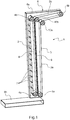
Figure 1 est une vue en perspective du convoyeur à bande de matière pulvérulente ou granuleuse en vrac selon la présente invention ; - la
Figure 2 est une vue de côté du convoyeur à bande de laFigure 1 ; et - la
Figure 3 est un agrandissement de laFigure 2 au niveau des deux tambours rotatifs inférieurs du convoyeur à bande.
- the
Figure 1 is a perspective view of the conveyor belt of bulk powdery or granular material according to the present invention; - the
Figure 2 is a side view of the conveyor belt of theFigure 1 ; and - the
Figure 3 is an enlargement of theFigure 2 at the two lower rotary drums of the conveyor belt.
Si l'on se réfère aux
Le convoyeur à bande de matière pulvérulente ou granuleuse en vrac 1 comprend une première bande transporteuse sans fin 2 et une seconde bande transporteuse sans fin 3.The belt conveyor of pulverulent or
La première bande transporteuse 2 est apte à être entraînée en rotation par un premier tambour rotatif inférieur 4a et un premier tambour rotatif supérieur 4b.The
La seconde bande transporteuse 3 est apte à être entraînée en rotation par un second tambour rotatif inférieur 5a et un second tambour rotatif supérieur 5b.The
Le convoyeur à bande 1 comprend en outre un châssis 6 sur lequel les premier et second tambours inférieurs 4a, 5a et les premier et second tambours supérieurs 4b, 5b sont fixés en rotation, lesdits premier et second tambours inférieurs 4a, 5a et lesdits premier et second tambours supérieurs 4b, 5b étant entraînés en rotation par un ou plusieurs moteurs, qui peuvent notamment être des moteurs électriques, pneumatiques ou encore hydrauliques (non représentés aux
Il est à noter que, sur la
La paroi inférieure 6b du châssis 6 est disposée sous les premier et second tambours inférieurs 4a, 5a.The
La première bande transporteuse 2 comprend des tasseaux 7 répartis sur sa surface externe, chaque tasseau 7 s'étendant dans la direction transversale de la première bande transporteuse 2.The
La surface externe de la seconde bande transporteuse 3 est lisse.The outer surface of the
Il est à noter que la seconde bande transporteuse 3 pourrait également comprendre des tasseaux répartis sur sa surface externe, sans s'écarter du cadre de la présente invention.It should be noted that the
Les tasseaux 7 possèdent une forme rectiligne et relativement fine à section carrée ou rectangulaire, mais pourraient également prendre n'importe quelle forme, telle qu'une forme de chevron, sans s'écarter du cadre de la présente invention.The
L'espacement entre deux tasseaux 7 est régulier et dépend du produit véhiculé, selon sa densité et sa granulométrie. Pour une bande de largeur 400 mm, par exemple, et une hauteur de tasseau de 60 mm, l'espacement moyen pourra, pour des produits courants de densité 0,7, avoir un pas moyen de l'ordre de 250 mm.The spacing between two
Les première et seconde bandes transporteuses 2, 3 sont réalisées en au moins une matière plastique parmi les bandes commercialisées de façon standard ; caoutchouc naturel ou de synthèse, matières plastiques souples, polyéthylène, poly(chlorure de vinyle) (PVC), silicone.The first and
Les tasseaux 7 sont réalisés dans la même matière que la première bande transporteuse 2.The
La première bande transporteuse 2 et la partie inférieure 3a de la seconde bande transporteuse 3 sont inclinées par rapport à l'horizontale.The
L'inclinaison de la première bande transporteuse 2 et de la partie inférieure 3a de la seconde bande transporteuse 3 est identique et sensiblement de 90° par rapport à l'horizontale.The inclination of the
Il est à noter que ladite inclinaison pourrait également être comprise entre 85° et 90° par rapport à l'horizontale, sans s'écarter du cadre de la présente invention.It should be noted that said inclination could also be between 85 ° and 90 ° relative to the horizontal, without departing from the scope of the present invention.
Les première et seconde bandes transporteuses 2, 3 possèdent des sens de rotation opposés de telle sorte que la partie ascendante de la partie inférieure 3a de la seconde bande transporteuse 3 est disposée en regard de la partie ascendante de la première bande transporteuse 2, les tasseaux 7 de la première bande transporteuse 2 étant ainsi contigus à la surface externe de la seconde bande transporteuse 3 dans la région dans laquelle les parties ascendantes des première et seconde bandes transporteuses 2, 3 sont en regard, appelée par la suite région d'élévation de matière pulvérulente ou granuleuse.The first and
Le convoyeur à bande 3 comprend en outre des premier et second sols de glissement plats 8, 9 sur lesquels les première et seconde bandes transporteuses 2, 3 sont respectivement configurées pour glisser, lesdits premier et second sols de glissement plats 8, 9 étant disposés respectivement contre les surfaces internes des parties ascendantes des première et seconde bandes transporteuses 2, 3 dans la région d'élévation de matière pulvérulente ou granuleuse.The
Les premier et second sols de glissement sont fixés au châssis 6.The first and second sliding floors are attached to the
Les premier et second sols de glissement 8, 9 sont réalisées en au moins une matière parmi des métaux (par exemple, le fer, l'aluminium et/ou le cuivre) et leurs alliages, des matières plastiques (par exemple, le polyéthylène haute densité (PEHD) et/ou le poly(chlorure de vinyle) (PVC)) et des matériaux composites.The first and second slip lands 8, 9 are made of at least one of metals (eg, iron, aluminum and / or copper) and their alloys, plastics (for example, high polyethylene). density (HDPE) and / or polyvinyl chloride (PVC)) and composite materials.
L'utilisation de sols de glissement plats 8, 9 permet d'empêcher la déformation des bandes transporteuses 2, 3 lors du transport d'une matière pulvérulente ou granuleuse entre celles-ci.The use of flat sliding
Le convoyeur à bande 1 comprend en outre un rouleau de guidage inférieur 10a et un rouleau de guidage supérieur 10b configurés pour couder la seconde bande transporteuse 3 après la région d'élévation de matière pulvérulente ou granuleuse.The
Le rouleau de guidage supérieur 10b possède une hauteur légèrement inférieure à celle du premier tambour supérieur 4b de la première bande transporteuse 2, le rouleau de guidage 10a ayant une hauteur inférieure à celle du rouleau de guidage supérieur 10b.The
Le rouleau de guidage supérieur 10b est disposé contre la surface interne de la seconde bande transporteuse 3, tandis que le rouleau de guidage inférieur 10a est disposé contre la surface externe de la seconde bande transporteuse 3.The
Les rouleaux de guidage inférieur 10a et supérieur 10b sont fixés sur le châssis 6.The
Les deux rouleaux de guidage 10a, 10b permettent ainsi de créer un coude sur la seconde bande transporteuse 3 afin de créer une partie supérieure 3b de la seconde bande transporteuse 3 qui possède une faible inclinaison par rapport à l'horizontale.The two
Il est à noter que la partie supérieure 3b de la seconde bande transporteuse 3 pourrait également être horizontale ou descendante, sans s'écarter du cadre de la présente invention.It should be noted that the
La partie supérieure 3b de la seconde bande transporteuse 3 permet de transporter la matière pulvérulente ou granuleuse vers un collecteur ou le sommet d'un tas de matière pulvérulente ou granuleuse, une fois que la matière pulvérulente ou granuleuse a été élevée par l'action conjointe des deux bandes transporteuses 2, 3, comme cela sera décrit plus en détail à la
Si l'on se réfère à la
Les flèches représentées sur les premier et second tambours inférieurs 4a, 5a à la
Du fait que les tasseaux 7 de la première bande transporteuse 2 sont contigus à la surface externe de la seconde bande transporteuse 3 dans la région d'élévation de matière pulvérulente ou granuleuse, des compartiments 12 sont formés entre deux tasseaux 7 successifs de la première bande transporteuse 2 dans la région d'élévation de matière pulvérulente ou granuleuse, chaque compartiment 12 étant apte à recevoir de la matière pulvérulente ou granuleuse 11 afin de permettre son élévation entre les deux bandes transporteuses 2, 3. Le convoyeur à bande 1 permet ainsi le transport de la matière pulvérulente ou granuleuse 11 à un angle pouvant aller jusqu'à 90° sans abimer celle-ci, par emprisonnement de la matière pulvérulente ou granuleuse 11 dans les compartiments 12 formés entre les deux bandes transporteuses 2, 3 dans la région d'élévation de matière pulvérulente ou granuleuse, la seconde bande transporteuse 3 entraînant la matière pulvérulente ou granuleuse 1 et la première bande transporteuse 2 capturant et emprisonnant la matière pulvérulente ou granuleuse 11 par l'intermédiaire de ses tasseaux 7.Because the
L'espacement entre les tasseaux 7 étant régulier, les compartiments 12 formés entre les deux bandes transporteuses 2, 3 sont également réguliers, la quantité de matière pulvérulente ou granuleuse 11 transportée dans chaque compartiment 12 étant ainsi identique.Since the spacing between the
La matière pulvérulente ou granuleuse 11 peut ainsi tout d'abord être déchargée sur la paroi inférieure 6b du châssis 6 au niveau des premier et second tambours inférieurs 4a, 5a du convoyeur à bande 1, puis être élevée par l'action conjointe des deux bandes transporteuses 2, 3, avant d'être déchargée par la partie supérieure 3b de la seconde bande transporteuse 3 vers un collecteur tel qu'un silo ou une benne de camion.The pulverulent or
La vitesse de rotation de la seconde bande transporteuse 3 est supérieure à celle de la première bande transporteuse 2, afin qu'il ne puisse pas s'accumuler de matière, c'est-à-dire de poussières fines, entre la tête des tasseaux 7 et la seconde bande transporteuse 3, ce qui pourrait occasionner des bourrages.The speed of rotation of the
Il est à noter que la vitesse de rotation de la seconde bande transporteuse 3 pourrait également être identique à celle de la première bande transporteuse 2, sans s'écarter du cadre de la présente invention.It should be noted that the speed of rotation of the
Le second tambour inférieur 5a est disposé à une hauteur légèrement inférieure à celle du premier tambour inférieur 4a, ce qui permet à la matière pulvérulente ou granuleuse 11 de pouvoir être collectée très bas, pratiquement au niveau de la paroi inférieure 6b du châssis.The second
Le convoyeur à bande 1 comprend également un dispositif de balayeuse (non représenté sur les
Claims (9)
Applications Claiming Priority (1)
| Application Number | Priority Date | Filing Date | Title |
|---|---|---|---|
| FR1853690A FR3080614B1 (en) | 2018-04-26 | 2018-04-26 | BULK PULVERULENT OR GRANULAR MATERIAL BELT CONVEYOR |
Publications (1)
| Publication Number | Publication Date |
|---|---|
| EP3560860A1 true EP3560860A1 (en) | 2019-10-30 |
Family
ID=62684947
Family Applications (1)
| Application Number | Title | Priority Date | Filing Date |
|---|---|---|---|
| EP19171220.7A Withdrawn EP3560860A1 (en) | 2018-04-26 | 2019-04-25 | Conveyor belt for bulk powdered or granular material |
Country Status (2)
| Country | Link |
|---|---|
| EP (1) | EP3560860A1 (en) |
| FR (1) | FR3080614B1 (en) |
Citations (13)
| Publication number | Priority date | Publication date | Assignee | Title |
|---|---|---|---|---|
| US2539524A (en) * | 1945-08-04 | 1951-01-30 | Edmund Quincy Moses | Coacting belt conveyer |
| DE2614109A1 (en) * | 1975-04-02 | 1976-10-14 | Allis Chalmers Canada | HANDLING DEVICE FOR TRANSPORTING BULK GOODS |
| DE2631643A1 (en) * | 1976-07-14 | 1978-05-11 | Scholtz Ag Conrad | Conveyor for vertical transport of bulk goods - with enclosed conveying space formed by outer belt and inner belt with undulating edges |
| JPS57126329A (en) * | 1981-01-28 | 1982-08-06 | Ishikawajima Harima Heavy Ind Co Ltd | Continuous unloader |
| FR2506273A1 (en) * | 1981-05-21 | 1982-11-26 | Maschf Augsburg Nuernberg Ag | Material winning and crushing system - uses rotating drum with deflector vanes to accelerate and project material onto conveyor |
| JPS58114232U (en) * | 1982-01-26 | 1983-08-04 | 石川島播磨重工業株式会社 | Continuous unloader |
| JPH02106508A (en) * | 1988-10-12 | 1990-04-18 | Asahi Tec Corp | Belt conveyer with cleat |
| EP0498671A1 (en) * | 1991-02-08 | 1992-08-12 | Bridgestone Corporation | Belt conveyor system |
| JPH09255120A (en) * | 1996-03-25 | 1997-09-30 | Yoshino Gomme Kogyo Kk | Steeply inclined conveyor |
| ES1052082U (en) * | 2002-05-27 | 2002-11-01 | Lopez Joaquin Brito | Conveyor belts for unloading bulk material from ships. (Machine-translation by Google Translate, not legally binding) |
| JP2003226414A (en) * | 2002-02-05 | 2003-08-12 | Yoshino Rubber Industrial Co Ltd | Conveyor device |
| US20130008764A1 (en) * | 2011-07-08 | 2013-01-10 | Ksi Conveyors, Inc. | Vertical lift conveyor |
| US20160083188A1 (en) * | 2013-04-17 | 2016-03-24 | Paul Pribyl | Method And System For Discharging Swarf From A Conveyor |
-
2018
- 2018-04-26 FR FR1853690A patent/FR3080614B1/en not_active Expired - Fee Related
-
2019
- 2019-04-25 EP EP19171220.7A patent/EP3560860A1/en not_active Withdrawn
Patent Citations (13)
| Publication number | Priority date | Publication date | Assignee | Title |
|---|---|---|---|---|
| US2539524A (en) * | 1945-08-04 | 1951-01-30 | Edmund Quincy Moses | Coacting belt conveyer |
| DE2614109A1 (en) * | 1975-04-02 | 1976-10-14 | Allis Chalmers Canada | HANDLING DEVICE FOR TRANSPORTING BULK GOODS |
| DE2631643A1 (en) * | 1976-07-14 | 1978-05-11 | Scholtz Ag Conrad | Conveyor for vertical transport of bulk goods - with enclosed conveying space formed by outer belt and inner belt with undulating edges |
| JPS57126329A (en) * | 1981-01-28 | 1982-08-06 | Ishikawajima Harima Heavy Ind Co Ltd | Continuous unloader |
| FR2506273A1 (en) * | 1981-05-21 | 1982-11-26 | Maschf Augsburg Nuernberg Ag | Material winning and crushing system - uses rotating drum with deflector vanes to accelerate and project material onto conveyor |
| JPS58114232U (en) * | 1982-01-26 | 1983-08-04 | 石川島播磨重工業株式会社 | Continuous unloader |
| JPH02106508A (en) * | 1988-10-12 | 1990-04-18 | Asahi Tec Corp | Belt conveyer with cleat |
| EP0498671A1 (en) * | 1991-02-08 | 1992-08-12 | Bridgestone Corporation | Belt conveyor system |
| JPH09255120A (en) * | 1996-03-25 | 1997-09-30 | Yoshino Gomme Kogyo Kk | Steeply inclined conveyor |
| JP2003226414A (en) * | 2002-02-05 | 2003-08-12 | Yoshino Rubber Industrial Co Ltd | Conveyor device |
| ES1052082U (en) * | 2002-05-27 | 2002-11-01 | Lopez Joaquin Brito | Conveyor belts for unloading bulk material from ships. (Machine-translation by Google Translate, not legally binding) |
| US20130008764A1 (en) * | 2011-07-08 | 2013-01-10 | Ksi Conveyors, Inc. | Vertical lift conveyor |
| US20160083188A1 (en) * | 2013-04-17 | 2016-03-24 | Paul Pribyl | Method And System For Discharging Swarf From A Conveyor |
Non-Patent Citations (1)
| Title |
|---|
| JORGENSEN CONVEYORS: "Introducing The New UVS-ECOLOGIC Control from Jorgensen Conveyors!", 17 April 2018 (2018-04-17), pages 1, XP055539409, Retrieved from the Internet <URL:https://www.jorgensenconveyors.com/wp-content/themes/jorgensen/assets/brochures/UVS-EcoLogic-Control-sales-flyer-8-14-HR-Rev-02-17.pdf> [retrieved on 20190108] * |
Also Published As
| Publication number | Publication date |
|---|---|
| FR3080614B1 (en) | 2021-03-05 |
| FR3080614A1 (en) | 2019-11-01 |
Similar Documents
| Publication | Publication Date | Title |
|---|---|---|
| FR2950614A1 (en) | Chain for unloading pallet transporting cage of grape, has turning guide that is in form of circle arc that ensures rotation of food product case between inlet and outlet and emptying case at top of press | |
| CA2740268C (en) | Belt conveyor for oilseeds | |
| WO2009130295A1 (en) | Equipment for handling packs of tyres | |
| EP1564164B1 (en) | Troughed belt conveyor | |
| EP3560860A1 (en) | Conveyor belt for bulk powdered or granular material | |
| EP2090530B1 (en) | Belt conveyor with widely-spaced support stations | |
| FR2503095A1 (en) | DEVICE FOR THE PACKAGING OF LARGE-LENGTH ARTICLES, IN PARTICULAR TRANSPORT BANDS | |
| EP2406155A1 (en) | Transversely deformable endless conveyor belt for a conveyor device | |
| EP2213598B1 (en) | Mail processing machine equipped with means for jogging mail articles against referencing walls | |
| FR2933964A1 (en) | Lifting conveyor for transporting e.g. fish, in agri-food industry, has conforming unit formed of guiding members, rollers, endless belt and pads, to conform carrier belt upper side into curved configuration on portion of ascending section | |
| FR3123905A1 (en) | Device for unloading a vehicle transporting bulk material, associated assembly and method | |
| EP2536590B1 (en) | Dump truck skip having a bottom wall covered with a shock-absorbing endless belt, and truck thus fitted | |
| FR2998444A1 (en) | OFF-GROUND PLANT CULTIVATION INSTALLATION | |
| EP0046425B1 (en) | Conveyor belt arrangement for conveying concrete | |
| JP2016088684A (en) | Chain-driven type flat belt conveyer | |
| FR2489796A1 (en) | Machine for picking up e.g. powdered sugar from silo floor - uses pair of screws to feed bucket elevator which imparts drive via screw fairings | |
| FR2775268A1 (en) | Endless belt for conveyor | |
| FR2670472A1 (en) | Belt conveyor for transferring bulk products vertically or along a steep gradient | |
| CA3153434A1 (en) | System for accompanying a divided material and the associated process | |
| EP1396290A1 (en) | Method and device for automatically and morphologically sorting of substantially spherical objects | |
| BE844844A (en) | BUCKET CARRIER | |
| BE1009636A3 (en) | Packing crate | |
| EP1603383A1 (en) | Device for filling a bin or similar | |
| FR3041619A1 (en) | CONVEYOR WITH A DEEP SELF-SUPPORTING AUGER STRIP AND USE OF SUCH A STRIP | |
| FR2509116A1 (en) | Fruit transporter for grape harvester - has transverse cylindrical drum with side flanges over which outer run of double run belt passes |
Legal Events
| Date | Code | Title | Description |
|---|---|---|---|
| PUAI | Public reference made under article 153(3) epc to a published international application that has entered the european phase |
Free format text: ORIGINAL CODE: 0009012 |
|
| STAA | Information on the status of an ep patent application or granted ep patent |
Free format text: STATUS: THE APPLICATION HAS BEEN PUBLISHED |
|
| AK | Designated contracting states |
Kind code of ref document: A1 Designated state(s): AL AT BE BG CH CY CZ DE DK EE ES FI FR GB GR HR HU IE IS IT LI LT LU LV MC MK MT NL NO PL PT RO RS SE SI SK SM TR |
|
| AX | Request for extension of the european patent |
Extension state: BA ME |
|
| STAA | Information on the status of an ep patent application or granted ep patent |
Free format text: STATUS: REQUEST FOR EXAMINATION WAS MADE |
|
| 17P | Request for examination filed |
Effective date: 20200319 |
|
| RBV | Designated contracting states (corrected) |
Designated state(s): AL AT BE BG CH CY CZ DE DK EE ES FI FR GB GR HR HU IE IS IT LI LT LU LV MC MK MT NL NO PL PT RO RS SE SI SK SM TR |
|
| GRAP | Despatch of communication of intention to grant a patent |
Free format text: ORIGINAL CODE: EPIDOSNIGR1 |
|
| STAA | Information on the status of an ep patent application or granted ep patent |
Free format text: STATUS: GRANT OF PATENT IS INTENDED |
|
| INTG | Intention to grant announced |
Effective date: 20211221 |
|
| STAA | Information on the status of an ep patent application or granted ep patent |
Free format text: STATUS: THE APPLICATION IS DEEMED TO BE WITHDRAWN |
|
| 18D | Application deemed to be withdrawn |
Effective date: 20220503 |