EP3559988B1 - Carrier substrate for electric components, and method for manufacturing a carrier substrate - Google Patents
Carrier substrate for electric components, and method for manufacturing a carrier substrate Download PDFInfo
- Publication number
- EP3559988B1 EP3559988B1 EP17825198.9A EP17825198A EP3559988B1 EP 3559988 B1 EP3559988 B1 EP 3559988B1 EP 17825198 A EP17825198 A EP 17825198A EP 3559988 B1 EP3559988 B1 EP 3559988B1
- Authority
- EP
- European Patent Office
- Prior art keywords
- layer
- metal layer
- carrier substrate
- recesses
- primary
- Prior art date
- Legal status (The legal status is an assumption and is not a legal conclusion. Google has not performed a legal analysis and makes no representation as to the accuracy of the status listed.)
- Active
Links
Images








Classifications
-
- H—ELECTRICITY
- H10—SEMICONDUCTOR DEVICES; ELECTRIC SOLID-STATE DEVICES NOT OTHERWISE PROVIDED FOR
- H10W—GENERIC PACKAGES, INTERCONNECTIONS, CONNECTORS OR OTHER CONSTRUCTIONAL DETAILS OF DEVICES COVERED BY CLASS H10
- H10W40/00—Arrangements for thermal protection or thermal control
- H10W40/20—Arrangements for cooling
- H10W40/25—Arrangements for cooling characterised by their materials
- H10W40/255—Arrangements for cooling characterised by their materials having a laminate or multilayered structure, e.g. direct bond copper [DBC] ceramic substrates
Definitions
- the present invention relates to a carrier substrate for electrical, in particular electronic, components and a method for producing a carrier substrate.
- Carrier substrates are known, for example, as printed circuit boards or circuit boards. Electrical or electronic components and conductor tracks are typically arranged on one component side of the carrier substrate, whereby the electrical or electronic components and the conductor tracks can be connected together to form electrical circuits.
- carrier substrates that have an insulating layer with high electrical insulation strength for the electrical insulation of the individual electrical components and conductor tracks, such as a primary layer made of ceramic, have proven to be particularly advantageous.
- the electrical components When these carrier substrates are in operation, particularly when used in power electronics, the electrical components are typically subjected to such stress that they heat up and local heat sources form on the component side.
- the state of the art therefore includes heat sinks or cooling structures that are usually attached, e.g. soldered, to a cooling side opposite the component side, which is designed, for example, as a copper layer or copper base adjacent to the primary layer.
- the thermomechanical behavior of the carrier substrate during operation can disadvantageously lead to mechanical stresses in the carrier substrate.
- the JP-H 09260546 discloses a carrier substrate for electrical components, wherein a metal layer is provided, on the side of which facing the base body of the carrier substrate several evenly distributed recesses are formed.
- a carrier substrate is known whose metallization has a stepped course on the peripheral edge such that a recess is formed between the base body and the metallization on the peripheral outermost edge of the metallization.
- the WO 2013 186 267 A1 describes a mounting carrier for semiconductor chips, which has a second main surface provided for the mounting of semiconductor chips and a first main surface opposite the second main surface.
- the mounting carrier also has a mounting body, wherein the mounting body has a first metallization on the side facing the first main surface and the first main surface has a structure with a plurality of columnar structural elements.
- a carrier substrate for electrical components, in particular electronic components wherein the carrier substrate has a primary layer made of ceramic and at least one metal layer bonded to the primary layer, wherein the at least one metal layer has at least one, preferably several, recesses on the side facing the primary layer.
- the metal layer according to the invention has the advantage that the recesses influencing the thermal or thermomechanical behavior are arranged on the side facing the primary layer, in particular directly adjacent to the primary layer.
- the surface provided on the component side for connecting electrical or electronic components is not impaired or restricted, but is fully available to the user for attaching electronic components, wire bonds and/or terminals for supplying and discharging various electrical currents and voltages.
- the recesses have a positive effect on the carrier substrate by increasing the carrier substrate's resistance to thermal shock by up to 10 times, depending on their location, or by distributing mechanical stresses, so that, for example, local mechanical stress peaks in the edge area of the carrier substrate, in particular those originating from the primary layer, can be counteracted.
- These recesses can also be designed to be comparatively small in terms of their volume. This allows the arrangement of the recesses directly in the area in which the primary layer adjoins the metal layer and in which the greatest thermomechanically induced stresses arise.
- the manufacturing process can dispense with the introduction of the recess into the metal layer from the component side to the primary layer.
- the carrier substrate only has the primary layer and at least one metal layer, ie the carrier substrate is designed in two layers.
- the recesses facing the primary layer offer greater degrees of freedom in terms of their design, i.e. shape and arrangement, and the number of recesses introduced, since they are independent of the component side or surface, in particular independent of specifications by the component side.
- several rows of recesses can run from the edge of the metal layer into its central area.
- the recesses can extend over the entire thickness of the metal layer, i.e. be continuous, or only partially etched there, so that the metal layer is only locally weakened at certain points, preferably at the edge.
- the metal layer is a structured metal surface, such as a conductor track, on which electrical or electronic components can be mounted to form a circuit.
- the recesses are etched into the metal layer.
- the recesses are etched into the metal layer in particular before the metal layer is joined to the primary layer and then the metal layer is aligned during joining in such a way that the recesses lie on the primary side or border on the primary layer.
- the recesses are filled with a filling material, wherein the filling material in its intended state has in particular a lower coefficient of expansion and/or a higher modulus of elasticity than a material from which the metal layer is made.
- the filling material has a coefficient of linear expansion smaller than copper, i.e. ⁇ ⁇ 16.5 x 10 -6 K -1 , measured at room temperature.
- the filling material can advantageously be used to support or enable a subsequent joining process in which the carrier substrate is brought into its intended state by means of a material-to-material connection between the filling material and the metal layer on the one hand and between the filling material and the primary layer on the other.
- the filler material is selected in such a way that a lower combined coefficient of expansion (CTE) is established locally in the area of the edge profile, which partially shifts the thermomechanical stresses caused by the joining temperature during cooling after the joining process from the interface between the primary layer and the metal layer into the metal layer, in which the thermomechanical stresses can in turn be better reduced during cooling.
- CTE combined coefficient of expansion
- Possible filler materials include, for example, particle-filled soft solder, hard solder or active solder which contain 10 - 64 vol.%, preferably 20 - 50 vol.% and particularly preferably 30 - 50 vol.% of ceramic or metal particles with the properties described above, such as SiC, AIN, Al 2 O 3 , HPSX, BeO, Si 3 N 4 , ZnO, TiN, B 4 C, Mo, W, Cr, Ta or Nb.
- the primary layer has in particular an insulation layer with high electrical insulation strength, preferably of more than 5 kV/mm, particularly preferably of more than 10, 20 or even more than 30 kV/mm and/or with high thermal conductivity, preferably more than 10 W/mK, particularly preferably more than 20 or even more than 60 W/mK, such as technical ceramics or organic insulation materials filled with thermally conductive materials.
- an insulation layer with high electrical insulation strength preferably of more than 5 kV/mm, particularly preferably of more than 10, 20 or even more than 30 kV/mm and/or with high thermal conductivity, preferably more than 10 W/mK, particularly preferably more than 20 or even more than 60 W/mK, such as technical ceramics or organic insulation materials filled with thermally conductive materials.
- the side of the metal layer facing the component side, in particular the structured metal surface has a smooth, i.e. recess-free, surface at least in some areas.
- the recesses are designed such that a closed surface side of the structured metal surface facing the component side is larger than the contact surfaces via which the structured metal surface is in contact with or connected to the primary layer. It is also conceivable that the recesses are designed as hole-like and/or blind-hole-like, i.e. the recesses penetrate through the metal layer or open or end, preferably in the shape of a dome or cupola, in the interior of the metal layer.
- hole-like recesses and blind-hole-like bores are realized in the metal layer, wherein the number of hole-like recesses is smaller than the number of blind-hole-like recesses. Furthermore, it is preferably provided that in a projection direction or orientation running perpendicular to the main extension plane of the carrier substrate, no recesses or fewer recesses are arranged below a location or connection location provided for the component compared to the rest of the metal layer.
- the recess is arranged on the edge profile of the metal layer.
- the edge profile of the metal layer is preferably defined by a line along which the metal layer ends its direct contact with the primary layer.
- the edge profile, ie the edge line, or its surface is enlarged by the recesses, whereby mechanical stresses occurring during operation, in particular those originating from the primary layer, can be better distributed.
- the edge profile is in particular an outer circumference the edge layer in a plane running parallel to the main extension plane of the carrier substrate.
- the recess is let into an edge of the metal layer adjacent to the primary layer.
- the recess in the edge profile causes a contour that is set back by a maximum of one indentation depth.
- the average indentation depth ie the indentation depth averaged over the recesses in the edge profile, takes on a value between 50 ⁇ m and 1000 ⁇ m, preferably between 100 ⁇ m and 800 ⁇ m and particularly preferably between 150 ⁇ m and 600 ⁇ m.
- a ratio of a depth of the recess measured in the projection direction to the indentation depth assumes a value between 0.2 and 1.2, preferably between 0.3 and 1.0 and particularly preferably between 0.4 and 0.8.
- the edge region is the region in which 60% - 100%, preferably 80% - 100% of all recesses are arranged.
- several recesses in particular several recesses arranged next to one another, form a meandering, postage stamp-shaped and/or sawtooth-shaped edge profile of the metal layer, wherein in particular the meandering, postage stamp-shaped and/or sawtooth-shaped edge profile extends over the entire edge profile of the metal layer. It is also conceivable that the meandering, postage stamp-shaped and/or sawtooth-shaped edge profile of the metal layer extends only over a partial area of the entire edge profile of the metal layer or that several partial areas adjoin one another at a distance from one another as seen in the circumferential direction.
- the edge profile can also have irregular recesses, i.e., for example, small and large recesses that are mixed or arranged alternately with one another, or that are wavy, rectangular, parallelogram-shaped or jagged.
- a closed strip of the metal layer is formed along the edge profile, with the strip having the meandering, postage stamp-shaped and/or sawtooth-shaped edge profile, particularly towards one side.
- additional needle, dome or pin structures are arranged within the recesses in the edge profile, which connect the primary layer to the metal layer in order to homogenize the mechanical stress distribution or to distribute it over a larger area.
- the recess prefferably be designed as a curvature, in particular as a dome-like or partially dome-like curvature.
- the curvature is directed towards the side of the attached metal layer facing away from the primary layer. This advantageously prevents the recesses from appearing on the side of the metal layer facing away from the primary layer.
- the side of the metal layer facing away from the primary layer can thus be used entirely for components.
- the recesses in the central region of the metal layer form cavities between the metal layer and the primary layer.
- the metal layer forms an overhang, for example in a direction running perpendicular to the main extension plane.
- the recess to be designed to be oval, diamond-shaped, diamond-shaped or groove-shaped in a cross-section, in particular in a plane running parallel to the main extension plane.
- the recess has an average depth in a direction perpendicular to the main extension plane, which in relation to the smallest opening width of the recess, for example a diameter for a circular recess or a width of a trench-shaped recess, preferably assumes a value between 0.2 and 1.2, preferably between 0.3 and 1.0 and particularly preferably from 0.4 to 0.8. It is particularly preferred that the recesses are as small as possible with regard to the thermal behavior of the carrier substrate. It is also conceivable that the recesses are distributed over the entire metal layer. In this case, it is conceivable that the depths are distributed statistically or arbitrarily over the entire metal layer.
- the metal layer in the central region has a first partial region and a second partial region, wherein the number of recesses and/or the depth or size in the first partial region differs from the number of recesses and/or their depth or size in the second partial region.
- the first partial region and the second partial region are designed depending on the carrier substrate or its field of application.
- the average number and/or average depth of the recesses changes continuously across the metal layer.
- the number and/or depth of the recess increases or decreases in the direction of the edge of the metal layer.
- the ratio between the depth of the recesses and the thickness of the structured metal surface is between 2.5% and 70%, preferably between 5% and 60% and particularly preferably between 10% and 55%.
- the ratio of the depth of the recesses to the thickness of the metal layer refers to metal layer thicknesses between 200 ⁇ m and 2000 ⁇ m, preferably between 250 ⁇ m and 1500 ⁇ m and particularly preferably between 300 ⁇ m and 1000 ⁇ m.
- All other recesses that run parallel to the continuous, dome-shaped depression can be designed to be continuous or as several discrete recesses lying next to one another.
- a second distance of all further recesses from the recess has values between 100 ⁇ m and 1000 ⁇ m, preferably 110 ⁇ m and 600 ⁇ m and particularly preferably 150 ⁇ m and 400 ⁇ m.
- the depth of the recesses and the depth of the further recess is smaller than the thickness of the metal layer and preferably have values between 2.5% and 70%, preferably between 5% and 60% and particularly preferably between 10% and 55% of the metal layer thickness.
- recesses on the second side are arranged in a direction perpendicular to the main plane of extension, essentially congruent with or offset from the recesses on the first side of the intermediate layer.
- a comparatively resistant metal layer is provided, since local weakening of the metal layer is avoided.
- a sufficiently large intermediate layer can be provided beneath components, via which the heat from the components acting as a heat source can be effectively transported to the cooling side during operation.
- the intermediate layer has grooves, in particular etched grooves, lying opposite one another in an area adjacent to the edge profile on the first and second sides.
- the recess is let into cooling structures or parts of cooling structures that protrude from the primary layer and/or secondary layer in a direction parallel to the main extension plane.
- the cooling structure comprises a base body and a web region with webs running perpendicular to the main extension plane.
- the recess preferably encloses or surrounds an edge of the first primary layer and/or the secondary layer, in particular the edge of the primary layer and/or the secondary layer that faces the cooling structure, i.e. the recess forms a closed trench or a closed bead that surrounds the edge in the main extension plane.
- the metal layer is folded prior to joining.
- recesses are specifically made, preferably exclusively, on one side in the metal layer and then, by folding, the intermediate layer is provided with recesses that face the primary layer and the secondary layer in the manufactured state. This advantageously makes it possible to dispense with the complex etching of recesses on both sides in the metal layer.
- the recesses are etched into the metal layer in such a way that the recesses in the folded state are arranged essentially congruent with one another or offset from one another in a direction running perpendicular to the main extension plane.
- two or more sub-substrates separately in a first step using the joining methods already mentioned, such as the primary layer with the structured metal surface and part of the metallic intermediate layer, as well as the secondary layer with part of the metallic intermediate layer and the cooling structure.
- These at least two sub-substrates or individual laminates are joined to the substrate according to the invention in at least one further, e.g. second, joining step, using common joining processes.
- common joining processes such as DCB process, brazing, soft soldering, diffusion welding or a sintering process.
- the metal layer is etched on both sides, preferably simultaneously or with temporal overlap.
- narrower structures or recesses can be realized between the metal surfaces of the layout or the structured metal surfaces.
- thicker metal layers can be structured because, unlike in the prior art, they can be etched on both sides and congruent with one another. Congruent is to be understood as meaning that the recesses are arranged in alignment with one another with regard to their center, while the recesses can have different widths. It is preferably provided that the width of the iso-trench assumes a value that corresponds to a multiple of the thickness of the metal layer, preferably 2-10 times, particularly preferably 2-5 times the thickness of the metal layer.
- the thermal shock resistance can be increased by 5 to 10 times.
- a carrier substrate 1 for electrical components 13 is shown schematically in a sectional view.
- This is preferably a ceramic-containing carrier substrate 1 that is advantageous for special applications.
- the carrier substrate 1 has a component side 4 on which a metal layer, for example made of copper or aluminum, is provided for electrical components 13 or modules in the form of structured metal surfaces 2.
- a metal layer for example made of copper or aluminum
- the carrier substrate 1 can be virtually broken down into a primary substrate, a secondary substrate and preferably into a virtual intermediate substrate or part of an intermediate layer located therebetween, the primary substrate also comprising part of the metal layer and the intermediate layer in addition to the primary layer and the secondary substrate comprising part of the cooling structure and the intermediate layer.
- a thermomechanical symmetry between the primary substrate and the secondary substrate is sought, ie the thermal expansion coefficient (CTE) of both substrates should preferably be the same or at least similar, for example within a tolerance of +/- 20% or preferably +/- 10%, particularly preferably +/- 5%.
- the edge profile 32 of the metal layer, in particular of the structured metal surface 2 is profiled or structured on the side facing the primary layer 10, in particular on an edge.
- the edge profile 32 is advantageously designed to distribute the mechanical stresses that occur.
- the structured edge profile 32 is formed by recesses 5, in particular etched recesses 5, on the side of the metal layer facing the primary layer 10.
- the recesses 5 do not extend to the component side of the structured metal surface 2.
- the recesses 5 have a depth T of between 10% and 70% of the layer thickness MD of the structured metal surface 2.
- the contact side of the metal layer facing the primary layer 10 is indented by an indentation depth ET to the outermost edge profile 35 of the metal layer.
- the average indentation depth ET here assumes a value between 20 ⁇ m and 600 ⁇ m, preferably between 50 ⁇ m and 500 ⁇ m and particularly preferably between 200 ⁇ m and 400 ⁇ m.
- the intermediate layer 15 arranged between the primary layer 10 and the secondary layer 20 and designed as a metal layer has a structured edge profile 32, which is realized in particular by several etched recesses 5 on the side facing the primary layer 10 and/or the secondary layer 20 or their edge profiles of the intermediate layer 15.
- the contact side of the metal layer facing the primary layer 10 and/or the secondary layer 20 is recessed by a further recess depth ET to the outermost Edge profile 35 of the metal layer is indented. It is conceivable that the indentation depth ET of the structured metal surface 2 and the further indentation depth ET of the intermediate layer 15 essentially correspond to one another or differ.
- the further indentation depth ET on the side of the intermediate layer 15 facing the secondary layer 20 and the indentation depth ET on the side of the intermediate layer 15 facing the primary layer 10 correspond to one another or differ.
- the recesses 5 in the structured metal surface 2 and the recesses 5 in the intermediate layer are designed to be congruent with one another in a projection direction or orientation P running perpendicular to the main extension plane of the carrier element 1, or are offset from one another.
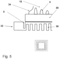
- a metallic cooling structure 30 connected to the secondary layer 20 on the cooling side 6 has an edge profile 32 structured by recesses 5.
- the indentation depth ET of the recesses 5 in the structured metal surface 2 and/or the further indentation depth ET of the recesses 5 in the intermediate layer 15 corresponds to an indentation depth ET in the cooling structure 30. It is also conceivable that the respective indentation depths are adapted to the individual application for which the carrier substrate 1 is intended.
- the structured metal surfaces 2, the metallic intermediate layer 15 and the cooling structure 30 are made of the metals Cu, Al, Mo, W, Ag, of alloys or composite materials of the metals mentioned, of special alloys such as Invar or Kovar or of composite materials of the metals mentioned filled with ceramic particles.
- the structured metal surfaces 2, the metallic intermediate layer 15 and the cooling structure 30 are made of copper or of aluminum or alloys and/or composite materials containing Cu and/or Al.
- the Primary layer 10 comprises Al 2 O 3 , ZrO 2 conversion-strengthened Al 2 O 3 , Si 3 N 4 , AIN, SiC, HPSX and/or BeO.
- the secondary layer 20 is preferably made of one of the aforementioned ceramics or molybdenum.
- Figure 2 is an edge profile 32 of the structured metal surface 2, the intermediate layer or cooling structure from the Figure 1 In particular, it is a meandering edge profile extending over the entire edge profile 32.
- a reduced top view of the carrier substrate 1 is shown in addition to the respective sectional views.
- a cutting line is shown as a dashed line, which can be assigned to the respective sectional view.
- FIGS 3a and 3b A second preferred and a third preferred embodiment of the intermediate layer 15 of an exemplary carrier substrate 1 according to the present invention are shown. It is conceivable that the intermediate layers 15 of the Figures 3a and 3b in a second and a third preferred embodiment of the carrier substrate 1, the intermediate layer 15 from Figure 1 can be replaced. In particular, in the case of the intermediate layers 15 from the Figures 3a and 3b provided that the metal layer designed as intermediate layer 15 has, in addition to the structured edge profile 32, recesses 5, in particular dome-shaped recesses 5, on the side facing the primary layer 10 and/or the secondary layer 20 in a central region 31.
- the recesses 5 are designed in such a way that, together with the primary layer 10 and/or the secondary layer 20, they form a cavity between the metal layer and the primary layer 10 and/or the secondary layer 20.
- the dome-shaped recesses 5 have a substantially circular cross-section, the diameter of which is between 100 ⁇ m and 1000 ⁇ m, preferably between 110 ⁇ m and 800 ⁇ m and particularly preferably between 150 ⁇ m and 600 ⁇ m. It is conceivable that the recesses 5 all have substantially the same diameter or that the sizes for the diameters are distributed statistically or randomly. Alternatively or additionally, it is conceivable that holes are let into the intermediate layer 15, which lead from the primary layer 10 to the secondary layer 20.
- both recesses 5 and hole-like recesses ie those that penetrate through the intermediate layer, are let into the intermediate layer 15, the ratio between hole-like recesses and blind hole-like recesses being less than 1, equal to 1 or greater than 1.
- recesses 5 are made on one side of a metal layer and then the metal layer is folded to form the intermediate layer 15.
- the folded metal layer forms a fold line FL and the recesses 5 are located on opposite sides of the intermediate layer 15.
- the recesses 5 on the first side 41 facing the primary layer 10 are arranged congruently with the recesses 5 on the second side 42 facing the secondary layer 20.
- the recesses 5 on the side facing the primary layer 10 are offset from the recesses 5 on the side facing the secondary layer 20 along a direction parallel to the main extension plane.
- the intermediate layers 15 from the Figures 3a and 3b It is provided that the edge profile 32 protrudes in a direction parallel to the main extension plane relative to the primary layer 10 and/or the secondary layer 20. As a result, the protruding section of the intermediate layer 15 can advantageously provide a contact element 16 with which a current can be introduced into the intermediate layer 15.
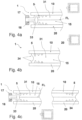
- FIGS 4a and 4b A fourth preferred and a fifth preferred embodiment of the intermediate layer 15 of an exemplary carrier substrate 1 according to the present invention are shown. It is conceivable that the Intermediate layers 15 of Figures 4a and 4b in a fourth and a fifth preferred embodiment of the carrier substrate 1, the intermediate layer 15 from Figure 1 is replaced in each case. In this case, the intermediate layer 15 is provided with a recess 5 within the intermediate layer 15.
- a hollow chamber 33 can be produced, for example, by etching two recesses 5 into a metal layer and then folding the metal layer to form the cavity within the intermediate layer 15 in such a way that the two recesses 5 are arranged congruently with one another on the folding side or along the folding line FL in the projection direction or orientation P.
- the two recesses 5 forming the cavity can, for example, be groove-shaped and/or dome-shaped.
- the intermediate layer 15 has a thickening 17 in the protruding section, which is provided for forming a contact element 16.
- the thickening 17 can be realized by an etching trench running parallel to the edge profile 32 of the intermediate layer 15, which is arranged on the side of the intermediate layer 15 facing the primary layer 10 and/or on the side of the intermediate layer 15 facing the secondary layer 20. It is also conceivable that two etching trenches are let into the metal layer and the thickening 17 is realized on the edge profile of the intermediate layer 15 by subsequently folding the metal layer. In the Figure 4b the edge profile 32 of the intermediate layer 15 is curved inwards.
- Such a stepped edge 34 can be realized, for example, by eroding the side surface of the intermediate layer 15, which faces neither the primary layer 10 nor the secondary layer 20, or in the case of a foldable intermediate layer 15 with a stepped edge profile, by etching.
- opposite edges of the intermediate layer 15 are provided with recesses of different widths, so that after folding in a direction perpendicular to the main extension plane, a stepped edge profile is formed on the side wall of the intermediate layer 15 It is also conceivable that further etching takes place in the area that forms the folding edge in the finished state or that immediately borders on it, in order to avoid mechanical stresses that would otherwise arise during later folding.
- the edge profile 32 of the intermediate layer 15 is designed such that the intermediate layer 15 has a section protruding from the primary layer 10 and/or the secondary layer 20 on one side and an inwardly curved edge region, i.e. a stepped edge 34, on the opposite side.
- a metal layer for a further preferred carrier substrate 1 is shown.
- the recess 5 is arranged on the side of the metal layer designed as a cooling structure 30 facing the secondary layer 20 and/or the primary layer 10.
- the recess 5 is arranged offset from the primary layer 10 and/or secondary layer 20 in a direction running parallel to the main extension plane, with the cooling structure 30 protruding from the primary layer 10 and/or the secondary layer 20.
- the recess is designed as an expansion joint in order to prevent the thermal expansion of the cooling structure 30 from causing mechanical stresses in the entire carrier substrate 1.
- FIG. 6 different arrangements of the recesses 5 in the metal layer are shown. Different cross-sectional shapes and arrangements in patterns are conceivable. In addition to circular cross-sections, a rectangular, a diamond-shaped, a wave-shaped and/or a triangular cross-section is also conceivable (first and second row). In addition, the Figure 6 Embodiments in which circular cross-sections with different diameters are arranged in different patterns (second and third row). Preferably, the circular cross-sections with different diameters arranged offset from each other.
- FIG. 7 A method for producing a recess 5 is shown schematically as an example. It is provided that the metal layer is etched on both sides, ie an etching process takes place both on the side of the metal layer adjacent to the primary layer 10 in the manufactured state and on the opposite side, in particular the intermediate layer 15. As the Figure 7 As can be seen, the recess 5 on the side facing the primary side 10 is etched first and then an iso-trench 7, which is intended in particular for forming a conductor track, is etched. It is also conceivable that these etching processes take place simultaneously or overlapping in time. By etching on both sides, it is also advantageously possible to accelerate the entire manufacturing process of the carrier substrate 1 and to create narrow iso-trenchs 7.
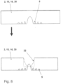
- FIG 8 Another method for producing a recess is shown schematically as an example. The method essentially corresponds to that of Figure 7 There is, however, a difference in the dimensions of the opposing etchings. It is preferably provided that the etching process on the side of the metal layer that is in contact with the primary layer 10 in the manufactured state is less intensive than the etching process on the opposite side. As a result, the recess 5 on the side associated with the primary layer 10 is smaller than that on the opposite side. By having the opposing etchings dimensioned differently, it is advantageously possible to implement a step etching with which the thermal shock resistance can be improved by a factor of between 5 and 10.
- a carrier substrate 1 according to an eighth exemplary embodiment of the present invention is shown in a detailed view.
- the Figure 8 The carrier substrate 1 shown comprises a closed etching trench 8, which extends parallel to the edge of the carrier substrate 1.
- the carrier substrate 1 also comprises an input channel 21 and an output channel 22 which are let into the metal layer and which connect the closed etching trenches 8 to an environment surrounding the carrier substrate 1.
- Via the input channel 21 it is advantageously possible to introduce filler material into the closed etching trenches 8 after the primary layer 10 has been joined to the metal layer.
- the input channel 21 can advantageously be used to fill the closed etching trench 8 or further recesses 5 with functional materials, e.g. organic materials, inorganic binders or particle-filled materials. Filling after joining is particularly positive because the recesses 5 cannot be filled with a filler material before joining because they are not resistant to the temperature development that occurs during joining.
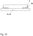
- the Figure 10 shows a further carrier substrate 1 according to the eighth preferred embodiment of the present invention. It shows the carrier substrate 1 from Figure 9 in a sectional view, wherein the recesses 5 are already filled with the filling material 38 before joining.
- the Figure 11 shows a sectional view through a metal layer 2, 15, 30 for a carrier substrate 1 according to a ninth embodiment of the present invention.
- a continuous trench-shaped depression is provided as the first recess 51, which runs parallel to the edge profile 35 of the metal layer 2, 15, 30 and ends in the metal layer 2, 15, 30 like a dome.
- the person skilled in the art understands the first recess 51 to mean in particular the first recess 5 let into the metal layer as seen from the edge profile 35 and spaced from the edge profile 35, or a first group of such recesses.
- one or more continuous first recesses 51 can be made next to one another in the metal layer 2, 15, 30 parallel to the edge profile 35 of the metal layer 2, 15, 30.
- the trench-shaped depression in the metal layer 2, 15, 30 has a first distance A from the edge profile 35 of the metal layer 2, 15, 30 from 100 ⁇ m to 1000 ⁇ m, preferably 110 ⁇ m to 600 ⁇ m and particularly preferably from 150 ⁇ m to 400 ⁇ m.
- All further recesses 52 which run parallel to the continuous fork-shaped depression can be designed to be continuous or as several discrete recesses lying next to one another.
- a second distance C of all further recesses 52 to the first recess 51 preferably has a value between 100 ⁇ m and 1000 ⁇ m, preferably between 110 ⁇ m and 600 ⁇ m and particularly preferably between 150 ⁇ m and 400 ⁇ m.
- the depth of the first recesses T 51 and the depth of the further recess T 52 is smaller than the thickness of the metal layer and preferably have values between 2.5% and 70%, preferably between 5% and 60% and particularly preferably between 10% and 55% of the metal layer thickness.
- a metal layer 2, 15, 30 is shown for a carrier substrate 1 according to a tenth and eleventh embodiment of the present invention.
- Discrete first recesses 51 are provided here, which are arranged in a row parallel to the edge profile 35 of the metal layer 2, 15, 30.
- the first recesses 51 preferably have a first distance A from the edge profile 35 of the metal layer 2, 15, 30 of 100 ⁇ m to 1000 ⁇ m, preferably 110 ⁇ m to 600 ⁇ m and particularly preferably 150 ⁇ m to 400 ⁇ m.
- this row of first recesses 51 is followed by a row of further recesses 52 or even several rows of discrete further recesses 52 that are continuous in the direction of the main extension planes.
- the second distance C of the first recesses 51 to the further recess 52 is preferably 50 ⁇ m to 1000 ⁇ m, preferably 80 ⁇ m to 600 ⁇ m and particularly preferably 100 ⁇ m to 400 ⁇ m. Furthermore, it is preferably provided that the center points of the first recess 51 and the further recesses 52 are arranged parallel to the main extension plane of the metal layer, along a line which, according to the tenth embodiment (see 10a), is perpendicular to the edge profile 35 of the metal layer 2, 15, 30 or, according to the eleventh embodiment, forms an angle ⁇ to the edge profile 35 of the metal layer 2, 15, 30 which is smaller than 90° (see 12b).
- the depth T 51 of the first recesses and the depth the further recesses T 52 is smaller than the thickness of the metal layer and they have values of 2.5% and 70%, preferably between 5% and 60% and particularly preferably between 10% and 55% of the metal layer thickness.
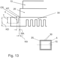
- the cooling structure 30 protrudes from the primary layer 10 and/or the secondary layer 20 in a direction running parallel to the main extension plane, ie in a direction running perpendicular to the projection direction.
- the cooling structure 30 preferably protrudes more than 1 mm from an edge KP, in particular the edge KP facing the cooling structure 30, of the primary layer 10 and/or the secondary layer 20.
- the recess 5 in the cooling structure 30 provided as an expansion joint preferably runs in the shape of a trench and, for example, is closed or continuous along a region of the edge KP of the primary layer 10 and/or the secondary layer 20, in particular within the main extension plane.
- the recess 5 extending along the edge KP is provided with interruptions.
- the recess 5 extends essentially parallel to the edge KP.
- the recess 5 is preferably curved, in particular in an area opposite the open side OS.
- a ratio of the depth T of the recess 5 to a cooling structure thickness KD assumes a value between 0.25 and 0.9, preferably between 0.3 and 0.8 and particularly preferably between 0.45 and 0.7.
- a ratio of the depth T of the recess 5 to a cooling structure thickness KD assumes a value between 0.25 and 0.9, preferably between 0.3 and 0.8 and particularly preferably between 0.45 and 0.7.
Landscapes
- Cooling Or The Like Of Semiconductors Or Solid State Devices (AREA)
- Structure Of Printed Boards (AREA)
Description
Die vorliegende Erfindung betrifft ein Trägersubstrat für elektrische, insbesondere elektronische, Bauteile und ein Verfahren zur Herstellung eines Trägersubstrats.The present invention relates to a carrier substrate for electrical, in particular electronic, components and a method for producing a carrier substrate.
Trägersubstrate sind beispielsweise als Leiterplatten oder Platinen bekannt. Typischerweise werden auf einer Bauteilseite des Trägersubstrats elektrische bzw. elektronische Bauteile und Leiterbahnen angeordnet, wobei die elektrischen bzw. elektronischen Bauteile und die Leiterbahnen zu elektrischen Schaltkreisen zusammenschaltbar sind. Für Spezialanwendungen haben sich solche Trägersubstrate als besonders vorteilhaft erwiesen, die zur elektrischen Isolation der einzelnen elektrischen Bauteile und Leiterbahnen eine Isolationsschicht mit hoher elektrischer Isolationsfestigkeit aufweisen, wie z.B. eine aus Keramik gefertigte Primärschicht.Carrier substrates are known, for example, as printed circuit boards or circuit boards. Electrical or electronic components and conductor tracks are typically arranged on one component side of the carrier substrate, whereby the electrical or electronic components and the conductor tracks can be connected together to form electrical circuits. For special applications, carrier substrates that have an insulating layer with high electrical insulation strength for the electrical insulation of the individual electrical components and conductor tracks, such as a primary layer made of ceramic, have proven to be particularly advantageous.
Im Betrieb dieser Trägersubstrate, insbesondere bei Einsätzen in der Leistungselektronik, werden die elektrischen Bauteile typischerweise derart beansprucht, dass sie erhitzen und sich auf der Bauteilseite lokale Wärmequellen ausbilden. Um durch das Erhitzen veranlasste Schädigungen an den elektrischen Bauteilen oder dem Trägersubstrat zu vermeiden, kennt der Stand der Technik daher Wärmesenken oder Kühlstrukturen, die in der Regel an einer der Bauteilseite gegenüberliegenden Kühlseite, die beispielsweise als an die Primärschicht angrenzende Kupferschicht bzw. Kupferbasis ausgebildet ist, angebracht, z.B. angelötet sind. Dabei kann das thermomechanische Verhalten des Trägersubstrats im Betrieb in nachteilhafter Weise zu mechanischen Spannungen im Trägersubstrat führen. Bisherige Lösungen, die das thermomechanisches Verhalten des Trägersubstrats insbesondere am Randbereich beeinflussen, wie beispielsweise in der
Die
Aus der
Die
Es ist somit eine Aufgabe der vorliegenden Erfindung, ein Trägersubstrat bereitzustellen, mit dem mechanischen Spannungen entgegengewirkt werden kann, ohne den Nutzungsspielraum auf der Bauteilseite des Trägersubstrats einzuschränken.It is therefore an object of the present invention to provide a carrier substrate with which mechanical stresses can be counteracted without restricting the scope of use on the component side of the carrier substrate.
Diese Aufgabe wird gelöst durch ein Trägersubstrat für elektrische Bauteile gemäß Anspruch 1 und ein Verfahren gemäß Anspruch 10. Weitere Vorteile und Merkmale der Erfindung ergeben sich aus den Unteransprüchen sowie der Beschreibung und den beigefügten Figuren.This object is achieved by a carrier substrate for electrical components according to
Erfindungsgemäß ist ein Trägersubstrat für elektrische Bauteile, insbesondere elektronische Bauteile, vorgesehen, wobei das Trägersubstrat eine aus Keramik gefertigte Primärschicht und mindestens eine an die Primärschicht angebundene Metallschicht aufweist, wobei die mindestens eine Metallschicht auf der der Primärschicht zugewandten Seite mindestens eine, bevorzugt mehrere Ausnehmungen aufweist.According to the invention, a carrier substrate for electrical components, in particular electronic components, is provided, wherein the carrier substrate has a primary layer made of ceramic and at least one metal layer bonded to the primary layer, wherein the at least one metal layer has at least one, preferably several, recesses on the side facing the primary layer.
Gegenüber den Trägersubstraten aus dem Stand der Technik hat die erfindungsgemäße Metallschicht den Vorteil, dass die das thermische bzw. das thermomechanische Verhalten beeinflussenden Ausnehmungen auf der der Primärschicht zugewandten Seite, insbesondere unmittelbar an die Primärschicht angrenzend, angeordnet sind. Dadurch wird beispielsweise die Oberfläche, die auf der Bauteilseite zur Anbindung von elektrischen bzw. elektronischen Bauteilen vorgesehen ist, nicht beeinträchtigt bzw. eingeschränkt, sondern steht dem Nutzer vollumfänglich zum Anbringen von elektronischen Bauteilen, Drahtbonds und/oder Terminals für eine Zu- und Ableitung verschiedener elektrischer Ströme und Spannungen zur Verfügung. Gleichzeitig wirken sich die Ausnehmungen positiv auf das Trägersubstrat aus, indem sie abhängig von ihrer Lokalisierung eine Temperaturwechselbeständigkeit des Trägersubstrats bis um das 10-fache steigern oder mechanische Spannungen verteilen, so dass z.B. lokalen mechanischen Spannungsspitzen im Randbereich des Trägersubstrats, insbesondere solche aus der Primärschicht stammende, entgegengewirkt werden kann. Diese Ausnehmungen können ferner in Hinblick auf ihr Volumen vergleichsweise klein gestaltet werden. Dies erlaubt die Anordnung der Ausnehmungen unmittelbar in demjenigen Bereich, in dem die Primärschicht an die Metallschicht angrenzt und in dem die größten thermomechanisch induzierten Spannungen entstehen. Außerdem kann im Herstellungsprozess darauf verzichtet werden, die Ausnehmung von der Bauteilseite ausgehend bis zur Primärschicht in die Metallschicht einzubringen. In einer Ausführungsform umfasst das Trägersubstrat nur die Primärschicht und die mindestens eine Metallschicht, d. h. das Trägersubstrat ist zweilagig ausgestaltet.Compared to the carrier substrates from the prior art, the metal layer according to the invention has the advantage that the recesses influencing the thermal or thermomechanical behavior are arranged on the side facing the primary layer, in particular directly adjacent to the primary layer. As a result, for example, the surface provided on the component side for connecting electrical or electronic components is not impaired or restricted, but is fully available to the user for attaching electronic components, wire bonds and/or terminals for supplying and discharging various electrical currents and voltages. At the same time, the recesses have a positive effect on the carrier substrate by increasing the carrier substrate's resistance to thermal shock by up to 10 times, depending on their location, or by distributing mechanical stresses, so that, for example, local mechanical stress peaks in the edge area of the carrier substrate, in particular those originating from the primary layer, can be counteracted. These recesses can also be designed to be comparatively small in terms of their volume. This allows the arrangement of the recesses directly in the area in which the primary layer adjoins the metal layer and in which the greatest thermomechanically induced stresses arise. In addition, the manufacturing process can dispense with the introduction of the recess into the metal layer from the component side to the primary layer. In one embodiment, the carrier substrate only has the primary layer and at least one metal layer, ie the carrier substrate is designed in two layers.
Weiterhin bieten die der Primärschicht zugewandten Ausnehmungen größere Freiheitsgrade hinsichtlich ihres Design, d. h. Form und Anordnung, und der Anzahl der eingebrachten Ausnehmungen, da sie unabhängig von der Bauteilseite bzw. Oberfläche sind, insbesondere unabhängig von Vorgaben durch die Bauteilseite. Beispielsweise können mehrere Reihen der Ausnehmungen ausgehend vom Randlauf der Metallschicht in deren Zentralbereich verlaufen. Die Ausnehmungen können sich dabei sowohl über die gesamte Dicke der Metallschicht erstrecken, also durchgängig sein oder dort nur teilweise eingeätzt sein, so dass die Metallschicht an bestimmten Stellen, bevorzugt am Rand, lokal lediglich geschwächt ist. Dadurch wird in vorteilhafter Weise die Fläche spannungsreduzierender Ausnehmungen vergrößert, was es wiederum ermöglicht gegebenenfalls auftretende thermomechanische Spannungen auf eine größere Fläche zu verteilen. Dies vermindert schließlich die Gefahr einer rissauslösenden lokalen Spannungsüberhöhung erheblich. Nach einer Ausführungsform der Erfindung ist die Metallschicht eine strukturierte Metallfläche, wie z. B. eine Leiterbahn, an der zur Bildung eines Schaltkreises elektrische bzw. elektronische Bauteile montierbar sind.Furthermore, the recesses facing the primary layer offer greater degrees of freedom in terms of their design, i.e. shape and arrangement, and the number of recesses introduced, since they are independent of the component side or surface, in particular independent of specifications by the component side. For example, several rows of recesses can run from the edge of the metal layer into its central area. The recesses can extend over the entire thickness of the metal layer, i.e. be continuous, or only partially etched there, so that the metal layer is only locally weakened at certain points, preferably at the edge. This advantageously increases the area of stress-reducing recesses, which in turn makes it possible to distribute any thermomechanical stresses that may occur over a larger area. This ultimately significantly reduces the risk of a local stress increase that triggers cracks. According to one embodiment of the invention, the metal layer is a structured metal surface, such as a conductor track, on which electrical or electronic components can be mounted to form a circuit.
Weiterhin ist es besonderes bevorzugt vorgesehen, dass die Ausnehmungen in die Metallschicht eingeätzt sind. Hierzu werden die Ausnehmungen im Besonderen zeitlich vor dem Fügen der Metallschicht mit der Primärschicht in die Metallschicht eingeätzt und anschließend wird die Metallschicht beim Fügen derart ausgerichtet, dass die Ausnehmungen an der Primärseite anliegen bzw. an der Primärschicht angrenzen. Beispielsweise ist die Primärschicht aus Al2O3, Si3N4, AIN oder einer HPSX-Keramik (, d. h. einer Keramik mit einer Al2O3- Matrix, die einen x-prozentigen Anteil an ZrO2 umfasst, beispielsweise Al2O3 mit 9% ZrO2 = HPS9 oder Al2O3 mit 25% ZrO2 = HPS25) gefertigt.Furthermore, it is particularly preferred that the recesses are etched into the metal layer. For this purpose, the recesses are etched into the metal layer in particular before the metal layer is joined to the primary layer and then the metal layer is aligned during joining in such a way that the recesses lie on the primary side or border on the primary layer. For example, the primary layer is made of Al 2 O 3 , Si 3 N 4 , AIN or an HPSX ceramic (i.e. a ceramic with an Al 2 O 3 matrix that contains an x percent ZrO 2 , for example Al 2 O 3 with 9% ZrO 2 = HPS9 or Al 2 O 3 with 25% ZrO 2 = HPS25).
In einer weiteren Ausführungsform der vorliegenden Erfindung werden die Ausnehmungen mit einem Füllmaterial befüllt, wobei das Füllmaterial in seinem bestimmungsgemäßen Zustand insbesondere einen niedrigeren Ausdehnungskoeffizient und/oder ein höheres E-Modul als ein Material, aus dem die Metallschicht gefertigt ist, aufweist. Beispielsweise hat das Füllmaterial einen Längenausdehnungskoeffizienten kleiner als Kupfer, d.h. α < 16,5 x 10⁻⁶ K-1, gemessen bei Raumtemperatur. Das Füllmaterial kann dabei in vorteilhafter Weise dazu genutzt werden, einen nachfolgenden Fügeprozess, bei dem das Trägersubstrat in seinen bestimmungsgemäßen Zustand gebracht wird, durch eine stoffschlüssige Verbindung zwischen dem Füllmaterial und der Metallschicht einerseits und zwischen dem Füllmaterial und der Primärschicht anderseits zu unterstützen bzw. zu ermöglichen. Ferner ist es vorstellbar, dass das Füllmaterial derart gewählt ist, dass sich im Bereich des Randverlaufs lokal ein niedrigerer kombinierter Ausdehnungskoeffizient (CTE) einstellt, der die fügetemperaturbedingten thermomechanischen Spannungen beim Abkühlen nach dem Fügeprozess von der Grenzfläche der Primärschicht zur Metallschicht teilweise in die Metallschicht verlagert, in der die thermomechanischen Spannung wiederum während der Abkühlung besser abgebaut werden können. Als Füllmaterialien sind beispielsweise partikelgefüllte Weichlot-, Hartlot- oder Aktivlote vorstellbar, die einen Gehalt von 10 - 64 Vol.-%, vorzugsweise 20 - 50 Vol.-% und besonders bevorzugt 30 - 50 Vol.-% an Keramiken- oder Metallpartikeln mit den oben beschriebenen Eigenschaften enthalten wie z.B. SiC, AIN, Al2O3, HPSX, BeO, Si3N4, ZnO, TiN, B4C, Mo, W, Cr, Ta oder Nb.In a further embodiment of the present invention, the recesses are filled with a filling material, wherein the filling material in its intended state has in particular a lower coefficient of expansion and/or a higher modulus of elasticity than a material from which the metal layer is made. For example, the filling material has a coefficient of linear expansion smaller than copper, i.e. α < 16.5 x 10 -6 K -1 , measured at room temperature. The filling material can advantageously be used to support or enable a subsequent joining process in which the carrier substrate is brought into its intended state by means of a material-to-material connection between the filling material and the metal layer on the one hand and between the filling material and the primary layer on the other. Furthermore, it is conceivable that the filler material is selected in such a way that a lower combined coefficient of expansion (CTE) is established locally in the area of the edge profile, which partially shifts the thermomechanical stresses caused by the joining temperature during cooling after the joining process from the interface between the primary layer and the metal layer into the metal layer, in which the thermomechanical stresses can in turn be better reduced during cooling. Possible filler materials include, for example, particle-filled soft solder, hard solder or active solder which contain 10 - 64 vol.%, preferably 20 - 50 vol.% and particularly preferably 30 - 50 vol.% of ceramic or metal particles with the properties described above, such as SiC, AIN, Al 2 O 3 , HPSX, BeO, Si 3 N 4 , ZnO, TiN, B 4 C, Mo, W, Cr, Ta or Nb.
Die Primärschicht weist insbesondere eine Isolationsschicht mit hoher elektrischer Isolationsfestigkeit auf, bevorzugt von mehr als 5 kV/mm, besonders bevorzugt von
mehr als 10, 20 oder sogar mehr als 30 kV/mm und/oder mit hoher Wärmeleitfähigkeit auf, bevorzugt von mehr als 10 W/mK, besonders bevorzugt von mehr als 20 oder sogar mehr als 60 W/mK, wie z.B. technische Keramiken oder mit wärmeleitenden Materialen gefüllte organische Isolationswerkstoffe.The primary layer has in particular an insulation layer with high electrical insulation strength, preferably of more than 5 kV/mm, particularly preferably of
more than 10, 20 or even more than 30 kV/mm and/or with high thermal conductivity, preferably more than 10 W/mK, particularly preferably more than 20 or even more than 60 W/mK, such as technical ceramics or organic insulation materials filled with thermally conductive materials.
Vorzugsweise ist es vorgesehen, dass die der Bauteilseite zugewandte Seite der Metallschicht, insbesondere die strukturierte Metallfläche, zumindest bereichsweise eine glatte, d. h. eine ausnehmungsfreie, Oberfläche aufweist. Nach einer Ausführungsform der Erfindung sind die Ausnehmungen derart ausgestaltet, dass eine geschlossene Oberflächenseite der strukturierten Metallfläche, die der Bauteilseite zugewandt ist, größer ist als die Kontaktflächen, über die die strukturierte Metallfläche mit der Primärschicht in Kontakt steht bzw. angebunden ist. Vorstellbar ist auch, dass die Ausnehmungen lochartig und/oder sacklochartig ausgestaltet sind, d. h. die Ausnehmungen greifen durch die Metallschicht durch oder münden bzw. enden, bevorzugt dom- oder kuppelförmig, im Inneren der Metallschicht. Denkbar ist auch eine Ausführungsform, in der lochartige Ausnehmungen und sacklochartige Bohrungen in der Metallschicht realisiert sind, wobei die Anzahl der lochartigen Ausnehmungen kleiner ist als die Anzahl der sacklochartigen Ausnehmungen. Weiterhin ist es bevorzugt vorgesehen, dass in einer senkrecht zur Haupterstreckungsebene des Trägersubstrats verlaufenden Projektionsrichtung bzw. -orientierung unterhalb eines für das Bauteil vorgesehenen Stellplatz bzw. Anbindungsplatz keine oder im Vergleich zur übrigen Metallschicht weniger Ausnehmungen angeordnet sind.It is preferably provided that the side of the metal layer facing the component side, in particular the structured metal surface, has a smooth, i.e. recess-free, surface at least in some areas. According to one embodiment of the invention, the recesses are designed such that a closed surface side of the structured metal surface facing the component side is larger than the contact surfaces via which the structured metal surface is in contact with or connected to the primary layer. It is also conceivable that the recesses are designed as hole-like and/or blind-hole-like, i.e. the recesses penetrate through the metal layer or open or end, preferably in the shape of a dome or cupola, in the interior of the metal layer. An embodiment is also conceivable in which hole-like recesses and blind-hole-like bores are realized in the metal layer, wherein the number of hole-like recesses is smaller than the number of blind-hole-like recesses. Furthermore, it is preferably provided that in a projection direction or orientation running perpendicular to the main extension plane of the carrier substrate, no recesses or fewer recesses are arranged below a location or connection location provided for the component compared to the rest of the metal layer.
Weitere Vorteile und Merkmale ergeben sich aus der nachfolgenden Beschreibung bevorzugter Ausführungsformen des erfindungsgemäßen Gegenstands. Einzelne Merkmale der einzelnen Ausführungsformen können dabei im Rahmen der Erfindung miteinander kombiniert werden.Further advantages and features emerge from the following description of preferred embodiments of the subject matter according to the invention. Individual features of the individual embodiments can be combined with one another within the scope of the invention.
Gemäß einer weiteren Ausführungsform der vorliegenden Erfindung ist vorgesehen, dass die Ausnehmung am Randverlauf der Metallschicht angeordnet ist. Der Randverlauf der Metallschicht ist vorzugsweise durch eine Linie festgelegt, entlang der die Metallschicht ihren direkten Kontakt zur Primärschicht beendet. Insbesondere wird der Randverlauf, d.h. die Randlinie, bzw. dessen Oberfläche durch die Ausnehmungen vergrößert, wodurch im Betrieb auftretende mechanische Spannungen, insbesondere solche, die von der Primärschicht herrühren, besser verteilt werden können. Unter Randverlauf ist im Besonderen ein äußerer Umfang der Randschicht in einer parallel zur Haupterstreckungsebene des Trägersubstrats verlaufenden Ebene zu verstehen. In einer Ausführungsform ist die Ausnehmung in einer an der Primärschicht anliegenden Kante der Metallschicht eingelassen. Hierbei verursacht die Ausnehmung im Randverlauf einen maximal um eine Einrücktiefe rückspringenden Konturverlauf. Die durchschnittliche Einrücktiefe, d. h. die über die Ausnehmungen im Randverlauf gemittelten Einrücktiefe, nimmt hierbei einen Wert zwischen 50 µm und 1000 µm ein, bevorzugt zwischen 100 µm und 800 µm und besonders bevorzugt zwischen 150 µm und 600 µm.According to a further embodiment of the present invention, it is provided that the recess is arranged on the edge profile of the metal layer. The edge profile of the metal layer is preferably defined by a line along which the metal layer ends its direct contact with the primary layer. In particular, the edge profile, ie the edge line, or its surface is enlarged by the recesses, whereby mechanical stresses occurring during operation, in particular those originating from the primary layer, can be better distributed. The edge profile is in particular an outer circumference the edge layer in a plane running parallel to the main extension plane of the carrier substrate. In one embodiment, the recess is let into an edge of the metal layer adjacent to the primary layer. The recess in the edge profile causes a contour that is set back by a maximum of one indentation depth. The average indentation depth, ie the indentation depth averaged over the recesses in the edge profile, takes on a value between 50 µm and 1000 µm, preferably between 100 µm and 800 µm and particularly preferably between 150 µm and 600 µm.
Weiterhin ist es beispielsweise vorgesehen, dass für die Ausnehmungen im Randverlauf vorgesehen ist, dass ein Verhältnis einer in Projektionsrichtung bemessenen Tiefe der Ausnehmung zur Einrücktiefe einen Wert zwischen 0,2 und 1,2 annimmt, bevorzugt zwischen 0,3 und 1,0 und besonders bevorzugt zwischen 0,4 und 0,8 annimmt. Gemäß einer weiteren bevorzugten Ausführungsform der vorliegenden Erfindung ist vorgesehen, dass zwischen 10 % und 80 %, bevorzugt zwischen 30% und 80% und besonders bevorzugt zwischen 50 % und 75 % eines den Ausnehmungen zugeordneten Volumens in einem Randbereich angeordnet ist, wobei der Randbereich bevorzugt unabhängig von der Größe des Trägersubstrats gleich groß ist. Der Randbereich ist der Bereich, in dem 60 % - 100 %, bevorzugt 80% - 100% aller Ausnehmungen angeordnet sind.Furthermore, it is provided, for example, that for the recesses in the edge profile, a ratio of a depth of the recess measured in the projection direction to the indentation depth assumes a value between 0.2 and 1.2, preferably between 0.3 and 1.0 and particularly preferably between 0.4 and 0.8. According to a further preferred embodiment of the present invention, it is provided that between 10% and 80%, preferably between 30% and 80% and particularly preferably between 50% and 75% of a volume assigned to the recesses is arranged in an edge region, wherein the edge region is preferably the same size regardless of the size of the carrier substrate. The edge region is the region in which 60% - 100%, preferably 80% - 100% of all recesses are arranged.
Vorteilhafterweise bilden mehrere Ausnehmungen, insbesondere mehrere nebeneinander angeordnete Ausnehmungen, einen mäanderförmigen, briefmarkenrandförmigen und/oder einen sägezahnförmigen Randverlauf der Metallschicht aus, wobei sich insbesondere der mäanderförmige, briefmarkenrandförmige und/oder der sägezahnförmige Randverlauf über den gesamten Randverlauf der Metallschicht erstreckt. Vorstellbar ist auch, dass sich der mäanderförmige, briefmarkenrandförmige und/oder sägezahnförmige Randverlauf der Metallschicht nur über einen Teilbereich des gesamten Randverlaufs der Metallschicht erstreckt bzw. mehrere Teilbereich in Umlaufrichtung gesehen zueinander beabstandet aneinander anschließen.Advantageously, several recesses, in particular several recesses arranged next to one another, form a meandering, postage stamp-shaped and/or sawtooth-shaped edge profile of the metal layer, wherein in particular the meandering, postage stamp-shaped and/or sawtooth-shaped edge profile extends over the entire edge profile of the metal layer. It is also conceivable that the meandering, postage stamp-shaped and/or sawtooth-shaped edge profile of the metal layer extends only over a partial area of the entire edge profile of the metal layer or that several partial areas adjoin one another at a distance from one another as seen in the circumferential direction.
Durch die Ausbildung eines strukturierten Randverlaufs wird dessen Oberflächenvergrößerung so ausgelegt, dass im Wesentlichen unabhängig vom Ort des Auftretens einer mechanischen Spannung diese vorteilhaft verteilt werden kann. Der Randverlauf kann aber auch unregelmäßige Ausnehmungen aufweisen, d.h. z.B. kleine und größere Ausnehmungen, die gemischt oder abwechselnd zueinander angeordnet sind, oder die wellenlienienförmig, rechteckförmig, parallelogrammförmig oder zackig ausgebildet sind. Grundsätzlich ist es bevorzugt vorgesehen, dass sich an den Randverlauf ein geschlossener Streifen der Metallschicht ausbildet, wobei der Streifen insbesondere zu einen Seite hin den mäanderförmigen, briefmarkenrandförmigen und/oder sägezahnförmigen Randverlauf aufweist. Weiterhin ist es vorstellbar, dass innerhalb der Ausnehmungen im Randverlauf zusätzliche Nadel-, Dom- oder Stiftstrukturen angeordnet sind, die die Primärschicht mit der Metallschicht verbinden, um dadurch die mechanische Spannungsverteilung zu homogenisieren bzw. auf eine größere Fläche zu verteilen.By forming a structured edge profile, its surface area is enlarged in such a way that mechanical stress can be advantageously distributed essentially regardless of the location where it occurs. The edge profile can also have irregular recesses, i.e., for example, small and large recesses that are mixed or arranged alternately with one another, or that are wavy, rectangular, parallelogram-shaped or jagged. In principle, it is preferably provided that a closed strip of the metal layer is formed along the edge profile, with the strip having the meandering, postage stamp-shaped and/or sawtooth-shaped edge profile, particularly towards one side. It is also conceivable that additional needle, dome or pin structures are arranged within the recesses in the edge profile, which connect the primary layer to the metal layer in order to homogenize the mechanical stress distribution or to distribute it over a larger area.
Zweckmäßig ist es vorgesehen, dass die Ausnehmung als Wölbung, insbesondere als kuppelartige oder teilkuppelartige Wölbung, ausgestaltet ist. Die Wölbung ist dabei zu der der Primärschicht abgewandten Seite der angebundenen Metallschicht hin gerichtet. Dadurch wird in vorteilhafter Weise vermieden, dass die Ausnehmungen auf der Primärschicht abgewandten Seite der Metallschicht in Erscheinung treten. So kann die von der Primärschicht abgewandte Seite der Metallschicht vollständig für Bauteile genutzt werden. Insbesondere bilden die Ausnehmungen im Zentralbereich der Metallschicht Hohlräume zwischen der Metallschicht und der Primärschicht aus. Im Randverlauf bildet die Metallschicht beispielsweise in einer senkrecht zur Haupterstreckungsebene verlaufenden Richtung ein Überhang aus. Weiterhin ist es vorstellbar, dass die Ausnehmung in einem Querschnitt, insbesondere in einer parallel zur Haupterstreckungsebene verlaufenden Ebene, oval, karoförmig, rautenförmig oder rillenförmig ausgestaltet ist.It is expedient for the recess to be designed as a curvature, in particular as a dome-like or partially dome-like curvature. The curvature is directed towards the side of the attached metal layer facing away from the primary layer. This advantageously prevents the recesses from appearing on the side of the metal layer facing away from the primary layer. The side of the metal layer facing away from the primary layer can thus be used entirely for components. In particular, the recesses in the central region of the metal layer form cavities between the metal layer and the primary layer. In the edge course, the metal layer forms an overhang, for example in a direction running perpendicular to the main extension plane. It is also conceivable for the recess to be designed to be oval, diamond-shaped, diamond-shaped or groove-shaped in a cross-section, in particular in a plane running parallel to the main extension plane.
Gemäß einer weiteren Ausführungsform der vorliegenden Erfindung ist vorgesehen, dass die Ausnehmung in einer senkrecht zur Haupterstreckungsebene verlaufenden Richtung eine durchschnittliche Tiefe aufweist, die im Verhältnis zur kleinsten Öffnungsweite der Ausnehmung, beispielsweise einem Durchmesser bei einer kreisförmigen Ausnehmung oder einer Breite einer grabenförmigen Ausnehmung, vorzugsweise einen Wert zwischen 0,2 und 1,2, bevorzugt zwischen 0,3 und 1,0 und besonders bevorzugt von 0,4 bis 0,8 annimmt. Besonders bevorzugt ist es vorgesehen, dass die Ausnehmungen in Hinblick auf das thermische Verhalten des Trägersubstrats möglichst klein sind. Vorstellbar ist auch, dass sich die Ausnehmungen über die gesamte Metallschicht verteilen. Hierbei ist es vorstellbar, dass sich die Tiefen über die gesamte Metallschicht statistische oder willkürlich verteilen. Es ist auch vorstellbar, dass gleichartige Ausnehmungen mit dem kürzeren Abstand zum Randverlauf im Mittel tiefer sind als die Ausnehmungen zum Zentralbereich hin gesehen, beispielsweise um einen Faktor zwischen 1,01 und 3,0, bevorzugt um einen Faktor zwischen 1,1 und 2,5 und besonders bevorzugt um einen Faktor zwischen 1,3 und 2,0. Erfindungsgemäß ist es vorgesehen, dass die Metallschicht im Zentralbereich einen ersten Teilbereich und einen zweiten Teilbereich aufweist, wobei sich die Anzahl der Ausnehmungen und/oder die Tiefe bzw. Größe im ersten Teilbereich von der Anzahl der Ausnehmungen und/oder deren Tiefe bzw Größe im zweiten Teilbereich unterscheidet. Hierbei werden der erste Teilbereich und der zweite Teilbereich abhängig von Trägersubstrat bzw. dessen Einsatzfeld ausgestaltet.According to a further embodiment of the present invention, it is provided that the recess has an average depth in a direction perpendicular to the main extension plane, which in relation to the smallest opening width of the recess, for example a diameter for a circular recess or a width of a trench-shaped recess, preferably assumes a value between 0.2 and 1.2, preferably between 0.3 and 1.0 and particularly preferably from 0.4 to 0.8. It is particularly preferred that the recesses are as small as possible with regard to the thermal behavior of the carrier substrate. It is also conceivable that the recesses are distributed over the entire metal layer. In this case, it is conceivable that the depths are distributed statistically or arbitrarily over the entire metal layer. It is also conceivable that similar recesses with the shorter distance to the edge are on average deeper than the recesses towards the central region, for example by a factor of between 1.01 and 3.0, preferably by a factor of between 1.1 and 2.5 and particularly preferably by a factor of between 1.3 and 2.0. According to the invention, the metal layer in the central region has a first partial region and a second partial region, wherein the number of recesses and/or the depth or size in the first partial region differs from the number of recesses and/or their depth or size in the second partial region. The first partial region and the second partial region are designed depending on the carrier substrate or its field of application.
Erfindungsgemäß es vorgesehen, dass sich die durchschnittliche Anzahl und/oder durchschnittliche Tiefe der Ausnehmungen (bezogen auf Flächenabschnitte bzw. pro Teilbereich der Metallschicht) über die Metallschicht gesehen kontinuierlich ändert. Beispielsweise nimmt die Anzahl und/oder Tiefe der Ausnehmung in Richtung Randverlauf des Metallschicht zu oder ab. Weiterhin ist es vorstellbar, dass das Verhältnis zwischen der Tiefe der Ausnehmungen zur Dicke der strukturierten Metallfläche zwischen 2,5 % und 70 %, bevorzugt zwischen 5 % und 60 % und besonders bevorzugt zwischen 10 % und 55 % beträgt. In bestimmungsgemä-ßer Weise bezieht sich das Verhältnis der Tiefe der Ausnehmungen zur Dicke der Metallschicht auf Metallschichtdicken zwischen 200 µm und 2000 µm, bevorzugt zwischen 250 µm und 1500 µm und besonders bevorzugt zwischen 300 µm und 1000 µm.According to the invention, the average number and/or average depth of the recesses (based on surface sections or per partial area of the metal layer) changes continuously across the metal layer. For example, the number and/or depth of the recess increases or decreases in the direction of the edge of the metal layer. It is also conceivable that the ratio between the depth of the recesses and the thickness of the structured metal surface is between 2.5% and 70%, preferably between 5% and 60% and particularly preferably between 10% and 55%. In accordance with the specification, the ratio of the depth of the recesses to the thickness of the metal layer refers to metal layer thicknesses between 200 µm and 2000 µm, preferably between 250 µm and 1500 µm and particularly preferably between 300 µm and 1000 µm.
In einer weiteren besonders bevorzugten Ausführungsform ist eine Erstausnehmung als durchgängige grabenförmige Vertiefung vorgesehen, die parallel zum Randverlauf der Metallschicht verläuft und kuppelartig in der Metallschicht endet. Unter Erstausnehmung versteht der Fachmann insbesondere die vom Randverlauf gesehen ersten in die Metallschicht eingelassenen und vom Randverlauf beabstandeten Ausnehmungen bzw. eine erste Gruppe von solchen Ausnehmungen. Es können dabei eine oder mehrere durchgängige Erstausnehmungen nebeneinander parallel zum Randverlauf der Metallschicht in die Metallschicht eingebracht werden. Dabei weist die grabenförmige Vertiefung in der Metallschicht einen ersten Abstand vom Randverlauf der Metallschicht von 100 µm bis 1000 µm, bevorzugt 110 µm bis 600 µm und besonders bevorzugt von 150 µm bis 400 µm auf. Alle weiteren Ausnehmungen, die parallel zur durchgängigen gabenförmigen Vertiefung verlaufen, können durchgängig oder als mehrere nebeneinanderliegende diskrete Ausnehmungen gestaltet werden. Ein zweiter Abstand aller weiteren Ausnehmungen zur Ausnehmung weist Werte zwischen 100 µm und 1000 µm, bevorzugt 110 µm und 600 µm und besonders bevorzugt von 150 µm und 400 µm auf. Die Tiefe der Ausnehmungen und die Tiefe der weiteren Ausnehmung ist dabei kleiner als die Dicke der Metallschicht und weisen vorzugsweise Werte zwischen 2,5 % und 70 %, bevorzugt zwischen 5 % und 60 % und besonders bevorzugt zwischen 10 % und 55 % der Metallschichtdicke auf.In another particularly preferred embodiment, a first recess is provided as a continuous trench-shaped depression that runs parallel to the edge of the metal layer and ends in the metal layer like a dome. The person skilled in the art understands the term first recess to mean in particular the first recesses let into the metal layer from the edge and spaced apart from the edge, or a first group of such recesses. One or more continuous first recesses can be made next to one another in the metal layer parallel to the edge of the metal layer. The trench-shaped depression in the metal layer has a first distance from the edge of the metal layer of 100 µm to 1000 µm, preferably 110 µm to 600 µm and particularly preferably 150 µm to 400 µm. All other recesses that run parallel to the continuous, dome-shaped depression can be designed to be continuous or as several discrete recesses lying next to one another. A second distance of all further recesses from the recess has values between 100 µm and 1000 µm, preferably 110 µm and 600 µm and particularly preferably 150 µm and 400 µm. The depth of the recesses and the depth of the further recess is smaller than the thickness of the metal layer and preferably have values between 2.5% and 70%, preferably between 5% and 60% and particularly preferably between 10% and 55% of the metal layer thickness.
Gemäß einer weiteren bevorzugten Ausführungsform sind diskrete Erstausnehmungen vorgesehen, die in Reihe parallel zum Randverlauf der Metallschicht angeordnet sind. Die Erstausnehmungen weisen einen ersten Abstand vom Randverlauf der Metallschicht von 100 µm bis 1000 µm, bevorzugt 110 µm bis 600 µm und besonders bevorzugt von 150 µm bis 400 µm auf. Des Weiteren ist es vorzugsweise vorgesehen, dass sich an diese Reihe mit Erstausnehmungen eine Reihe mit weiteren Ausnehmungen oder sogar mehrere Reihen mit diskreten oder auch in Richtung der Haupterstreckungsebene durchgängigen weiteren Ausnehmungen anschließen. Der Abstand der Erstausnehmungen zur weiteren Ausnehmung ist vorzugsweise 50 µm bis 1000 µm, in bevorzugter Weise 80 µm bis 600 µm und in besonders bevorzugter Weise 100 µm bis 400 µm. Weiterhin ist es vorzugsweise vorgesehen, dass Mittelpunkte der Erstausnehmung und der weiteren Ausnehmungen, bezogen auf die Haupterstreckungsebene der Metallschicht, entlang einer Linie, die sich senkrecht zum Randverlauf der Metallschicht oder unter Bildung eines Winkels zum Randverlauf der Metallschicht, der kleiner ist als 90° , angeordnet sind. Die Tiefe T der Erstausnehmungen und der weiteren Ausnehmungen ist dabei kleiner als die Dicke der Metallschicht und sie weisen Werte von 2,5% und 70%, bevorzugt zwischen 5% und 60% und besonders bevorzugt zwischen 10% und 55% beträgt der Metallschichtdicke auf.According to a further preferred embodiment, discrete initial recesses are provided which are arranged in a row parallel to the edge profile of the metal layer. The initial recesses have a first distance from the edge profile of the metal layer of 100 µm to 1000 µm, preferably 110 µm to 600 µm and particularly preferably 150 µm to 400 µm. Furthermore, it is preferably provided that this row of initial recesses is followed by a row of further recesses or even several rows of discrete further recesses or further recesses which are continuous in the direction of the main extension plane. The distance between the initial recesses and the further recess is preferably 50 µm to 1000 µm, preferably 80 µm to 600 µm and particularly preferably 100 µm to 400 µm. Furthermore, it is preferably provided that the center points of the first recess and the further recesses, based on the main extension plane of the metal layer, are arranged along a line that is perpendicular to the edge of the metal layer or forming an angle to the edge of the metal layer that is less than 90°. The depth T of the first recesses and the further recesses is smaller than the thickness of the metal layer and they have values of 2.5% and 70%, preferably between 5% and 60% and particularly preferably between 10% and 55% of the metal layer thickness.
Gemäß einer weiteren Ausführungsform sind Kanäle in der Metallschicht vorgesehen, wobei die Kanäle die Ausnehmungen mit einer das Trägersubstrat umgebenden Umgebung verbinden. Insbesondere werden die Kanäle zusammen, d. h. zeitglich, mit den Ausnehmungen in die Metallschicht eingeätzt und durch das Zusammenfügen der Metallschicht und der Primärschicht werden die Kanäle gebildet. Die Kanäle können in vorteilhafter Weise dazu benutzt werden, Ausnehmungen mit funktionellen Materialien, z.B. organischen Materialien, anorganischen Bindemitteln oder partikelgefüllten Materialien zu befüllen. Dies ist insbesondere deshalb positiv, da die Ausnehmungen vor dem Fügen nicht mit einem Füllmaterial befüllt werden können, weil diese nicht resistent sind gegenüber einer beim Fügen entstehenden Temperaturentwicklung. Das Befüllen mit dem Füllmaterial erweist sich zudem deshalb als vorteilhaft, als dass die Wahrscheinlichkeit für z. B. eine Teilententladung reduziert werden kann. Solche Teilentlandungen können andernfalls in luftgefüllten Bereichen zwischen der Metallschicht und der Primärschicht auftreten.According to a further embodiment, channels are provided in the metal layer, the channels connecting the recesses to an environment surrounding the carrier substrate. In particular, the channels are etched into the metal layer together, i.e. at the same time, with the recesses, and the channels are formed by joining the metal layer and the primary layer. The channels can advantageously be used to fill recesses with functional materials, e.g. organic materials, inorganic binders or particle-filled materials. This is particularly positive because the recesses cannot be filled with a filler material before joining because they are not resistant to the temperature development that occurs during joining. Filling with the filler material also proves to be advantageous because the probability of, for example, a partial discharge can be reduced. Such partial discharges can otherwise occur in air-filled areas between the metal layer and the primary layer.
Vorzugsweise ist es vorgesehen, dass die Metallschicht in Form einer Zwischenschicht zwischen der Primärschicht und einer Sekundärschicht angeordnet ist, wobei insbesondere die Zwischenschicht auf einer der Primärschicht zugewandten ersten Seite und/oder auf einer der Sekundärschicht zugewandten zweiten Seite eine oder mehrere Ausnehmungen aufweist. Die vorher beschriebenen Ausgestaltungen für die Ausnehmungen auf der der Primärschicht zugewandten Seite lassen sich analog auf die Ausnehmungen, die der Sekundärschicht zugewandt sind, übertragen. Vorstellbar ist, dass die Ausnehmung in der Zwischenschicht durchgreifend, beispielsweise als Loch oder Durchgangsbohrung, ausgestaltet ist, wobei sich die Ausnehmung von der Primärschicht bis zur Sekundärschicht erstreckt. Weiterhin ist es bevorzugt vorgesehen, dass die Zwischenschicht dicker ist als die Primär- und/oder Sekundärschicht. Insbesondere ist es vorgesehen, dass das Verhältnis zwischen Tiefe der Ausnehmung in der Zwischenschicht zur Dicke des Zwischenschicht kleiner ist als das Verhältnis zwischen Tiefe der Ausnehmung in der strukturierten Metallfläche zur Dicke der strukturierten Metallfläche. Vorzugsweise umfasst die Zwischenschicht zusätzlich zu den Ausnehmungen eine Hohlkammer innerhalb der Zwischenschicht.Preferably, it is provided that the metal layer is arranged in the form of an intermediate layer between the primary layer and a secondary layer, wherein in particular the intermediate layer has one or more recesses on a first side facing the primary layer and/or on a second side facing the secondary layer. The previously described embodiments for the recesses on the side facing the primary layer can be transferred analogously to the recesses facing the secondary layer. It is conceivable that the recess in the intermediate layer is designed to penetrate through, for example as a hole or through-bore, with the recess extending from the primary layer to the secondary layer. Furthermore, it is preferably provided that the intermediate layer is thicker than the primary and/or secondary layer. In particular, it is provided that the ratio between the depth of the recess in the intermediate layer to the thickness of the intermediate layer is smaller than the ratio between the depth of the recess in the structured metal surface to the thickness of the structured metal surface. In addition to the recesses, the intermediate layer preferably comprises a hollow chamber within the intermediate layer.
In einer weiteren Ausführungsform der vorliegenden Erfindung ist es vorgesehen, dass Ausnehmungen auf der zweiten Seite in einer senkrecht zur Haupterstreckungsebene verlaufenden Richtung im Wesentlichen deckungsgleich oder versetzt zu den Ausnehmungen auf der ersten Seite der Zwischenschicht angeordnet sind. Durch ein versetztes Anordnen der Ausnehmungen wird eine vergleichsweise widerstandfähige Metallschicht bereitgestellt, da auf eine lokale Schwächung der Metallschicht verzichtet wird. Weiterhin ist es von Vorteil, dass unterhalb von Bauteilen ein ausreichende Größe an Zwischenschicht bereitgestellt werden kann, über die im Betrieb die Wärme von den als Wärmequelle wirkenden Bauteilen wirkungsvoll zur Kühlseite abtransportiert werden kann. Insbesondere ist es vorgesehen, dass die Zwischenschicht in einem an den Randverlauf angrenzenden Bereich auf der ersten und der zweiten Seite einander gegenüberliegende Rillen, insbesondere eingeätzt Rillen, aufweist. Dadurch lässt sich ein in einer parallel zur Haupterstreckungsebene verlaufenden Richtung gesehen, zwischen einer der Rillen und dem äußersten Randverlauf angeordneter Bereich in vorteilhafter Weise als Kontaktelement in Form einer Verdickung bereitstellen. Vorzugsweise ragt diese Verdichtung gegenüber der Primärschicht und/oder der Sekundärschicht vor, um einen möglichst einfachen Zugriff auf das Kontaktelement der Zwischenschicht zu ermöglichen.In a further embodiment of the present invention, it is provided that recesses on the second side are arranged in a direction perpendicular to the main plane of extension, essentially congruent with or offset from the recesses on the first side of the intermediate layer. By arranging the recesses offset, a comparatively resistant metal layer is provided, since local weakening of the metal layer is avoided. It is also advantageous that a sufficiently large intermediate layer can be provided beneath components, via which the heat from the components acting as a heat source can be effectively transported to the cooling side during operation. In particular, it is provided that the intermediate layer has grooves, in particular etched grooves, lying opposite one another in an area adjacent to the edge profile on the first and second sides. As a result, an area arranged between one of the grooves and the outermost edge profile, viewed in a direction parallel to the main plane of extension, can advantageously be provided as a contact element in the form of a thickening. Preferably, this compaction protrudes from the primary layer and/or the secondary layer in order to enable the easiest possible access to the contact element of the intermediate layer.
In einer vorteilhaften Ausführungsform der vorliegenden Erfindung ist vorgesehen, dass die Metallschicht Teil einer Kühlstruktur ist, wobei die Kühlstruktur vorzugsweise an die Primärschicht oder Sekundärschicht angebunden ist, wobei insbesondere die Ausnehmung in der Metallschicht zur Bildung einer Dehnungsfuge in einem Bereich angrenzend an den Randverlauf der Primärschicht und/oder der Sekundärschicht ausgebildet ist. Insbesondere ist es vorgesehen, dass die als Dehnungsfuge dienende Ausnehmung nicht von der Primärschicht und/oder Sekundärschicht überdeckt ist. Dadurch ist es in vorteilhafter Weise möglich, dass eine thermische Längsausdehnung der Kühlstruktur nicht zur Ausbildung von mechanischen Spannungen führt, indem die als Dehnungsfuge dienende Ausnehmung die Längsausdehnung der Kühlstruktur auffängt.In an advantageous embodiment of the present invention, it is provided that the metal layer is part of a cooling structure, wherein the cooling structure is preferably connected to the primary layer or secondary layer, wherein in particular the recess in the metal layer is designed to form an expansion joint in an area adjacent to the edge of the primary layer and/or the secondary layer. In particular, it is provided that the recess serving as an expansion joint is not covered by the primary layer and/or secondary layer. This advantageously makes it possible for a thermal longitudinal expansion of the cooling structure not to lead to the formation of mechanical stresses, in that the recess serving as an expansion joint absorbs the longitudinal expansion of the cooling structure.
Insbesondere ist die Ausnehmung in solche Kühlstrukturen bzw. Teile von Kühlstrukturen eingelassen, die gegenüber der Primärschicht und/oder Sekundärschicht in einer parallel zur Haupterstreckungsebene verlaufenden Richtung überstehen. Dabei ist es vorstellbar, dass die Kühlstruktur einen Basiskörper und einen Stegbereich mit senkrecht zur Haupterstreckungsebene verlaufenden Stegen umfasst. Vorzugsweise umschließt bzw. umgibt die Ausnehmung umlaufend eine Kante der ersten Primärschicht und/oder der Sekundärschicht, insbesondere die Kante der Primärschicht und/oder der Sekundärschicht, die der Kühlstruktur zugewandt ist, d. h. die Ausnehmung bildet einen geschlossenen Graben bzw. eine geschlossen Sicke, die die Kante in der Haupterstreckungsebene umgibt.In particular, the recess is let into cooling structures or parts of cooling structures that protrude from the primary layer and/or secondary layer in a direction parallel to the main extension plane. It is conceivable that the cooling structure comprises a base body and a web region with webs running perpendicular to the main extension plane. The recess preferably encloses or surrounds an edge of the first primary layer and/or the secondary layer, in particular the edge of the primary layer and/or the secondary layer that faces the cooling structure, i.e. the recess forms a closed trench or a closed bead that surrounds the edge in the main extension plane.
Zweckmäßig ist es vorgesehen, dass eine zur Primärschicht und/oder Sekundärschicht offene Seite der Aussparung zumindest teilweise von der Primärschicht und/oder der Sekundärschicht bedeckt ist. Mit anderen Worten, die Ausnehmung kann zumindest teilweise in Projektionsrichtung gesehen unterhalb der Primärschicht und/oder der Sekundärschicht angeordnet sein. Es ist auch vorstellbar, dass die Kante der Primärschicht und/oder der Sekundärschicht bündig an einen Rand, insbesondere den innenliegenden Rand, der Ausnehmung anschließt. Vorzugsweise nimmt ein Verhältnis zwischen einem bedeckten Bereich der offenen Seite zur Breite der Ausnehmung einen Wert zwischen 0,05 und 0,8, bevorzugt zwischen 0,1 und 0,6und besonders bevorzugt zwischen 0,15 und 0,4 an.It is expediently provided that a side of the recess that is open to the primary layer and/or secondary layer is at least partially covered by the primary layer and/or the secondary layer. In other words, the recess can be arranged at least partially below the primary layer and/or the secondary layer as seen in the projection direction. It is also conceivable that the edge of the primary layer and/or the secondary layer adjoins flush with an edge, in particular the inner edge, of the recess. Preferably, a ratio between a covered area of the open side to the width of the recess a value between 0.05 and 0.8, preferably between 0.1 and 0.6 and particularly preferably between 0.15 and 0.4.
Vorzugsweise ist es vorgesehen, dass in einer parallel zur Haupterstreckungsebene verlaufenden Richtung die Ausnehmung in einem Kantenabstand von einer Kante der Primärschicht und/oder der Sekundärschicht beabstandet angeordnet ist, wobei
- der Kantenabstand einen Wert zwischen -0,5
mm bis und 0,8 mm und besonders bevorzugt einen Wert zwischen -0,1bis 0,3 mm annimmt und/oder - ein Verhältnis vom Kantenabstand zu einer in derselben Richtung bemessenen Breite der Ausnehmung einen Wert zwischen 0,1 bis 0,9, bevorzugt zwischen 0,25 und 0,75 und besonders bevorzugt zwischen 0,3 und 0,6 annimmt. Vorzugsweise ist die Breite der Ausnehmung zwischen 1 mm und 2 mm groß. Insbesondere ist es vorgesehen, dass der Kantenabstand in einer parallel zur Haupterstreckungsebene verlaufenden Richtung von einem in der Kühlstruktur innenliegenden Rand der Ausnehmung ausgehend bis zur Kante der Primärschicht und/oder der Sekundärschicht bemessen wird. Mit negativen Werten sind insbesondere solche Ausnehmungen gemeint, deren innenliegender Rand in Projektionsrichtung gesehen unterhalb der Primärschicht und /oder der Sekundärschicht angeordnet ist.
- the edge distance assumes a value between -0.5 mm and 1.5 mm, preferably a value between -0.25 and 0.8 mm and particularly preferably a value between -0.1 and 0.3 mm and/or
- a ratio of the edge distance to a width of the recess measured in the same direction assumes a value between 0.1 and 0.9, preferably between 0.25 and 0.75 and particularly preferably between 0.3 and 0.6. The width of the recess is preferably between 1 mm and 2 mm. In particular, it is provided that the edge distance is measured in a direction running parallel to the main extension plane, starting from an inner edge of the recess in the cooling structure up to the edge of the primary layer and/or the secondary layer. Negative values refer in particular to recesses whose inner edge is arranged below the primary layer and/or the secondary layer as seen in the projection direction.
Zweckmäßig ist es vorgesehen, dass ein Verhältnis der Tiefe der Ausnehmung zur Kühlstrukturdicke einen Wert zwischen 0,25 und 0,9, bevorzugt zwischen 0,3 und 0,8 und besonders bevorzugt zwischen 0,45 und 0,7 annimmtIt is expediently provided that a ratio of the depth of the recess to the cooling structure thickness assumes a value between 0.25 and 0.9, preferably between 0.3 and 0.8 and particularly preferably between 0.45 and 0.7
Ein weiterer Gegenstand der vorliegenden Erfindung ist ein Verfahren zur Herstellung eines Trägersubstrats, insbesondere eines Trägersubstrats gemäß einem der vorhergehenden Ansprüche, umfassend die Schritte:
- Bereitstellen einer aus Keramik gefertigten Primärschicht und mindestens einer Metallschicht
- Ausformen, insbesondere Einätzen, von Ausnehmungen in die mindestens eine Metallschicht und
- Fügen der Primärschicht und der mindestens einen Metallschicht, wobei die mindestens eine Metallschicht derart ausgerichtet wird, dass in einem gefertigten Zustand die Ausnehmungen der Primärschicht zugewandt sind.
- Providing a primary layer made of ceramic and at least one metal layer
- Forming, in particular etching, recesses in the at least one metal layer and
- Joining the primary layer and the at least one metal layer, wherein the at least one metal layer is aligned such that in a manufactured state the recesses face the primary layer.
Sämtliche für das erfindungsgemäße Trägersubstrat beschriebenen Merkmale und deren Vorteile lassen sich sinngemäß ebenfalls auf das erfindungsgemäße Verfahren übertragen und andersrum. Als Fügeverfahren bzw. Verbindungsmethode ist ein DCB-Verfahren, ein Aktivlöten, ein Hartlöten oder ein Kleben vorstellbar.All of the features and advantages described for the carrier substrate according to the invention can also be transferred to the method according to the invention and vice versa. A DCB method, active soldering, brazing or gluing are conceivable as a joining method or connection method.
Gemäß einer weiteren Ausführungsform der vorliegenden Erfindung ist es vorgesehen, dass zeitlich vor dem Fügen die Metallschicht gefaltet wird. Insbesondere ist es vorgesehen, dass gezielt Ausnehmungen, vorzugsweise ausschließlich, auf einer Seite in der Metallschicht realisiert werden und anschließend durch das Falten die Zwischenschicht mit Ausnehmungen, die im gefertigten Zustand der Primärschicht und der Sekundärschicht zugewandt sind, bereitgestellt wird. Dadurch lässt sich in vorteilhafter Weise auf ein aufwendiges beidseitiges Einätzen von Ausnehmungen in die Metallschicht verzichten. Besonders bevorzugt ist es vorgesehen, dass die Ausnehmungen derart in die Metallschicht eingeätzt werden, dass die Ausnehmungen im gefalteten Zustand in einer senkrecht zur Haupterstreckungsebene verlaufenden Richtung im Wesentlichen deckungsgleich zueinander oder versetzt zueinander angeordnet sind.According to a further embodiment of the present invention, it is provided that the metal layer is folded prior to joining. In particular, it is provided that recesses are specifically made, preferably exclusively, on one side in the metal layer and then, by folding, the intermediate layer is provided with recesses that face the primary layer and the secondary layer in the manufactured state. This advantageously makes it possible to dispense with the complex etching of recesses on both sides in the metal layer. It is particularly preferably provided that the recesses are etched into the metal layer in such a way that the recesses in the folded state are arranged essentially congruent with one another or offset from one another in a direction running perpendicular to the main extension plane.
Alternativ ist es auch vorstellbar, zwei oder mehrere Teilsubstrate getrennt in einem ersten Schritt mit bereits erwähnten Fügemethoden zu fertigen, wie beispielsweise die Primärschicht mit der strukturierten Metallfläche und einem Teil der metallischen Zwischensicht, sowie die Sekundärschicht mit einem Teil der metallischen Zwischenschicht und der Kühlstruktur. Diese mindestens zwei Teilsubstrate bzw. Einzellaminate werden in mindestens einem weiteren, z.B. zweiten Fügeschritt, zum erfindungsgemäßen Substrat gefügt, mittels gängiger Fügeprozesse wie z.B. DCB Verfahren, Hartlöten, Weichlöten, Diffusionsschweißen oder einem Sinterprozess.Alternatively, it is also conceivable to produce two or more sub-substrates separately in a first step using the joining methods already mentioned, such as the primary layer with the structured metal surface and part of the metallic intermediate layer, as well as the secondary layer with part of the metallic intermediate layer and the cooling structure. These at least two sub-substrates or individual laminates are joined to the substrate according to the invention in at least one further, e.g. second, joining step, using common joining processes. such as DCB process, brazing, soft soldering, diffusion welding or a sintering process.
Weiterhin ist es bevorzugt vorgesehen, dass die Metallschicht beidseitig, vorzugsweise gleichzeitig oder zeitlich überlappend, eingeätzt wird. Dadurch ist es in vorteilhafter Weise möglich, beim Einbringen der Ausnehmungen, bereits Isogräben, die insbesondere für Leiterbahn vorgesehen sind, ganz oder teilweise von beiden Seiten der Metallschicht einzuätzen. Dadurch lässt sich der Herstellungsprozess in vorteilhafter Weise beschleunigen. Zudem sind im Vergleich zum Stand der Technik engere Strukturen bzw. Ausnehmungen zwischen den Metallflächen des Layouts bzw. den strukturierten Metallflächen realisierbar. Weiterhin können dickere Metalllagen strukturiert werden, da sie anders als im Stand der Technik beidseitig und zueinander deckungsgleich geätzt werden können. Dabei ist unter deckungsgleich zu verstehen, dass die Ausnehmungen in Hinblick auf ihre Mitte fluchtend zueinander angeordnet sind, während die Ausnehmungen unterschiedlich breit sein können. Vorzugsweise ist es vorgesehen, dass eine Breite des Isograbens einen Wert annimmt, der dem Mehrfachen einer Dicke der Metallschicht entspricht, bevorzugt 2-10-fachen, besonders bevorzugt 2-5-fachen einer Dicke der Metallschicht entsprichtFurthermore, it is preferably provided that the metal layer is etched on both sides, preferably simultaneously or with temporal overlap. This advantageously makes it possible to etch iso-trenches, which are intended in particular for conductor tracks, completely or partially from both sides of the metal layer when the recesses are introduced. This advantageously speeds up the manufacturing process. In addition, compared to the prior art, narrower structures or recesses can be realized between the metal surfaces of the layout or the structured metal surfaces. Furthermore, thicker metal layers can be structured because, unlike in the prior art, they can be etched on both sides and congruent with one another. Congruent is to be understood as meaning that the recesses are arranged in alignment with one another with regard to their center, while the recesses can have different widths. It is preferably provided that the width of the iso-trench assumes a value that corresponds to a multiple of the thickness of the metal layer, preferably 2-10 times, particularly preferably 2-5 times the thickness of the metal layer.
Indem die deckungsgleich zueinander angeordneten Ausnehmungen unterschiedlich groß, insbesondere unterschiedlich breit, dimensioniert werden, ist es zudem in vorteilhafter Weise möglich, einen strukturierten Stufenverlauf bzw. eine Stufenätzung zu realisieren. Mit einer solchen Stufenätzung lässt sich die Temperaturwechselbeständigkeit um das 5 bis 10 fache erhöhen.By dimensioning the recesses, which are arranged congruently to one another, to different sizes, in particular different widths, it is also advantageously possible to create a structured step pattern or step etching. With such a step etching, the thermal shock resistance can be increased by 5 to 10 times.
Weitere Vorteile und Merkmale ergeben sich aus der nachfolgenden Beschreibung bevorzugter Ausführungsformen des erfindungsgemäßen Gegenstands mit Bezug auf die beigefügten Figuren. Es zeigt:
- Fig.1:
- ein Trägersubstrat gemäß einer ersten bevorzugten Ausführungsform der vorliegenden Erfindung in einer Schnittansicht
- Fig.2:
- das Trägersubstrat aus
Fig.1 in einer Draufsicht - Fig. 3a und 3b
- ein Trägersubstrate gemäß einer zweiten und dritten bevorzugten Ausführungsform der vorliegende. Erfindung in einer Schnittansicht
- Fig. 4a bis 4c
- ein Trägersubstrate gemäß einem der vorhergehenden Ansprüche einer vierten, fünften und sechsten Ausführungsform der vorliegenden Erfindung
- Fig. 5:
- ein Trägersubstrat gemäß einer siebten Ausführungsform der vorliegenden Erfindung in einer Detailansicht
- Fig. 6:
- verschiedene beispielhafte Anordnungen der Ausnehmungen in der Metallschicht für ein Trägersubstrat gemäß der vorliegenden Erfindung
- Fig.7:
- ein beispielhaftes Verfahren zur Herstellung einer Ausnehmung für ein Trägersubstrat gemäß der vorliegenden Erfindung
- Fig. 8:
- ein weiteres beispielhaftes Verfahren zur Herstellung einer Ausnehmung für ein Trägersubstrat gemäß der vorliegenden Erfindung
- Fig.9
- ein Trägersubstrat gemäß einer achten bevorzugten Ausführungsform der vorliegenden Erfindung in einer Detailansicht
- Fig. 10
- ein weiteres Trägersubstrat gemäß der achten bevorzugten Ausführungsform der vorliegenden Erfindung
- Fig. 11
- ein Trägersubstrat gemäß einer neunten bevorzugten Ausführungsform der vorliegenden Erfindung
- Fig. 12a und 12b
- ein Trägersubstrat gemäß einer zehnten und einer elften bevorzugten Ausführungsform der vorliegenden Erfindung
- Fig. 13
- Trägersubstrat gemäß einer zwölften bevorzugten Ausführungsform der vorliegende Erfindung und
- Fig.14
- Trägersubstrat gemäß einer dreizehnten bevorzugten Ausführungsform der vorliegenden Erfindung.
- Fig.1:
- a carrier substrate according to a first preferred embodiment of the present invention in a sectional view
- Fig.2:
- the carrier substrate
Fig.1 in a top view - Fig. 3a and 3b
- a carrier substrate according to a second and third preferred embodiment of the present invention in a sectional view
- Fig. 4a to 4c
- a carrier substrate according to one of the preceding claims of a fourth, fifth and sixth embodiment of the present invention
- Fig.5:
- a carrier substrate according to a seventh embodiment of the present invention in a detailed view
- Fig.6:
- various exemplary arrangements of the recesses in the metal layer for a carrier substrate according to the present invention
- Fig.7:
- an exemplary method for producing a recess for a carrier substrate according to the present invention
- Fig.8:
- another exemplary method for producing a recess for a carrier substrate according to the present invention
- Fig.9
- a carrier substrate according to an eighth preferred embodiment of the present invention in a detailed view
- Fig.10
- another carrier substrate according to the eighth preferred embodiment of the present invention
- Fig. 11
- a carrier substrate according to a ninth preferred embodiment of the present invention
- Fig. 12a and 12b
- a carrier substrate according to a tenth and an eleventh preferred embodiment of the present invention
- Fig. 13
- Carrier substrate according to a twelfth preferred embodiment of the present invention and
- Fig.14
- A carrier substrate according to a thirteenth preferred embodiment of the present invention.
In
Um auf der Bauteilseite 4 für eine elektrische Isolation zwischen den einzelnen strukturierten Metallflächen zu sorgen, ist an der Bauteilseite 4 eine aus Keramik gefertigte Primärschicht 10 vorgesehen. Hierbei ist die Primärschicht 10 plattenförmig ausgestaltet. Zur Ausbildung einer ausreichenden Stabilität bzw. Steifigkeit ist in dieser beispielhaften Ausführungsform neben der Primärschicht 10 eine Sekundärschicht 20 vorgesehen. Hierbei ist es vorgesehen, dass das Material, aus dem die Primärschicht 10 und die Sekundärschicht 20 gefertigt sind, ein Elastizitätsmodul bzw. E-Modul aufweist, das größer ist als dasjenige des Materials, aus dem die strukturierte Metallfläche gefertigt sind. Dabei ist es vorstellbar, dass die Sekundärschicht 20 aus Keramik und/oder Molybdän gefertigt ist. Denkbar ist auch, dass das Trägersubstrat 1 virtuell in ein Primärsubstrat, ein Sekundärsubstrat und vorzugsweise in ein dazwischen befindliches virtuelles Zwischensubstrat bzw. Teil einer Zwischenschicht zerlegbar ist, wobei das Primärsubstrat neben der Primärschicht auch einen Teil der Metallschicht und der Zwischenschicht und das Sekundärsubstrat einen Teil der Kühlstruktur und der Zwischenschicht umfasst. Bei der Dimensionierung wird eine thermomechanische Symmetrie zwischen dem Primärsubstrat und dem Sekundärsubstrat angestrebt, d.h. der thermische Ausdehnungskoeffizient (CTE) beider Substrate soll vorzugsweise gleich oder zumindest ähnlich sein, beispielsweise innerhalb einer Toleranz von +/- 20 % oder bevorzugt +/- 10 %, besonders bevorzugt +/- 5% übereinstimmen. Durch eine entsprechende Auswahl der Materialien in Hinblick auf die Ausdehnungskoeffizienten für das Primärsubstrat und das Sekundärsubstrat lässt sich nicht nur die Steifigkeit des Trägersubstrats 1 in vorteilhafter Weise vergrößern, sondern es wird darüber hinaus etwaigen thermomechanischen Spannungen, die bei der Herstellung des Trägersubstrats 1 oder bei dessen bestimmungsgemäßen Betrieb auftreten, entgegengewirkt.In order to ensure electrical insulation between the individual structured metal surfaces on component side 4, a ceramic manufactured
Um das thermomechanische Verhalten des Trägersubstrats 1 weiter zu verbessern, ist es vorgesehen, dass der Randverlauf 32 der Metallschicht, insbesondere der strukturierten Metallfläche 2, auf der der Primärschicht 10 zugewandten Seite, insbesondere an einer Kante, profiliert bzw. strukturiert ist. Dadurch wird der Randverlauf 32 in vorteilhafter Weise zur Verteilung der auftretenden mechanischen Spannungen ausgelegt. Dabei ist es vorgesehen, dass der strukturierte Randverlauf 32 durch Ausnehmungen 5, insbesondere eingeätzte Ausnehmungen 5, auf der der Primärschicht 10 zugewandten Seite der Metallschicht realisiert ist. In einer bevorzugten Ausführungsform ist es vorgesehen, dass sich die Ausnehmungen 5 hierbei nicht bis zur Bauteilseite der strukturierten Metallfläche 2 erstrecken. Beispielsweise weisen die Ausnehmungen 5 einen Tiefe T zwischen 10 % und 70 % der Schichtdicke MD der strukturierten Metallfläche 2 auf. Dadurch ist die der Bauteilseite 4 zugewandte Oberfläche größer als die Kontaktfläche zwischen Primärschicht 10 und der strukturierten Metallfläche 2, ohne dass auf die Vorteile des strukturierten Randverlaufs 32 verzichtet werden muss. Dies gestattet es in vorteilhafter Weise, dass mehr Nutzfläche für die elektrischen Bauteile 13 bereitgestellt werden kann. Beispielsweise formen hierbei mehrere Ausnehmungen 5, insbesondere mehrere in Umlaufrichtung nebeneinander angeordnete Ausnehmungen 5, einen mäanderförmigen, briefmarkenrandförmigen und/oder einen sägezahnförmigen Randverlauf 32 auf der der Primärschicht 10 zugewandten Seite der strukturierten Metallfläche 2. Vorstellbar ist hierbei, dass sich der strukturierte Randverlauf 32 über den ganzen Randverlauf 32 oder einen Teilabschnitt des Randverlaufs 32 der strukturierten Metallfläche 2 erstreckt. Insbesondere ist es vorgesehen, dass im Bereich der Ausnehmung 5 die der Primärschicht 10 zugewandte Kontaktseite der Metallschicht um eine Einrücktiefe ET zum äußersten Randverlauf 35 der Metallschicht eingerückt ist. Die durchschnittliche Einrücktiefe ET nimmt hierbei einen Wert zwischen 20 µm und 600 µm ein, bevorzugt zwischen 50 µm und 500 µm und besonders bevorzugt zwischen 200 µm und 400 µm an.In order to further improve the thermomechanical behavior of the
Weiterhin ist es vorgesehen, dass die zwischen der Primärschicht 10 und der Sekundärschicht 20 angeordnete als Metallschicht ausgestaltete Zwischenschicht 15 einen strukturierten Randverlauf 32 aufweist, der insbesondere durch mehrere eingeätzte Ausnehmungen 5 auf der der Primärschicht 10 und/oder der Sekundärschicht 20 zugewandten Seite bzw. deren Kantenverläufen der Zwischenschicht 15 realisiert ist. Insbesondere ist es vorgesehen, dass im Bereich der Ausnehmung 5 die der Primärschicht 10 und/oder der Sekundärschicht 20 zugewandte Kontaktseite der Metallschicht um eine weitere Einrücktiefe ET zum äußersten Randverlauf 35 der Metallschicht eingerückt ist. Vorstellbar ist dabei dass die Einrücktiefe ET der strukturierten Metallfläche 2 und die weitere Einrücktiefe ET der Zwischenschicht 15 im Wesentlichen einander entsprechen oder sich unterscheiden. Denkbar ist auch, dass sich die weitere Einrücktiefe ET auf der der Sekundärschicht 20 zugewandten Seite der Zwischenschicht 15 und die Einrücktiefe ET auf der der Primärschicht 10 zugewandten Seite der Zwischenschicht 15 einander entsprechen oder sich unterscheiden. Weiterhin ist es insbesondere vorgesehen, dass die Ausnehmungen 5 in der strukturierten Metallfläche 2 und die Ausnehmungen 5 in der Zwischenschicht in einer senkrecht zur Haupterstreckungsebene des Trägerelements 1 verlaufenden Projektionsrichtung bzw. -orientierung P deckungsgleich zueinander ausgestaltet sind, oder zueinander versetzt sind.Furthermore, it is provided that the
Zusätzlich zu den strukturierten Randverläufen 32 in der strukturierten Metallfläche 2 auf der Bauteilseite 4 und den strukturierten Randverläufen 32 der Zwischenschicht 15 ist es insbesondere vorgesehen, dass eine auf der Kühlseite 6 an die Sekundärschicht 20 angebundene metallische Kühlstruktur 30 einen durch Ausnehmungen 5 strukturierten Randverlauf 32 aufweist. Vorzugsweise entspricht die Einrücktiefe ET der Ausnehmungen 5 in der strukturierten Metallfläche 2 und/oder die weitere Einrücktiefe ET der Ausnehmungen 5 in der Zwischenschicht 15 einer Einrücktiefe ET in der Kühlstruktur 30. Denkbar ist auch, dass die jeweiligen Einrücktiefen angepasst sind an den individuellen Anwendungsfall, für den das Trägersubstrat 1 vorgesehen ist.In addition to the structured edge profiles 32 in the structured
Weiterhin ist es vorstellbar, dass die strukturierten Metallflächen 2, die metallische Zwischenschicht 15 und die Kühlstruktur 30 aus den Metallen Cu, Al , Mo, W, Ag, aus Legierungen oder Verbundwerkstoffen aus den genannten Metallen, aus speziellen Legierungen wie z.B. Invar oder Kovar oder aus mit keramischen Partikeln gefüllten Verbundwerkstoffen der besagten Metalle gefertigt sind. Vorzugsweise werden die strukturierten Metallflächen 2, die metallische Zwischenschicht 15 und die Kühlstruktur 30 aus Kuper oder aus Aluminium oder Cu und/oder Al enthaltenden Legierungen und/oder Verbundwerkstoffen gefertigt. Weiterhin ist es bevorzugt vorgesehen, dass die Primärschicht 10 Al2O3, mit ZrO2 umwandlungsverstärktem Al2O3, Si3N4, AIN, SiC, HPSX und/oder BeO aufweist. Die Sekundärschicht 20 ist vorzugsweise aus einer der vorgenannten Keramiken oder Molybdän gefertigt.Furthermore, it is conceivable that the structured
In
In den folgenden Figuren sind neben den jeweiligen Schnittansichten eine verkleinerte Draufsicht auf das Trägersubstrat 1 dargestellt. Hierbei ist in der Draufsicht als gestichelte Linie eine Schnittlinie eingetragen, die der jeweiligen Schnittansicht zuzuordnen ist.In the following figures, a reduced top view of the
In den
Weiterhin ist es vorgesehen, dass bei der Herstellung der Zwischenschicht 15 Ausnehmungen 5 auf einer Seite einer Metallschicht realisiert werden und anschließend die Metallschicht zur Bildung der Zwischenschicht 15 gefaltet wird. Dabei formt die gefaltete Metallschicht eine Faltlinie FL aus und die Ausnehmungen 5 liegen auf zueinander gegenüberliegenden Seiten der Zwischenschicht 15. In der Ausführungsform in der
In den
Weiterhin ist es vorgesehen, dass die Zwischenschicht 15 im vorstehenden Abschnitt, der zur Bildung eines Kontaktelements 16 vorgesehen ist, eine Verdickung 17 aufweist. Beispielsweise lässt sich die Verdickung 17 durch einen zum Randverlauf 32 der Zwischenschicht 15 parallel verlaufenden Ätzgraben realisieren, der auf der der Primärschicht 10 zugewandten Seite und/oder auf der der Sekundärschicht 20 zugewandten Seite der Zwischenschicht 15 angeordnet ist. Denkbar ist auch, dass in die Metallschicht zwei Ätzgräben eingelassen werden und durch ein anschließendes Falten der Metallschicht die Verdickung 17 am Randverlauf der Zwischenschicht 15 realisiert wird. In der
Weiterhin ist es vorstellbar, dass gegenüberliegende Ränder der Zwischenschicht 15 mit unterschiedlich breiten Ausnehmungen versehen werden, so dass zeitlich nach dem Falten in einer senkrecht zur Haupterstreckungsebene verlaufenden Richtung ein gestufter Randverlauf an der Seitenwand der Zwischenschicht 15 entsteht. Weiterhin ist es vorstellbar, dass in dem Bereich, der im gefertigten Zustand die Faltkante bildet oder der unmittelbar daran angrenzt, eine weitere Ätzung erfolgt, um dadurch beim späteren Falten andernfalls entstehende mechanische Spannungen zu vermeiden.Furthermore, it is conceivable that opposite edges of the
Weiterhin ist es in einer sechsten bevorzugten Ausführungsform der Zwischenschicht 15 vorgesehen, dass der Randverlauf 32 der Zwischenschicht 15 derart gestaltet ist, dass die Zwischenschicht 15 auf einer Seite einen gegenüber der Primärschicht 10 und/oder der Sekundärschicht 20 vorstehenden Abschnitt aufweist und auf der gegenüberliegenden Seite einen nach innen gewölbten Randbereich, d. h. eine gestufte Kante 34.Furthermore, in a sixth preferred embodiment of the
In der
In
In der
In der
In der
Die
Die
In den
In den
Insbesondere ist es vorgesehen, dass ein Verhältnis der Tiefe T der Ausnehmung 5 zu einer Kühlstrukturdicke KD einen Wert zwischen 0,25 und 0,9, bevorzugt zwischen 0,3 und 0,8 und besonders bevorzugt zwischen 0,45 und 0,7 annimmt. Für die Verhältnisse zwischen 0,45 und 0,7 hat es sich überraschender Weise gezeigt, dass hier die thermomechanische Belastbarkeit während des Bildungsprozesses des Trägersubstrats 1 verbessert ist, ohne dass die Stabilität der Kühlstruktur 30 reduziert wird.In particular, it is provided that a ratio of the depth T of the
Im Wesentlichen unterscheiden sich die Ausführungsformen aus den
- der Kantenabstand KA einen Wert zwischen -0,5
mm bis und 0,8 mm und besonders bevorzugt einen Wert zwischen -0,1bis 0,3 mm annimmt und/oder - ein Verhältnis vom Kantenabstand KA zu einer in derselben Richtung bemessenen Breite BA der Ausnehmung
ein Wert zwischen 0,1 bis 0,9, bevorzugt zwischen 0,25 und 0,75 und besonders bevorzugt zwischen 0,3 und 0,6 annimmt. Negative Werte für den Kantenabstand KA kennzeichnen dabei solche Ausnehmungen, deren einer Rand in Projektionsrichtung gesehen unterhalb der Primärschicht und/oder der Sekundärschicht angeordnet ist.
- the edge distance KA assumes a value between -0.5 mm and 1.5 mm, preferably a value between -0.25 and 0.8 mm and particularly preferably a value between -0.1 and 0.3 mm and/or
- a ratio of the edge distance KA to a width BA of the recess measured in the same direction assumes a value between 0.1 and 0.9, preferably between 0.25 and 0.75 and particularly preferably between 0.3 and 0.6. Negative values for the edge distance KA characterize those recesses whose one edge is arranged below the primary layer and/or the secondary layer as seen in the projection direction.
- 11
- TrägersubstratCarrier substrate
- 22
- strukturierte Metallflächestructured metal surface
- 44
- BauteilseiteComponent page
- 55
- AusnehmungRecess
- 66
- KühlseiteCooling side
- 77
- IsograbenIsograben
- 88
- ÄtzgrabenEtching trench
- 1010
- PrimärschichtPrimary layer
- 1313
- BauteileComponents
- 1515
- ZwischenschichtIntermediate layer
- 1616
- KontaktelementContact element
- 1717
- Verdickungthickening
- 2020
- SekundärschichtSecondary layer
- 2121
- EingangskanalInput channel
- 2222
- AusgangskanalOutput channel
- 3030
- KühlstrukturCooling structure
- 3131
- ZentralbereichCentral area
- 3232
- RandverlaufEdge gradient
- 3333
- HohlkammerHollow chamber
- 3434
- gestufte Kantestepped edge
- 3535
- äußerster Randverlaufoutermost edge
- 3838
- FüllmaterialFilling material
- 4141
- erste Seitefirst page
- 4242
- zweite Seitesecond page
- 5151
- ErstausnehmungInitial removal
- 5252
- weitere Ausnehmungfurther recess
- ETET
- EinrücktiefeIndentation depth
- KDKD
- KühlstrukturdickeCooling structure thickness
- KAKA
- KantenabstandEdge distance
- KPKP
- KanteEdge
- BABA
- BreiteWidth
- OSOS
- offene Seiteopen page
- TT
- Tiefedepth
- FLFL
- FaltlinieFold line
- PP
- Projektionsrichtung, bzw. -orientierungProjection direction or orientation
- MDMD
- SchichtdickeLayer thickness
- AA
- Erster AbstandFirst distance
- CC
- Zweiter AbstandSecond distance
- T51T51
- Tiefe ErstausnehmungDeep initial recess
- T52T52
- Tiefe weitere AusnehmungDeep further recess
- αα
- Winkelangle
Claims (15)
- A carrier substrate (1) for electrical components (13), wherein the carrier substrate (1) has a primary layer (10) made of ceramic and at least one metal layer (2, 15, 30) bonded to the primary layer (10), wherein the at least one metal layer (2, 15, 30) has at least one void (5) on the side facing the primary layer (10), wherein the metal layer (2, 15, 30) has a first subregion and a second subregion in the central region, characterized in that the number and/or the size of the voids in the first subregion differs from the number and/or the size of the voids in the second subregion, wherein the average number and/or the average depth of the void changes continuously over the metal layer in relation to surface sections or per subregion of the metal layer.
- The carrier substrate according to claim 1, wherein the void (5) is filled with a filler material, wherein the filler material has in particular a lower coefficient of expansion and/or a higher modulus of elasticity than a material from which the metal layer (2, 15, 30) is made.
- The carrier substrate (1) according to one of the preceding claims, wherein the at least one void (5) is arranged at the peripheral course (32) of the metal layer (2, 15, 30).
- The carrier substrate (1) according to one of the preceding claims, wherein a plurality of voids (5) form a meander-shaped, postage stamp-edge-shaped and/or saw-tooth-shaped peripheral course (32) of the metal layer (2, 15, 30), wherein in particular the meander-shaped, postage stamp-edge-shaped and/or saw-tooth-shaped peripheral course extends over the entire peripheral course (32) of the metal layer (2, 15, 30).
- The carrier substrate (1) according to one of the preceding claims, wherein the void (5) is designed as a bulge, in particular as a dome-like or partially dome-like bulge, and wherein the bulge is directed towards the side of the bonded metal layer (2, 15, 30) facing away from the primary layer (10).
- The carrier substrate (1) according to one of the preceding claims, wherein the voids (5) have an average depth (T) in a projection direction or orientation (P) perpendicular to the main extension plane of the carrier substrate (1), which has a value between 0.2 and 1.2, more preferably between 0.3 and 1.0, most preferably between 0.4 and 0.8, as a ratio to the smallest opening width of the void (5), for example a diameter in the case of a circular void or a width of a trench-shaped void.
- The carrier substrate (1) according to one of the preceding claims, wherein the metal layer (2, 15, 30) is arranged in the form of an intermediate layer (15) between the primary layer (10) and a secondary layer (20), wherein in particular the intermediate layer (15) has the at least one void (5) on a first side (41) facing the primary layer (10) and/or on a second side (42) facing the secondary layer (20).
- The carrier substrate (1) according to claim 7, wherein the voids (5) on the second side (42) are arranged substantially congruent with and/or offset from the voids (5) on the first side (41) of the intermediate layer (15) as viewed in the projection direction (P) running perpendicular to the main extension plane of the carrier substrate (1).
- The carrier substrate (1) according to one of the preceding claims, wherein the metal layer (2, 15, 30) is part of a cooling structure (30), wherein the cooling structure (30) is preferably directly bonded to the primary layer (10) or the secondary layer (10).
- The carrier substrate according to claim 9 wherein the void (5) in the metal layer (2, 15, 30) is formed to form an expansion joint in an area adjacent to the peripheral course (32) of the primary layer and/or the secondary layer.
- The carrier substrate (1) according to claim 9 or 10, wherein a side (OS) of the recess open to the primary layer (11) and/or the secondary layer (12) is at least partially covered by the primary layer (11) and/or the secondary layer (12).
- The carrier substrate (1) according to one of claims 9 to 11, wherein in a direction running parallel to the main extension plane the void (5) is arranged at an edge distance (KA) from an edge (KP) of the primary layer (11) and/or the secondary layer (12), wherein- the edge distance (KA) has a value of between -0.5 mm and 1.5 mm, more preferably a value of between -0.25 and 0.8 mm and most preferably a value of between -0.1 and 0.3 mm and/or- a ratio of the edge distance (KA) to a width (BA), measured in the same direction, of the void (5) has a value between 0.1 and 0.9, more preferably between 0.25 and 0.75 and most preferably between 0.3 and 0.6.
- The carrier substrate (1) according to one of claims 9 to 12, wherein a ratio of the depth (T) of the void (5) to the thickness of the cooling structure (KD) has a value between 0.25 and 0.9, more preferably between 0.3 and 0.8 and most preferably between 0.45 and 0.7.
- A method for the production of a carrier substrate (1), in particular a carrier substrate (1) according to one of the preceding claims, comprising the steps of:- providing a primary layer (10) made of ceramic and at least one metal layer (2, 15, 30)- molding, in particular etching, of voids (5) in the at least one metal layer (2, 15, 30), and- joining the primary layer (10) and the metal layer (2, 15, 30), wherein the metal layer (2, 15, 30) is aligned in such a way that in a manufactured state the voids (5) face the primary layer (10), wherein the metal layer (2, 15, 30) has a first subregion and a second subregion in the central region, characterized in that the number and/or the size of the voids in the first subregion differs from the number and/or the size of the voids in the second subregion, wherein the average number and/or the average depth of the void changes continuously over the metal layer in relation to surface sections or per subregion of the metal layer.
- The method according to claim 14, wherein the metal layer (2, 15, 30) is folded at a time prior to joining.
Priority Applications (1)
| Application Number | Priority Date | Filing Date | Title |
|---|---|---|---|
| EP19189144.9A EP3584828B1 (en) | 2016-12-22 | 2017-12-19 | Carrier substrate for electrical components and method for producing a support substrate |
Applications Claiming Priority (2)
| Application Number | Priority Date | Filing Date | Title |
|---|---|---|---|
| DE102016125342.1A DE102016125342B4 (en) | 2016-12-22 | 2016-12-22 | Carrier substrate for electrical components and method for producing a carrier substrate |
| PCT/EP2017/083439 WO2018114884A1 (en) | 2016-12-22 | 2017-12-19 | Carrier substrate for electric components, and method for manufacturing a carrier substrate |
Related Child Applications (2)
| Application Number | Title | Priority Date | Filing Date |
|---|---|---|---|
| EP19189144.9A Division EP3584828B1 (en) | 2016-12-22 | 2017-12-19 | Carrier substrate for electrical components and method for producing a support substrate |
| EP19189144.9A Division-Into EP3584828B1 (en) | 2016-12-22 | 2017-12-19 | Carrier substrate for electrical components and method for producing a support substrate |
Publications (2)
| Publication Number | Publication Date |
|---|---|
| EP3559988A1 EP3559988A1 (en) | 2019-10-30 |
| EP3559988B1 true EP3559988B1 (en) | 2024-09-18 |
Family
ID=60923474
Family Applications (2)
| Application Number | Title | Priority Date | Filing Date |
|---|---|---|---|
| EP19189144.9A Active EP3584828B1 (en) | 2016-12-22 | 2017-12-19 | Carrier substrate for electrical components and method for producing a support substrate |
| EP17825198.9A Active EP3559988B1 (en) | 2016-12-22 | 2017-12-19 | Carrier substrate for electric components, and method for manufacturing a carrier substrate |
Family Applications Before (1)
| Application Number | Title | Priority Date | Filing Date |
|---|---|---|---|
| EP19189144.9A Active EP3584828B1 (en) | 2016-12-22 | 2017-12-19 | Carrier substrate for electrical components and method for producing a support substrate |
Country Status (3)
| Country | Link |
|---|---|
| EP (2) | EP3584828B1 (en) |
| DE (2) | DE102016125342B4 (en) |
| WO (1) | WO2018114884A1 (en) |
Families Citing this family (5)
| Publication number | Priority date | Publication date | Assignee | Title |
|---|---|---|---|---|
| DE102018123681A1 (en) * | 2018-09-26 | 2020-03-26 | Rogers Germany Gmbh | Carrier substrate for electrical, in particular electronic components and method for producing a carrier substrate |
| DE102019113308A1 (en) | 2019-05-20 | 2020-11-26 | Rogers Germany Gmbh | A method for producing a metal-ceramic substrate and a metal-ceramic substrate produced by such a method |
| DE102021100463A1 (en) * | 2021-01-13 | 2022-07-14 | Rogers Germany Gmbh | Method of making a metal-ceramic substrate and metal-ceramic substrate made by such a method |
| DE102022129493A1 (en) * | 2022-11-08 | 2024-05-08 | Rogers Germany Gmbh | Metal-ceramic substrate and process for producing metal-ceramic substrates |
| DE102024126452A1 (en) * | 2024-09-13 | 2025-10-23 | Semikron Danfoss GmbH | Power module base plate and power module |
Family Cites Families (10)
| Publication number | Priority date | Publication date | Assignee | Title |
|---|---|---|---|---|
| JPH02175674A (en) * | 1988-12-28 | 1990-07-06 | Nippon Carbide Ind Co Inc | Joined body of ceramics and metallic body and method for joining thereof |
| DE4318241C2 (en) * | 1993-06-02 | 1995-06-29 | Schulz Harder Juergen | Metal coated substrate with improved resistance to thermal shock |
| US5602720A (en) * | 1993-06-25 | 1997-02-11 | Sumitomo Electric Industries, Ltd. | Mounting structure for semiconductor device having low thermal resistance |
| JPH09260546A (en) | 1996-03-27 | 1997-10-03 | Toshiba Corp | Ceramic circuit board and semiconductor device using the same |
| DE19927046B4 (en) | 1999-06-14 | 2007-01-25 | Electrovac Ag | Ceramic-metal substrate as a multi-substrate |
| JP4496404B2 (en) * | 2003-10-10 | 2010-07-07 | Dowaメタルテック株式会社 | Metal-ceramic bonding substrate and manufacturing method thereof |
| DE102012105110A1 (en) * | 2012-06-13 | 2013-12-19 | Osram Opto Semiconductors Gmbh | Mounting support and method for mounting a mounting bracket on a connection carrier |
| DE102013102540B4 (en) | 2013-02-22 | 2019-07-04 | Rogers Germany Gmbh | Metal-ceramic substrate, module arrangement and method for producing a metal-ceramic substrate |
| DE102013105528B4 (en) | 2013-05-29 | 2021-09-02 | Rogers Germany Gmbh | Metal-ceramic substrate and a method for producing a metal-ceramic substrate |
| JP6210818B2 (en) | 2013-09-30 | 2017-10-11 | 三菱電機株式会社 | Semiconductor device and manufacturing method thereof |
-
2016
- 2016-12-22 DE DE102016125342.1A patent/DE102016125342B4/en active Active
-
2017
- 2017-12-19 WO PCT/EP2017/083439 patent/WO2018114884A1/en not_active Ceased
- 2017-12-19 DE DE202017006935.0U patent/DE202017006935U1/en active Active
- 2017-12-19 EP EP19189144.9A patent/EP3584828B1/en active Active
- 2017-12-19 EP EP17825198.9A patent/EP3559988B1/en active Active
Also Published As
| Publication number | Publication date |
|---|---|
| DE102016125342B4 (en) | 2024-08-14 |
| WO2018114884A1 (en) | 2018-06-28 |
| DE202017006935U1 (en) | 2018-11-22 |
| EP3584828A1 (en) | 2019-12-25 |
| EP3559988A1 (en) | 2019-10-30 |
| EP3584828B1 (en) | 2024-10-30 |
| DE102016125342A1 (en) | 2018-06-28 |
Similar Documents
| Publication | Publication Date | Title |
|---|---|---|
| EP3584828B1 (en) | Carrier substrate for electrical components and method for producing a support substrate | |
| DE19927046B4 (en) | Ceramic-metal substrate as a multi-substrate | |
| EP3559989B1 (en) | Carrier substrate for electric components and manufacturing method for carrier substrate | |
| DE19506093A1 (en) | Diode laser device | |
| EP4409630B1 (en) | Metal-ceramic substrate and method for producing a metal-ceramic substrate | |
| EP3858116B1 (en) | Carrier substrate for electrical, more particularly electronic components, and method for producing a carrier substrate | |
| EP4315418A1 (en) | Method for producing a metal-ceramic substrate, and metal-ceramic substrate produced using a method of this type | |
| DE102014119386A1 (en) | Method for producing a metal-ceramic substrate and associated metal-ceramic substrate | |
| EP4059049B1 (en) | Metal-ceramic substrate and method for producing a metal-ceramic substrate of this type | |
| EP3682474B1 (en) | Arrangement of several adapter elements and method for producing such a composite | |
| EP4662708A1 (en) | Cooling device, through which a fluid can flow, for cooling an electric and/or electronic assembly | |
| EP3972948B1 (en) | Method for producing a metal-ceramic substrate | |
| DE102021105520B4 (en) | Metal-ceramic substrate and method of manufacturing a metal-ceramic substrate | |
| EP4128336B1 (en) | Power module and method for producing a power module | |
| EP4278379A1 (en) | Process for producing a metal-ceramic substrate and metal-ceramic substrate produced using such a process | |
| DE10226363B4 (en) | Semiconductor component | |
| DE102019113714B4 (en) | Adapter element for connecting an electronic component to a heat sink element, system with such an adapter element and method for producing such an adapter element | |
| DE102020209167B4 (en) | Thin-film solar module with serial cell connection and manufacturing process | |
| DE102022129493A1 (en) | Metal-ceramic substrate and process for producing metal-ceramic substrates | |
| EP4294135A1 (en) | Metallic structure as a precursor for electrical circuits and method of manufacturing an electrical circuit |
Legal Events
| Date | Code | Title | Description |
|---|---|---|---|
| STAA | Information on the status of an ep patent application or granted ep patent |
Free format text: STATUS: UNKNOWN |
|
| STAA | Information on the status of an ep patent application or granted ep patent |
Free format text: STATUS: THE INTERNATIONAL PUBLICATION HAS BEEN MADE |
|
| PUAI | Public reference made under article 153(3) epc to a published international application that has entered the european phase |
Free format text: ORIGINAL CODE: 0009012 |
|
| STAA | Information on the status of an ep patent application or granted ep patent |
Free format text: STATUS: REQUEST FOR EXAMINATION WAS MADE |
|
| 17P | Request for examination filed |
Effective date: 20190516 |
|
| AK | Designated contracting states |
Kind code of ref document: A1 Designated state(s): AL AT BE BG CH CY CZ DE DK EE ES FI FR GB GR HR HU IE IS IT LI LT LU LV MC MK MT NL NO PL PT RO RS SE SI SK SM TR |
|
| AX | Request for extension of the european patent |
Extension state: BA ME |
|
| DAV | Request for validation of the european patent (deleted) | ||
| DAX | Request for extension of the european patent (deleted) | ||
| STAA | Information on the status of an ep patent application or granted ep patent |
Free format text: STATUS: EXAMINATION IS IN PROGRESS |
|
| 17Q | First examination report despatched |
Effective date: 20210401 |
|
| GRAP | Despatch of communication of intention to grant a patent |
Free format text: ORIGINAL CODE: EPIDOSNIGR1 |
|
| STAA | Information on the status of an ep patent application or granted ep patent |
Free format text: STATUS: GRANT OF PATENT IS INTENDED |
|
| INTG | Intention to grant announced |
Effective date: 20240419 |
|
| P01 | Opt-out of the competence of the unified patent court (upc) registered |
Free format text: CASE NUMBER: APP_37563/2024 Effective date: 20240624 |
|
| GRAS | Grant fee paid |
Free format text: ORIGINAL CODE: EPIDOSNIGR3 |
|
| GRAA | (expected) grant |
Free format text: ORIGINAL CODE: 0009210 |
|
| STAA | Information on the status of an ep patent application or granted ep patent |
Free format text: STATUS: THE PATENT HAS BEEN GRANTED |
|
| AK | Designated contracting states |
Kind code of ref document: B1 Designated state(s): AL AT BE BG CH CY CZ DE DK EE ES FI FR GB GR HR HU IE IS IT LI LT LU LV MC MK MT NL NO PL PT RO RS SE SI SK SM TR |
|
| REG | Reference to a national code |
Ref country code: GB Ref legal event code: FG4D Free format text: NOT ENGLISH |
|
| REG | Reference to a national code |
Ref country code: CH Ref legal event code: EP |
|
| REG | Reference to a national code |
Ref country code: DE Ref legal event code: R096 Ref document number: 502017016440 Country of ref document: DE |
|
| REG | Reference to a national code |
Ref country code: IE Ref legal event code: FG4D Free format text: LANGUAGE OF EP DOCUMENT: GERMAN |
|
| REG | Reference to a national code |
Ref country code: LT Ref legal event code: MG9D |
|
| PG25 | Lapsed in a contracting state [announced via postgrant information from national office to epo] |
Ref country code: NO Free format text: LAPSE BECAUSE OF FAILURE TO SUBMIT A TRANSLATION OF THE DESCRIPTION OR TO PAY THE FEE WITHIN THE PRESCRIBED TIME-LIMIT Effective date: 20241218 |
|
| PG25 | Lapsed in a contracting state [announced via postgrant information from national office to epo] |
Ref country code: GR Free format text: LAPSE BECAUSE OF FAILURE TO SUBMIT A TRANSLATION OF THE DESCRIPTION OR TO PAY THE FEE WITHIN THE PRESCRIBED TIME-LIMIT Effective date: 20241219 Ref country code: FI Free format text: LAPSE BECAUSE OF FAILURE TO SUBMIT A TRANSLATION OF THE DESCRIPTION OR TO PAY THE FEE WITHIN THE PRESCRIBED TIME-LIMIT Effective date: 20240918 |
|
| PG25 | Lapsed in a contracting state [announced via postgrant information from national office to epo] |
Ref country code: BG Free format text: LAPSE BECAUSE OF FAILURE TO SUBMIT A TRANSLATION OF THE DESCRIPTION OR TO PAY THE FEE WITHIN THE PRESCRIBED TIME-LIMIT Effective date: 20240918 |
|
| PG25 | Lapsed in a contracting state [announced via postgrant information from national office to epo] |
Ref country code: LV Free format text: LAPSE BECAUSE OF FAILURE TO SUBMIT A TRANSLATION OF THE DESCRIPTION OR TO PAY THE FEE WITHIN THE PRESCRIBED TIME-LIMIT Effective date: 20240918 |
|
| PG25 | Lapsed in a contracting state [announced via postgrant information from national office to epo] |
Ref country code: HR Free format text: LAPSE BECAUSE OF FAILURE TO SUBMIT A TRANSLATION OF THE DESCRIPTION OR TO PAY THE FEE WITHIN THE PRESCRIBED TIME-LIMIT Effective date: 20240918 |
|
| REG | Reference to a national code |
Ref country code: NL Ref legal event code: MP Effective date: 20240918 |
|
| PG25 | Lapsed in a contracting state [announced via postgrant information from national office to epo] |
Ref country code: RS Free format text: LAPSE BECAUSE OF FAILURE TO SUBMIT A TRANSLATION OF THE DESCRIPTION OR TO PAY THE FEE WITHIN THE PRESCRIBED TIME-LIMIT Effective date: 20241218 |
|
| PG25 | Lapsed in a contracting state [announced via postgrant information from national office to epo] |
Ref country code: RS Free format text: LAPSE BECAUSE OF FAILURE TO SUBMIT A TRANSLATION OF THE DESCRIPTION OR TO PAY THE FEE WITHIN THE PRESCRIBED TIME-LIMIT Effective date: 20241218 Ref country code: NO Free format text: LAPSE BECAUSE OF FAILURE TO SUBMIT A TRANSLATION OF THE DESCRIPTION OR TO PAY THE FEE WITHIN THE PRESCRIBED TIME-LIMIT Effective date: 20241218 Ref country code: LV Free format text: LAPSE BECAUSE OF FAILURE TO SUBMIT A TRANSLATION OF THE DESCRIPTION OR TO PAY THE FEE WITHIN THE PRESCRIBED TIME-LIMIT Effective date: 20240918 Ref country code: HR Free format text: LAPSE BECAUSE OF FAILURE TO SUBMIT A TRANSLATION OF THE DESCRIPTION OR TO PAY THE FEE WITHIN THE PRESCRIBED TIME-LIMIT Effective date: 20240918 Ref country code: GR Free format text: LAPSE BECAUSE OF FAILURE TO SUBMIT A TRANSLATION OF THE DESCRIPTION OR TO PAY THE FEE WITHIN THE PRESCRIBED TIME-LIMIT Effective date: 20241219 Ref country code: FI Free format text: LAPSE BECAUSE OF FAILURE TO SUBMIT A TRANSLATION OF THE DESCRIPTION OR TO PAY THE FEE WITHIN THE PRESCRIBED TIME-LIMIT Effective date: 20240918 Ref country code: BG Free format text: LAPSE BECAUSE OF FAILURE TO SUBMIT A TRANSLATION OF THE DESCRIPTION OR TO PAY THE FEE WITHIN THE PRESCRIBED TIME-LIMIT Effective date: 20240918 |
|
| PG25 | Lapsed in a contracting state [announced via postgrant information from national office to epo] |
Ref country code: NL Free format text: LAPSE BECAUSE OF FAILURE TO SUBMIT A TRANSLATION OF THE DESCRIPTION OR TO PAY THE FEE WITHIN THE PRESCRIBED TIME-LIMIT Effective date: 20240918 |
|
| PG25 | Lapsed in a contracting state [announced via postgrant information from national office to epo] |
Ref country code: PT Free format text: LAPSE BECAUSE OF FAILURE TO SUBMIT A TRANSLATION OF THE DESCRIPTION OR TO PAY THE FEE WITHIN THE PRESCRIBED TIME-LIMIT Effective date: 20250120 Ref country code: IS Free format text: LAPSE BECAUSE OF FAILURE TO SUBMIT A TRANSLATION OF THE DESCRIPTION OR TO PAY THE FEE WITHIN THE PRESCRIBED TIME-LIMIT Effective date: 20250118 |
|
| PG25 | Lapsed in a contracting state [announced via postgrant information from national office to epo] |
Ref country code: RO Free format text: LAPSE BECAUSE OF FAILURE TO SUBMIT A TRANSLATION OF THE DESCRIPTION OR TO PAY THE FEE WITHIN THE PRESCRIBED TIME-LIMIT Effective date: 20240918 Ref country code: SM Free format text: LAPSE BECAUSE OF FAILURE TO SUBMIT A TRANSLATION OF THE DESCRIPTION OR TO PAY THE FEE WITHIN THE PRESCRIBED TIME-LIMIT Effective date: 20240918 |
|
| PG25 | Lapsed in a contracting state [announced via postgrant information from national office to epo] |
Ref country code: ES Free format text: LAPSE BECAUSE OF FAILURE TO SUBMIT A TRANSLATION OF THE DESCRIPTION OR TO PAY THE FEE WITHIN THE PRESCRIBED TIME-LIMIT Effective date: 20240918 |
|
| PG25 | Lapsed in a contracting state [announced via postgrant information from national office to epo] |
Ref country code: EE Free format text: LAPSE BECAUSE OF FAILURE TO SUBMIT A TRANSLATION OF THE DESCRIPTION OR TO PAY THE FEE WITHIN THE PRESCRIBED TIME-LIMIT Effective date: 20240918 |
|
| PG25 | Lapsed in a contracting state [announced via postgrant information from national office to epo] |
Ref country code: CZ Free format text: LAPSE BECAUSE OF FAILURE TO SUBMIT A TRANSLATION OF THE DESCRIPTION OR TO PAY THE FEE WITHIN THE PRESCRIBED TIME-LIMIT Effective date: 20240918 Ref country code: PL Free format text: LAPSE BECAUSE OF FAILURE TO SUBMIT A TRANSLATION OF THE DESCRIPTION OR TO PAY THE FEE WITHIN THE PRESCRIBED TIME-LIMIT Effective date: 20240918 |
|
| PG25 | Lapsed in a contracting state [announced via postgrant information from national office to epo] |
Ref country code: SK Free format text: LAPSE BECAUSE OF FAILURE TO SUBMIT A TRANSLATION OF THE DESCRIPTION OR TO PAY THE FEE WITHIN THE PRESCRIBED TIME-LIMIT Effective date: 20240918 Ref country code: IT Free format text: LAPSE BECAUSE OF FAILURE TO SUBMIT A TRANSLATION OF THE DESCRIPTION OR TO PAY THE FEE WITHIN THE PRESCRIBED TIME-LIMIT Effective date: 20240918 |
|
| REG | Reference to a national code |
Ref country code: DE Ref legal event code: R097 Ref document number: 502017016440 Country of ref document: DE |
|
| PG25 | Lapsed in a contracting state [announced via postgrant information from national office to epo] |
Ref country code: MC Free format text: LAPSE BECAUSE OF FAILURE TO SUBMIT A TRANSLATION OF THE DESCRIPTION OR TO PAY THE FEE WITHIN THE PRESCRIBED TIME-LIMIT Effective date: 20240918 |
|
| PG25 | Lapsed in a contracting state [announced via postgrant information from national office to epo] |
Ref country code: DK Free format text: LAPSE BECAUSE OF FAILURE TO SUBMIT A TRANSLATION OF THE DESCRIPTION OR TO PAY THE FEE WITHIN THE PRESCRIBED TIME-LIMIT Effective date: 20240918 |
|
| PLBE | No opposition filed within time limit |
Free format text: ORIGINAL CODE: 0009261 |
|
| STAA | Information on the status of an ep patent application or granted ep patent |
Free format text: STATUS: NO OPPOSITION FILED WITHIN TIME LIMIT |
|
| REG | Reference to a national code |
Ref country code: CH Ref legal event code: PL |
|
| PG25 | Lapsed in a contracting state [announced via postgrant information from national office to epo] |
Ref country code: LU Free format text: LAPSE BECAUSE OF NON-PAYMENT OF DUE FEES Effective date: 20241219 |
|
| 26N | No opposition filed |
Effective date: 20250619 |
|
| GBPC | Gb: european patent ceased through non-payment of renewal fee |
Effective date: 20241219 |
|
| PG25 | Lapsed in a contracting state [announced via postgrant information from national office to epo] |
Ref country code: SE Free format text: LAPSE BECAUSE OF FAILURE TO SUBMIT A TRANSLATION OF THE DESCRIPTION OR TO PAY THE FEE WITHIN THE PRESCRIBED TIME-LIMIT Effective date: 20240918 |
|
| REG | Reference to a national code |
Ref country code: BE Ref legal event code: MM Effective date: 20241231 |
|
| PG25 | Lapsed in a contracting state [announced via postgrant information from national office to epo] |
Ref country code: GB Free format text: LAPSE BECAUSE OF NON-PAYMENT OF DUE FEES Effective date: 20241219 Ref country code: BE Free format text: LAPSE BECAUSE OF NON-PAYMENT OF DUE FEES Effective date: 20241231 |
|
| PG25 | Lapsed in a contracting state [announced via postgrant information from national office to epo] |
Ref country code: FR Free format text: LAPSE BECAUSE OF NON-PAYMENT OF DUE FEES Effective date: 20241231 |
|
| PG25 | Lapsed in a contracting state [announced via postgrant information from national office to epo] |
Ref country code: CH Free format text: LAPSE BECAUSE OF NON-PAYMENT OF DUE FEES Effective date: 20241231 |
|
| PG25 | Lapsed in a contracting state [announced via postgrant information from national office to epo] |
Ref country code: IE Free format text: LAPSE BECAUSE OF NON-PAYMENT OF DUE FEES Effective date: 20241219 |
|
| REG | Reference to a national code |
Ref country code: DE Ref legal event code: R079 Ref document number: 502017016440 Country of ref document: DE Free format text: PREVIOUS MAIN CLASS: H01L0023373000 Ipc: H10W0040250000 |
|
| PGFP | Annual fee paid to national office [announced via postgrant information from national office to epo] |
Ref country code: DE Payment date: 20250915 Year of fee payment: 9 |
|
| REG | Reference to a national code |
Ref country code: AT Ref legal event code: MM01 Ref document number: 1725439 Country of ref document: AT Kind code of ref document: T Effective date: 20241219 |
|
| PG25 | Lapsed in a contracting state [announced via postgrant information from national office to epo] |
Ref country code: AT Free format text: LAPSE BECAUSE OF NON-PAYMENT OF DUE FEES Effective date: 20241219 |