EP3559755B1 - Flexible monolithic component for timepiece - Google Patents
Flexible monolithic component for timepiece Download PDFInfo
- Publication number
- EP3559755B1 EP3559755B1 EP17825498.3A EP17825498A EP3559755B1 EP 3559755 B1 EP3559755 B1 EP 3559755B1 EP 17825498 A EP17825498 A EP 17825498A EP 3559755 B1 EP3559755 B1 EP 3559755B1
- Authority
- EP
- European Patent Office
- Prior art keywords
- monolithic component
- rigid
- component according
- flexible structure
- timepiece
- Prior art date
- Legal status (The legal status is an assumption and is not a legal conclusion. Google has not performed a legal analysis and makes no representation as to the accuracy of the status listed.)
- Active
Links
- 230000009975 flexible effect Effects 0.000 title claims description 135
- 230000007246 mechanism Effects 0.000 claims description 30
- 238000006073 displacement reaction Methods 0.000 claims description 17
- 238000004804 winding Methods 0.000 claims description 17
- 210000003739 neck Anatomy 0.000 claims description 12
- 238000013519 translation Methods 0.000 claims description 6
- 230000014616 translation Effects 0.000 claims description 6
- 230000000694 effects Effects 0.000 claims description 3
- 210000000056 organ Anatomy 0.000 description 6
- 229910000831 Steel Inorganic materials 0.000 description 5
- 230000005540 biological transmission Effects 0.000 description 5
- 239000010959 steel Substances 0.000 description 5
- 238000004519 manufacturing process Methods 0.000 description 4
- 238000010586 diagram Methods 0.000 description 3
- 238000000034 method Methods 0.000 description 3
- 230000010355 oscillation Effects 0.000 description 3
- 230000009471 action Effects 0.000 description 2
- 238000010276 construction Methods 0.000 description 2
- 238000005520 cutting process Methods 0.000 description 2
- 230000012447 hatching Effects 0.000 description 2
- 239000000463 material Substances 0.000 description 2
- 238000010146 3D printing Methods 0.000 description 1
- 230000001133 acceleration Effects 0.000 description 1
- 238000005452 bending Methods 0.000 description 1
- 230000005489 elastic deformation Effects 0.000 description 1
- 230000009349 indirect transmission Effects 0.000 description 1
- 238000003754 machining Methods 0.000 description 1
- 230000004048 modification Effects 0.000 description 1
- 238000012986 modification Methods 0.000 description 1
- 230000002093 peripheral effect Effects 0.000 description 1
- 230000000704 physical effect Effects 0.000 description 1
- 230000000750 progressive effect Effects 0.000 description 1
- 230000001105 regulatory effect Effects 0.000 description 1
- 230000004044 response Effects 0.000 description 1
- 229910052710 silicon Inorganic materials 0.000 description 1
- 239000010703 silicon Substances 0.000 description 1
- 239000012780 transparent material Substances 0.000 description 1
Images


Classifications
-
- G—PHYSICS
- G04—HOROLOGY
- G04B—MECHANICALLY-DRIVEN CLOCKS OR WATCHES; MECHANICAL PARTS OF CLOCKS OR WATCHES IN GENERAL; TIME PIECES USING THE POSITION OF THE SUN, MOON OR STARS
- G04B19/00—Indicating the time by visual means
- G04B19/24—Clocks or watches with date or week-day indicators, i.e. calendar clocks or watches; Clockwork calendars
- G04B19/243—Clocks or watches with date or week-day indicators, i.e. calendar clocks or watches; Clockwork calendars characterised by the shape of the date indicator
- G04B19/247—Clocks or watches with date or week-day indicators, i.e. calendar clocks or watches; Clockwork calendars characterised by the shape of the date indicator disc-shaped
- G04B19/253—Driving or releasing mechanisms
-
- G—PHYSICS
- G04—HOROLOGY
- G04B—MECHANICALLY-DRIVEN CLOCKS OR WATCHES; MECHANICAL PARTS OF CLOCKS OR WATCHES IN GENERAL; TIME PIECES USING THE POSITION OF THE SUN, MOON OR STARS
- G04B13/00—Gearwork
-
- G—PHYSICS
- G04—HOROLOGY
- G04B—MECHANICALLY-DRIVEN CLOCKS OR WATCHES; MECHANICAL PARTS OF CLOCKS OR WATCHES IN GENERAL; TIME PIECES USING THE POSITION OF THE SUN, MOON OR STARS
- G04B13/00—Gearwork
- G04B13/02—Wheels; Pinions; Spindles; Pivots
-
- G—PHYSICS
- G04—HOROLOGY
- G04B—MECHANICALLY-DRIVEN CLOCKS OR WATCHES; MECHANICAL PARTS OF CLOCKS OR WATCHES IN GENERAL; TIME PIECES USING THE POSITION OF THE SUN, MOON OR STARS
- G04B5/00—Automatic winding up
- G04B5/02—Automatic winding up by self-winding caused by the movement of the watch
- G04B5/04—Automatic winding up by self-winding caused by the movement of the watch by oscillating weights the movement of which is limited
- G04B5/08—Automatic winding up by self-winding caused by the movement of the watch by oscillating weights the movement of which is limited acting in both directions
-
- G—PHYSICS
- G04—HOROLOGY
- G04B—MECHANICALLY-DRIVEN CLOCKS OR WATCHES; MECHANICAL PARTS OF CLOCKS OR WATCHES IN GENERAL; TIME PIECES USING THE POSITION OF THE SUN, MOON OR STARS
- G04B5/00—Automatic winding up
- G04B5/02—Automatic winding up by self-winding caused by the movement of the watch
- G04B5/18—Supports, suspensions or guide arrangements, for oscillating weights
- G04B5/185—Suspension of the moving weight by elastic means
Definitions
- the present invention relates to a monolithic component intended for a timepiece, in particular a mechanical timepiece, designed to transmit the movement of an actuator of the timepiece to a driven part of the timepiece. watchmaking.
- patent application WO 2012/010408 discloses resilient pivot oscillating mechanisms and power transmission mobiles comprising such oscillating mechanisms, which aim to replace a balance, respectively a conventional escapement, so as to produce a regulating member using single-piece components.
- the patent application EP 1 306 733 discloses a control member of which at least two parts are made in a single piece, but which also comprises other articulated parts, which are not all located in the same plane.
- Japanese patent JP 4,917,909 presents a jumper consisting of a base fixed to the bridge and a rigid end serving as an indexing tip, two elastic arms serving as a link between the base and the indexing tip, the jumper making it possible to secure the position of a toothed ring.
- the patent application EP 2 977 830 presents an escape mechanism provided with a rocker mounted on a flexible guide, but moving only in rotation.
- the present invention aims to reduce the number of components constituting a complete mechanism or a functional sub-assembly, with a view to reduce the problems associated with friction and the clearances between these components constituting a conventional horological mechanism, control the positioning, and thus guarantee the reliability of the mechanism. More specifically, the invention relates to functional monolithic components of the defined input type, allowing the transmission of energy by means of a drive along trajectories of various directions. Another object of the invention is to provide monolithic components forming a constant force transmission member which allows better reproducibility and better safety of the actuation of the driven part. In addition, the aim of the invention is to produce such monolithic components by means of manufacturing techniques known to watchmaking construction.
- the present invention therefore proposes monolithic components formed from a plurality of rigid zones and of flexible zones.
- the terms “rigid” and “flexible” are to be understood here within the framework of the watchmaking field, that is to say that a flexible zone undergoes sufficient bending for the desired transmission of movement under the effect of mechanical force. that the actuator is capable of producing, while in this situation a rigid zone does not deform significantly.
- the actuator can be a part independent of the monolithic component, coming into contact with said first drive member to generate said movements.
- the actuator can also be integral with the monolithic component.
- the components of said displacement with two degrees of freedom are chosen from among translations, rotations and their combinations.
- the first resiliently flexible structure may comprise two flexible blades each extending between said frame and said first drive member.
- the points of contact of the two flexible blades with the first drive member can be arranged in different zones of said first drive member.
- One of the two said flexible blades may comprise a portion bent substantially at right angles.
- a rigid intermediate part can be arranged between two flexible portions of the flexible structure.
- the first resiliently flexible structure can also comprise one or more flexible necks arranged between two rigid elements of said monolithic component.
- the monolithic component preferably comprises a second functional member and a second elastically flexible structure connecting said frame to said second functional member, said second elastically flexible structure being configured so as to place said second functional organ in contact with a driven part.
- said second functional member is a holding member, configured to temporarily secure a part driven by said first drive member in its position.
- said driven part is a toothed disc
- the actuator is a control wheel equipped with a drive finger
- said first drive member is a rocker
- said second functional member is a saltire
- the monolithic component constitutes an automatic winding mechanism, incorporating an oscillating mass as an actuator, the driven part being an automatic winding wheel, and said first drive member comprising two fingers which both play, alternately, the role of coach finger.
- the aforementioned components are preferably made of hardenable steels, also called maraging steels, for example Durnico steel. Such materials, in sheets or thin sheets, can be machined by wire cutting, by stamping, or even by femtoprint to produce components extending in a single plane.
- the figure 1 shows an actuator kinematic chain - monolithic component - driven part schematically illustrating and by way of example the inventive concept.
- This chain comprises an actuating finger 1, a monolithic component according to the invention, and a driven part 5 which may for example consist of a toothed wheel or of a ring / toothed disc.
- the monolithic component comprises several parts, namely a first rigid drive member 3, a second rigid functional member 4, namely in the embodiment illustrated by way of example on figure 1 a holding member 4, a rigid frame 6, a first elastically flexible structure - comprising in the embodiment illustrated by way of example on figure 1 two flexible blades 2, 2 '- which connects the first rigid drive member 3 to the frame 6, and a second elastically flexible structure - formed in the embodiment illustrated by way of example in figure 1 by a flexible blade 2 "- which connects the second functional member 4, in the example illustrated the holding member 4, to the frame 6.
- the frame 6 is the part of the monolithic component according to the present invention making it possible to fix it to the frame.
- the monolithic component necessarily comprises a first rigid drive member 3 fixed to the rigid frame 6 by said first elastically flexible structure 2, 2 ', the presence of a second rigid functional member 4 fixed to the rigid frame 6 by a second elastically flexible structure 2 "is only optional.
- the actuating finger 1 fixed to a control wheel rotatably mounted in said timepiece, slides, during the progressive rotation of said control wheel, on a suitable portion 31 of the first rigid drive member 3, generating a movement of the latter controlled by the first elastically flexible structure, that is to say in the example illustrated in figure 1 by the two blades 2, 2 ', and limited by the contact of said first drive member 3 with the driven wheel 5.
- the end of the rigid drive member 3 in the form of a hook constitutes a drive means 34 able to engage with the teeth of the driven wheel 5 in order to drive it.
- the drive means 34 performs a movement having a component parallel to the circumference of said driven wheel 5 and a component perpendicular to said circumference.
- the assembly of the first drive member 3 performs an alternating two-dimensional oscillation movement.
- This movement is possible thanks to the elastic deformation of the blades 2, 2 ', of the first elastically flexible structure, and causes, when the drive means 34 engages in the teeth of the driven wheel 5, the rotation of the wheel. driven 5 in the direction of the arrow shown in figure 1 .
- the displacement of the driven part 5 is a rotation but could also be a pivoting, a translation, or any other displacement depending on the concrete application for which the monolithic component according to the present invention is used.
- the elastic contact of this retaining member 4 with the driven wheel 5 secures, outside of the phases of driving the wheel driven 5 by the first member rigid drive 3, this driven wheel 5 against any inadvertent rotation.
- the function of the second functional member 4 may, in general, consist of a function other than maintaining a given part of a corresponding timepiece, this part not necessarily being the part 5 driven by the corresponding timepiece.
- a kinematic chain as shown by way of example in figure 1 can be produced, using a monolithic component according to the present invention, using only a maximum of three separate physical parts, namely the actuator, the monolithic component, and the driven part.
- the principle illustrated through the example of the figure 1 can be realized in the form of a multitude of variations, in particular by modifying the arrangement of the first elastically flexible structure and / or of the second elastically flexible structure as well as, alternatively or additionally, the function and / or the arrangement of the first rigid drive member and / or of the second functional member.
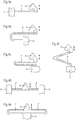
- FIGS. 2a to 2h are schematic views illustrating the inventive concept of a guidance with several degrees of freedom by means of a connection by an elastically flexible structure 2, 2 ', in particular by several flexible blades, between a rigid frame 6 and a rigid functional member 3
- Eight embodiments of a monolithic component with flexible blades, in these cases with a single functional member, are represented therein, in order to show by way of example at least part of the multitude of potentially achievable variants, given that it is not possible to describe here all the possible variants.
- the frames 6 are shown with crosses, the functional members 3 are shown hatched, and the blades 2, 2 'of the resiliently flexible structures do not have hatching since they are quite thin, rigid intermediate parts 7 can be part of the elastically flexible structures - as indicated schematically in the figures 2c and 2h - are grayed out.
- the rigid intermediate parts 7 are areas of the monolithic component which are markedly thicker than the areas constituting the flexible blades 2, 2 '.
- the actuator respectively the actuating finger 1, which impacts the rigid functional member 3, preferably at the end of the functional member 3 opposite its end in the form of an engaging hook.
- an elastically flexible structure - comprising at least two flexible blades 2, 2 'as well as optionally at least one rigid intermediate part 7 - between the rigid frame 6 and the functional member 3 allows a predefined displacement with at least two degrees of freedom of the latter.
- the presence of at least one bend at approximately 90 ° in at least one of the flexible blades 2, 2 'of the elastically flexible structure allows, respectively, considerably increases, the freedom of movement of the functional organ 3 in one of the directions of its movement.
- the flexible blade 2 of the embodiments of a monolithic component according to the figures 2a, 2b , 2d, 2e, 2f, and 2g forms an elbow at about 90 °.
- the functional member 3 of the corresponding monolithic component can not only move in a substantially horizontal direction in this plane, but, thanks to this bend, also a movement in one direction substantially vertical in this plane.
- the bend at approximately 90 ° is preferably formed on the flexible blade 2 located towards the end of the functional member 3 in the form of a hook which engages in the driven part 5 and therefore acts as a driving finger.
- an elastically flexible structure forms an elbow at approximately 90 ° by means of at least one rigid intermediate part 7, as illustrated in FIGS. figures 2c and 2h .
- the flexible blade 2 comprises several flexible parts oriented perpendicular to each other and separated by a rigid intermediate part 7.
- the flexible blade 2, which is formed by several parts separated by a rigid intermediate part 7 in order to form an elbow at approximately 90 ° is preferably located towards the end of the functional member 3 in the form of a hook engaging in the driven part 5 and therefore having the role of a trainer finger.
- the figures 2c and 2h show that a flexible blade 2 'or also 2 can be fixed either directly to the rigid frame 6 or to the rigid intermediate part 7.
- the figures 2a to 2h also indicate, schematically using the arrows and by way of example, types of combinations of movement achievable by a monolithic component according to the present invention which provides guidance with at least two degrees of freedom of a functional member rigid by means of a connection by an elastically flexible structure, in particular by at least two flexible blades, between a rigid frame and this rigid functional member.
- the figures 2a, 2b , 2d, 2e, 2f, and 2g show a monolithic component whose first resiliently flexible structure comprises flexible blades 2, 2 'configured so as to ensure a displacement of at least two degrees of freedom of said first drive member 3, that is to say of the functional organ, the two degrees of freedom of the predefined movement of the functional organ 3 consisting of a rotation combined with a movement according to a distant center of elasticity (CÉÉ / also called "remote center of compliance (RCC)).
- CÉÉ distant center of elasticity
- the figures 2c and 2h show a monolithic component whose first resiliently flexible structure comprises flexible blades 2, 2 'configured so as to ensure a displacement of at least two degrees of freedom of the functional member 3, the two degrees of freedom of the predefined movement of the functional member 3 consisting of two combined translations, respectively of a combined translation with a movement according to a distant center of elasticity.
- first resiliently flexible structure comprises flexible blades 2, 2 'configured so as to ensure a displacement of at least two degrees of freedom of the functional member 3, the two degrees of freedom of the predefined movement of the functional member 3 consisting of two combined translations, respectively of a combined translation with a movement according to a distant center of elasticity.
- the figure 3 shows a monolithic component according to the present invention capable of being integrated into an instantaneous date mechanism of a corresponding timepiece.
- This component is intended to fit into a kinematic chain such as that shown in figure 1 .
- the reference numbers and graphics are the same as above, as well as the structure and operation of the device, respectively of the kinematic chain, as explained in the context of the figure 1 .
- said driven part is a date disc / ring, preferably having teeth on its inner periphery
- the actuator is a control wheel equipped with an actuating finger, also not shown in figure 3
- said first drive member 3 is formed by a drive lever, one end of which is capable of being actuated by said actuating finger and of which the other end equipped with a drive finger is capable of s' engage in the teeth of said date ring in order to drive it in steps
- said second functional member 4 is a jumper capable of securing said date ring in its position, outside the phases of driving this ring by the first member drive 3.
- this monolithic component serves as a drive and securing member of a date disc / ring.
- a functional organ in in particular said second functional member serving as jumper 4
- this holding element can become, during a period of time during operation of the mechanism, a drive element.
- the general arrangement, respectively the operation, of an instantaneous date mechanism are known to those skilled in the art and will therefore not be described here, the description being limited to the monolithic component according to the present invention.
- the monolithic component shown on figure 3 allows itself to replace more than ten parts, including pins and axes, usually used in a date mechanism construction according to the state of the art.
- the figure 6 shows a basic kinematic diagram of a monolithic component according to the invention in which the flexible blades 2, 2 'have been replaced by rigid elements articulated at their ends by pivot connections. This component extends in a work plane which is that of the figures 1 to 3 .
- the kinematic diagram of the figure 6 corresponds to the embodiments presented on the figures 1 to 3 except for the figure 2c and will be used in the following to explain more generally the function of the parts of a monolithic component according to the present invention.
- the first elastically flexible structure of a monolithic component comprises a first flexible blade 2 extending between the frame 6 and the drive member 3 and defining a first point of embedding 32 at the level of the drive member 3.
- This first fitting point 32 is movable with reference to the frame 6 along a linear path with a degree of freedom situated in the work plane.
- This trajectory can be an arc of a circle as in the figures 2d, 2e, 2f, 2g, 2h or 6 .
- the shape of the flexible blade 2 may have two parts extending in substantially opposite directions so that the displacement of the point embedding 32 is substantially rectilinear as is the case in the embodiments presented in figures 1 , 2a , 2b and 3 .
- the flexibility of the blade 2 means that the rigid drive member 3 is movable in rotation with reference to the frame 6 about an axis perpendicular to the work plane.
- the first elastically flexible structure of a monolithic component according to the present invention comprises a second flexible blade 2 'defining a second embedding point 33 at the level of the drive member 3.
- the second flexible blade 2 ' comprises (in addition) two parts extending in substantially perpendicular directions and interconnected by an elbow 35 shown in figure 6 symbolically by a pivot link.
- the two parts of the second flexible blade 2 ' can be physically separated by a rigid intermediate part 7 as in the configuration of the figure 2h .
- the second embedding point 33 is movable with reference to the frame 6 along a plane path with two degrees of freedom located in the work plane.
- the invention is not limited to monolithic components of which the second flexible blade 2 ′ comprises two distinct parts separated by an elbow or a rigid intermediate part.
- the second flexible blade 2 ' can have any kind of geometry adapted so that the second blade 2' can flex, causing a displacement of the second embedding point 33 in the work plan.
- the first 32 and second 33 points of embedding of the first 2 and second 2 flexible blades in the first drive member 3 are arranged in different zones of said first drive member 3.
- the distance between the points d 'embedding 32 and 33 represents at least a quarter of the length of the flexible blade 2. More specifically, moving away the embedding points 32, 33 greatly increases the moment quadratic of the first flexible structure along an axis of the work plane, in other words, to improve the guidance of the first drive member 3 in the work plane.
- moving the mounting points 32, 33 away makes it possible to reduce the quadratic moment and therefore the section of each of the flexible blades.
- the drive means 34 is also remote from the embedding point 32 so that its movement takes place according to two degrees of freedom in the work plane. It is advantageous to provide stops cooperating with the first drive member 3 and / or the flexible arms 2, 2 ′ to limit the deformation of the elastically flexible structure to its elastic range.
- the stops can for example be integrated into the rigid frame 6.
- the deformations of the flexible blades 2, 2 ' are limited and define a work zone 36 in which the drive means 34 is mobile, illustrated schematically on figure 6 by a hatched area.
- the flexible blades 2, 2 'exert an elastic return force which tends to return the drive means 34 to a rest position substantially in the center of the work zone 36.
- the actuator 1 acting on the adapted portion 31 of the first drive member 3 causes a movement of the drive means 34 which describes a working path 37 shown, by way of example, on the figure 1 .
- the work path 37 delimits a non-zero surface by forming a loop, that is to say that the return path to the rest position is not superimposed on the outward path. This loop can be obtained e in response to movement of the actuator 1 only.
- the actuator 1 can, for example, be an eccentric guiding a circular movement of the adapted portion 31 which will cause a work path 37 in the form of a loop.
- the movement of the drive member 3 is also generated by the driven part 5. This is the case in the example of figure 1 where the driven part 5 deflects the outward path of the drive means 34, the drive means 34 sliding on a tooth of the driven part 5 until it passes it to drive it on the return path.
- the movement of the drive member 3 can also be generated by an additional guide element intended to come into contact with the first drive member 3 moving under the action. of the actuator.
- the additional guide element can come from the frame 6 or be fixed to a bridge, to the plate or to another element of the timepiece.
- the actuation of a mechanism by an actuating force capable of varying has several drawbacks. This is for example the case when a user actuates a mechanism directly using a control member.
- the mechanism must be sized to withstand the most powerful actuations, which may for example result from an impact on a push-button.
- additional safety devices may need to be provided to secure the position of moving parts.
- the actuating force also varies when the actuator of the mechanism is moved by the energy source of the timepiece, the motor torque of which varies according to the winding. In this second case, it will be necessary to ensure the operation of the mechanism over an extended range of actuation force which, in the case of positioning by a jumper, can complicate the design of the mechanism.
- the present invention makes it possible to remedy these drawbacks by proposing a monolithic component producing a constant force actuation device.
- the monolithic component according to the invention makes it possible to accumulate energy coming from the actuator in elastic form and to restore it with a constant force to the driven part, independently of the actuating force of the actuator. Indeed, the drive of the driven part 5 is caused only by the return to the rest position of the drive means 34 under the action of the flexible blades 2, 2 '.
- the indirect transmission of the actuating force using the monolithic component of the invention thus makes it possible to make the mechanisms to be actuated more reliable and secure and to simplify their design.
- FIGS. 4a to 4f are schematic views illustrating with the same reference numbers and graphics as above in the context of the figure 1 six embodiments of a second functional member 4, in particular of a holding member as used in the application illustrated in figure 3 .
- This retaining member 4 is connected to a part of a rigid frame 6 by means of a second elastically flexible structure, consisting of one or two blades 2.
- a second elastically flexible structure consisting of one or two blades 2.
- the flexible blade (s) 2 "of a second elastically flexible structure can be configured as a straight blade, a full or partial U-shaped, a full or partial V-shaped, or even a straight double blade, respectively a double U or V-shaped blade, or even a combinations of these configurations.
- the figure 5 shows a monolithic component constituting with the driven part an automatic winding mechanism capable of being integrated into a timepiece. Part numbers and graphics are the same as above, especially in the context of the figure 1 .
- this monolithic component is permanently attached to an actuator formed by an oscillating mass 1 ', so that the kinematic chain actuator - monolithic component - driven part is in this case achievable using only two separate physical parts, namely the monolithic component according to the present invention and the driven part.
- the oscillating weight 1 ' is connected to the frame 6 of the monolithic component by two flexible necks 2 "', that is to say by two short pieces having a central narrowing allowing them to bend and thus acting as a flexible blade.
- the frame 6 may include a bridge with a larger surface serving as an attachment point for said two flexible necks 2 '"connecting the two intermediate parts 7 to the frame 6 as well as a peripheral part of substantially circular shape surrounding said oscillating weight 1' and the rigid intermediate parts 7.
- Two other flexible necks 2 "' attached preferably close to the corresponding ends of the two intermediate parts 7 which are integral with the oscillating mass 1', connect said two rigid intermediate parts 7 of substantially straight shape to a third rigid intermediate part 7 of shape substantially square with a rounded angle.
- This third rigid intermediate part 7 is centrally located between said two rigid intermediate parts 7 of substantially straight shape arranged parallel to one another.
- the third rigid intermediate part 7 surrounds a winding wheel automatic 5, which in this application of the monolithic component forms the driven part, and carries two flexible blades 2, 2 'arranged tangentially with respect to said winding wheel 5.
- Each of the two flexible blades 2, 2' is terminated by a first member rigid drive 3, respectively by a second drive member 4, in particular by d hook-shaped drive pins 3, 4.
- each of the first and second rigid drive members 3, 4 is connected to the frame 6 by means of a corresponding first elastically flexible structure comprising two rigid intermediate parts 7 of substantially straight shape, a third rigid intermediate part 7 , four flexible necks 2 '"secured to the rigid intermediate parts 7 of straight shape and, in part, to the third rigid intermediate part 7, and a flexible blade 2, 2'.
- first elastically flexible structures which are distinguished only by the flexible blade 2 or 2 ', form a bend at about 90 °, analogously to what has been explained above with respect to figures 2c and 2h .
- the rigid functional members in the form of the drive fingers 3, 4 are able to engage in the teeth of the winding wheel 5 and both play, alternately, the role of drive finger when the mass 1 'oscillates from left to right and vice versa and that the two flexible blades 2, 2 'perform a corresponding movement.
- the monolithic component therefore drives using the drive fingers 3, 4, at each oscillation of sufficient amplitude of the oscillating weight 1 ', respectively at each sufficient movement of one of the two flexible blades 2, 2', the automatic winding wheel 5 in rotation, so that it turns one or more notch (s) in the direction of the arrow, depending on the amplitude of oscillation of the oscillating weight 1 '.
- the monolithic component can also be used by having only the first member. rigid drive 3.
- the general operation of an automatic winding mechanism is moreover known to those skilled in the art and will therefore not be described in more detail here.
- the monolithic component described above makes it possible to replace a set of at least a dozen parts constituting an automatic winding mechanism, for example of the Pellaton type, of the prior art.
- the drive means 34 constitutes a unidirectional drive device for the output mobile.
- the flexible structure is positioned between the frame 6 and the drive member so as to make the drive means 34 movable with reference to the frame according to two degrees of freedom in a work plane which is that of the figure in the example of figure 5 .
- the flexible structure may include rigid intermediate parts 7 as in the examples of figures 2c and 2h .
- At least one mass 1 ' is integral with the flexible structure.
- the mass can be added or be part of the monolithic component as in the example shown in figure 5 .
- the mass 1 ' is movable with reference to the frame according to at least one degree of freedom in the work plane.
- the elastic members of the flexible structure bring the mass towards a rest position so that together they constitute an oscillator.
- the accelerations supplied to the timepiece cause the displacement of the mass which in its movement causes the drive means 34 and consequently the driven member 5.
- the mass can be mobile in rotation or according to several degrees of freedom in the work plane.
- the monolithic component can be made of hardenable steel, preferably Durnico steel.
- it can be machined by wire cutting, by stamping, or by femtoprint which consists of a modification of the physical properties and a machining of transparent material by means of a femtosecond laser, followed by a hetching, but in all the cases so as to extend into a single plane.
- Other manufacturing techniques for such a monolithic component can be envisaged, for example, Liga, 3D printing, and all manufacturing processes related to silicon.
- the height of such a monolithic component is preferably found in a range of 0.1 mm to 5 mm and the width of the flexible blades of its first elastically flexible structure is found to be preferably within a range of 5 ⁇ m to 1 mm, but these values may also be somewhat outside these ranges.
- this monolithic component can be produced in a multitude of embodiments arranged differently according to the needs of the specific watchmaking application, so that it can be used for a considerable number of watchmaking applications.
- this monolithic component allows several important advantages to be achieved.
Description
La présente invention a pour objet un composant monolithique destiné à une pièce d'horlogerie, en particulier une pièce d'horlogerie mécanique, conçu pour transmettre le mouvement d'un actionneur de la pièce d'horlogerie à une pièce entraînée de la pièce d'horlogerie.The present invention relates to a monolithic component intended for a timepiece, in particular a mechanical timepiece, designed to transmit the movement of an actuator of the timepiece to a driven part of the timepiece. watchmaking.
Dans ce contexte, la demande de brevet
La demande de brevet
Le brevet japonais
La demande de brevet
La présente invention vise la diminution du nombre de composants constituant un mécanisme complet ou un sous-ensemble fonctionnel, en vue de diminuer les problèmes liés au frottement et aux jeux entre ces composants constituant un mécanisme horloger conventionnel, maîtriser les positionnements, et ainsi garantir la fiabilité du mécanisme. Plus spécifiquement, l'invention a pour but des composants monolithiques fonctionnels du type défini d'entrée, permettant la transmission d'énergie au moyen d'un entraînement le long de trajectoires de directions variées. Un autre but de l'invention est de proposer des composants monolithiques formant un organe de transmission à force constante qui permet une meilleure reproductibilité et une meilleure sécurité de l'actionnement de la pièce entrainée. De plus, l'invention a pour but de réaliser de tels composants monolithiques au moyen de techniques de fabrication connus de la construction horlogère.The present invention aims to reduce the number of components constituting a complete mechanism or a functional sub-assembly, with a view to reduce the problems associated with friction and the clearances between these components constituting a conventional horological mechanism, control the positioning, and thus guarantee the reliability of the mechanism. More specifically, the invention relates to functional monolithic components of the defined input type, allowing the transmission of energy by means of a drive along trajectories of various directions. Another object of the invention is to provide monolithic components forming a constant force transmission member which allows better reproducibility and better safety of the actuation of the driven part. In addition, the aim of the invention is to produce such monolithic components by means of manufacturing techniques known to watchmaking construction.
La présente invention propose à cet effet des composants monolithiques destinés à une pièce d'horlogerie, en particulier une pièce d'horlogerie mécanique, comprenant au moins une partie rigide et une partie élastiquement flexible et conçus pour transmettre le mouvement d'un actionneur de la pièce d'horlogerie à une pièce entraînée de la pièce d'horlogerie, lesdits composants monolithiques comprenant
- un bâti rigide,
- un premier organe d'entraînement rigide, et
- une première structure élastiquement flexible reliant ledit bâti avec ledit premier organe d'entraînement,
- a rigid frame,
- a first rigid drive member, and
- a first elastically flexible structure connecting said frame with said first drive member,
La présente invention propose donc des composants monolithiques formés d'une pluralité de zones rigides et de zones flexibles. Les termes « rigide » et « flexible » sont à comprendre ici dans le cadre du domaine horloger, c'est-à-dire qu'une zone flexible subit une flexion suffisante pour la transmission de mouvement désirée sous l'effet de la force mécanique que l'actionneur est capable de produire, alors que dans cette situation une zone rigide ne se déforme pas significativement.The present invention therefore proposes monolithic components formed from a plurality of rigid zones and of flexible zones. The terms “rigid” and “flexible” are to be understood here within the framework of the watchmaking field, that is to say that a flexible zone undergoes sufficient bending for the desired transmission of movement under the effect of mechanical force. that the actuator is capable of producing, while in this situation a rigid zone does not deform significantly.
Dans le cadre de l'invention, l'actionneur peut être une pièce indépendante du composant monolithique, entrant en contact avec ledit premier organe d'entraînement pour générer les dits déplacements. L'actionneur peut également être solidaire du composant monolithique.In the context of the invention, the actuator can be a part independent of the monolithic component, coming into contact with said first drive member to generate said movements. The actuator can also be integral with the monolithic component.
Les composantes dudit déplacement à deux degrés de liberté sont choisies parmi les translations, les rotations et leurs combinaisons.The components of said displacement with two degrees of freedom are chosen from among translations, rotations and their combinations.
La première structure élastiquement flexible peut comprendre deux lames flexibles s'étendant chacune entre ledit bâti et ledit premier organe d'entraînement.The first resiliently flexible structure may comprise two flexible blades each extending between said frame and said first drive member.
Les points de contact des deux lames flexibles avec le premier organe d'entraînement peuvent être agencés dans des zones différentes dudit premier organe d'entraînement. L'une des deux dites lames flexibles peut comprendre une portion coudée sensiblement à angle droit.The points of contact of the two flexible blades with the first drive member can be arranged in different zones of said first drive member. One of the two said flexible blades may comprise a portion bent substantially at right angles.
Une partie intermédiaire rigide peut être agencée entre deux portions flexibles de la structure flexible.A rigid intermediate part can be arranged between two flexible portions of the flexible structure.
La première structure élastiquement flexible peut aussi comprendre un ou plusieurs cols flexibles agencé(s) entre deux éléments rigides dudit composant monolithique.The first resiliently flexible structure can also comprise one or more flexible necks arranged between two rigid elements of said monolithic component.
Selon une forme d'exécution de l'invention, le composant monolithique comprend, de préférence, un deuxième organe fonctionnel et une deuxième structure élastiquement flexible reliant ledit bâti audit deuxième organe fonctionnel, ladite deuxième structure élastiquement flexible étant configurée de façon à mettre ledit deuxième organe fonctionnel en contact avec une pièce entraînée.According to one embodiment of the invention, the monolithic component preferably comprises a second functional member and a second elastically flexible structure connecting said frame to said second functional member, said second elastically flexible structure being configured so as to place said second functional organ in contact with a driven part.
Selon une forme d'exécution de l'invention, ledit deuxième organe fonctionnel est un organe de maintien, configuré pour sécuriser temporairement une pièce entraînée par ledit premier organe d'entraînement dans sa position.According to one embodiment of the invention, said second functional member is a holding member, configured to temporarily secure a part driven by said first drive member in its position.
Dans une application de l'invention, ladite pièce entraînée est un disque denté, l'actionneur est une roue de commande équipée d'un doigt d'entraînement, ledit premier organe d'entraînement est une bascule, et ledit deuxième organe fonctionnel est un sautoir.In one application of the invention, said driven part is a toothed disc, the actuator is a control wheel equipped with a drive finger, said first drive member is a rocker, and said second functional member is a saltire.
Dans une autre application de l'invention, le composant monolithique constitue un mécanisme de remontage automatique, intégrant une masse oscillante en tant qu'actionneur, la pièce entraînée étant une roue de remontage automatique, et ledit premier organe d'entraînement comprenant deux doigts qui jouent tous deux, alternativement, le rôle de doigt entraîneur.In another application of the invention, the monolithic component constitutes an automatic winding mechanism, incorporating an oscillating mass as an actuator, the driven part being an automatic winding wheel, and said first drive member comprising two fingers which both play, alternately, the role of coach finger.
Les composants précités sont de préférence réalisés en aciers durcissables, encore appelés aciers maraging, par exemple en acier Durnico. De tels matériaux, en feuilles ou tôles fines, peuvent être usinés par découpage au fil, par étampage, ou encore par femtoprint pour réaliser des composants s'étendant dans un seul plan.The aforementioned components are preferably made of hardenable steels, also called maraging steels, for example Durnico steel. Such materials, in sheets or thin sheets, can be machined by wire cutting, by stamping, or even by femtoprint to produce components extending in a single plane.
L'invention sera maintenant décrite en détail en référence aux dessins annexés illustrant à titre d'exemple plusieurs formes d'exécution de l'invention.The invention will now be described in detail with reference to the accompanying drawings illustrating by way of example several embodiments of the invention.
Les dessins annexés représentent schématiquement et à titre d'exemples plusieurs formes d'exécution de l'invention.
- La
figure 1 est une vue schématique de dessus illustrant à titre d'exemple une chaîne cinématique actionneur - composant monolithique - pièce entraînée réalisée en utilisant un composant monolithique selon la présente invention. - Les
figures 2a à 2h sont des vues schématiques montrant huit variantes d'exécution d'un composant monolithique à lames flexibles selon la présente invention. - La
figure 3 montre un composant monolithique selon la présente invention apte à être intégré dans un mécanisme de quantième instantané. - Les
figures 4a à 4f sont des vues schématiques montrant six variantes d'exécution d'un organe de maintien avec sa structure flexible pouvant faire partie d'un composant monolithique selon la présente invention. - La
figure 5 montre un mécanisme de remontage automatique comportant un composant monolithique selon la présente invention. - La
figure 6 représente un schéma cinématique des modes de réalisation d'un composant monolithique selon la présente invention présentés auxfigures 1 ,2 et3 .
- The
figure 1 is a schematic top view illustrating by way of example an actuator kinematic chain - monolithic component - driven part produced using a monolithic component according to the present invention. - The
figures 2a to 2h are schematic views showing eight variant embodiments of a monolithic component with flexible blades according to the present invention. - The
figure 3 shows a monolithic component according to the present invention capable of being integrated into an instantaneous date mechanism. - The
figures 4a to 4f are schematic views showing six alternative embodiments of a retaining member with its flexible structure which can form part of a monolithic component according to the present invention. - The
figure 5 shows an automatic winding mechanism comprising a monolithic component according to the present invention. - The
figure 6 represents a kinematic diagram of the embodiments of a monolithic component according to the present invention presented infigures 1 ,2 and3 .
Les mêmes numéros de référence et les mêmes graphismes (hachures, croix, grisé, ...) sont utilisés dans l'ensemble des figures pour désigner des éléments identiques ou similaires.The same reference numbers and the same graphics (hatching, cross, gray, ...) are used in all the figures to designate identical or similar elements.
La
Lors de l'opération de la pièce d'horlogerie correspondante intégrant une chaîne cinématique telle qu'illustrée à la
Par conséquent, une chaîne cinématique telle que montrée à titre d'exemple à la
Les
En examinant ces figures, l'homme du métier comprendra aisément que l'agencement d'une structure élastiquement flexible - comprenant au moins deux lames flexibles 2, 2' ainsi qu'éventuellement au moins une partie intermédiaire rigide 7 - entre le bâti rigide 6 et l'organe fonctionnel 3 permet un déplacement prédéfini à au moins deux degrés de liberté de ce dernier. L'homme du métier notera en particulier que la présence d'au moins un coude à environ 90° dans au moins une des lames flexibles 2, 2' de la structure élastiquement flexible permet, respectivement augmente considérablement, la liberté de déplacement de l'organe fonctionnel 3 dans l'une des directions de son déplacement. Par exemple, la lame flexible 2 des formes d'exécution d'un composant monolithique selon les
Les
La
La
Ainsi, de façon générale, la première structure élastiquement flexible d'un composant monolithique selon la présente invention comporte une première lame flexible 2 s'étendant entre le bâti 6 et l'organe d'entraînement 3 et définissant un premier point d'encastrement 32 au niveau de l'organe d'entraînement 3. Ce premier point d'encastrement 32 est mobile en référence au bâti 6 selon une trajectoire linéaire à un degré de liberté située dans le plan de travail. Cette trajectoire peut être un arc de cercle comme dans les
De plus, la première structure élastiquement flexible d'un composant monolithique selon la présente invention comporte une deuxième lame flexible 2' définissant un second point d'encastrement 33 au niveau de l'organe d'entraînement 3. Dans les modes de réalisation présentés par exemple aux
Les premier 32 et second 33 points d'encastrement des première 2 et deuxième 2' lames flexibles dans le premier organe d'entraînement 3 sont agencés dans des zones différentes dudit premier organe d'entraînement 3. De préférence, l'éloignement des points d'encastrement 32 et 33 représente au moins un quart de la longueur de la lame flexible 2. Plus concrètement, éloigner les points d'encastrement 32, 33 permet de fortement augmenter le moment quadratique de la première structure flexible selon un axe du plan de travail, autrement dit, d'améliorer le guidage du premier organe d'entrainement 3 dans le plan de travail. Alternativement, pour une même rigidité du premier organe d'entrainement 3 dans le plan de travail, éloigner les points d'encastrement 32, 33 permet de réduire le moment quadratique et donc la section de chacune des lames flexibles.The first 32 and second 33 points of embedding of the first 2 and second 2 flexible blades in the
De préférence, le moyen d'entrainement 34 est également éloigné du point d'encastrement 32 afin que son déplacement s'effectue selon deux degrés de liberté dans le plan de travail. Il est avantageux de prévoir des butées coopérant avec le premier organe d'entrainement 3 et/ou les bras flexibles 2, 2' pour limiter la déformation de la structure élastiquement flexible à son domaine élastique. Les butées peuvent par exemple être intégrées au bâti rigide 6. Avec ou sans butées, les déformations des lames flexibles 2, 2' sont limitées et définissent une zone de travail 36 dans laquelle le moyen d'entrainement 34 est mobile, illustrée schématiquement à la
L'actionneur 1 agissant sur la portion adaptée 31 du premier organe d'entraînement 3 provoque un déplacement du moyen d'entraînement 34 qui décrit une trajectoire de travail 37 représentée, à titre d'exemple, sur la
Dans d'autres formes de réalisation, le déplacement de l'organe d'entraînement 3 est également engendré par la pièce entraînée 5. C'est le cas dans l'exemple de la
Dans encore d'autres formes de réalisation non représentées, le déplacement de l'organe d'entrainement 3 peut également être engendré par un élément de guidage supplémentaire destiné à entrer en contact avec le premier organe d'entrainement 3 se déplaçant sous l'action de l'actionneur. L'élément de guidage supplémentaire peut être issu du bâti 6 ou être fixé à un pont, à la platine ou un autre élément de la pièce d'horlogerie.In yet other embodiments not shown, the movement of the
D'une façon générale, l'actionnement d'un mécanisme par une force d'actionnement susceptible de varier présente plusieurs inconvénients. C'est par exemple le cas quand un utilisateur actionne un mécanisme directement à l'aide d'un organe de commande. Le mécanisme doit être dimensionné pour supporter les actionnements les plus puissants, qui peuvent par exemple résulter d'un choc sur un poussoir. De plus, des dispositifs de sécurité supplémentaires doivent éventuellement être prévus pour sécuriser la position des pièces en mouvement.In general, the actuation of a mechanism by an actuating force capable of varying has several drawbacks. This is for example the case when a user actuates a mechanism directly using a control member. The mechanism must be sized to withstand the most powerful actuations, which may for example result from an impact on a push-button. In addition, additional safety devices may need to be provided to secure the position of moving parts.
La force d'actionnement varie également quand l'actionneur du mécanisme est mû par la source d'énergie de la pièce d'horlogerie dont le couple moteur varie en fonction du remontage. Dans ce deuxième cas, on devra assurer le fonctionnement du mécanisme sur une plage d'effort d'actionnement étendue ce qui, dans le cas d'un positionnement par un sautoir, peut compliquer la conception du mécanisme.The actuating force also varies when the actuator of the mechanism is moved by the energy source of the timepiece, the motor torque of which varies according to the winding. In this second case, it will be necessary to ensure the operation of the mechanism over an extended range of actuation force which, in the case of positioning by a jumper, can complicate the design of the mechanism.
La présente invention permet de remédier à ces inconvénients en proposant un composant monolithique réalisant un dispositif d'actionnement à force constante. Le composant monolithique selon l'invention permet d'accumuler de l'énergie provenant de l'actionneur sous forme élastique et de la restituer avec une force constante à la pièce entraînée, indépendamment de la force d'actionnement de l'actionneur. En effet, l'entraînement de la pièce entraînée 5 est provoqué uniquement par le retour à la position de repos du moyen d'entrainement 34 sous l'action des lames flexibles 2, 2'. La transmission indirecte de la force d'actionnement à l'aide du composant monolithique de l'invention permet ainsi de fiabiliser et sécuriser les mécanismes à actionner et de simplifier leur conception.The present invention makes it possible to remedy these drawbacks by proposing a monolithic component producing a constant force actuation device. The monolithic component according to the invention makes it possible to accumulate energy coming from the actuator in elastic form and to restore it with a constant force to the driven part, independently of the actuating force of the actuator. Indeed, the drive of the driven
Les
La
Deux autres cols flexibles 2"', attachés de préférence proche des extrémités correspondantes des deux parties intermédiaires 7 qui sont solidaires de la masse oscillante 1', relient lesdites deux parties intermédiaires rigides 7 de forme sensiblement droite à une troisième partie intermédiaire rigide 7 de forme sensiblement carrée avec un angle arrondi. Cette troisième partie intermédiaire rigide 7 est située de manière centrale entre lesdites deux parties intermédiaires rigides 7 de forme sensiblement droite agencées parallèlement l'une à l'autre. La troisième partie intermédiaire rigide 7 entoure une roue du remontage automatique 5, qui forme dans cette application du composant monolithique la pièce entraînée, et porte deux lames flexibles 2, 2' agencées tangentiellement par rapport à ladite roue du remontage 5. Chacune des deux lames flexibles 2, 2' est terminée par un premier organe d'entraînement rigide 3, respectivement par un deuxième organe d'entraînement 4, notamment par des doigts d'entraînement 3, 4 en forme de crochet. Par conséquent, chacun des premier et deuxième organes d'entraînement rigides 3, 4 est relié au bâti 6 à l'aide d'une première structure élastiquement flexible correspondante comportant deux parties intermédiaires rigides 7 de forme sensiblement droite, une troisième partie intermédiaire rigide 7, quatre cols flexibles 2'" solidaires des parties intermédiaires rigides 7 de forme droite et, en partie, de la troisième partie intermédiaire rigide 7, et une lame flexible 2, 2'. Il est à noter dans ce contexte que chacune de ces premières structures élastiquement flexibles, qui ne se distinguent que par la lame flexible 2 ou 2', forme un coude à environ 90°, de façon analogique à ce qui a été expliqué ci-dessus par rapport aux
Ainsi, les organes fonctionnels rigides sous forme des doigts d'entraînement 3, 4 sont aptes à s'engager dans la denture de la roue du remontage 5 et jouent tous deux, alternativement, le rôle de doigt entraîneur lorsque la masse 1' oscille de gauche à droite et inversement et que les deux lames flexibles 2, 2' effectuent un mouvement correspondant. Le composant monolithique entraîne donc à l'aide des doigts d'entraînement 3, 4, à chaque oscillation d'amplitude suffisante de la masse oscillante 1', respectivement à chaque mouvement suffisant d'une des deux lames flexibles 2, 2', la roue du remontage automatique 5 en rotation, de manière à ce qu'elle tourne d'un ou plusieurs cran(s) dans le sens de la flèche, en fonction de l'amplitude d'oscillation de la masse oscillante 1'. Il reste à noter dans ce contexte que la présence du deuxième organe d'entraînement rigide 4 est optionnelle dans ce composant monolithique, afin d'augmenter l'efficacité du remontage automatique, le composant monolithique pouvant aussi être utilisé en ne disposant que du premier organe d'entraînement rigide 3. Le fonctionnement général d'un mécanisme à remontage automatique est par ailleurs connu de l'homme du métier et ne sera par conséquent pas décrit plus en détail ici. Dans cette application également, le composant monolithique décrit ci-dessus permet de remplacer un ensemble d'au moins une douzaine de pièces constituant un mécanisme de remontage automatique, par exemple de type Pellaton, de l'art antérieur.Thus, the rigid functional members in the form of the
D'une façon générale, le composant monolithique selon l'invention permettant de réaliser un mécanisme de remontage automatique comporte un bâti 6, une structure flexible et un organe d'entraînement 3 comportant un moyen d'entraînement 34 apte à coopérer avec un organe entraîné 5 du mécanisme, en l'occurrence un mobile de sortie. Le moyen d'entraînement 34 constitue un dispositif d'entraînement unidirectionnel du mobile de sortie. La structure flexible est positionnée entre le bâti 6 et l'organe d'entraînement de manière à rendre le moyen d'entraînement 34 mobile en référence au bâti selon deux degrés de liberté dans un plan de travail qui est celui de la figure dans l'exemple de la
Au moins une masse 1' est solidaire de la structure flexible. La masse peut être rapportée ou faire partie du composant monolithique comme dans l'exemple représenté à la
De nombreuses configurations reprenant ces caractéristiques communes sont possibles. En particulier la masse peut être mobile en rotation ou selon plusieurs degrés de liberté dans le plan de travail.Numerous configurations incorporating these common characteristics are possible. In particular, the mass can be mobile in rotation or according to several degrees of freedom in the work plane.
Indépendamment de l'application pour laquelle le composant monolithique est utilisé, il peut être réalisé en acier durcissable, de préférence en acier Durnico. Par ailleurs, il peut être usiné par découpage au fil, par étampage, ou par femtoprint qui consiste en une modification des propriétés physiques et un usinage de matière transparente par l'intermédiaire d'un laser femtoseconde, suivi d'un hetching, mais dans tous les cas de sorte à s'étendre dans un seul plan. D'autres techniques de fabrication d'un tel composant monolithique sont envisageables, par exemple, Liga, impression 3D, et tous les procédés de fabrication liés au silicium. Par ailleurs, la hauteur d'un tel composant monolithique se trouve, de préférence, dans une plage allant de 0.1 mm à 5 mm et la largeur des lames flexibles de sa première structure élastiquement flexible se trouve, de préférence, dans une plage allant de 5 µm à 1 mm, mais ces valeurs peuvent aussi se trouver quelque peu en dehors de ces plages.Regardless of the application for which the monolithic component is used, it can be made of hardenable steel, preferably Durnico steel. In addition, it can be machined by wire cutting, by stamping, or by femtoprint which consists of a modification of the physical properties and a machining of transparent material by means of a femtosecond laser, followed by a hetching, but in all the cases so as to extend into a single plane. Other manufacturing techniques for such a monolithic component can be envisaged, for example, Liga, 3D printing, and all manufacturing processes related to silicon. Furthermore, the height of such a monolithic component is preferably found in a range of 0.1 mm to 5 mm and the width of the flexible blades of its first elastically flexible structure is found to be preferably within a range of 5 µm to 1 mm, but these values may also be somewhat outside these ranges.
Au vue de la description figurant ci-dessus du principe d'un composant monolithique selon la présente invention, des options au niveau de ses parties, ainsi que des deux applications d'un tel composant monolithique mentionnées à titre d'exemple, il est évident, d'une part, que ce composant monolithique peut être réalisé dans une multitude de formes d'exécution agencées différemment en fonction des besoins de l'application horlogère spécifique, donc qu'il peut servir à un nombre considérable d'applications horlogères. D'autre part, aussi longtemps que le composant monolithique est agencé selon les principes énoncés ci-dessus et, en particulier, de manière à ce que ladite première structure élastiquementflexible liant le premier organe d'entraînement rigide au bâti rigide est configurée de façon à assurer un déplacement à au moins deux degrés de liberté dudit premier organe d'entraînement, ce composant monolithique permet de réaliser plusieurs avantages importants. Il permet effectivement de diminuer le nombre de composants constituant un mécanisme complet ou un sous-ensemble fonctionnel d'une pièce horlogère correspondante, ce qui diminue simultanément les problèmes liés au frottement et aux jeux entre ces composants, comme des axes ou des goupilles, constituant un mécanisme horloger conventionnel. En même temps, cela permet, du fait de disposer d'une seule pièce physique agencée dans un seul plan, de mieux maîtriser les positionnements et ainsi de garantir la fiabilité du mécanisme ainsi que d'optimiser l'épaisseur d'un composant horloger correspondant. Il en résulte une transmission d'énergie au moyen d'un entraînement le long de trajectoires prédéfinies ayant au moins deux degrés de liberté dans le plan du mouvement, ces trajectoires pouvant être simples ou plus complexes et de directions variées en fonction de l'agencement du composant monolithique, respectivement de ses lames flexibles. De plus, de tels composants monolithiques peuvent être réalisés au moyen de matériaux et de techniques de fabrication connus de la construction horlogère, donc à un coût modéré, toute en ayant un aspect esthétique attractif afin d'être utilisables dans la haute horlogerie.In view of the description given above of the principle of a monolithic component according to the present invention, of the options at the level of its parts, as well as of the two applications of such a monolithic component mentioned by way of example, it is obvious , on the one hand, that this monolithic component can be produced in a multitude of embodiments arranged differently according to the needs of the specific watchmaking application, so that it can be used for a considerable number of watchmaking applications. On the other hand, as long as the monolithic component is arranged according to the principles set out above and, in particular, so that said first elastically flexible structure linking the first rigid drive member to the rigid frame is configured so as to ensuring a movement with at least two degrees of freedom of said first drive member, this monolithic component allows several important advantages to be achieved. It effectively reduces the number of components constituting a complete mechanism or a functional sub-assembly of a corresponding timepiece, which simultaneously reduces the problems associated with friction and the clearances between these components, such as axes or pins, constituting a conventional watch mechanism. At the same time, this makes it possible, because of having a single physical part arranged in a single plane, to better control the positioning and thus to guarantee the reliability of the mechanism as well as to optimize the thickness of a corresponding watch component. . This results in a transmission of energy by means of a drive along predefined paths having at least two degrees of freedom in the plane of the movement, these paths possibly being simple or more complex and of various directions depending on the arrangement. of the monolithic component, respectively of its flexible blades. In addition, such monolithic components can be made using materials and techniques. manufacture known to the watchmaking industry, therefore at a moderate cost, while having an attractive aesthetic appearance in order to be usable in fine watchmaking.
Claims (15)
- A monolithic component for a timepiece, in particular for a mechanical timepiece, designed to transmit the movement of an actuator (1, 1') of the timepiece to a driven part (5) of the timepiece, characterized in that said monolithic component comprises- a rigid frame (6),- a first rigid driving member (3), and- a first elastically flexible structure (2, 2', 2"', 7) connecting said frame (6) to said first driving member (3),and in that said first elastically flexible structure (2, 2', 2"', 7) is configured in a manner such as to provide a displacement of said first driving member (3) with at least two degrees of freedom, said displacement being caused under the effect of the actuator (1, 1').
- The monolithic component according to claim 1, characterized in that the displacement is caused as a result of a contact of the first driving member (3) with the driven part (5).
- The monolithic component according to one of the preceding claims, characterized in that the displacement is caused as a result of a contact of the first driving member (3) with a supplementary guide element.
- The monolithic component according to one of the preceding claims, characterized in that said actuator (1) is an independent part which is adapted to come into contact with said monolithic component in order to cause said displacement.
- The monolithic component according to one of claims 1 to 3, characterized in that said actuator (1') is integral with said monolithic component.
- The monolithic component according to one of the preceding claims, characterized in that the components of said displacement with at least two degrees of freedom are selected from translations, rotations, movements according to a remote centre of compliance (RCC) and combinations thereof.
- The monolithic component according to one of the preceding claims, characterized in that said first elastically flexible structure comprises two flexible strips (2, 2') each extending between said frame (6) and said first driving member (3).
- The monolithic component according to the preceding claim, characterized in that the points of contact of the two flexible strips (2, 2') with the first driving member (3) are arranged in different zones of said first driving member (3).
- The monolithic component according to one of the preceding claims 7 or 8, characterized in that one of the two said flexible strips (2, 2') comprises an elbowed portion which is angled substantially at a right angle.
- The monolithic component according to one of the preceding claims, characterized in that an intermediate rigid portion (7) is arranged between two flexible portions of said first elastically flexible structure, in particular between two portions of the flexible strips (2, 2') of this first elastically flexible structure.
- The monolithic component according to one of the preceding claims, characterized in that said first elastically flexible structure comprises one or more flexible necks (2"') arranged between two rigid elements (6, 7) of said monolithic component.
- The monolithic component according to one of the preceding claims, characterized in that it comprises a second functional member (4) and a second elastically flexible structure (2") connecting said frame (6) to said second functional member (4), said second elastically flexible structure (2") being configured in a manner such as to place said second functional member (4) in contact with a driven part.
- The monolithic component according to the preceding claim, characterized in that said driven part (5) is a date disc or ring, in that the actuator is a control wheel equipped with a driving finger (1), in that said rigid first driving member (3) is a yoke connected to the rigid frame (6) via a first elastically flexible structure comprising flexible strips (2, 2'), and in that said second functional member (4) is a jumper connected to the rigid frame (6) via a second elastically flexible structure (2"), in a manner such that said monolithic component acts as a driving member and securing member of a date disc or ring of a date mechanism of the respective timepiece.
- The monolithic component according to one of the preceding claims 1 to 11, characterized in that said driven part (5) is an automatic winding wheel, in that the actuator is an oscillating mass (1') integral with the monolithic component, and in that said first rigid driving member (3) comprises two driving fingers (3, 4) which are each connected to the rigid frame (6) via a first elastically flexible structure comprising flexible strips (2, 2', 2"') as well as rigid intermediate portions (7) and which both are adapted to act in alternation as the driving means which is adapted to drive said automatic winding wheel, in a manner such that said monolithic component acts as a driving member for a winding wheel of an automatic winding mechanism of the respective timepiece.
- A timepiece, in particular a mechanical timepiece, characterized in that it comprises a monolithic component according to one of the preceding claims.
Applications Claiming Priority (2)
| Application Number | Priority Date | Filing Date | Title |
|---|---|---|---|
| CH01737/16A CH713288A1 (en) | 2016-12-23 | 2016-12-23 | Flexible monolithic component for timepiece. |
| PCT/EP2017/083646 WO2018115014A2 (en) | 2016-12-23 | 2017-12-19 | Flexible monolithic component for a timepiece |
Publications (2)
| Publication Number | Publication Date |
|---|---|
| EP3559755A2 EP3559755A2 (en) | 2019-10-30 |
| EP3559755B1 true EP3559755B1 (en) | 2020-11-11 |
Family
ID=60935831
Family Applications (1)
| Application Number | Title | Priority Date | Filing Date |
|---|---|---|---|
| EP17825498.3A Active EP3559755B1 (en) | 2016-12-23 | 2017-12-19 | Flexible monolithic component for timepiece |
Country Status (6)
| Country | Link |
|---|---|
| US (1) | US20190332061A1 (en) |
| EP (1) | EP3559755B1 (en) |
| JP (1) | JP7105779B2 (en) |
| CN (1) | CN109952541B (en) |
| CH (1) | CH713288A1 (en) |
| WO (1) | WO2018115014A2 (en) |
Families Citing this family (11)
| Publication number | Priority date | Publication date | Assignee | Title |
|---|---|---|---|---|
| EP3644129A1 (en) * | 2018-10-24 | 2020-04-29 | Patek Philippe SA Genève | Flexible guide member |
| JP7240877B2 (en) * | 2019-01-07 | 2023-03-16 | シチズン時計株式会社 | Time difference correction mechanism and clock with time difference correction mechanism |
| CH715864B1 (en) * | 2019-02-19 | 2022-08-15 | Richemont Int Sa | Blocking device for a watch movement. |
| NL2023420B1 (en) * | 2019-07-02 | 2021-02-02 | Flexous Mech Ip B V | Watch or timepiece |
| NL2023823B1 (en) * | 2019-09-12 | 2021-05-17 | Flexous Mech Ip B V | Watch |
| EP3795855A1 (en) * | 2019-09-20 | 2021-03-24 | Patek Philippe SA Genève | Method for producing a timepiece spring from monocrystalline material and timepiece spring obtained by said method |
| CH716983A1 (en) | 2019-12-20 | 2021-06-30 | Mft Dhorlogerie Audemars Piguet Sa | Watch mechanism intended to be driven in a variable number of steps. |
| EP3919988A1 (en) * | 2020-06-04 | 2021-12-08 | Montres Breguet S.A. | Articulated timepiece mechanism with flexible guiding |
| EP4215999A1 (en) | 2022-01-24 | 2023-07-26 | Flexous Mechanisms IP B.V. | Energy harvester for a wearable and/or portable device |
| WO2023248178A1 (en) | 2022-06-23 | 2023-12-28 | Lvmh Swiss Manufactures Sa | Bistable timepiece control mechanism |
| WO2023248177A1 (en) | 2022-06-23 | 2023-12-28 | Lvmh Swiss Manufactures Sa | Bistable timepiece control mechanism |
Family Cites Families (16)
| Publication number | Priority date | Publication date | Assignee | Title |
|---|---|---|---|---|
| JPS52139468A (en) * | 1976-05-17 | 1977-11-21 | Seiko Instr & Electronics Ltd | Calendar correcting mechanism for timepiece |
| CH695802A5 (en) | 2001-10-23 | 2006-08-31 | Franck Muller Watchland Sa | Control device for a timepiece. |
| JP4386022B2 (en) * | 2004-11-10 | 2009-12-16 | セイコーエプソン株式会社 | Clock display device, movement, and clock |
| JP2008058012A (en) * | 2006-08-29 | 2008-03-13 | Seiko Instruments Inc | Gear with jumper for timepiece, gear structure with slip mechanism for timepiece, time correcting structure and time difference correcting timepiece |
| JP4917909B2 (en) | 2007-02-15 | 2012-04-18 | セイコーインスツル株式会社 | Jumper structure, calendar mechanism provided with the same, and watch with calendar mechanism |
| CH708113B1 (en) * | 2007-09-13 | 2014-12-15 | Stéphane Von Gunten | Anchor for a watch escapement. |
| EP2105806B1 (en) * | 2008-03-27 | 2013-11-13 | Sowind S.A. | Escapement mechanism |
| EP2818941A1 (en) * | 2010-04-01 | 2014-12-31 | Rolex Sa | Device for locking a sprocket wheel |
| JP5551312B2 (en) | 2010-07-19 | 2014-07-16 | ニヴァロックス−ファー ソシエテ アノニム | Oscillation mechanism with elastic pivot and movable element for energy transfer |
| CN104204966B (en) * | 2012-03-29 | 2017-02-22 | 尼瓦洛克斯-法尔股份有限公司 | Flexible escapement mechanism having a mobile frame |
| EP2730980B1 (en) * | 2012-11-09 | 2018-08-29 | Nivarox-FAR S.A. | Clockwork limitation or transmission mechanism |
| EP2781969B1 (en) * | 2013-03-19 | 2017-05-03 | Nivarox-FAR S.A. | Non-removable one-piece timepiece component |
| JP6494266B2 (en) * | 2013-12-13 | 2019-04-03 | ロレックス・ソシエテ・アノニムRolex Sa | Jumper for clockwork movement |
| EP2977830B1 (en) * | 2014-07-23 | 2017-08-30 | Nivarox-FAR S.A. | Constant-force escapement mechanism |
| EP3032351A1 (en) * | 2014-12-09 | 2016-06-15 | LVMH Swiss Manufactures SA | Timepiece mechanism, timepiece movement and timepiece having such a mechanism |
| EP3054357A1 (en) * | 2015-02-03 | 2016-08-10 | ETA SA Manufacture Horlogère Suisse | Clock oscillator mechanism |
-
2016
- 2016-12-23 CH CH01737/16A patent/CH713288A1/en not_active Application Discontinuation
-
2017
- 2017-12-19 US US16/349,952 patent/US20190332061A1/en active Pending
- 2017-12-19 EP EP17825498.3A patent/EP3559755B1/en active Active
- 2017-12-19 JP JP2019532972A patent/JP7105779B2/en active Active
- 2017-12-19 CN CN201780069215.0A patent/CN109952541B/en active Active
- 2017-12-19 WO PCT/EP2017/083646 patent/WO2018115014A2/en unknown
Also Published As
| Publication number | Publication date |
|---|---|
| JP7105779B2 (en) | 2022-07-25 |
| CN109952541B (en) | 2021-05-07 |
| EP3559755A2 (en) | 2019-10-30 |
| CN109952541A (en) | 2019-06-28 |
| WO2018115014A2 (en) | 2018-06-28 |
| US20190332061A1 (en) | 2019-10-31 |
| JP2020502525A (en) | 2020-01-23 |
| CH713288A1 (en) | 2018-06-29 |
| WO2018115014A3 (en) | 2018-10-18 |
Similar Documents
| Publication | Publication Date | Title |
|---|---|---|
| EP3559755B1 (en) | Flexible monolithic component for timepiece | |
| JP5213364B2 (en) | Micromechanical movable element whose rotation is controlled by collision | |
| EP3206089B1 (en) | Timepiece resonator mechanism | |
| EP3182213B1 (en) | Mechanism for adjusting an average speed in a clock movement and clock movement | |
| CH709920A2 (en) | Set of mobile watch braking. | |
| EP3457221A2 (en) | Timepiece oscillator with flexible pivot | |
| CH709508B1 (en) | Watch movement with a drive mechanism of an analogue indicator with periodic or intermittent movement. | |
| FR3059792A1 (en) | DEVICE FOR WATCHMAKING PART, CLOCK MOVEMENT AND TIMEPIECE COMPRISING SUCH A DEVICE | |
| CH709328B1 (en) | Escapement, timepiece movement and timepiece. | |
| EP2781967A1 (en) | Timepiece hairspring | |
| EP0580049B1 (en) | Piezo-electric motor | |
| CH685660B5 (en) | Timepiece provided with drive means forms by a piezoelectric motor. | |
| EP1870784B1 (en) | Micro-mechanical wheel with impact-controlled rotation | |
| EP3598242A1 (en) | Cam timepiece mechanism | |
| CH705300B1 (en) | Wheel exhaust. | |
| FR3071075A1 (en) | DEVICE FOR WATCHMAKING PART, CLOCK MOVEMENT AND TIMEPIECE COMPRISING SUCH A DEVICE | |
| EP3719582A1 (en) | Casing ring for a clock piece | |
| EP3356891B1 (en) | Clockwork comprising a flexible guidance system | |
| EP1837718B1 (en) | Escapement device for a timepiece movement | |
| EP2877900B1 (en) | Time piece wheel with flexible tooth set | |
| EP3707563A1 (en) | Driving member of a timepiece | |
| EP3629100B1 (en) | Symmetrical device for guiding two elements, especially for timepieces | |
| EP3783444B1 (en) | Timepiece mechanism comprising a locking device | |
| EP2138912B1 (en) | Horological hairspring with concentric development | |
| EP4338015A1 (en) | Constant-energy escapement for timepiece |
Legal Events
| Date | Code | Title | Description |
|---|---|---|---|
| STAA | Information on the status of an ep patent application or granted ep patent |
Free format text: STATUS: UNKNOWN |
|
| STAA | Information on the status of an ep patent application or granted ep patent |
Free format text: STATUS: THE INTERNATIONAL PUBLICATION HAS BEEN MADE |
|
| PUAI | Public reference made under article 153(3) epc to a published international application that has entered the european phase |
Free format text: ORIGINAL CODE: 0009012 |
|
| STAA | Information on the status of an ep patent application or granted ep patent |
Free format text: STATUS: REQUEST FOR EXAMINATION WAS MADE |
|
| 17P | Request for examination filed |
Effective date: 20190408 |
|
| AK | Designated contracting states |
Kind code of ref document: A2 Designated state(s): AL AT BE BG CH CY CZ DE DK EE ES FI FR GB GR HR HU IE IS IT LI LT LU LV MC MK MT NL NO PL PT RO RS SE SI SK SM TR |
|
| AX | Request for extension of the european patent |
Extension state: BA ME |
|
| DAV | Request for validation of the european patent (deleted) | ||
| DAX | Request for extension of the european patent (deleted) | ||
| RAP1 | Party data changed (applicant data changed or rights of an application transferred) |
Owner name: MANUFACTURE D'HORLOGERIE AUDEMARS PIGUET SA |
|
| GRAP | Despatch of communication of intention to grant a patent |
Free format text: ORIGINAL CODE: EPIDOSNIGR1 |
|
| STAA | Information on the status of an ep patent application or granted ep patent |
Free format text: STATUS: GRANT OF PATENT IS INTENDED |
|
| INTG | Intention to grant announced |
Effective date: 20200710 |
|
| GRAS | Grant fee paid |
Free format text: ORIGINAL CODE: EPIDOSNIGR3 |
|
| GRAA | (expected) grant |
Free format text: ORIGINAL CODE: 0009210 |
|
| STAA | Information on the status of an ep patent application or granted ep patent |
Free format text: STATUS: THE PATENT HAS BEEN GRANTED |
|
| AK | Designated contracting states |
Kind code of ref document: B1 Designated state(s): AL AT BE BG CH CY CZ DE DK EE ES FI FR GB GR HR HU IE IS IT LI LT LU LV MC MK MT NL NO PL PT RO RS SE SI SK SM TR |
|
| REG | Reference to a national code |
Ref country code: GB Ref legal event code: FG4D Free format text: NOT ENGLISH |
|
| REG | Reference to a national code |
Ref country code: CH Ref legal event code: NV Representative=s name: THOMAS SAMMER ET AL. PER MENS INTELLECTUAL PRO, CH Ref country code: CH Ref legal event code: EP |
|
| REG | Reference to a national code |
Ref country code: AT Ref legal event code: REF Ref document number: 1334082 Country of ref document: AT Kind code of ref document: T Effective date: 20201115 |
|
| REG | Reference to a national code |
Ref country code: DE Ref legal event code: R096 Ref document number: 602017027526 Country of ref document: DE |
|
| REG | Reference to a national code |
Ref country code: IE Ref legal event code: FG4D Free format text: LANGUAGE OF EP DOCUMENT: FRENCH |
|
| REG | Reference to a national code |
Ref country code: NL Ref legal event code: MP Effective date: 20201111 |
|
| REG | Reference to a national code |
Ref country code: AT Ref legal event code: MK05 Ref document number: 1334082 Country of ref document: AT Kind code of ref document: T Effective date: 20201111 |
|
| PG25 | Lapsed in a contracting state [announced via postgrant information from national office to epo] |
Ref country code: FI Free format text: LAPSE BECAUSE OF FAILURE TO SUBMIT A TRANSLATION OF THE DESCRIPTION OR TO PAY THE FEE WITHIN THE PRESCRIBED TIME-LIMIT Effective date: 20201111 Ref country code: PT Free format text: LAPSE BECAUSE OF FAILURE TO SUBMIT A TRANSLATION OF THE DESCRIPTION OR TO PAY THE FEE WITHIN THE PRESCRIBED TIME-LIMIT Effective date: 20210311 Ref country code: RS Free format text: LAPSE BECAUSE OF FAILURE TO SUBMIT A TRANSLATION OF THE DESCRIPTION OR TO PAY THE FEE WITHIN THE PRESCRIBED TIME-LIMIT Effective date: 20201111 Ref country code: NO Free format text: LAPSE BECAUSE OF FAILURE TO SUBMIT A TRANSLATION OF THE DESCRIPTION OR TO PAY THE FEE WITHIN THE PRESCRIBED TIME-LIMIT Effective date: 20210211 Ref country code: GR Free format text: LAPSE BECAUSE OF FAILURE TO SUBMIT A TRANSLATION OF THE DESCRIPTION OR TO PAY THE FEE WITHIN THE PRESCRIBED TIME-LIMIT Effective date: 20210212 |
|
| PG25 | Lapsed in a contracting state [announced via postgrant information from national office to epo] |
Ref country code: SE Free format text: LAPSE BECAUSE OF FAILURE TO SUBMIT A TRANSLATION OF THE DESCRIPTION OR TO PAY THE FEE WITHIN THE PRESCRIBED TIME-LIMIT Effective date: 20201111 Ref country code: IS Free format text: LAPSE BECAUSE OF FAILURE TO SUBMIT A TRANSLATION OF THE DESCRIPTION OR TO PAY THE FEE WITHIN THE PRESCRIBED TIME-LIMIT Effective date: 20210311 Ref country code: PL Free format text: LAPSE BECAUSE OF FAILURE TO SUBMIT A TRANSLATION OF THE DESCRIPTION OR TO PAY THE FEE WITHIN THE PRESCRIBED TIME-LIMIT Effective date: 20201111 Ref country code: LV Free format text: LAPSE BECAUSE OF FAILURE TO SUBMIT A TRANSLATION OF THE DESCRIPTION OR TO PAY THE FEE WITHIN THE PRESCRIBED TIME-LIMIT Effective date: 20201111 Ref country code: BG Free format text: LAPSE BECAUSE OF FAILURE TO SUBMIT A TRANSLATION OF THE DESCRIPTION OR TO PAY THE FEE WITHIN THE PRESCRIBED TIME-LIMIT Effective date: 20210211 Ref country code: AT Free format text: LAPSE BECAUSE OF FAILURE TO SUBMIT A TRANSLATION OF THE DESCRIPTION OR TO PAY THE FEE WITHIN THE PRESCRIBED TIME-LIMIT Effective date: 20201111 |
|
| REG | Reference to a national code |
Ref country code: LT Ref legal event code: MG9D |
|
| PG25 | Lapsed in a contracting state [announced via postgrant information from national office to epo] |
Ref country code: HR Free format text: LAPSE BECAUSE OF FAILURE TO SUBMIT A TRANSLATION OF THE DESCRIPTION OR TO PAY THE FEE WITHIN THE PRESCRIBED TIME-LIMIT Effective date: 20201111 |
|
| PG25 | Lapsed in a contracting state [announced via postgrant information from national office to epo] |
Ref country code: RO Free format text: LAPSE BECAUSE OF FAILURE TO SUBMIT A TRANSLATION OF THE DESCRIPTION OR TO PAY THE FEE WITHIN THE PRESCRIBED TIME-LIMIT Effective date: 20201111 Ref country code: SK Free format text: LAPSE BECAUSE OF FAILURE TO SUBMIT A TRANSLATION OF THE DESCRIPTION OR TO PAY THE FEE WITHIN THE PRESCRIBED TIME-LIMIT Effective date: 20201111 Ref country code: SM Free format text: LAPSE BECAUSE OF FAILURE TO SUBMIT A TRANSLATION OF THE DESCRIPTION OR TO PAY THE FEE WITHIN THE PRESCRIBED TIME-LIMIT Effective date: 20201111 Ref country code: LT Free format text: LAPSE BECAUSE OF FAILURE TO SUBMIT A TRANSLATION OF THE DESCRIPTION OR TO PAY THE FEE WITHIN THE PRESCRIBED TIME-LIMIT Effective date: 20201111 Ref country code: CZ Free format text: LAPSE BECAUSE OF FAILURE TO SUBMIT A TRANSLATION OF THE DESCRIPTION OR TO PAY THE FEE WITHIN THE PRESCRIBED TIME-LIMIT Effective date: 20201111 Ref country code: EE Free format text: LAPSE BECAUSE OF FAILURE TO SUBMIT A TRANSLATION OF THE DESCRIPTION OR TO PAY THE FEE WITHIN THE PRESCRIBED TIME-LIMIT Effective date: 20201111 |
|
| REG | Reference to a national code |
Ref country code: DE Ref legal event code: R097 Ref document number: 602017027526 Country of ref document: DE |
|
| PG25 | Lapsed in a contracting state [announced via postgrant information from national office to epo] |
Ref country code: DK Free format text: LAPSE BECAUSE OF FAILURE TO SUBMIT A TRANSLATION OF THE DESCRIPTION OR TO PAY THE FEE WITHIN THE PRESCRIBED TIME-LIMIT Effective date: 20201111 Ref country code: MC Free format text: LAPSE BECAUSE OF FAILURE TO SUBMIT A TRANSLATION OF THE DESCRIPTION OR TO PAY THE FEE WITHIN THE PRESCRIBED TIME-LIMIT Effective date: 20201111 |
|
| REG | Reference to a national code |
Ref country code: BE Ref legal event code: MM Effective date: 20201231 |
|
| PLBE | No opposition filed within time limit |
Free format text: ORIGINAL CODE: 0009261 |
|
| STAA | Information on the status of an ep patent application or granted ep patent |
Free format text: STATUS: NO OPPOSITION FILED WITHIN TIME LIMIT |
|
| 26N | No opposition filed |
Effective date: 20210812 |
|
| PG25 | Lapsed in a contracting state [announced via postgrant information from national office to epo] |
Ref country code: LU Free format text: LAPSE BECAUSE OF NON-PAYMENT OF DUE FEES Effective date: 20201219 Ref country code: NL Free format text: LAPSE BECAUSE OF FAILURE TO SUBMIT A TRANSLATION OF THE DESCRIPTION OR TO PAY THE FEE WITHIN THE PRESCRIBED TIME-LIMIT Effective date: 20201111 Ref country code: AL Free format text: LAPSE BECAUSE OF FAILURE TO SUBMIT A TRANSLATION OF THE DESCRIPTION OR TO PAY THE FEE WITHIN THE PRESCRIBED TIME-LIMIT Effective date: 20201111 Ref country code: IE Free format text: LAPSE BECAUSE OF NON-PAYMENT OF DUE FEES Effective date: 20201219 |
|
| PG25 | Lapsed in a contracting state [announced via postgrant information from national office to epo] |
Ref country code: SI Free format text: LAPSE BECAUSE OF FAILURE TO SUBMIT A TRANSLATION OF THE DESCRIPTION OR TO PAY THE FEE WITHIN THE PRESCRIBED TIME-LIMIT Effective date: 20201111 |
|
| PG25 | Lapsed in a contracting state [announced via postgrant information from national office to epo] |
Ref country code: ES Free format text: LAPSE BECAUSE OF FAILURE TO SUBMIT A TRANSLATION OF THE DESCRIPTION OR TO PAY THE FEE WITHIN THE PRESCRIBED TIME-LIMIT Effective date: 20201111 |
|
| PG25 | Lapsed in a contracting state [announced via postgrant information from national office to epo] |
Ref country code: IS Free format text: LAPSE BECAUSE OF FAILURE TO SUBMIT A TRANSLATION OF THE DESCRIPTION OR TO PAY THE FEE WITHIN THE PRESCRIBED TIME-LIMIT Effective date: 20210311 Ref country code: TR Free format text: LAPSE BECAUSE OF FAILURE TO SUBMIT A TRANSLATION OF THE DESCRIPTION OR TO PAY THE FEE WITHIN THE PRESCRIBED TIME-LIMIT Effective date: 20201111 Ref country code: MT Free format text: LAPSE BECAUSE OF FAILURE TO SUBMIT A TRANSLATION OF THE DESCRIPTION OR TO PAY THE FEE WITHIN THE PRESCRIBED TIME-LIMIT Effective date: 20201111 Ref country code: CY Free format text: LAPSE BECAUSE OF FAILURE TO SUBMIT A TRANSLATION OF THE DESCRIPTION OR TO PAY THE FEE WITHIN THE PRESCRIBED TIME-LIMIT Effective date: 20201111 |
|
| PG25 | Lapsed in a contracting state [announced via postgrant information from national office to epo] |
Ref country code: MK Free format text: LAPSE BECAUSE OF FAILURE TO SUBMIT A TRANSLATION OF THE DESCRIPTION OR TO PAY THE FEE WITHIN THE PRESCRIBED TIME-LIMIT Effective date: 20201111 |
|
| PG25 | Lapsed in a contracting state [announced via postgrant information from national office to epo] |
Ref country code: BE Free format text: LAPSE BECAUSE OF NON-PAYMENT OF DUE FEES Effective date: 20201231 |
|
| PGFP | Annual fee paid to national office [announced via postgrant information from national office to epo] |
Ref country code: CH Payment date: 20230103 Year of fee payment: 6 |
|
| PGFP | Annual fee paid to national office [announced via postgrant information from national office to epo] |
Ref country code: IT Payment date: 20221230 Year of fee payment: 6 |
|
| P01 | Opt-out of the competence of the unified patent court (upc) registered |
Effective date: 20230414 |
|
| PGFP | Annual fee paid to national office [announced via postgrant information from national office to epo] |
Ref country code: GB Payment date: 20231220 Year of fee payment: 7 |
|
| PGFP | Annual fee paid to national office [announced via postgrant information from national office to epo] |
Ref country code: FR Payment date: 20231219 Year of fee payment: 7 Ref country code: DE Payment date: 20231214 Year of fee payment: 7 |