EP3558059B1 - Verbesserungen an steckdosen für bänke - Google Patents
Verbesserungen an steckdosen für bänke Download PDFInfo
- Publication number
- EP3558059B1 EP3558059B1 EP17882426.4A EP17882426A EP3558059B1 EP 3558059 B1 EP3558059 B1 EP 3558059B1 EP 17882426 A EP17882426 A EP 17882426A EP 3558059 B1 EP3558059 B1 EP 3558059B1
- Authority
- EP
- European Patent Office
- Prior art keywords
- assembly
- power outlet
- bench
- housing
- sensor
- Prior art date
- Legal status (The legal status is an assumption and is not a legal conclusion. Google has not performed a legal analysis and makes no representation as to the accuracy of the status listed.)
- Active
Links
Images


Classifications
-
- H—ELECTRICITY
- H02—GENERATION; CONVERSION OR DISTRIBUTION OF ELECTRIC POWER
- H02G—INSTALLATION OF ELECTRIC CABLES OR LINES, OR OF COMBINED OPTICAL AND ELECTRIC CABLES OR LINES
- H02G3/00—Installations of electric cables or lines or protective tubing therefor in or on buildings, equivalent structures or vehicles
- H02G3/02—Details
- H02G3/08—Distribution boxes; Connection or junction boxes
- H02G3/18—Distribution boxes; Connection or junction boxes providing line outlets
-
- A—HUMAN NECESSITIES
- A47—FURNITURE; DOMESTIC ARTICLES OR APPLIANCES; COFFEE MILLS; SPICE MILLS; SUCTION CLEANERS IN GENERAL
- A47B—TABLES; DESKS; OFFICE FURNITURE; CABINETS; DRAWERS; GENERAL DETAILS OF FURNITURE
- A47B21/00—Tables or desks for office equipment, e.g. typewriters, keyboards
- A47B21/06—Tables or desks for office equipment, e.g. typewriters, keyboards characterised by means for holding, fastening or concealing cables
-
- H—ELECTRICITY
- H01—ELECTRIC ELEMENTS
- H01R—ELECTRICALLY-CONDUCTIVE CONNECTIONS; STRUCTURAL ASSOCIATIONS OF A PLURALITY OF MUTUALLY-INSULATED ELECTRICAL CONNECTING ELEMENTS; COUPLING DEVICES; CURRENT COLLECTORS
- H01R25/00—Coupling parts adapted for simultaneous co-operation with two or more identical counterparts, e.g. for distributing energy to two or more circuits
- H01R25/006—Coupling parts adapted for simultaneous co-operation with two or more identical counterparts, e.g. for distributing energy to two or more circuits the coupling part being secured to apparatus or structure, e.g. duplex wall receptacle
-
- A—HUMAN NECESSITIES
- A47—FURNITURE; DOMESTIC ARTICLES OR APPLIANCES; COFFEE MILLS; SPICE MILLS; SUCTION CLEANERS IN GENERAL
- A47B—TABLES; DESKS; OFFICE FURNITURE; CABINETS; DRAWERS; GENERAL DETAILS OF FURNITURE
- A47B21/00—Tables or desks for office equipment, e.g. typewriters, keyboards
- A47B21/06—Tables or desks for office equipment, e.g. typewriters, keyboards characterised by means for holding, fastening or concealing cables
- A47B2021/066—Tables or desks for office equipment, e.g. typewriters, keyboards characterised by means for holding, fastening or concealing cables with power or communication connection interface
- A47B2021/068—Tables or desks for office equipment, e.g. typewriters, keyboards characterised by means for holding, fastening or concealing cables with power or communication connection interface with pop-up power outlet
Definitions
- the present invention concerns a concealable power outlet assembly (referred to herein as a "CPOA") for a bench such as a kitchen bench.
- CPOA concealable power outlet assembly
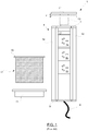
- FIGS 1 to 3 illustrate a known concealable power outlet assembly (COPA) 1.
- the COPA 1 consists of a plurality of power outlet sockets 3a, 3b, 3c, which are mounted on a frame 4 that is comprised of two vertical rails, 5a, 5b, fastened together by a header 7 and a jamb 9.
- the power outlet sockets 3a, 3b, 3c are provided with power by an electrical cable 8.
- a cover plate 11 is fastened to the header by a spring loaded catch stem 13. Pushing down on the cover plate 11 causes the stem to unlatch and telescope upwardly as indicated by arrow 2 so that the cover plate 11 pops up and may be grasped for purposes of lifting the frame 4.
- a sleeve 17 is provided that has an upper circumferential flange 19.
- the sleeve has a thread around its outside which threadedly receives a nut 21.
- a hole 10 is drilled through the bench top 23 which the sleeve 17 is then inserted through as shown so that the underside of the flange 19 rests on the top of the bench surrounding the hole.
- the frame 4 is then inserted through the sleeve 17 so that the outlying underside of the cover plate 11 rests on the flange 19 surrounding the hole 10.
- FIG. 3 shows the frame once it has been pulled up by the cover plate 11 to thereby make GPOs 3a, 3b, 3c accessible above the bench 23 for use.
- the assembly includes a column having a plug-in part including an insert for supply voltage connections.
- the plug-in part has a top end, and is partially surrounded by a circular shell.
- the plug-in part is moved from a retracted position into an extended position, and shifted into a guide that is arranged on an inner side of the circular shell.
- the shifting of the plug-in part from the retracted position to the extended position, and from the extended position to the retracted position is triggered and effected by an mechanical impact on the top end.
- a concealable power outlet assembly according to claim 1.
- CPOA concealable power outlet assembly
- Figure 7 is an assembled, partially cutaway side view of the CPOA 27 in a retracted configuration.
- the CPOA 27 is comprised of a housing 29 for mounting fast with a bench and a power outlet sub-assembly 31 that is slideably received by the housing 29.
- the housing 29 is comprised of housing tube 33, a circular baseplate 35, which is fastened to the bottom of the tube 33 and a mounting flange 37 that is fastened to the upper edge of the tube 33.
- the housing tube 33 is formed as an extrusion with longitudinal internal channels 39 that assist in the fastening of the circular baseplate at the bottom of the tube 33 and the mounting flange 37 at the top.
- the housing further includes opposed first and second elongate guides 41a and 41b which are disposed oppositely along the internal wall of the housing tube 33. An assembled view of the housing is provided in Figure 5 .
- the power outlet sub-assembly 31 which is shown in assembled view in Figure 6 , comprises first and second vertical rails 43a, 43b.
- a spacing member in the form of arcuate extrusion 45 attaches to and holds the first and second rails apart.
- the rails 43a, 43b have outer edges 42a, 42b, which respectively ride along the first and second guides 41a, 41b that are disposed along the internal wall of the housing tube 33.
- Inner edges of the rails 43a, 43b are formed as opposed elongate slots for retaining outer edges of GPO sockets 46a, 46b, 46c and blanking plate 48.
- the arcuate extrusion 45 and the first and second rails 43a. 43n are integrally formed as a single-piece slider extrusion 46.
- a semicircular base-plate 47 fastens to the bottom edge of the slider extrusion 46 for adding rigidity thereto.
- the semicircular base plate 47 is formed with an opening 49 therethrough.
- the opening 49 allows for passage of a compressed gas strut 51 therethrough and also for passage of an electrical cable 53 (shown in Figure 12 ) which provides electrical power to the GPOs 46a, 46b, 46c.
- the circular baseplate 35 is also formed with an opening 36 for passage of electrical cable 53.
- GPO general purpose outlet
- USB universal synchronous bus
- a receptacle in the form of cup 55 is fastened to the top of the slider extrusion 46.
- a disk of material of the bench may be placed in the cup 55 so that a seamless appearance is provided when the CPOA 27 is in the retracted configuration.
- the gas compression strut 51 comprises a biasing assembly which is disposed between the housing tube baseplate 35 and the cup 55. Opposed ends of the strut 51 are located into corresponding receptacles 57 and 59 formed into the housing tube baseplate 35 and the cup 55 respectfully.
- a two-part push-actuated latch 61 is disposed between the housing and the power outlet sub-assembly.
- the latch 61 is comprised of a first part 61a which is fastened to rail 43b and a second part 61b, which is fastened to the inside wall of the tubular housing 33.
- Push actuated latches are known in the prior art. They latch when the two parts are brought together and they release in response to one part being moved relative to the other in a predetermined direction.
- a tradesperson in order to install the CPOA 27 in a bench 23 a tradesperson firstly makes a hole 24 corresponding to the inner diameter of the tubular housing 33 through the bench. Depending on how the hole is cut it may produce a disk of bench material 26 which is suitable for placement in the cup 55 as shown in Figure 8 . Alternatively, the disk of bench material 26 may be produced separately, for example in the factory where the bench is manufactured.
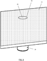
- FIG. 9 is a view of the top of the bench 23 with the CPOA 27 installed and shown in the retracted configuration. It will be observed that since the cup 55 holds a disk 26 of the bench material the overall impression of the bench top is that it is virtually seamless and the installation of the CPOA 27 makes little visual impact in the retracted configuration, which is highly desirable.
- the latch Upon pushing down on the disk of bench material 26, which is located in the cup 55, the latch releases and so the CPOA is brought to the extended configuration that is shown in Figures 10 and 11 .
- the GPOs are accessible and can receive power plugs 50a, 50b, 50c for appliances as shown in Figure 12 .
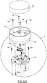
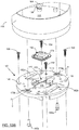
- FIG. 13 a concealable power outlet assembly (CPOA) 127 according to the present invention is shown in exploded view.
- Figures 13A , 13B and 1C show various components in more detail.
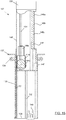
- Figure 14 is an assembled, partially cutaway side view of the CPOA 127 in a retracted configuration.
- the CPOA 127 is comprised of a housing 129 for mounting fast with a bench and a power outlet sub-assembly 131 that is slideably received by the housing 129.
- the housing 129 is comprised of housing tube 133, and a mounting flange 137 that has a collar portion that is clamped within the upper end of the tube 133 by means of screw-tightened clamp ring 134 (shown in two parts in Figure 13 ).
- a rack 151 is fastened longitudinally along the inner wall of the tube 133.
- the housing tube 133 is formed with a longitudinal slot 139 (best seen in Figure 15 ), closed at upper and lower ends that receives an outward protrusion from the power outlet sub-assembly 131 to thereby guide the assembly as it slides within the tube 133.
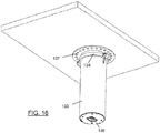
- An assembled view of the housing, shown in use, is provided in Figure 16 .
- a bottom plate 139 ( Figures 14 , 15 , 16 ) closes the lower extremity of the tube 133.
- a mains electricity power socket 148 is mounted through the bottom plate 139.
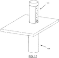
- the power outlet sub-assembly 131 which is shown extending from a benchtop in use in Figure 17 , comprises first and second vertical rails 143a, 143b. Inner edges of the rails 143a, 143b are formed as opposed elongate slots for retaining outer edges of GPO sockets 146a, 146b, 146c and USB outlet 148.
- the arcuate extrusion 145 and the first and second rails 143a 143b are integrally formed as a single-piece slider extrusion 146.
- a base-plate 147 is fastened to the bottom edge of the slider extrusion 146 for adding rigidity thereto and for supporting a powered pinion assembly 144.
- the powered pinion assembly 144 comprises an electric motor 144a, pinion 144c and bevel gear box 144b interconnecting a drive shaft of the electric motor and the pinion 144c.
- the electric motor 144a comprises one type of electrically operated actuator that may be used to move the power outlet subassembly 127 relative to the housing 129.
- one or more solenoids may be used.
- the baseplate 147 is formed with an opening therethrough that allows for passage of an electrical cable from power socket 148 (shown in Figures 14 , 15 , 16 ) which provides electrical power to the GPOs 146a, 146b, 146c and printed circuit board 142.
- a receptacle is provided in the form of cup 155 which, as will be explained in more detail shortly, is fastened over a circular cover 140 that closes the top of the slider extrusion 146.
- the cover 140 is formed with a central recess in which a load cell 160 locates.
- Printed circuit board 142 is mounted to the underside of cover 140 and electrically connected to the load cell 160 through a hole 176 formed through the central recess 170 of the cover 140.
- the printed circuit board 142 interconnects components comprising a control circuit for the motor and also a power supply circuit for converting the mains power to low voltage direct current for operation of the control circuit, the motor and the USB socket 148.
- Figure 13A and 13B are more detailed views of the cup 155, cover 140 and load cell 160 with Figure 13B being a close up of the circular region "A" indicated in Figure 13A .
- Figure 13C is a cross section view through the line B-B' of Figure 13B .
- the floor 162 of cup 155 is formed with four bosses 164 having threaded bores 168 formed into them that receive disk height adjustment screws 166 ( Fig 12A ). Accordingly, by rotating the height adjustment screws the plug 126, which rests on the heads of the screws 166 may be levelled flush with the upper edge of cup 155.
- the cover 140 is formed with a central recess 170 about which are located clips 172 for holding a base 174 of the load cell 160 in place in the recess.
- a hole 176 is formed through the bottom of the recess 170 allowing electrical terminals of the load cell 160 to be connected to the PCB 142, which is attached to the underside of the cover 140.
- the cover 140 is integrally formed with two pairs of resilient supports, being a first pair 178a, 178b and a second pair 180a, 180b.
- Each of the resilient supports comprise tongues that have one end continuous with or fastened to the cover 140 so that their remote ends which are sized to stand proud of the surrounding cover, are spring-like.
- the first pair 178a, 178b of the resilient supports are formed with holes 177a, 177b through them for the passage of cup attachment screws 180a, 180b. Points of the cup attachment screws 180a, 180b are received into threaded holes formed in the underside of the base 162 of cup 155.
- the base of the cup 155 sits upon, and is fastened to, the resilient supports 178a, 178b.
- the base also sits upon the second pair of resilient supports 182a, 182b.
- Cover 140 is fastened to the top of the slider extrusion 146 by means of screws 158 which extend through holes 159 formed through the cover into the upper ends of longitudinal channels 184 ( Fig. 13 ) formed along the inside of the arcuate extrusion 146.
- the load cell 160 causes motor 144 to operate via a control circuit of the PCB 142 that results in the motor rotating in alternate directions in response to successive applications of force from a user that change the electrical state of the load cell 160.
- a disk 126 of material of the bench may be placed in the cup 155 so that a seamless appearance is provided when the CPOA 27 is in the retracted configuration.
- a cylindrical sleeve 139 mounts into the top of flange 137 and encircles holder 155 in use in the retracted configuration shown in Figure 14 .
- Teeth of the pinion 144c extend through an opening 130 ( Figure 14 ) formed in slider extrusion 146 to mesh with the rack 151, as best seen in Figures 14 and 15 .
- a tradesperson in order to install the CPOA 127 in a bench 23 a tradesperson firstly makes a hole 24 corresponding to the inner diameter of the tubular housing 33 through the bench. Depending on how the hole is cut it may produce a disk of bench material 126 which is suitable for placement in the holder 155 as shown in Figures 14 and 15 . Alternatively, the disk of bench material 126 may be produced separately, for example in the factory where the bench is manufactured.
- the flange 137 of the housing is fastened to the underside of the bench about the hole 24 with epoxy resin as shown in Figure 16 .
- the holder tube 133, containing the power outlet sub-assembly 131 is then attached to the underside of the flange and rotated to point the GPOs 146a, 146b and 146c in a desired direction.
- the clamp 134 is then tightened to ensure that the holder tube 133 is fastened securely in place.
- Electrical power cables similar to cables 53 are connected to the premise's power supply in order to supply electricity to the GPOs 146a, 146b, 146c and also to a power supply circuit for the motor 144a.
- the flanged collar may firstly be mounted to the underside of the bench and then, once the flanged collar is securely in place, the tubular body may be clamped to the collar portion of the flanged collar at a desired orientation so that the GPO outlets face in the desired direction when the apparatus is brought to the extended configuration that is shown in Figure 15 .
- Figure 15A is a view of the top of the bench 23 with the CPOA 127 installed and shown in the retracted configuration. It will be noted that since the holder 155 holds a disk 126 of the bench material the overall impression of the bench top will be that it is virtually seamless and the installation of the CPOA 127 makes little visual impact in the retracted configuration, which is highly desirable.
- the base 162 of the holder overcomes the upward basing force of the resilient supports 178a, 178b and 182a, 182b so that the underside of the base 162 of cup 155 exerts pressure on the load cell 160 thereby causing it to change its electrical characteristics.
- the load cell 160 generates a low voltage signal that the control circuit of PCB 142 responds to by activating the motor 144a so that pinion 144c turns and, due to its engagement with rack 151, brings the CPOA 127 to the extended configuration that is shown in Figures 15 and 17 .
- the GPOs 146a, 146b, 146c are accessible as shown in Figure 17 and can receive power plugs 50a, 50b, 50c (illustrated in Figure 12 ) for benchtop appliances.
- the embodiment of the invention provides a concealable power outlet assembly for mounting under a benchtop which is an improvement to the previously described concealable power outlet assembly of the prior art since the user does not have to pull the outlets up out of the bench. Furthermore, the upper holder receives bench material that matches the surrounding bench so that in the retracted configuration the power outlet assembly makes little visual impact.
- embodiments of the invention are convenient for a user to operate since they need to merely push down upon the bench material that is mounted to the top of the power outlet assembly in order to either unlatch the gas strut or operate the electric motor to bring the assembly from its retracted configuration to its extended configuration for use. Consequently there is no need for a separate and unsightly electrical switch or push button to operate the apparatus.
- the preferred activation sensor of the preferred embodiment is a load cell Where a momentary push button switch with internal biasing of the switch button is used then the biasing supports on the cover 140 will not be necessary.
- the cover 140 is arranged to not only provide a mounting platform for both the load cell and the PCB 142 but also to provide the resilient supports 178a, 178b and 182a, 182b that bias the base 162 of the cup 155 away from the load cell so that it is only upon application of user force downwardly to the cup 155 that the biasing of the supports is overcome and the load cell is operated for alternatively causing the extension and withdrawal of the slider assembly.
Landscapes
- Engineering & Computer Science (AREA)
- Architecture (AREA)
- Civil Engineering (AREA)
- Structural Engineering (AREA)
- Connector Housings Or Holding Contact Members (AREA)
- Details Of Connecting Devices For Male And Female Coupling (AREA)
- Manipulator (AREA)
Claims (14)
- Verdeckbare Steckdosenbaugruppe (127) zur Montage an einer Bank, die Folgendes beinhaltet:ein Gehäuse (129) zur festen Montage an einer Unterseite der Bank;eine Steckdosenunterbaugruppe (131), die verschiebbar von dem Gehäuse (129) aufgenommen wird und einen oberen Abschnitt beinhaltet;einen Sensor, umfassend eine Kraftmesszelle (160), die auf Betriebskraft reagiert, die auf den oberen Abschnitt ausgeübt wird;eine Verlängerungsbaugruppe, die einen elektrischen Aktuator beinhaltet, der auf den Sensor anspricht, um die Steckdosenunterbaugruppe (131) als Reaktion auf ein Anwenden einer Betriebskraft auf den oberen Abschnitt in Bezug auf das Gehäuse (129) zu verschieben, um dadurch die Unterbaugruppe (131) in eine ausgefahrene Konfiguration oder in eine eingefahrene Konfiguration zu bringen;wobei die verdeckbare Steckdosenbaugruppe (127), durch eine Vorspannanordnung gekennzeichnet ist, die den Sensor in Abwesenheit der Betriebskraft von dem oberen Abschnitt beabstandet, wobei bei Anwendung von Betriebskraft auf den Halter (155) die Vorspannanordnung zur Betätigung des Sensors durch den oberen Abschnitt überwunden wird;eine Montageplatte, wobei die Vorspannanordnung eine Anzahl von elastischen Halterungen (178a, 178b, 182a, 182b) umfasst, die fest mit der Montageplatte verbunden sind; undwobei der obere Abschnitt einen Halter (155) zum Halten eines Abschnitts des Bankmaterials (126) bündig mit einer Oberseite der Bank (23) beinhaltet.
- Baugruppe (127) nach Anspruch 1, wobei die Montageplatte eine Aussparung (170) beinhaltet, in der der Sensor angeordnet ist.
- Baugruppe (127) nach Anspruch 2, wobei durch die Aussparung (170) ein Loch (176) gebildet ist.
- Baugruppe (127) nach Anspruch 3, wobei eine Leiterplatte (142), die eine Steuerschaltung trägt, an einer Unterseite der Montageplatte montiert ist und in elektrischer Verbindung mit dem Sensor ist.
- Baugruppe (127) nach Anspruch 4, wobei die Steckdosenunterbaugruppe (131) ein Profil (146) beinhaltet, das in dem Gehäuse (129) gleitet, und die Montageplatte auf dem Profil (146) montiert ist.
- Baugruppe (127) nach einem der Ansprüche 1 bis 5, wobei das Gehäuse (129) einen Bund mit einem Flansch und einen rohrförmigen Körper beinhaltet und wobei in der Verwendung der Flansch an die Unterseite der Bank (23) geklebt wird und der rohrförmige Körper an den Bund geklemmt wird, wodurch der rohrförmige Körper vor einem Festklemmen an den Bund auf einen gewünschten Winkel in Bezug auf den angeflanschten Bund gedreht werden kann.
- Baugruppe (127) nach einem der vorherigen Ansprüche, wobei der elektrische Aktuator einen Motor (144a) umfasst, der ein Ritzel (144c) antreibt, das eine Zahnstange (151) eingreift.
- Baugruppe (127) nach Anspruch 7, wobei der Elektromotor (144a) in der Steckdosenunterbaugruppe (131) montiert ist und die Zahnstange (151) an dem Gehäuse (129) montiert ist.
- Baugruppe (127) nach einem der vorhergehenden Ansprüche, wobei die Steckdosenunterbaugruppe (131) eine erste und eine zweite Schiene (143a, 143b) umfasst, die jeweils mit einer ersten und einer zweiten Führung zusammenwirken, die entlang von Innenwänden des Gehäuses (129) angeordnet sind.
- Baugruppe (127) nach Anspruch 9, wobei die Steckdosenunterbaugruppe (131) ferner ein Abstandselement beinhaltet, das die erste und die zweite Schiene (143a, 143b) auseinanderhält.
- Baugruppe (127) nach Anspruch 10, wobei das Abstandselement ein bogenförmiges Profil (145) umfasst
- Baugruppe (127) nach Anspruch 11, die eine Grundplatte (147) beinhaltet, die an dem bogenförmigen Profil (145) montiert ist, um diesem Steifigkeit hinzuzufügen.
- Baugruppe (127) nach Anspruch 12, wobei die Grundplatte (147) mit einer durchgehenden Öffnung für einen Durchgang von elektrischen Leitungen gebildet ist.
- Baugruppe (127) nach einem der Ansprüche 9 bis 13, wobei eine Anzahl von elektrischen Steckdosen der Steckdosenunterbaugruppe (131) zwischen gegenüberliegenden Seiten der Schienen (143a, 143b) angeordnet sind, wobei die elektrischen Steckdosen der Steckdosenunterbaugruppe (131) eines oder mehrere von einer Allzweck-Steckdose (general purpose outlet, GPO) (146a, 146b, 146c), elektrischen Buchsen, Datennetzwerk-Anschlüssen umfassen.
Applications Claiming Priority (3)
| Application Number | Priority Date | Filing Date | Title |
|---|---|---|---|
| AU2016905283A AU2016905283A0 (en) | 2016-12-20 | Improvements to power outlets for kitchen benches | |
| AU2017904209A AU2017904209A0 (en) | 2017-10-18 | Improvements to power outlets for kitchen benches | |
| PCT/AU2017/051427 WO2018112534A1 (en) | 2016-12-20 | 2017-12-20 | Improvements to power outlets for benches |
Publications (3)
| Publication Number | Publication Date |
|---|---|
| EP3558059A1 EP3558059A1 (de) | 2019-10-30 |
| EP3558059A4 EP3558059A4 (de) | 2019-10-30 |
| EP3558059B1 true EP3558059B1 (de) | 2021-02-24 |
Family
ID=62624087
Family Applications (1)
| Application Number | Title | Priority Date | Filing Date |
|---|---|---|---|
| EP17882426.4A Active EP3558059B1 (de) | 2016-12-20 | 2017-12-20 | Verbesserungen an steckdosen für bänke |
Country Status (6)
| Country | Link |
|---|---|
| US (1) | US10777985B2 (de) |
| EP (1) | EP3558059B1 (de) |
| CN (1) | CN110198648A (de) |
| AU (1) | AU2017379420B2 (de) |
| CA (1) | CA3046692A1 (de) |
| WO (1) | WO2018112534A1 (de) |
Families Citing this family (4)
| Publication number | Priority date | Publication date | Assignee | Title |
|---|---|---|---|---|
| WO2018100538A1 (en) * | 2016-12-02 | 2018-06-07 | Byrne Norman R | Low voltage dc electrical outlets |
| US12108872B2 (en) | 2019-09-06 | 2024-10-08 | Itc Incorporated | Pedestal leg assembly |
| US10918203B1 (en) * | 2019-09-06 | 2021-02-16 | Itc Incorporated | Pedestal leg assembly |
| DE112022004721T5 (de) * | 2021-09-27 | 2024-07-25 | As America, Inc. | Badezimmerwaschtischanordnung |
Family Cites Families (22)
| Publication number | Priority date | Publication date | Assignee | Title |
|---|---|---|---|---|
| US4616285A (en) * | 1984-05-14 | 1986-10-07 | Sackett Robert L | Safety and selective use switch for a power outlet |
| IL82795A0 (en) * | 1987-06-08 | 1987-12-20 | Shimon Avitan | Electric safety socket |
| DE102004002838A1 (de) * | 2004-01-20 | 2005-08-04 | Schulte-Elektrotechnik Gmbh & Co. Kg | Anschlußsäule mit Steckdosen |
| US7137850B2 (en) * | 2004-11-01 | 2006-11-21 | Ewing Carrel W | Circuit link connector |
| US20080001510A1 (en) * | 2006-07-03 | 2008-01-03 | Jack Gershfeld | Enclosure system for electronic equipment concealable in a table top |
| US7163409B1 (en) * | 2006-07-19 | 2007-01-16 | Hoolin Research Company Limited | Modular integrated socket apparatus |
| DE102007051053A1 (de) | 2006-10-19 | 2008-08-21 | Bachmann Gmbh & Co. Kg | Anschlusssäule als Einschubteil |
| CN201028578Y (zh) * | 2007-03-20 | 2008-02-27 | 宁波新海电气股份有限公司 | 一种操作力加重的点火装置 |
| US7626120B1 (en) * | 2007-05-01 | 2009-12-01 | Premier Manufacturing Group, Inc. | Pop-up power and communication outlet apparatus for use with a table, desk or similar article |
| CN101623165B (zh) * | 2008-07-08 | 2012-03-21 | 富士康(昆山)电脑接插件有限公司 | 水杯 |
| CN102074860B (zh) * | 2009-11-22 | 2013-09-18 | 慈溪市明业通讯电子有限公司 | 弹压升降式桌面插座 |
| AU2011204973A1 (en) * | 2011-07-26 | 2013-02-14 | Kolex Pty Limited | Weather resistant power outlets |
| IL217810A (en) | 2012-01-29 | 2017-03-30 | Kramer Electronics Ltd | A rising electrical socket assembly with a reduced profile |
| CN202651457U (zh) * | 2012-05-15 | 2013-01-02 | 白润华 | 电动液晶桌面插座 |
| CN103280360B (zh) * | 2013-05-03 | 2015-09-02 | 国家电网公司 | 多触点压接开关 |
| US9635931B2 (en) | 2014-05-09 | 2017-05-02 | Apple Inc. | Table with electrical ports |
| CN104482960B (zh) * | 2014-11-19 | 2017-05-24 | 上海应用技术学院 | 集位移与力测试为一体的传感器 |
| CN204394302U (zh) * | 2015-01-07 | 2015-06-17 | 佛山市顺德区美的电热电器制造有限公司 | 煎烤机 |
| CN105489428A (zh) * | 2016-02-05 | 2016-04-13 | 苏州达方电子有限公司 | 按键结构 |
| CN205565125U (zh) * | 2016-04-19 | 2016-09-07 | 南通市泽汕电器有限公司 | 气动升降桌面插座 |
| CN206059840U (zh) * | 2016-08-31 | 2017-03-29 | 宁波腾浪网络通信设备有限公司 | 桌面插座 |
| CN106930013A (zh) * | 2017-05-09 | 2017-07-07 | 佛山市翠微自动化科技有限公司 | 一种具有缓冲防护机构的缝纫机用踏脚板机构 |
-
2017
- 2017-12-20 AU AU2017379420A patent/AU2017379420B2/en active Active
- 2017-12-20 CN CN201780079312.8A patent/CN110198648A/zh active Pending
- 2017-12-20 US US16/471,385 patent/US10777985B2/en active Active
- 2017-12-20 WO PCT/AU2017/051427 patent/WO2018112534A1/en not_active Ceased
- 2017-12-20 CA CA3046692A patent/CA3046692A1/en active Pending
- 2017-12-20 EP EP17882426.4A patent/EP3558059B1/de active Active
Non-Patent Citations (1)
| Title |
|---|
| None * |
Also Published As
| Publication number | Publication date |
|---|---|
| EP3558059A1 (de) | 2019-10-30 |
| EP3558059A4 (de) | 2019-10-30 |
| US20200052474A1 (en) | 2020-02-13 |
| AU2017379420B2 (en) | 2021-12-23 |
| CN110198648A (zh) | 2019-09-03 |
| CA3046692A1 (en) | 2018-06-28 |
| AU2017379420A1 (en) | 2019-08-01 |
| WO2018112534A1 (en) | 2018-06-28 |
| US10777985B2 (en) | 2020-09-15 |
Similar Documents
| Publication | Publication Date | Title |
|---|---|---|
| EP3558059B1 (de) | Verbesserungen an steckdosen für bänke | |
| US10804739B2 (en) | Wireless power stations | |
| US9024211B2 (en) | Power and communications grommet | |
| US20140110543A1 (en) | Photovoltaic panel support system | |
| MX2011013359A (es) | Metodo y aparato para el montaje de componentes de bastidor en bastidores. | |
| CN108616182B (zh) | 一种便于稳固安装的电气设备 | |
| US11219313B2 (en) | Unified joining and levelling system for parts of furniture and furnishing items | |
| EP2093852B1 (de) | Unterputzradio | |
| CN113208317B (zh) | 包括模块化家具部件的模块化家具装置 | |
| CN107465790B (zh) | 电子设备支架 | |
| US20080258594A1 (en) | Method of attaching rail pulls to existing kitchen or bathroom cabinets having previously installed knobs or pulls | |
| EP2910144B1 (de) | Möbelbauteil | |
| KR101283477B1 (ko) | 실린더형 전자식 잠금장치용 실린더 몸체 | |
| CN208690176U (zh) | 装有附件的接触器 | |
| DK2808852T3 (en) | remote control | |
| EP3879173B1 (de) | Bausatz von mit strom betreibbaren komponenten | |
| EP3059822A1 (de) | Elektroinstallationskastenanordnung | |
| EP3037610A1 (de) | Sperrvorrichtung | |
| CN220694804U (zh) | 一种抽屉面板用装配调节机构 | |
| CN104966921B (zh) | 一种连接器及具有该连接器的电连接装置 | |
| CN101827291B (zh) | 嵌入式音箱 | |
| CN209516226U (zh) | 具有充电手柄的可伸缩电源板 | |
| CN210723700U (zh) | 一种用于电箱的横杆滑动安装结构 | |
| AU2002100097A4 (en) | Ceramic cover plate | |
| CN108626209B (zh) | 一种电磁弹性锁紧装置 |
Legal Events
| Date | Code | Title | Description |
|---|---|---|---|
| STAA | Information on the status of an ep patent application or granted ep patent |
Free format text: STATUS: THE INTERNATIONAL PUBLICATION HAS BEEN MADE |
|
| PUAI | Public reference made under article 153(3) epc to a published international application that has entered the european phase |
Free format text: ORIGINAL CODE: 0009012 |
|
| STAA | Information on the status of an ep patent application or granted ep patent |
Free format text: STATUS: REQUEST FOR EXAMINATION WAS MADE |
|
| 17P | Request for examination filed |
Effective date: 20190711 |
|
| A4 | Supplementary search report drawn up and despatched |
Effective date: 20190909 |
|
| AK | Designated contracting states |
Kind code of ref document: A1 Designated state(s): AL AT BE BG CH CY CZ DE DK EE ES FI FR GB GR HR HU IE IS IT LI LT LU LV MC MK MT NL NO PL PT RO RS SE SI SK SM TR |
|
| AX | Request for extension of the european patent |
Extension state: BA ME |
|
| DAV | Request for validation of the european patent (deleted) | ||
| DAX | Request for extension of the european patent (deleted) | ||
| GRAP | Despatch of communication of intention to grant a patent |
Free format text: ORIGINAL CODE: EPIDOSNIGR1 |
|
| STAA | Information on the status of an ep patent application or granted ep patent |
Free format text: STATUS: GRANT OF PATENT IS INTENDED |
|
| INTG | Intention to grant announced |
Effective date: 20200910 |
|
| GRAS | Grant fee paid |
Free format text: ORIGINAL CODE: EPIDOSNIGR3 |
|
| GRAA | (expected) grant |
Free format text: ORIGINAL CODE: 0009210 |
|
| STAA | Information on the status of an ep patent application or granted ep patent |
Free format text: STATUS: THE PATENT HAS BEEN GRANTED |
|
| AK | Designated contracting states |
Kind code of ref document: B1 Designated state(s): AL AT BE BG CH CY CZ DE DK EE ES FI FR GB GR HR HU IE IS IT LI LT LU LV MC MK MT NL NO PL PT RO RS SE SI SK SM TR |
|
| REG | Reference to a national code |
Ref country code: CH Ref legal event code: EP |
|
| REG | Reference to a national code |
Ref country code: DE Ref legal event code: R096 Ref document number: 602017033574 Country of ref document: DE |
|
| REG | Reference to a national code |
Ref country code: AT Ref legal event code: REF Ref document number: 1363389 Country of ref document: AT Kind code of ref document: T Effective date: 20210315 |
|
| REG | Reference to a national code |
Ref country code: IE Ref legal event code: FG4D |
|
| REG | Reference to a national code |
Ref country code: LT Ref legal event code: MG9D |
|
| REG | Reference to a national code |
Ref country code: NL Ref legal event code: MP Effective date: 20210224 |
|
| PG25 | Lapsed in a contracting state [announced via postgrant information from national office to epo] |
Ref country code: NO Free format text: LAPSE BECAUSE OF FAILURE TO SUBMIT A TRANSLATION OF THE DESCRIPTION OR TO PAY THE FEE WITHIN THE PRESCRIBED TIME-LIMIT Effective date: 20210524 Ref country code: PT Free format text: LAPSE BECAUSE OF FAILURE TO SUBMIT A TRANSLATION OF THE DESCRIPTION OR TO PAY THE FEE WITHIN THE PRESCRIBED TIME-LIMIT Effective date: 20210624 Ref country code: FI Free format text: LAPSE BECAUSE OF FAILURE TO SUBMIT A TRANSLATION OF THE DESCRIPTION OR TO PAY THE FEE WITHIN THE PRESCRIBED TIME-LIMIT Effective date: 20210224 Ref country code: HR Free format text: LAPSE BECAUSE OF FAILURE TO SUBMIT A TRANSLATION OF THE DESCRIPTION OR TO PAY THE FEE WITHIN THE PRESCRIBED TIME-LIMIT Effective date: 20210224 Ref country code: GR Free format text: LAPSE BECAUSE OF FAILURE TO SUBMIT A TRANSLATION OF THE DESCRIPTION OR TO PAY THE FEE WITHIN THE PRESCRIBED TIME-LIMIT Effective date: 20210525 Ref country code: LT Free format text: LAPSE BECAUSE OF FAILURE TO SUBMIT A TRANSLATION OF THE DESCRIPTION OR TO PAY THE FEE WITHIN THE PRESCRIBED TIME-LIMIT Effective date: 20210224 Ref country code: BG Free format text: LAPSE BECAUSE OF FAILURE TO SUBMIT A TRANSLATION OF THE DESCRIPTION OR TO PAY THE FEE WITHIN THE PRESCRIBED TIME-LIMIT Effective date: 20210524 |
|
| REG | Reference to a national code |
Ref country code: AT Ref legal event code: MK05 Ref document number: 1363389 Country of ref document: AT Kind code of ref document: T Effective date: 20210224 |
|
| PG25 | Lapsed in a contracting state [announced via postgrant information from national office to epo] |
Ref country code: SE Free format text: LAPSE BECAUSE OF FAILURE TO SUBMIT A TRANSLATION OF THE DESCRIPTION OR TO PAY THE FEE WITHIN THE PRESCRIBED TIME-LIMIT Effective date: 20210224 Ref country code: PL Free format text: LAPSE BECAUSE OF FAILURE TO SUBMIT A TRANSLATION OF THE DESCRIPTION OR TO PAY THE FEE WITHIN THE PRESCRIBED TIME-LIMIT Effective date: 20210224 Ref country code: RS Free format text: LAPSE BECAUSE OF FAILURE TO SUBMIT A TRANSLATION OF THE DESCRIPTION OR TO PAY THE FEE WITHIN THE PRESCRIBED TIME-LIMIT Effective date: 20210224 Ref country code: NL Free format text: LAPSE BECAUSE OF FAILURE TO SUBMIT A TRANSLATION OF THE DESCRIPTION OR TO PAY THE FEE WITHIN THE PRESCRIBED TIME-LIMIT Effective date: 20210224 Ref country code: LV Free format text: LAPSE BECAUSE OF FAILURE TO SUBMIT A TRANSLATION OF THE DESCRIPTION OR TO PAY THE FEE WITHIN THE PRESCRIBED TIME-LIMIT Effective date: 20210224 |
|
| PG25 | Lapsed in a contracting state [announced via postgrant information from national office to epo] |
Ref country code: IS Free format text: LAPSE BECAUSE OF FAILURE TO SUBMIT A TRANSLATION OF THE DESCRIPTION OR TO PAY THE FEE WITHIN THE PRESCRIBED TIME-LIMIT Effective date: 20210624 |
|
| PG25 | Lapsed in a contracting state [announced via postgrant information from national office to epo] |
Ref country code: CZ Free format text: LAPSE BECAUSE OF FAILURE TO SUBMIT A TRANSLATION OF THE DESCRIPTION OR TO PAY THE FEE WITHIN THE PRESCRIBED TIME-LIMIT Effective date: 20210224 Ref country code: EE Free format text: LAPSE BECAUSE OF FAILURE TO SUBMIT A TRANSLATION OF THE DESCRIPTION OR TO PAY THE FEE WITHIN THE PRESCRIBED TIME-LIMIT Effective date: 20210224 Ref country code: AT Free format text: LAPSE BECAUSE OF FAILURE TO SUBMIT A TRANSLATION OF THE DESCRIPTION OR TO PAY THE FEE WITHIN THE PRESCRIBED TIME-LIMIT Effective date: 20210224 Ref country code: SM Free format text: LAPSE BECAUSE OF FAILURE TO SUBMIT A TRANSLATION OF THE DESCRIPTION OR TO PAY THE FEE WITHIN THE PRESCRIBED TIME-LIMIT Effective date: 20210224 |
|
| REG | Reference to a national code |
Ref country code: DE Ref legal event code: R097 Ref document number: 602017033574 Country of ref document: DE |
|
| PG25 | Lapsed in a contracting state [announced via postgrant information from national office to epo] |
Ref country code: SK Free format text: LAPSE BECAUSE OF FAILURE TO SUBMIT A TRANSLATION OF THE DESCRIPTION OR TO PAY THE FEE WITHIN THE PRESCRIBED TIME-LIMIT Effective date: 20210224 Ref country code: DK Free format text: LAPSE BECAUSE OF FAILURE TO SUBMIT A TRANSLATION OF THE DESCRIPTION OR TO PAY THE FEE WITHIN THE PRESCRIBED TIME-LIMIT Effective date: 20210224 Ref country code: RO Free format text: LAPSE BECAUSE OF FAILURE TO SUBMIT A TRANSLATION OF THE DESCRIPTION OR TO PAY THE FEE WITHIN THE PRESCRIBED TIME-LIMIT Effective date: 20210224 |
|
| PLBE | No opposition filed within time limit |
Free format text: ORIGINAL CODE: 0009261 |
|
| STAA | Information on the status of an ep patent application or granted ep patent |
Free format text: STATUS: NO OPPOSITION FILED WITHIN TIME LIMIT |
|
| PG25 | Lapsed in a contracting state [announced via postgrant information from national office to epo] |
Ref country code: AL Free format text: LAPSE BECAUSE OF FAILURE TO SUBMIT A TRANSLATION OF THE DESCRIPTION OR TO PAY THE FEE WITHIN THE PRESCRIBED TIME-LIMIT Effective date: 20210224 Ref country code: ES Free format text: LAPSE BECAUSE OF FAILURE TO SUBMIT A TRANSLATION OF THE DESCRIPTION OR TO PAY THE FEE WITHIN THE PRESCRIBED TIME-LIMIT Effective date: 20210224 |
|
| 26N | No opposition filed |
Effective date: 20211125 |
|
| PG25 | Lapsed in a contracting state [announced via postgrant information from national office to epo] |
Ref country code: SI Free format text: LAPSE BECAUSE OF FAILURE TO SUBMIT A TRANSLATION OF THE DESCRIPTION OR TO PAY THE FEE WITHIN THE PRESCRIBED TIME-LIMIT Effective date: 20210224 |
|
| PG25 | Lapsed in a contracting state [announced via postgrant information from national office to epo] |
Ref country code: IT Free format text: LAPSE BECAUSE OF FAILURE TO SUBMIT A TRANSLATION OF THE DESCRIPTION OR TO PAY THE FEE WITHIN THE PRESCRIBED TIME-LIMIT Effective date: 20210224 |
|
| PG25 | Lapsed in a contracting state [announced via postgrant information from national office to epo] |
Ref country code: IS Free format text: LAPSE BECAUSE OF FAILURE TO SUBMIT A TRANSLATION OF THE DESCRIPTION OR TO PAY THE FEE WITHIN THE PRESCRIBED TIME-LIMIT Effective date: 20210624 |
|
| PG25 | Lapsed in a contracting state [announced via postgrant information from national office to epo] |
Ref country code: MC Free format text: LAPSE BECAUSE OF FAILURE TO SUBMIT A TRANSLATION OF THE DESCRIPTION OR TO PAY THE FEE WITHIN THE PRESCRIBED TIME-LIMIT Effective date: 20210224 |
|
| REG | Reference to a national code |
Ref country code: CH Ref legal event code: PL |
|
| REG | Reference to a national code |
Ref country code: BE Ref legal event code: MM Effective date: 20211231 |
|
| PG25 | Lapsed in a contracting state [announced via postgrant information from national office to epo] |
Ref country code: LU Free format text: LAPSE BECAUSE OF NON-PAYMENT OF DUE FEES Effective date: 20211220 Ref country code: IE Free format text: LAPSE BECAUSE OF NON-PAYMENT OF DUE FEES Effective date: 20211220 |
|
| PG25 | Lapsed in a contracting state [announced via postgrant information from national office to epo] |
Ref country code: BE Free format text: LAPSE BECAUSE OF NON-PAYMENT OF DUE FEES Effective date: 20211231 |
|
| PG25 | Lapsed in a contracting state [announced via postgrant information from national office to epo] |
Ref country code: LI Free format text: LAPSE BECAUSE OF NON-PAYMENT OF DUE FEES Effective date: 20211231 Ref country code: CH Free format text: LAPSE BECAUSE OF NON-PAYMENT OF DUE FEES Effective date: 20211231 |
|
| PG25 | Lapsed in a contracting state [announced via postgrant information from national office to epo] |
Ref country code: CY Free format text: LAPSE BECAUSE OF FAILURE TO SUBMIT A TRANSLATION OF THE DESCRIPTION OR TO PAY THE FEE WITHIN THE PRESCRIBED TIME-LIMIT Effective date: 20210224 |
|
| PG25 | Lapsed in a contracting state [announced via postgrant information from national office to epo] |
Ref country code: HU Free format text: LAPSE BECAUSE OF FAILURE TO SUBMIT A TRANSLATION OF THE DESCRIPTION OR TO PAY THE FEE WITHIN THE PRESCRIBED TIME-LIMIT; INVALID AB INITIO Effective date: 20171220 |
|
| PG25 | Lapsed in a contracting state [announced via postgrant information from national office to epo] |
Ref country code: MK Free format text: LAPSE BECAUSE OF FAILURE TO SUBMIT A TRANSLATION OF THE DESCRIPTION OR TO PAY THE FEE WITHIN THE PRESCRIBED TIME-LIMIT Effective date: 20210224 |
|
| PG25 | Lapsed in a contracting state [announced via postgrant information from national office to epo] |
Ref country code: TR Free format text: LAPSE BECAUSE OF FAILURE TO SUBMIT A TRANSLATION OF THE DESCRIPTION OR TO PAY THE FEE WITHIN THE PRESCRIBED TIME-LIMIT Effective date: 20210224 |
|
| PG25 | Lapsed in a contracting state [announced via postgrant information from national office to epo] |
Ref country code: MT Free format text: LAPSE BECAUSE OF FAILURE TO SUBMIT A TRANSLATION OF THE DESCRIPTION OR TO PAY THE FEE WITHIN THE PRESCRIBED TIME-LIMIT Effective date: 20210224 |
|
| PGFP | Annual fee paid to national office [announced via postgrant information from national office to epo] |
Ref country code: DE Payment date: 20251215 Year of fee payment: 9 |
|
| PGFP | Annual fee paid to national office [announced via postgrant information from national office to epo] |
Ref country code: GB Payment date: 20251209 Year of fee payment: 9 |
|
| PGFP | Annual fee paid to national office [announced via postgrant information from national office to epo] |
Ref country code: FR Payment date: 20251215 Year of fee payment: 9 |