EP3558059B1 - Improvements to power outlets for benches - Google Patents
Improvements to power outlets for benches Download PDFInfo
- Publication number
- EP3558059B1 EP3558059B1 EP17882426.4A EP17882426A EP3558059B1 EP 3558059 B1 EP3558059 B1 EP 3558059B1 EP 17882426 A EP17882426 A EP 17882426A EP 3558059 B1 EP3558059 B1 EP 3558059B1
- Authority
- EP
- European Patent Office
- Prior art keywords
- assembly
- power outlet
- bench
- housing
- sensor
- Prior art date
- Legal status (The legal status is an assumption and is not a legal conclusion. Google has not performed a legal analysis and makes no representation as to the accuracy of the status listed.)
- Active
Links
- 238000001125 extrusion Methods 0.000 claims description 17
- 239000000463 material Substances 0.000 claims description 14
- 238000009429 electrical wiring Methods 0.000 claims 1
- 238000009434 installation Methods 0.000 description 5
- RUEIBQJFGMERJD-UHFFFAOYSA-N 1,2,3,4,5-pentachloro-6-(2-chlorophenyl)benzene Chemical compound ClC1=CC=CC=C1C1=C(Cl)C(Cl)=C(Cl)C(Cl)=C1Cl RUEIBQJFGMERJD-UHFFFAOYSA-N 0.000 description 4
- 230000005611 electricity Effects 0.000 description 3
- 230000000007 visual effect Effects 0.000 description 3
- 230000006835 compression Effects 0.000 description 2
- 238000007906 compression Methods 0.000 description 2
- 230000003213 activating effect Effects 0.000 description 1
- 230000004913 activation Effects 0.000 description 1
- 230000001419 dependent effect Effects 0.000 description 1
- 238000010586 diagram Methods 0.000 description 1
- 239000003822 epoxy resin Substances 0.000 description 1
- 210000003141 lower extremity Anatomy 0.000 description 1
- 238000000034 method Methods 0.000 description 1
- 229920000647 polyepoxide Polymers 0.000 description 1
- 230000003068 static effect Effects 0.000 description 1
- 230000001360 synchronised effect Effects 0.000 description 1
- 210000002105 tongue Anatomy 0.000 description 1
- 230000001960 triggered effect Effects 0.000 description 1
Images


Classifications
-
- H—ELECTRICITY
- H02—GENERATION; CONVERSION OR DISTRIBUTION OF ELECTRIC POWER
- H02G—INSTALLATION OF ELECTRIC CABLES OR LINES, OR OF COMBINED OPTICAL AND ELECTRIC CABLES OR LINES
- H02G3/00—Installations of electric cables or lines or protective tubing therefor in or on buildings, equivalent structures or vehicles
- H02G3/02—Details
- H02G3/08—Distribution boxes; Connection or junction boxes
- H02G3/18—Distribution boxes; Connection or junction boxes providing line outlets
-
- A—HUMAN NECESSITIES
- A47—FURNITURE; DOMESTIC ARTICLES OR APPLIANCES; COFFEE MILLS; SPICE MILLS; SUCTION CLEANERS IN GENERAL
- A47B—TABLES; DESKS; OFFICE FURNITURE; CABINETS; DRAWERS; GENERAL DETAILS OF FURNITURE
- A47B21/00—Tables or desks for office equipment, e.g. typewriters, keyboards
- A47B21/06—Tables or desks for office equipment, e.g. typewriters, keyboards characterised by means for holding, fastening or concealing cables
-
- H—ELECTRICITY
- H01—ELECTRIC ELEMENTS
- H01R—ELECTRICALLY-CONDUCTIVE CONNECTIONS; STRUCTURAL ASSOCIATIONS OF A PLURALITY OF MUTUALLY-INSULATED ELECTRICAL CONNECTING ELEMENTS; COUPLING DEVICES; CURRENT COLLECTORS
- H01R25/00—Coupling parts adapted for simultaneous co-operation with two or more identical counterparts, e.g. for distributing energy to two or more circuits
- H01R25/006—Coupling parts adapted for simultaneous co-operation with two or more identical counterparts, e.g. for distributing energy to two or more circuits the coupling part being secured to apparatus or structure, e.g. duplex wall receptacle
-
- A—HUMAN NECESSITIES
- A47—FURNITURE; DOMESTIC ARTICLES OR APPLIANCES; COFFEE MILLS; SPICE MILLS; SUCTION CLEANERS IN GENERAL
- A47B—TABLES; DESKS; OFFICE FURNITURE; CABINETS; DRAWERS; GENERAL DETAILS OF FURNITURE
- A47B21/00—Tables or desks for office equipment, e.g. typewriters, keyboards
- A47B21/06—Tables or desks for office equipment, e.g. typewriters, keyboards characterised by means for holding, fastening or concealing cables
- A47B2021/066—Tables or desks for office equipment, e.g. typewriters, keyboards characterised by means for holding, fastening or concealing cables with power or communication connection interface
- A47B2021/068—Tables or desks for office equipment, e.g. typewriters, keyboards characterised by means for holding, fastening or concealing cables with power or communication connection interface with pop-up power outlet
Landscapes
- Engineering & Computer Science (AREA)
- Architecture (AREA)
- Civil Engineering (AREA)
- Structural Engineering (AREA)
- Connector Housings Or Holding Contact Members (AREA)
- Details Of Connecting Devices For Male And Female Coupling (AREA)
- Manipulator (AREA)
Description
- The present invention concerns a concealable power outlet assembly (referred to herein as a "CPOA") for a bench such as a kitchen bench.
- Any references to methods, apparatus or documents of the prior art are not to be taken as constituting any evidence or admission that they formed, or form part of the common general knowledge.
- General purpose power outlets for mounting into a bench, such as a kitchen bench are known in the prior art. For example,
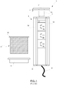
Figures 1 to 3 illustrate a known concealable power outlet assembly (COPA) 1. TheCOPA 1 consists of a plurality ofpower outlet sockets frame 4 that is comprised of two vertical rails, 5a, 5b, fastened together by aheader 7 and ajamb 9. Thepower outlet sockets electrical cable 8. Acover plate 11 is fastened to the header by a spring loadedcatch stem 13. Pushing down on thecover plate 11 causes the stem to unlatch and telescope upwardly as indicated byarrow 2 so that thecover plate 11 pops up and may be grasped for purposes of lifting theframe 4. - A
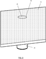
sleeve 17 is provided that has an uppercircumferential flange 19. The sleeve has a thread around its outside which threadedly receives anut 21. With reference toFigure 2 , in order to install the COPA 1 ahole 10 is drilled through thebench top 23 which thesleeve 17 is then inserted through as shown so that the underside of theflange 19 rests on the top of the bench surrounding the hole. Theframe 4 is then inserted through thesleeve 17 so that the outlying underside of thecover plate 11 rests on theflange 19 surrounding thehole 10. Thenut 21 is then tightened to cause thesleeve 17 to compress a little around theframe 4 so that the frame can be pulled up by thecover plate 11 and will remain in place once pulled up by virtue of friction between thevertical rails sleeve 17.Figure 3 shows the frame once it has been pulled up by thecover plate 11 to thereby makeGPOs bench 23 for use. When the time comes to conceal theframe 4 it is pushed back down again by applying downward force on thecover plate 11 sufficient to overcome the static friction between the sleeve and therails -
DE 10 2007 051 053 - It is an object of the present invention to provide a concealable power outlet assembly for mounting on a benchtop which is an improvement to the previously described concealable power outlet assembly of the prior art and which is convenient for a user to operate.
- According to a first embodiment of the present invention there is provided a concealable power outlet assembly according to
claim 1. - Preferred embodiments of the invention are the subject matter of the dependent claims, whose content is to be understood as forming an integral part of the present description.
- Preferred features, embodiments and variations of the invention may be discerned from the following Detailed Description which provides sufficient information for those skilled in the art to perform the invention. The Detailed Description is not to be regarded as limiting the scope of the preceding Summary of the Invention in any way. The Detailed Description will make reference to a number of drawings as follows:
- Figure 1
- illustrates various parts of a prior art concealable power outlet assembly (CPOA).
- Figure 2
- illustrates the prior art CPOA of
Figure 1 assembled and installed in a bench and shown in a retracted configuration. - Figure 3
- depicts the CPOA of
Figure 2 in an extended configuration. - Figure 4
- is an exploded view of a CPOA according to a first example not according to the present invention.
- Figure 5
- is a view of a housing of the CPOA of
Figure 4 . - Figure 6
- is a view of a power outlet sub-assembly of the CPOA of
Figure 4 . - Figure 7
- is an assembled, partially cutaway side view of the CPOA of
Figure 4 in a retracted configuration. - Figure 7A
- shows a bench that has been prepared for installation of the CPOA of
Figure 4 . - Figure 8
- shows the CPOA of
Figure 7 installed to the bench. - Figure 9
- is a view of the bench top with the CPOA installed and in the retracted configuration.
- Figure 10
- is a side view of the CPOA of
Figures 8 and9 in an extended configuration. - Figure 11
- is a view of the bench top showing the CPOA of
Figures 8 and9 in the extended configuration. - Figure 12
- shows the CPOA of
Figure 8 and9 in the extended configuration in use with a number of power plugs connected thereto. - Figure 13
- is an exploded view of a CPOA according to an embodiment of the invention.
- Figure 13A
- is a detail view of a portion of the exploded view of
Figure 13 . - Figure 13B
- is an enlarged view of a circled region of
Figure 13A . - Figure 13C
- is a cross sectional view through an upper part of the power outlet sub-assembly of
Figure 13 . - Figure 14
- is a partial cross-sectional view of the CPOA of
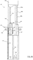
Figure 13 in a retracted configuration. - Figure 15
- corresponds to
Figure 14 with the CPOA in an extended configuration. - Figure 15A
- shows the CPOA of
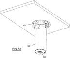
Figure 13 installed to the bench. - Figure 16
- is an underside view of the installed CPOA of
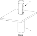
Figure 15A . - Figure 17
- Is a view of the bench top showing the CPOA of
Figures 15A and16 in the extended configuration. - Figure 18
- Is a diagram showing how the disk of material of the CPOA of the preferred embodiment of the invention may be removed from to make a hole through a bench for mounting of the CPOA.
- Referring now to
Figure 4 a concealable power outlet assembly (CPOA) 27 according to an example not according to the present invention is shown in exploded view. -
Figure 7 is an assembled, partially cutaway side view of theCPOA 27 in a retracted configuration. - Broadly speaking, the
CPOA 27 is comprised of ahousing 29 for mounting fast with a bench and apower outlet sub-assembly 31 that is slideably received by thehousing 29. - The
housing 29 is comprised ofhousing tube 33, acircular baseplate 35, which is fastened to the bottom of thetube 33 and a mountingflange 37 that is fastened to the upper edge of thetube 33. Thehousing tube 33 is formed as an extrusion with longitudinalinternal channels 39 that assist in the fastening of the circular baseplate at the bottom of thetube 33 and the mountingflange 37 at the top. The housing further includes opposed first and secondelongate guides housing tube 33. An assembled view of the housing is provided inFigure 5 . - Returning again to
Figure 4 , thepower outlet sub-assembly 31, which is shown in assembled view inFigure 6 , comprises first and secondvertical rails arcuate extrusion 45 attaches to and holds the first and second rails apart. Therails outer edges second guides housing tube 33. Inner edges of therails GPO sockets plate 48. In the presently described example thearcuate extrusion 45 and the first andsecond rails 43a. 43n are integrally formed as a single-piece slider extrusion 46. - A semicircular base-
plate 47 fastens to the bottom edge of theslider extrusion 46 for adding rigidity thereto. Thesemicircular base plate 47 is formed with anopening 49 therethrough. As will be seen, theopening 49 allows for passage of acompressed gas strut 51 therethrough and also for passage of an electrical cable 53 (shown inFigure 12 ) which provides electrical power to theGPOs circular baseplate 35 is also formed with anopening 36 for passage ofelectrical cable 53. - While only GPOs are present in the presently described example other types of the electrical outlets may be used. Indeed any or more of general purpose outlet (GPO) electrical sockets, data network ports such as Ethernet ports and universal synchronous bus (USB) power outlets may be incorporated, for example.
- A receptacle in the form of
cup 55 is fastened to the top of theslider extrusion 46. As will be explained during installation of the CPOA 27 a disk of material of the bench may be placed in thecup 55 so that a seamless appearance is provided when theCPOA 27 is in the retracted configuration. - The
gas compression strut 51 comprises a biasing assembly which is disposed between thehousing tube baseplate 35 and thecup 55. Opposed ends of thestrut 51 are located intocorresponding receptacles housing tube baseplate 35 and thecup 55 respectfully. - As best seen in
Figure 7 , a two-part push-actuatedlatch 61 is disposed between the housing and the power outlet sub-assembly. Thelatch 61 is comprised of afirst part 61a which is fastened torail 43b and asecond part 61b, which is fastened to the inside wall of thetubular housing 33. Push actuated latches are known in the prior art. They latch when the two parts are brought together and they release in response to one part being moved relative to the other in a predetermined direction. In the retracted configuration, as shown inFigures 7 ,8 ,9 , wherein thepower outlet subassembly 31 is withdrawn down into the housing and latched in place, exerting downward force upon the power outlet sub-assembly causes thefirst part 61a of thelatch 61 to move downward relative to thesecond part 61b so that they unlatch. - Once unlatched the
compression strut 51 is free to extend thereby forcing the sub-assembly 31 to slide up and away from thehousing 29 to thereby bring the power outlet sub-assembly to extend above thebench 23 for use as shown inFigures 10 and11 . - With reference to
Figure 7A , in order to install theCPOA 27 in a bench 23 a tradesperson firstly makes ahole 24 corresponding to the inner diameter of thetubular housing 33 through the bench. Depending on how the hole is cut it may produce a disk ofbench material 26 which is suitable for placement in thecup 55 as shown inFigure 8 . Alternatively, the disk ofbench material 26 may be produced separately, for example in the factory where the bench is manufactured. - The
flange 37 of the housing is fastened to the underside of the bench about thehole 24 as shown inFigure 8 . Electrical power cable 53 (visible inFigure 12 ) is connected to the premise's power supply in order to supply electricity to theGPOs Figure 9 is a view of the top of thebench 23 with theCPOA 27 installed and shown in the retracted configuration. It will be observed that since thecup 55 holds adisk 26 of the bench material the overall impression of the bench top is that it is virtually seamless and the installation of theCPOA 27 makes little visual impact in the retracted configuration, which is highly desirable. - Upon pushing down on the disk of
bench material 26, which is located in thecup 55, the latch releases and so the CPOA is brought to the extended configuration that is shown inFigures 10 and11 . In the extended configuration the GPOs are accessible and can receivepower plugs Figure 12 . - When it is time to return to the retracted configuration the power plugs 50a, 50b, 50c are removed and downward force is then applied to the
disk 26 and hence thecup 55 that is sufficient to overcome thegas strut 51 and so push thepower outlet sub-assembly 31 back into thehousing 27 until the twoparts latch 61 catch each other. - Referring now to
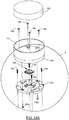
Figure 13 a concealable power outlet assembly (CPOA) 127 according to the present invention is shown in exploded view.Figures 13A ,13B and1C show various components in more detail.Figure 14 is an assembled, partially cutaway side view of theCPOA 127 in a retracted configuration. - Broadly speaking, the
CPOA 127 is comprised of ahousing 129 for mounting fast with a bench and apower outlet sub-assembly 131 that is slideably received by thehousing 129. - The
housing 129 is comprised ofhousing tube 133, and a mountingflange 137 that has a collar portion that is clamped within the upper end of thetube 133 by means of screw-tightened clamp ring 134 (shown in two parts inFigure 13 ). Arack 151 is fastened longitudinally along the inner wall of thetube 133. Thehousing tube 133 is formed with a longitudinal slot 139 (best seen inFigure 15 ), closed at upper and lower ends that receives an outward protrusion from thepower outlet sub-assembly 131 to thereby guide the assembly as it slides within thetube 133. An assembled view of the housing, shown in use, is provided inFigure 16 . A bottom plate 139 (Figures 14 ,15 ,16 ) closes the lower extremity of thetube 133. A mainselectricity power socket 148 is mounted through the bottom plate 139. - Returning again to
Figure 13 , thepower outlet sub-assembly 131, which is shown extending from a benchtop in use inFigure 17 , comprises first and secondvertical rails rails GPO sockets USB outlet 148. In the invention thearcuate extrusion 145 and the first andsecond rails 143a 143b are integrally formed as a single-piece slider extrusion 146. - A base-
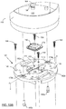
plate 147 is fastened to the bottom edge of theslider extrusion 146 for adding rigidity thereto and for supporting apowered pinion assembly 144. Thepowered pinion assembly 144 comprises anelectric motor 144a,pinion 144c andbevel gear box 144b interconnecting a drive shaft of the electric motor and thepinion 144c. Theelectric motor 144a comprises one type of electrically operated actuator that may be used to move thepower outlet subassembly 127 relative to thehousing 129. For example in other embodiments of the invention one or more solenoids may be used. Thebaseplate 147 is formed with an opening therethrough that allows for passage of an electrical cable from power socket 148 (shown inFigures 14 ,15 ,16 ) which provides electrical power to theGPOs circuit board 142. - A receptacle is provided in the form of
cup 155 which, as will be explained in more detail shortly, is fastened over acircular cover 140 that closes the top of theslider extrusion 146. Thecover 140 is formed with a central recess in which aload cell 160 locates. Printedcircuit board 142 is mounted to the underside ofcover 140 and electrically connected to theload cell 160 through ahole 176 formed through thecentral recess 170 of thecover 140. The printedcircuit board 142 interconnects components comprising a control circuit for the motor and also a power supply circuit for converting the mains power to low voltage direct current for operation of the control circuit, the motor and theUSB socket 148. -
Figure 13A and13B are more detailed views of thecup 155,cover 140 andload cell 160 withFigure 13B being a close up of the circular region "A" indicated inFigure 13A .Figure 13C is a cross section view through the line B-B' ofFigure 13B . - Referring now to
Figure 13B , thefloor 162 ofcup 155 is formed with fourbosses 164 having threadedbores 168 formed into them that receive disk height adjustment screws 166 (Fig 12A ). Accordingly, by rotating the height adjustment screws theplug 126, which rests on the heads of thescrews 166 may be levelled flush with the upper edge ofcup 155. Thecover 140 is formed with acentral recess 170 about which are locatedclips 172 for holding abase 174 of theload cell 160 in place in the recess. Ahole 176 is formed through the bottom of therecess 170 allowing electrical terminals of theload cell 160 to be connected to thePCB 142, which is attached to the underside of thecover 140. - It is important that relative movement be possible between the underside of the base of
cup 155 and the top of the load cell so that downward force on the top side of thedisk 126 can force the underside of the base 162 downward on theload cell 160 to thereby change the load cell's electrical state. In order to allow for the relative movement thecover 140 is integrally formed with two pairs of resilient supports, being afirst pair second pair cover 140 so that their remote ends which are sized to stand proud of the surrounding cover, are spring-like. Thefirst pair holes 177a, 177b through them for the passage ofcup attachment screws cup attachment screws base 162 ofcup 155. - Accordingly, the base of the
cup 155 sits upon, and is fastened to, theresilient supports resilient supports - Cover 140 is fastened to the top of the
slider extrusion 146 by means ofscrews 158 which extend throughholes 159 formed through the cover into the upper ends of longitudinal channels 184 (Fig. 13 ) formed along the inside of thearcuate extrusion 146. Theload cell 160 causes motor 144 to operate via a control circuit of thePCB 142 that results in the motor rotating in alternate directions in response to successive applications of force from a user that change the electrical state of theload cell 160. During installation of the CPOA 127 adisk 126 of material of the bench may be placed in thecup 155 so that a seamless appearance is provided when theCPOA 27 is in the retracted configuration. A cylindrical sleeve 139 mounts into the top offlange 137 and encirclesholder 155 in use in the retracted configuration shown inFigure 14 . - Teeth of the
pinion 144c extend through an opening 130 (Figure 14 ) formed inslider extrusion 146 to mesh with therack 151, as best seen inFigures 14 and15 . - With reference to
Figure 18 , in order to install theCPOA 127 in a bench 23 a tradesperson firstly makes ahole 24 corresponding to the inner diameter of thetubular housing 33 through the bench. Depending on how the hole is cut it may produce a disk ofbench material 126 which is suitable for placement in theholder 155 as shown inFigures 14 and15 . Alternatively, the disk ofbench material 126 may be produced separately, for example in the factory where the bench is manufactured. - The
flange 137 of the housing is fastened to the underside of the bench about thehole 24 with epoxy resin as shown inFigure 16 . Theholder tube 133, containing thepower outlet sub-assembly 131 is then attached to the underside of the flange and rotated to point the GPOs 146a, 146b and 146c in a desired direction. Theclamp 134 is then tightened to ensure that theholder tube 133 is fastened securely in place. Electrical power cables similar to cables 53 (visible inFigure 12 ) are connected to the premise's power supply in order to supply electricity to theGPOs motor 144a. It will be realized that by making thehousing 129 in two parts, i.e. with a separate flanged collar and tubular body, the flanged collar may firstly be mounted to the underside of the bench and then, once the flanged collar is securely in place, the tubular body may be clamped to the collar portion of the flanged collar at a desired orientation so that the GPO outlets face in the desired direction when the apparatus is brought to the extended configuration that is shown inFigure 15 . -
Figure 15A is a view of the top of thebench 23 with theCPOA 127 installed and shown in the retracted configuration. It will be noted that since theholder 155 holds adisk 126 of the bench material the overall impression of the bench top will be that it is virtually seamless and the installation of theCPOA 127 makes little visual impact in the retracted configuration, which is highly desirable. - Upon pushing down on the disk of
bench material 126, which is located in theholder 155, thebase 162 of the holder overcomes the upward basing force of theresilient supports base 162 ofcup 155 exerts pressure on theload cell 160 thereby causing it to change its electrical characteristics. Theload cell 160 generates a low voltage signal that the control circuit ofPCB 142 responds to by activating themotor 144a so thatpinion 144c turns and, due to its engagement withrack 151, brings theCPOA 127 to the extended configuration that is shown inFigures 15 and17 . In the extended configuration the GPOs 146a, 146b, 146c are accessible as shown inFigure 17 and can receivepower plugs Figure 12 ) for benchtop appliances. - When it is time to return to the retracted configuration the power plugs 50a, 50b, 50c are removed and downward force is then applied to the
disk 126 so thatload cell 160 is again activated to thereby operate themotor 144a and thepinion 144c in an alternate direction to thereby bring theCPOA 127 to the retracted configuration illustrated inFigure 14 . - It will be realized that the embodiment of the invention provides a concealable power outlet assembly for mounting under a benchtop which is an improvement to the previously described concealable power outlet assembly of the prior art since the user does not have to pull the outlets up out of the bench. Furthermore, the upper holder receives bench material that matches the surrounding bench so that in the retracted configuration the power outlet assembly makes little visual impact. In addition, embodiments of the invention are convenient for a user to operate since they need to merely push down upon the bench material that is mounted to the top of the power outlet assembly in order to either unlatch the gas strut or operate the electric motor to bring the assembly from its retracted configuration to its extended configuration for use. Consequently there is no need for a separate and unsightly electrical switch or push button to operate the apparatus.
- The preferred activation sensor of the preferred embodiment, illustrated in
Figure 13 , is a load cell Where a momentary push button switch with internal biasing of the switch button is used then the biasing supports on thecover 140 will not be necessary. - It will be realized that by locating the load cell in a recess formed on one side of the cover with the PCB mounted on the underside of the cover a compact arrangement is provided for sensing user operation force directly on the
disk 126 that is held in thecup 155. Thecover 140 is arranged to not only provide a mounting platform for both the load cell and thePCB 142 but also to provide theresilient supports base 162 of thecup 155 away from the load cell so that it is only upon application of user force downwardly to thecup 155 that the biasing of the supports is overcome and the load cell is operated for alternatively causing the extension and withdrawal of the slider assembly. - Throughout the description and claims of this specification, the singular encompasses the plural unless the context otherwise requires. In particular, where the indefinite article is used, the specification is to be understood as contemplating plurality as well as singularity, unless the context requires otherwise.
- Throughout the specification and claims (if present), unless the context requires otherwise, the term "substantially" or "about" will be understood to not be limited to the value for the range qualified by the terms.
Claims (14)
- A concealable power outlet assembly (127) for bench mounting including:a housing (129) for mounting fast with an underside of the bench;a power outlet sub-assembly (131) slideably received by the housing (129) and including an upper portion;a sensor comprising a load cell (160) responsive to operative force applied to the upper portion;an extension assembly including an electric actuator responsive to the sensor for sliding the power outlet sub-assembly (131) relative to the housing (129) in response to application of operative force to the upper portion to thereby bring said sub-assembly (131) to an extended configuration or to a retracted configuration;the concealable power outlet assembly (127) characterized by a biasing arrangement spacing the sensor from the upper portion in the absence of the operative force wherein upon application of operative force to the holder (155) the biasing arrangement is overcome for operation of the sensor by the upper portion;a mounting plate wherein the biasing arrangement comprises a number of resilient supports (178a, 178b, 182a, 182b) fast with the mounting plate; andwherein the upper portion includes a holder (155) for supporting a portion of bench material (126) flush with an upper side of the bench (23).
- An assembly (127) according to claim 1, wherein the mounting plate includes a recess (170) in which the sensor is located.
- An assembly (127) according to claim 2, wherein a hole (176) is formed through the recess (170).
- An assembly (127) according to claim 3, wherein a printed circuit board (142) bearing a control circuit is mounted to an underside of the mounting plate and in electrical communication with the sensor.
- An assembly (127) according to claim 4, wherein the power outlet sub-assembly (131) includes an extrusion (146) that slides within the housing (129) and the mounting plate is mounted atop the extrusion (146).
- An assembly (127) according to any one of claims 1 to 5, wherein the housing (129) includes a collar with a flange and a tubular body and wherein in use the flange is adhered to the underside of the bench (23) and the tubular body is clamped to the collar whereby the tubular body is rotatable to a desired angle relative to the flanged collar prior to clamping thereto.
- An assembly (127) according to any one of the preceding claims, wherein the electric actuator comprises a motor (144a) that drives a pinion (144c) that meshes with a rack (151).
- An assembly (127) according to claim 7, wherein the electric motor (144a) is mounted in the power outlet sub assembly (131) and the rack (151) is mounted to the housing (129).
- An assembly (127) according to any one of the preceding claims, wherein the power outlet sub-assembly (131) comprises first and second rails (143a, 143b) that respectively cooperate with first and second guides disposed along internal walls of the housing (129).
- An assembly (127) according to claim 9, wherein the power outlet sub-assembly (131) further includes a spacing member that holds the first and second rails apart (143a, 143b).
- An assembly (127) according to claim 10, wherein the spacing member comprises an arcuate extrusion (145).
- An assembly (127) according to claim 11, including a base-plate (147) mounted to the arcuate extrusion (145) for adding rigidity thereto.
- An assembly (127) according to claim 12, wherein the base plate (147) is formed with an opening therethrough for passage of electrical wiring.
- An assembly (127) according to any one of claims 9 to 13 wherein a number of electrical outlets of the power outlet sub-assembly (131) are disposed between opposed sides of the rails (143a, 143b), wherein the electrical outlets of the power outlet sub-assembly (131) comprise one or more of a general purpose outlet (GPO) (146a, 146b, 146c); electrical sockets; data network ports.
Applications Claiming Priority (3)
| Application Number | Priority Date | Filing Date | Title |
|---|---|---|---|
| AU2016905283A AU2016905283A0 (en) | 2016-12-20 | Improvements to power outlets for kitchen benches | |
| AU2017904209A AU2017904209A0 (en) | 2017-10-18 | Improvements to power outlets for kitchen benches | |
| PCT/AU2017/051427 WO2018112534A1 (en) | 2016-12-20 | 2017-12-20 | Improvements to power outlets for benches |
Publications (3)
| Publication Number | Publication Date |
|---|---|
| EP3558059A1 EP3558059A1 (en) | 2019-10-30 |
| EP3558059A4 EP3558059A4 (en) | 2019-10-30 |
| EP3558059B1 true EP3558059B1 (en) | 2021-02-24 |
Family
ID=62624087
Family Applications (1)
| Application Number | Title | Priority Date | Filing Date |
|---|---|---|---|
| EP17882426.4A Active EP3558059B1 (en) | 2016-12-20 | 2017-12-20 | Improvements to power outlets for benches |
Country Status (6)
| Country | Link |
|---|---|
| US (1) | US10777985B2 (en) |
| EP (1) | EP3558059B1 (en) |
| CN (1) | CN110198648A (en) |
| AU (1) | AU2017379420B2 (en) |
| CA (1) | CA3046692A1 (en) |
| WO (1) | WO2018112534A1 (en) |
Families Citing this family (2)
| Publication number | Priority date | Publication date | Assignee | Title |
|---|---|---|---|---|
| MX2019006312A (en) * | 2016-12-02 | 2019-07-12 | R Byrne Norman | Low voltage dc electrical outlets. |
| US10918203B1 (en) * | 2019-09-06 | 2021-02-16 | Itc Incorporated | Pedestal leg assembly |
Family Cites Families (22)
| Publication number | Priority date | Publication date | Assignee | Title |
|---|---|---|---|---|
| US4616285A (en) * | 1984-05-14 | 1986-10-07 | Sackett Robert L | Safety and selective use switch for a power outlet |
| IL82795A0 (en) * | 1987-06-08 | 1987-12-20 | Shimon Avitan | Electric safety socket |
| DE102004002838A1 (en) * | 2004-01-20 | 2005-08-04 | Schulte-Elektrotechnik Gmbh & Co. Kg | Table mounted module has multiple electrical power sockets and a docking station for a data communication plug |
| US7137850B2 (en) * | 2004-11-01 | 2006-11-21 | Ewing Carrel W | Circuit link connector |
| US20080001510A1 (en) * | 2006-07-03 | 2008-01-03 | Jack Gershfeld | Enclosure system for electronic equipment concealable in a table top |
| US7163409B1 (en) | 2006-07-19 | 2007-01-16 | Hoolin Research Company Limited | Modular integrated socket apparatus |
| DE102007051053A1 (en) * | 2006-10-19 | 2008-08-21 | Bachmann Gmbh & Co. Kg | Connection column, has plug-in part, where shifting of plug-in part from retracted position to extended position, and from extended position to retracted position is triggered and effected by mechanical impact on top end of plug-in part |
| CN201028578Y (en) * | 2007-03-20 | 2008-02-27 | 宁波新海电气股份有限公司 | Ignition device with reinforced operating force |
| US7626120B1 (en) * | 2007-05-01 | 2009-12-01 | Premier Manufacturing Group, Inc. | Pop-up power and communication outlet apparatus for use with a table, desk or similar article |
| CN101623165B (en) * | 2008-07-08 | 2012-03-21 | 富士康(昆山)电脑接插件有限公司 | Cup |
| CN102074860B (en) * | 2009-11-22 | 2013-09-18 | 慈溪市明业通讯电子有限公司 | Spring lift type desktop socket |
| AU2011204973A1 (en) * | 2011-07-26 | 2013-02-14 | Kolex Pty Limited | Weather resistant power outlets |
| IL217810A (en) | 2012-01-29 | 2017-03-30 | Kramer Electronics Ltd | Reduced profile pop-up electrical receptacle assembly |
| CN202651457U (en) * | 2012-05-15 | 2013-01-02 | 白润华 | Electric liquid crystal desktop socket |
| CN103280360B (en) * | 2013-05-03 | 2015-09-02 | 国家电网公司 | Multi-contact pressure connection switch |
| US9635931B2 (en) * | 2014-05-09 | 2017-05-02 | Apple Inc. | Table with electrical ports |
| CN104482960B (en) * | 2014-11-19 | 2017-05-24 | 上海应用技术学院 | Displacement and force test integrated sensor |
| CN204394302U (en) * | 2015-01-07 | 2015-06-17 | 佛山市顺德区美的电热电器制造有限公司 | Decoct roasting machine |
| CN105489428A (en) * | 2016-02-05 | 2016-04-13 | 苏州达方电子有限公司 | Key structure |
| CN205565125U (en) * | 2016-04-19 | 2016-09-07 | 南通市泽汕电器有限公司 | Pneumatic lift desktop socket |
| CN206059840U (en) * | 2016-08-31 | 2017-03-29 | 宁波腾浪网络通信设备有限公司 | Desktop socket |
| CN106930013A (en) * | 2017-05-09 | 2017-07-07 | 佛山市翠微自动化科技有限公司 | A kind of use in sewing machine foot pedal mechanism with buffer protection mechanism |
-
2017
- 2017-12-20 WO PCT/AU2017/051427 patent/WO2018112534A1/en active Search and Examination
- 2017-12-20 CN CN201780079312.8A patent/CN110198648A/en active Pending
- 2017-12-20 US US16/471,385 patent/US10777985B2/en active Active
- 2017-12-20 AU AU2017379420A patent/AU2017379420B2/en active Active
- 2017-12-20 CA CA3046692A patent/CA3046692A1/en active Pending
- 2017-12-20 EP EP17882426.4A patent/EP3558059B1/en active Active
Non-Patent Citations (1)
| Title |
|---|
| None * |
Also Published As
| Publication number | Publication date |
|---|---|
| US20200052474A1 (en) | 2020-02-13 |
| CA3046692A1 (en) | 2018-06-28 |
| AU2017379420A1 (en) | 2019-08-01 |
| US10777985B2 (en) | 2020-09-15 |
| EP3558059A1 (en) | 2019-10-30 |
| AU2017379420B2 (en) | 2021-12-23 |
| WO2018112534A1 (en) | 2018-06-28 |
| EP3558059A4 (en) | 2019-10-30 |
| CN110198648A (en) | 2019-09-03 |
Similar Documents
| Publication | Publication Date | Title |
|---|---|---|
| EP3558059B1 (en) | Improvements to power outlets for benches | |
| US10804739B2 (en) | Wireless power stations | |
| US6279754B1 (en) | Method and apparatus for releasably securing a computer system component within a housing | |
| MX2011013359A (en) | Method and apparatus for mounting rack components on racks. | |
| US20200359792A1 (en) | Unified joining and levelling system for parts of furniture and furnishing items | |
| EP2093852B1 (en) | Built-in radio | |
| WO2004088805A3 (en) | Frame member for a switchgear cabinet frame | |
| KR20150120120A (en) | Rotary knob assembly capable of moving up and down | |
| CN107465790B (en) | Electronic equipment support | |
| US7936242B2 (en) | Magnetically operated electrical switch | |
| US9252534B2 (en) | Swing mount for terminal blocks | |
| CN116207430A (en) | Electronic equipment | |
| KR20180118722A (en) | Modular furniture arrangement comprising electrically and mechanically connectable module furniture parts | |
| KR101283477B1 (en) | Cylinder Body for Cylindrical Electronic Lock | |
| EP2910144A1 (en) | Lighted drawer, lighting device and current collector | |
| CN114336361A (en) | Modular assembly type low-voltage switch cabinet and assembly method | |
| JPS6185730A (en) | Remote slave operating tool for electric appliance | |
| EP3059822A1 (en) | Electrical installation box assembly | |
| DK2808852T3 (en) | remote control | |
| CN211933832U (en) | Assembly for fixing rod piece | |
| CN220694804U (en) | Assembly adjusting mechanism for drawer panel | |
| CN104966921B (en) | A kind of connector and the arrangements of electric connection with the connector | |
| CN220190177U (en) | Electric pre-buried box | |
| EP3503309A1 (en) | Electric/electronic installation device | |
| CN204270940U (en) | The button that tape light energy side controls |
Legal Events
| Date | Code | Title | Description |
|---|---|---|---|
| STAA | Information on the status of an ep patent application or granted ep patent |
Free format text: STATUS: THE INTERNATIONAL PUBLICATION HAS BEEN MADE |
|
| PUAI | Public reference made under article 153(3) epc to a published international application that has entered the european phase |
Free format text: ORIGINAL CODE: 0009012 |
|
| STAA | Information on the status of an ep patent application or granted ep patent |
Free format text: STATUS: REQUEST FOR EXAMINATION WAS MADE |
|
| 17P | Request for examination filed |
Effective date: 20190711 |
|
| A4 | Supplementary search report drawn up and despatched |
Effective date: 20190909 |
|
| AK | Designated contracting states |
Kind code of ref document: A1 Designated state(s): AL AT BE BG CH CY CZ DE DK EE ES FI FR GB GR HR HU IE IS IT LI LT LU LV MC MK MT NL NO PL PT RO RS SE SI SK SM TR |
|
| AX | Request for extension of the european patent |
Extension state: BA ME |
|
| DAV | Request for validation of the european patent (deleted) | ||
| DAX | Request for extension of the european patent (deleted) | ||
| GRAP | Despatch of communication of intention to grant a patent |
Free format text: ORIGINAL CODE: EPIDOSNIGR1 |
|
| STAA | Information on the status of an ep patent application or granted ep patent |
Free format text: STATUS: GRANT OF PATENT IS INTENDED |
|
| INTG | Intention to grant announced |
Effective date: 20200910 |
|
| GRAS | Grant fee paid |
Free format text: ORIGINAL CODE: EPIDOSNIGR3 |
|
| GRAA | (expected) grant |
Free format text: ORIGINAL CODE: 0009210 |
|
| STAA | Information on the status of an ep patent application or granted ep patent |
Free format text: STATUS: THE PATENT HAS BEEN GRANTED |
|
| AK | Designated contracting states |
Kind code of ref document: B1 Designated state(s): AL AT BE BG CH CY CZ DE DK EE ES FI FR GB GR HR HU IE IS IT LI LT LU LV MC MK MT NL NO PL PT RO RS SE SI SK SM TR |
|
| REG | Reference to a national code |
Ref country code: CH Ref legal event code: EP |
|
| REG | Reference to a national code |
Ref country code: DE Ref legal event code: R096 Ref document number: 602017033574 Country of ref document: DE |
|
| REG | Reference to a national code |
Ref country code: AT Ref legal event code: REF Ref document number: 1363389 Country of ref document: AT Kind code of ref document: T Effective date: 20210315 |
|
| REG | Reference to a national code |
Ref country code: IE Ref legal event code: FG4D |
|
| REG | Reference to a national code |
Ref country code: LT Ref legal event code: MG9D |
|
| REG | Reference to a national code |
Ref country code: NL Ref legal event code: MP Effective date: 20210224 |
|
| PG25 | Lapsed in a contracting state [announced via postgrant information from national office to epo] |
Ref country code: NO Free format text: LAPSE BECAUSE OF FAILURE TO SUBMIT A TRANSLATION OF THE DESCRIPTION OR TO PAY THE FEE WITHIN THE PRESCRIBED TIME-LIMIT Effective date: 20210524 Ref country code: PT Free format text: LAPSE BECAUSE OF FAILURE TO SUBMIT A TRANSLATION OF THE DESCRIPTION OR TO PAY THE FEE WITHIN THE PRESCRIBED TIME-LIMIT Effective date: 20210624 Ref country code: FI Free format text: LAPSE BECAUSE OF FAILURE TO SUBMIT A TRANSLATION OF THE DESCRIPTION OR TO PAY THE FEE WITHIN THE PRESCRIBED TIME-LIMIT Effective date: 20210224 Ref country code: HR Free format text: LAPSE BECAUSE OF FAILURE TO SUBMIT A TRANSLATION OF THE DESCRIPTION OR TO PAY THE FEE WITHIN THE PRESCRIBED TIME-LIMIT Effective date: 20210224 Ref country code: GR Free format text: LAPSE BECAUSE OF FAILURE TO SUBMIT A TRANSLATION OF THE DESCRIPTION OR TO PAY THE FEE WITHIN THE PRESCRIBED TIME-LIMIT Effective date: 20210525 Ref country code: LT Free format text: LAPSE BECAUSE OF FAILURE TO SUBMIT A TRANSLATION OF THE DESCRIPTION OR TO PAY THE FEE WITHIN THE PRESCRIBED TIME-LIMIT Effective date: 20210224 Ref country code: BG Free format text: LAPSE BECAUSE OF FAILURE TO SUBMIT A TRANSLATION OF THE DESCRIPTION OR TO PAY THE FEE WITHIN THE PRESCRIBED TIME-LIMIT Effective date: 20210524 |
|
| REG | Reference to a national code |
Ref country code: AT Ref legal event code: MK05 Ref document number: 1363389 Country of ref document: AT Kind code of ref document: T Effective date: 20210224 |
|
| PG25 | Lapsed in a contracting state [announced via postgrant information from national office to epo] |
Ref country code: SE Free format text: LAPSE BECAUSE OF FAILURE TO SUBMIT A TRANSLATION OF THE DESCRIPTION OR TO PAY THE FEE WITHIN THE PRESCRIBED TIME-LIMIT Effective date: 20210224 Ref country code: PL Free format text: LAPSE BECAUSE OF FAILURE TO SUBMIT A TRANSLATION OF THE DESCRIPTION OR TO PAY THE FEE WITHIN THE PRESCRIBED TIME-LIMIT Effective date: 20210224 Ref country code: RS Free format text: LAPSE BECAUSE OF FAILURE TO SUBMIT A TRANSLATION OF THE DESCRIPTION OR TO PAY THE FEE WITHIN THE PRESCRIBED TIME-LIMIT Effective date: 20210224 Ref country code: NL Free format text: LAPSE BECAUSE OF FAILURE TO SUBMIT A TRANSLATION OF THE DESCRIPTION OR TO PAY THE FEE WITHIN THE PRESCRIBED TIME-LIMIT Effective date: 20210224 Ref country code: LV Free format text: LAPSE BECAUSE OF FAILURE TO SUBMIT A TRANSLATION OF THE DESCRIPTION OR TO PAY THE FEE WITHIN THE PRESCRIBED TIME-LIMIT Effective date: 20210224 |
|
| PG25 | Lapsed in a contracting state [announced via postgrant information from national office to epo] |
Ref country code: IS Free format text: LAPSE BECAUSE OF FAILURE TO SUBMIT A TRANSLATION OF THE DESCRIPTION OR TO PAY THE FEE WITHIN THE PRESCRIBED TIME-LIMIT Effective date: 20210624 |
|
| PG25 | Lapsed in a contracting state [announced via postgrant information from national office to epo] |
Ref country code: CZ Free format text: LAPSE BECAUSE OF FAILURE TO SUBMIT A TRANSLATION OF THE DESCRIPTION OR TO PAY THE FEE WITHIN THE PRESCRIBED TIME-LIMIT Effective date: 20210224 Ref country code: EE Free format text: LAPSE BECAUSE OF FAILURE TO SUBMIT A TRANSLATION OF THE DESCRIPTION OR TO PAY THE FEE WITHIN THE PRESCRIBED TIME-LIMIT Effective date: 20210224 Ref country code: AT Free format text: LAPSE BECAUSE OF FAILURE TO SUBMIT A TRANSLATION OF THE DESCRIPTION OR TO PAY THE FEE WITHIN THE PRESCRIBED TIME-LIMIT Effective date: 20210224 Ref country code: SM Free format text: LAPSE BECAUSE OF FAILURE TO SUBMIT A TRANSLATION OF THE DESCRIPTION OR TO PAY THE FEE WITHIN THE PRESCRIBED TIME-LIMIT Effective date: 20210224 |
|
| REG | Reference to a national code |
Ref country code: DE Ref legal event code: R097 Ref document number: 602017033574 Country of ref document: DE |
|
| PG25 | Lapsed in a contracting state [announced via postgrant information from national office to epo] |
Ref country code: SK Free format text: LAPSE BECAUSE OF FAILURE TO SUBMIT A TRANSLATION OF THE DESCRIPTION OR TO PAY THE FEE WITHIN THE PRESCRIBED TIME-LIMIT Effective date: 20210224 Ref country code: DK Free format text: LAPSE BECAUSE OF FAILURE TO SUBMIT A TRANSLATION OF THE DESCRIPTION OR TO PAY THE FEE WITHIN THE PRESCRIBED TIME-LIMIT Effective date: 20210224 Ref country code: RO Free format text: LAPSE BECAUSE OF FAILURE TO SUBMIT A TRANSLATION OF THE DESCRIPTION OR TO PAY THE FEE WITHIN THE PRESCRIBED TIME-LIMIT Effective date: 20210224 |
|
| PLBE | No opposition filed within time limit |
Free format text: ORIGINAL CODE: 0009261 |
|
| STAA | Information on the status of an ep patent application or granted ep patent |
Free format text: STATUS: NO OPPOSITION FILED WITHIN TIME LIMIT |
|
| PG25 | Lapsed in a contracting state [announced via postgrant information from national office to epo] |
Ref country code: AL Free format text: LAPSE BECAUSE OF FAILURE TO SUBMIT A TRANSLATION OF THE DESCRIPTION OR TO PAY THE FEE WITHIN THE PRESCRIBED TIME-LIMIT Effective date: 20210224 Ref country code: ES Free format text: LAPSE BECAUSE OF FAILURE TO SUBMIT A TRANSLATION OF THE DESCRIPTION OR TO PAY THE FEE WITHIN THE PRESCRIBED TIME-LIMIT Effective date: 20210224 |
|
| 26N | No opposition filed |
Effective date: 20211125 |
|
| PG25 | Lapsed in a contracting state [announced via postgrant information from national office to epo] |
Ref country code: SI Free format text: LAPSE BECAUSE OF FAILURE TO SUBMIT A TRANSLATION OF THE DESCRIPTION OR TO PAY THE FEE WITHIN THE PRESCRIBED TIME-LIMIT Effective date: 20210224 |
|
| PG25 | Lapsed in a contracting state [announced via postgrant information from national office to epo] |
Ref country code: IT Free format text: LAPSE BECAUSE OF FAILURE TO SUBMIT A TRANSLATION OF THE DESCRIPTION OR TO PAY THE FEE WITHIN THE PRESCRIBED TIME-LIMIT Effective date: 20210224 |
|
| PG25 | Lapsed in a contracting state [announced via postgrant information from national office to epo] |
Ref country code: IS Free format text: LAPSE BECAUSE OF FAILURE TO SUBMIT A TRANSLATION OF THE DESCRIPTION OR TO PAY THE FEE WITHIN THE PRESCRIBED TIME-LIMIT Effective date: 20210624 |
|
| PG25 | Lapsed in a contracting state [announced via postgrant information from national office to epo] |
Ref country code: MC Free format text: LAPSE BECAUSE OF FAILURE TO SUBMIT A TRANSLATION OF THE DESCRIPTION OR TO PAY THE FEE WITHIN THE PRESCRIBED TIME-LIMIT Effective date: 20210224 |
|
| REG | Reference to a national code |
Ref country code: CH Ref legal event code: PL |
|
| REG | Reference to a national code |
Ref country code: BE Ref legal event code: MM Effective date: 20211231 |
|
| PG25 | Lapsed in a contracting state [announced via postgrant information from national office to epo] |
Ref country code: LU Free format text: LAPSE BECAUSE OF NON-PAYMENT OF DUE FEES Effective date: 20211220 Ref country code: IE Free format text: LAPSE BECAUSE OF NON-PAYMENT OF DUE FEES Effective date: 20211220 |
|
| PG25 | Lapsed in a contracting state [announced via postgrant information from national office to epo] |
Ref country code: BE Free format text: LAPSE BECAUSE OF NON-PAYMENT OF DUE FEES Effective date: 20211231 |
|
| PG25 | Lapsed in a contracting state [announced via postgrant information from national office to epo] |
Ref country code: LI Free format text: LAPSE BECAUSE OF NON-PAYMENT OF DUE FEES Effective date: 20211231 Ref country code: CH Free format text: LAPSE BECAUSE OF NON-PAYMENT OF DUE FEES Effective date: 20211231 |
|
| PG25 | Lapsed in a contracting state [announced via postgrant information from national office to epo] |
Ref country code: CY Free format text: LAPSE BECAUSE OF FAILURE TO SUBMIT A TRANSLATION OF THE DESCRIPTION OR TO PAY THE FEE WITHIN THE PRESCRIBED TIME-LIMIT Effective date: 20210224 |
|
| PG25 | Lapsed in a contracting state [announced via postgrant information from national office to epo] |
Ref country code: HU Free format text: LAPSE BECAUSE OF FAILURE TO SUBMIT A TRANSLATION OF THE DESCRIPTION OR TO PAY THE FEE WITHIN THE PRESCRIBED TIME-LIMIT; INVALID AB INITIO Effective date: 20171220 |
|
| PGFP | Annual fee paid to national office [announced via postgrant information from national office to epo] |
Ref country code: GB Payment date: 20231210 Year of fee payment: 7 |
|
| PGFP | Annual fee paid to national office [announced via postgrant information from national office to epo] |
Ref country code: FR Payment date: 20231220 Year of fee payment: 7 Ref country code: DE Payment date: 20231221 Year of fee payment: 7 |