EP3558058B1 - Piece of furniture comprising a cable feedthrough and method for forming a cable feedthrough - Google Patents
Piece of furniture comprising a cable feedthrough and method for forming a cable feedthrough Download PDFInfo
- Publication number
- EP3558058B1 EP3558058B1 EP17787608.3A EP17787608A EP3558058B1 EP 3558058 B1 EP3558058 B1 EP 3558058B1 EP 17787608 A EP17787608 A EP 17787608A EP 3558058 B1 EP3558058 B1 EP 3558058B1
- Authority
- EP
- European Patent Office
- Prior art keywords
- wall
- furniture
- cable
- strain relief
- relief device
- Prior art date
- Legal status (The legal status is an assumption and is not a legal conclusion. Google has not performed a legal analysis and makes no representation as to the accuracy of the status listed.)
- Active
Links
- 238000000034 method Methods 0.000 title claims description 7
- 238000005452 bending Methods 0.000 claims description 84
- 238000003780 insertion Methods 0.000 claims description 45
- 230000037431 insertion Effects 0.000 claims description 45
- 238000000926 separation method Methods 0.000 claims description 4
- 238000004873 anchoring Methods 0.000 claims description 2
- 239000000463 material Substances 0.000 description 3
- 239000002184 metal Substances 0.000 description 3
- 230000015572 biosynthetic process Effects 0.000 description 2
- 238000006073 displacement reaction Methods 0.000 description 2
- 208000012886 Vertigo Diseases 0.000 description 1
- 230000009977 dual effect Effects 0.000 description 1
- 230000000694 effects Effects 0.000 description 1
- 230000005611 electricity Effects 0.000 description 1
- 238000002955 isolation Methods 0.000 description 1
- 230000002093 peripheral effect Effects 0.000 description 1
- 238000004080 punching Methods 0.000 description 1
- 210000002105 tongue Anatomy 0.000 description 1
Images


Classifications
-
- A—HUMAN NECESSITIES
- A47—FURNITURE; DOMESTIC ARTICLES OR APPLIANCES; COFFEE MILLS; SPICE MILLS; SUCTION CLEANERS IN GENERAL
- A47B—TABLES; DESKS; OFFICE FURNITURE; CABINETS; DRAWERS; GENERAL DETAILS OF FURNITURE
- A47B21/00—Tables or desks for office equipment, e.g. typewriters, keyboards
- A47B21/06—Tables or desks for office equipment, e.g. typewriters, keyboards characterised by means for holding, fastening or concealing cables
-
- A—HUMAN NECESSITIES
- A47—FURNITURE; DOMESTIC ARTICLES OR APPLIANCES; COFFEE MILLS; SPICE MILLS; SUCTION CLEANERS IN GENERAL
- A47B—TABLES; DESKS; OFFICE FURNITURE; CABINETS; DRAWERS; GENERAL DETAILS OF FURNITURE
- A47B97/00—Furniture or accessories for furniture, not provided for in other groups of this subclass
- A47B2097/003—Cable holders; cable organisers
-
- A—HUMAN NECESSITIES
- A47—FURNITURE; DOMESTIC ARTICLES OR APPLIANCES; COFFEE MILLS; SPICE MILLS; SUCTION CLEANERS IN GENERAL
- A47B—TABLES; DESKS; OFFICE FURNITURE; CABINETS; DRAWERS; GENERAL DETAILS OF FURNITURE
- A47B2200/00—General construction of tables or desks
- A47B2200/008—Tables or desks having means for applying electronic or electric devices
- A47B2200/0082—Cable inlet in worktop or desk, e.g. grommet
Definitions
- the invention relates to a piece of furniture with a cable bushing, which is provided in a furniture wall, in particular in a skirting board wall, according to claim 1, and to a method for forming such a cable bushing according to claim 12.
- Furniture such as sideboards, cupboards or the like often have skirting boards or plinths on which the furniture body is placed or which, if the piece of furniture rests on separate feet, serve to cover the space between the furniture body and the floor.
- electricity is required inside the piece of furniture if sockets are to be provided there or if an electrically height-adjustable table leg projects into the piece of furniture, the drive of which must be supplied with current.
- the invention is therefore based on the object of creating a piece of furniture with a cable bushing that can be easily manufactured and has an effective, easy-to-install strain relief for cables. Furthermore, a method for the simple formation of a cable bushing with a cable strain relief in a skirting board of furniture is to be created.
- a cable bushing is created, which can be produced in a quick and simple manner if required, and a simple, fast fastening a cable strain relief device on a wall, in particular on the skirting board wall of a piece of furniture.
- the skirting board can be designed in such a way that a bending tab or a pair of bending tabs arranged next to one another is provided at preferably several locations on the skirting board, which is formed by a partially cut section of the skirting board wall. As long as these bending tabs have not yet been bent into the angled position, they run in the main plane of the furniture wall and cover the wall openings to be made as required. The wall openings remain closed at the points where the bending tabs are not bent.
- the bending tabs are partially cut free and are only connected to the furniture wall by bridge sections at the points intended for bending, bending of the bending tabs into the angled open position is possible in a simple manner.
- the angled bending brackets serve to support the insertion frame, as a result of which it is held securely in the skirting board and can be inserted into the wall opening in a simple manner, in particular without tools.
- the bending tabs therefore have a dual function, namely to cover the wall opening in the unopened state on the one hand and to support the insertion frame, preferably in the region of both side walls of the insertion frame, on the other hand.
- the fact that the cable strain relief device can be positively engaged with the plug-in frame means that the cable strain relief device can be fixed within the plug-in frame quickly and easily without tools.
- the wall opening is laterally delimited by two bending flaps, which are formed from two wall sections of the furniture wall arranged next to one another, which are designed like door wings and can be bent into an open position from a closed starting position, in which they lie in a main plane of the furniture wall.
- the bending axis, about which each bending tab can be pivoted, is arranged vertically in the lateral edge area of the respective bending tab.
- a wall opening it is also possible for a wall opening to be covered only by a single bendable bending tab.
- the push-in frame is only supported on one side by the bent flap.
- two bending tabs lying next to one another are provided for a wall opening, these are preferably connected to one another in their starting position by means of at least one separable connecting section.
- This connecting section stabilizes the two bending tabs in the unopened state, ie when they are in the plane of the furniture wall. This prevents accidental bending of the bending tabs. If a cable duct is to be created at the point in question, the connecting section is severed so that the bending tabs can be bent inwards. It is easily possible for the connecting section to have a smaller wall thickness than the furniture wall, so that the two bending tabs can be separated in a particularly simple manner.
- the bending tabs are preferably each connected to the adjacent furniture wall only via at least one easily bendable bridge section, which is located in a laterally outer edge region of the bending tabs.
- two such bridge sections are provided per bending bracket, such a bridge section being arranged in the lower end region of the bending bracket and the second bridge section near the upper end region of the respective bending bracket, while the bending bracket between these two bridge sections is separated by corresponding longitudinal slots.
- the insertion frame preferably has laterally projecting webs which are designed to reach over and under the bending tabs which are in the open position. These webs are expediently formed by lateral extensions of the top and bottom walls of the plug-in frame, which protrude laterally beyond the side walls of the plug-in frame.
- the bending tabs advantageously have an upper edge which is spaced apart in the vertical direction from the adjacent furniture wall, so that an intermediate space is formed, into which laterally projecting webs of the plug-in frame can extend.
- the plug-in frame has an outer stop which bears against the outside of the furniture wall when the plug-in frame is inserted, and at least one retaining projection which engages behind the furniture wall in the inserted state of the plug-in frame in such a way that it is prevented from moving against the direction of insertion.
- the one on the outside of the Furniture wall that can be brought into contact with the outer stop expediently consists of the front end wall of the plug-in frame, which projects laterally and upwards beyond the side walls or top wall of the plug-in frame so that the edge areas of the furniture wall surrounding the wall opening are overlapped.
- the retaining projection provided on the plug-in frame expediently consists of a locking lug projecting upward above the ceiling wall of the plug-in frame, with a bevel so that the plug-in frame can be locked in a clip-like manner on the furniture wall.
- the plug-in frame has a gap on the bottom or a defined bridge element with a predetermined separation point to form a gap through which a cable can be inserted into the plug-in frame.
- a gap is always advantageous when the height of the plug-in frame is not sufficient to be able to pass a cable plug in the longitudinal direction of the cable lead-through space.
- the bridge area stabilizes the base wall of the plug-in frame when intact and, on the other hand, enables the gap to be easily produced if this should be necessary.
- the webs and grooves are arranged such that the cable strain relief device inserted at a certain point in the plug-in frame and then moved by a further movement in the plug-in frame in such a way that it can no longer be pulled out of the plug-in frame in the longitudinal direction of the cable and thus no longer be pulled out of the baseboard.
- the webs of the plug-in frame advantageously consist of vertical webs arranged on the inside of the side walls of the plug-in frame and having an upper end which is spaced apart from the top wall of the insertion frame, so that an insertion gap is present between the web and the top wall.
- the positive-locking connection device advantageously comprises lateral holding strips provided on the cable strain relief device, in which guide grooves are provided, which are designed for holding engagement with the webs. This makes it possible to insert the cable strain relief device in an elevated position into the insertion gap between the vertical web and the top wall of the plug-in frame until the grooves of the cable strain relief device are aligned with the vertical webs, and then to lower the cable strain relief device, as a result of which the webs engage in the grooves.
- the cable strain relief device comprises an upper part and a lower part, between which at least one cable can be clamped, the upper part having side walls and a plate-shaped ceiling wall which protrudes laterally beyond the side walls and forms the retaining strips.
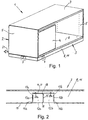
- FIG. 1 A piece of furniture according to the invention is shown with a furniture body 2 and a bottom skirting board 3.
- the furniture 1 is box-like, the furniture body 2 having a front wall 4, two side walls 5, a bottom 6, an upper wall 7 and one in Figure 1 has hidden rear wall.
- the furniture body 2 is largely open on its front.
- the type, shape and functionality of the furniture 1 can, however, be varied within the scope of the present invention and are in no way limited to the exemplary embodiment shown.
- the skirting board 3 which is preferably completely circumferential in the edge region of the base 6, consists at least predominantly of a metal sheet.
- the skirting board 3 can be designed in such a way that it supports the furniture body 2, or, if the furniture body 2 rests on separate feet (not shown), it can only be a base panel without a supporting function.
- skirting boards are understood to mean both supporting skirting boards and non-supporting skirting boards.
- the skirting board 3 has a vertical skirting board wall 8, which consists of a material that can be deformed by bending.
- the skirting board wall 8 expediently consists of a metal sheet.
- the skirting board wall 8 has a section 9 on each side of the furniture 1, which section is intended to form a cable bushing 10. These sections 9 can be arranged on each side of the furniture 1 or only on certain sides, in particular on the back of the furniture 1. Furthermore, it is also readily possible for a plurality of sections 9 to be provided on one or more sides of the furniture 1. Furthermore, it is also possible that such sections 9 are not provided or not only in the skirting board wall 8, but in another wall of the furniture 1 if this wall consists of a material that can be deformed by bending. Such a wall, in particular the skirting board wall 8, is therefore more generally referred to below as a furniture wall 11.
- Figure 2 shows a section of the skirting board 3 in isolation in the area of a section 9, which is intended to form a cable bushing 10.
- the section 9 comprises two bending tabs 12a, 12b, which are each formed by a partially cut-out section of the furniture wall 11.
- the bending tabs 12a, 12b are each separated from the adjacent edge regions of the furniture wall 11 by a vertical longitudinal slot 13a, 13b located on the outside and by an upper, continuous, horizontal longitudinal slot 14 over the majority of their circumferences.
- the two adjacent bending tabs 12a, 12b are separated from one another by a central vertical longitudinal slot 15 over the major part of their height.
- the lateral vertical longitudinal slots 13a, 13b have a length such that between the lower end of the vertical longitudinal slots 13a, 13b and the lower one Edge of the bending tabs 12a, 12b only a relatively narrow bridge section 16a, 16b or web is present. There is only a narrow bridge section 17a, 17b or web between the upper end of the vertical longitudinal slots 13a, 13b and the horizontal longitudinal slot 14.
- the two bending tabs 12a, 12b in the in Figure 2 Starting position shown, in which they are aligned with the adjacent areas of the furniture wall 11, connected to one another by upper and lower connecting sections 18, which extend from the upper end of the central vertical longitudinal slot 15 to the horizontal longitudinal slot 15 and from the lower end of the central vertical longitudinal slot 15 to extend to the lower edge of the bending tabs 12a, 12b.
- These connecting sections 18 form a predetermined dividing line and can be designed such that they can be severed in a simple manner, for example by having a smaller wall thickness than the bending tabs 12a, 12b.
- the longitudinal slots 13a, 13b, 14 are expediently formed by punching out the continuous furniture wall 11 which is flat in the initial state.
- the bending tabs 12a, 12b Due to the longitudinal slots 13a, 13b, 14 it is possible, after severing the connecting sections 18, to bend the bending tabs 12a, 12b inwards in a simple manner, the bending tabs being pivoted about the vertical pivot axes lying in the region of the vertical longitudinal slots 13a, 13b and the bridge sections 16a, 17a and 16b, 17b are bent accordingly.
- the bending flaps 12a, 12b are expediently bent inwards in such a way that they are arranged at an angle of 90 ° to the adjacent areas of the furniture wall 11.
- the bending tabs 12a, 12b are square or rectangular in shape and, in the exemplary embodiment shown, extend from the lower edge 19 of the skirting board 3 over most of the height of the skirting board 3. However, the height and width of the bending tabs 12a, 12b can vary widely.
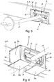
- a cable bushing 10 ( Figure 5 ) are installed in order to lead a cable 21 through the baseboard 3, the connecting sections 18 are severed, for example by means of a saw or sheet metal shears, as a result of which the bending tabs 12a, 12b can be bent inwards.
- Figure 3 shows the bending tabs 12a, 12b in their inwardly bent open position, in which they are opened like a door leaf. In this open position, the bending tabs 12a, 12b laterally delimit a wall opening 20 in the baseboard 3.
- This wall opening 20 is used to insert a sleeve-shaped plug-in frame that lines the wall opening 20.
- the plug-in frame 22 expediently consists of a one-piece plastic part. Other materials and a plug-in frame 22 composed of several parts are also possible.
- the plug-in frame 22 comprises side walls 23, a bottom 24, a top wall 25 and an outer end wall 26 which projects laterally and upwards over the side walls 23 and top wall 25.
- the width of the plug-in frame 22 is dimensioned in the region of the side walls 23 such that when the plug-in frame 22 is inserted into the wall opening 20, they rest on the bent bending tabs 12a, 12b.
- the insertion frame 22 also has, as from the Figures 3 and 4 It can be seen that upper webs 27 and lower webs 28 project laterally outwards over the side walls 23.
- the upper webs 27 are formed by a lateral extension of the ceiling wall 25, while the lower webs 28 are formed by a lateral extension of the bottom 24.
- the webs 27, 28 expediently extend over the entire depth or at least over the major part of the depth of the insertion frame 22, as a result of which a particularly good support effect can be achieved.
- an intermediate space 30 is formed which, after the bending of the bending flaps 12a, 12b, lateral grooves 31a, 31b ( Figure 3 ) between the upper bridge sections 17a, 17b and the upper edge 32 of the wall opening.
- the upper webs 27 of the plug-in frame 22 engage in these lateral grooves 31a, 31b.
- the lower webs 28 of the insertion frame 22 engage under the bending tabs 12a, 12b.
- the bending tabs 12a, 12b thus support the insertion frame 22 upwards and downwards, which contributes significantly to a firm, reliable fit of the insertion frame 22 within the wall opening 20.
- the width of the bending tabs 12a, 12b and the depth of the insertion frame 22 are expediently coordinated with one another in such a way that the bent bending tabs 12a, 12b extend at least over the vast majority of the depth of the insertion frame 22.
- the insert frame 22 is inserted into the wall opening 22 until the end wall 26 strikes the outside of the furniture wall 11.
- the end wall 26 thus protrudes over the edge of the wall opening 20 and forms an outer stop to limit the insertion path of the plug-in frame 22.
- a retaining projection 33 is formed on the top wall 25 of the plug-in frame 22, which in the inserted state of the plug-in frame 22 has the furniture wall 11 in this way engages behind that a displacement of the insertion frame 22 against the insertion direction is prevented.
- the retaining projection 33 is wedge-shaped with a run-on slope.
- the retaining projection 33 is arranged centrally on the plug-in frame 22.
- Other designs of the retaining projection 33 are readily possible, for example stable but resilient spring tongues.
- two or more retaining projections can also be provided, which are arranged distributed over the width of the plug-in frame 22.
- the plug-in frame 22 can be clipped into the skirting board 3 without tools and, since it is supported laterally on the furniture wall 11 between the front end wall 26 and the retaining projection 33 and additionally by the bending tabs 12a, 12b, is held firmly and reliably on the skirting board 3.
- the bottom 24 of the plug-in frame 22 is divided into two bottom sections 24a, 24b, which extend from the side walls 23 towards one another. However, the bottom sections 24a, 24b are spaced apart from one another, so that a gap 34 is formed in the middle of the plug-in frame 22 and is only bridged by a bridge element 35 with a reduced wall thickness.
- the bridge element 35 is designed in such a way that it can be severed in a simple manner in order, if necessary, to insert the cable 21 from below through the gap 34 into a cable passage space 36 enclosed by the plug-in frame 22. If it is not necessary to cut through the bridge element 35, since the plug-in frame 22 is of sufficiently large dimensions, the bridge element 35 stabilizes the base 24, since the plug-in frame 22 is then designed to be closed all around in the circumferential direction.
- the plug-in frame 22 is used to hold and hold a cable strain relief device 37, which in Figure 3 in exploded view and in the Figures 4 until 6 is shown in the assembled state.
- the cable strain relief device 37 comprises an upper part 38 and a lower part 39.
- Upper part 38 and lower part 39 consist of two separate components which can be detached from one another and connected to one another by means of a screw 40.
- the upper part 38 and lower part 39 are each bowl-shaped.
- semicircular cutouts 41, 42 are provided, which, when the upper part 38 and lower part 39 are assembled, form circular cutouts in order to receive and clamp cables 21 therein.
- the cable strain relief device 37 is designed to receive and clamp three cables arranged next to one another.
- the number of cable passages per cable strain relief device is variable and can also comprise only one or two cable passages or more than three cable passages. If the upper part 38 and lower part 39 are screwed together by means of the screw 40, the cable 21 passed through is firmly clamped inside the cable strain relief device 37, ie the cable strain relief device 37 is then firmly anchored to the cable 21.
- the cable strain relief device 37 has essentially the shape of a cuboid, the top wall 43 of the upper part 38 and the bottom 44 of the lower part 39 being flat.
- the cable strain relief device 37 is only positive and in the illustrated embodiment can be anchored without tools within the plug-in frame 22.
- the interlocking connection between the plug-in frame 22 and the cable strain relief device 37 comprises vertical webs 45 on the plug-in frame side, which protrude inwards from the side walls 23 of the plug-in frame 22.
- two mutually parallel webs 45 are provided on each side wall 23.
- the number of webs 45 can vary and, for example, can also be only one web 45 or three webs 45 per side wall 23.
- the webs 45 extend as from Figure 3 can be seen down to the bottom portions 24a, 24b. In contrast, the webs 45 do not extend all the way up to the ceiling wall 25, but are at a distance from this. This distance is dimensioned such that it is slightly larger than the thickness of lateral retaining strips 46 which are provided in the side regions of the upper part 38 of the cable strain relief device 37.
- these holding strips 46 are formed by a lateral extension of the top wall 43 of the upper part 38, which project laterally outwards via the side walls 47 of the upper part 38.
- Two guide grooves 48 are provided in each of the lateral holding strips 46, which are adapted to the webs 45 of the plug-in frame 22. Due to this design, the cable strain relief device 37 can be inserted into the insertion frame 22 in an elevated position, in which it is located directly below the ceiling wall 25 of the insertion frame 22, until the guide grooves 48 are aligned with the webs 45.
- the sections 9 of the skirting board 3 thus form, with the plug-in frame 22 and the cable strain relief device 37, a cable bushing 10 for the skirting board 3, which, after the bending flaps 12a, 12b have been bent over, enables the cable strain relief device 37 to be simply, securely and without tools on the skirting board 3.
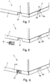
- a piece of furniture 1 is initially provided with a baseboard 3, which preferably has a plurality of partially free-cut sections 9 provided at different locations on the baseboard 3 for the formation of a cable duct 10.
- the right section 9 is shown in the initial state, in which the bending tabs 12a, 12b are aligned with the adjoining skirting board wall 8 or furniture wall 11.
- the left section 9, however, is shown in a state in which the bending tabs 12a, 12b are bent inwards transversely to the skirting board wall 8 or furniture wall 11, as a result of which a wall opening 20 is created in the skirting board 3.
- the connecting sections 18 between the bending tabs 12a, 12b are severed.
- the plug-in frame 22 is guided from the outside, for example from the rear of the furniture 1, to the wall opening 20 and inserted into the latter until the end wall 26 of the plug-in frame 22 on the skirting board wall 8 / furniture wall 11 abuts and the retaining projection 33 hits the adjacent area of the skirting board wall 8 / furniture wall 11.
- the plug-in frame 22 is brought into holding engagement with the edge region of the skirting board wall 8 / furniture wall 11 surrounding the plug-in frame 22 and with the bending tabs 12a, 12b.
- the cable 21 passed through the insertion frame 22. If the cable 21 does not have an end part that is larger than the inner passage width of the plug-in frame 22, it is not necessary to cut the bridge element 35 between the bottom sections 24a, 24b. Otherwise, the bridge part 35 is separated or removed in order to be able to pass the cable 21 between the bottom sections 24a, 24b.
- the cable strain relief device 37 can now be inserted into the plug-in frame 22 and anchored in this in a form-fitting manner.
- the insertion takes place in a raised position of the cable strain relief device 37 relative to the plug-in frame 22. If the cable strain relief device 37 is subsequently moved downward within the plug-in frame 22, the form-fitting connection elements of the cable strain-relief device 37 interact with the form-fitting connection elements of the plug-in frame 22 which are matched thereto such that a movement of the Cable strain relief device 37 and thus the cable 21 is blocked in the longitudinal direction of the cable passage space 36.
- the interlocking locking device between cable strain relief device 37 and plug-in frame 22 can also be implemented in another way.
- the cable strain relief device 37 it is possible to design the cable strain relief device 37 as a rotating body with outer locking pins that can be inserted into the plug-in frame 22 in a first rotational position and, after turning the cable strain relief device 37, engage in a groove that is arranged in a peripheral wall of the plug-in frame 22.
- the webs 45 can also be arranged on the cable strain relief device 37 and the guide grooves 48 on the plug-in frame 22.
Description
Die Erfindung betrifft ein Möbel mit Kabeldurchführung, die in einer Möbelwand, insbesondere in einer Sockelleistenwand, vorgesehen ist, gemäß Anspruch 1, sowie ein Verfahren zum Ausbilden einer derartigen Kabeldurchführung gemäß Anspruch 12.The invention relates to a piece of furniture with a cable bushing, which is provided in a furniture wall, in particular in a skirting board wall, according to
Möbel wie beispielsweise Sideboards, Schränke oder dergleichen weisen häufig Sockelleisten oder Sockelblenden auf, auf denen der Möbelkorpus aufgesetzt ist oder die, falls das Möbelstück auf separaten Füßen ruht, zum Abdecken des Zwischenraums zwischen Möbelkorpus und Boden dienen.Furniture such as sideboards, cupboards or the like often have skirting boards or plinths on which the furniture body is placed or which, if the piece of furniture rests on separate feet, serve to cover the space between the furniture body and the floor.
Bei derartigen Möbeln ist es häufig erforderlich, Kabel, beispielsweise Strom- oder Datenkabel in das Innere des Möbels hineinzuführen, um dort elektrische oder elektronische Geräte anschließen zu können.With such furniture, it is often necessary to lead cables, for example power or data cables, into the interior of the furniture in order to be able to connect electrical or electronic devices there.
Beispielsweise wird im Inneren des Möbelstücks Strom benötigt, wenn dort Steckdosen vorgesehen werden sollen oder wenn in das Möbelstück ein elektrisch höhenverstellbarer Tischfuß hineinragt, dessen Antrieb mit Strom versorgt werden muss.For example, electricity is required inside the piece of furniture if sockets are to be provided there or if an electrically height-adjustable table leg projects into the piece of furniture, the drive of which must be supplied with current.
Um durch Sockelleisten hindurch ein Kabel einzuführen, werden üblicherweise Kabeldurchführungen verwendet, die lediglich aus einer ausreichend dimensionierten Aussparung oder Öffnung in der Sockelleiste bestehen. Die Kabel werden dann lose durch diese Aussparung hindurch bis zur Anschlussstelle des Kabels innerhalb des Möbels geführt. Die erforderliche Zugentlastung für das Kabel ist dann im Bereich dieser Anschlussstelle vorgesehen. Wird auf das Kabel eine äußere Zugkraft aufgebracht, setzt sich diese bis zur Anschlussstelle innerhalb des Möbels fort. Weiterhin ist bei einer derartigen Kabeldurchführung nachteilig, dass keine definierte Kabellänge zwischen der Sockelleiste und der Anschlussstelle im Inneren des Möbels eingestellt und zuverlässig aufrechterhalten werden kann. Aus dem Stand der Technik sind Möbel mit Kabeldurchführungen zum Beispiel aus den Patentschriften
Der Erfindung liegt daher die Aufgabe zu Grunde, ein Möbel mit einer Kabeldurchführung zu schaffen, die einfach hergestellt werden kann und eine wirkungsvolle, einfach zu montierende Zugentlastung für Kabel aufweist. Weiterhin soll ein Verfahren zum einfachen Ausbilden einer Kabeldurchführung mit einer Kabelzugentlastung in einer Sockelleiste von Möbeln geschaffen werden.The invention is therefore based on the object of creating a piece of furniture with a cable bushing that can be easily manufactured and has an effective, easy-to-install strain relief for cables. Furthermore, a method for the simple formation of a cable bushing with a cable strain relief in a skirting board of furniture is to be created.
Diese Aufgabe wird erfindungsgemäß durch ein Möbel mit einer Kabeldurchführung mit den Merkmalen des Anspruchs 1 und ein Verfahren zum Ausbilden einer Kabeldurchführung gemäß Merkmal 12 gelöst. Vorteilhafte Ausführungsformen der Erfindung sind in den weiteren Ansprüchen beschrieben.This object is achieved by a piece of furniture with a cable duct with the features of the
Das erfindungsgemäße Möbel weist eine Kabeldurchführung, die in einer Möbelwand, insbesondere in einer Sockelleistenwand, vorgesehen ist, sowie folgende Merkmale auf:
- die Möbelwand weist eine Wandöffnung auf, die seitlich durch mindestens eine Biegelasche begrenzt ist, die durch einen teilweise freigeschnittenen Abschnitt der Möbelwand gebildet wird,
- innerhalb der Wandöffnung ist ein einen Kabeldurchgangsraum begrenzender Einsteckrahmen angeordnet, der mit einem die Wandöffnung begrenzenden Randbereich der Möbelwand und der Biegelasche in Halteeingriff ist,
- innerhalb des Einsteckrahmens ist eine Kabelzugentlastungseinrichtung befestigbar, die zum Festklemmen eines Kabels ausgebildet ist,
- wobei der Einsteckrahmen und die Kabelzugentlastungseinrichtung eine Formschlussverbindungseinrichtung aufweisen, die derart ausgebildet ist, dass die Kabelzugentlastungseinrichtung und der Einsteckrahmen durch Verschieben oder Verdrehen der Kabelzugentlastungseinrichtung innerhalb des Einsteckrahmens miteinander in formschlüssigen Halteeingriff bringbar sind, wodurch eine Bewegung der Kabelzugentlastungseinrichtung längs des Kabeldurchgangsraums blockiert ist.
- the furniture wall has a wall opening which is laterally delimited by at least one bending tab which is formed by a partially cut-out section of the furniture wall,
- a plug-in frame which delimits a cable passage space is arranged within the wall opening and is held in engagement with an edge region of the furniture wall and the bending flap which delimits the wall opening,
- A cable strain relief device, which is designed to clamp a cable, can be fastened within the plug-in frame,
- wherein the plug-in frame and the cable strain relief device have a form-locking connection device which is designed such that the cable strain relief device and the plug-in frame can be brought into positive locking engagement with one another by moving or rotating the cable strain relief device within the plug-in frame, as a result of which movement of the cable strain relief device along the cable passage space is blocked.
Das erfindungsgemäße Verfahren zum Ausbilden einer Kabeldurchführung mit einer Kabelzugentlastung in einer Möbelwand, insbesondere in einer Sockelleistenwand von Möbeln, ist durch folgende Schritte gekennzeichnet:
- Bereitstellen eines Möbels mit einer Möbelwand, die mindestens eine Biegelasche aufweist, die gegenüber der angrenzenden Möbelwand teilweise abgetrennt oder über definierte Solltrennstellen teilweise abtrennbar ist,
- Umbiegen der Biegelasche in eine zur angrenzenden Möbelwand abgewinkelte Öffnungsstellung, um in der Möbelwand eine Wandöffnung zu bilden,
- Einstecken eines Einsteckrahmens in die Wandöffnung, wobei der Einsteckrahmen mit einem die Wandöffnung begrenzenden Randbereich der Möbelwand und der mindestens einen Biegelasche in Halteeingriff gebracht wird,
- Festklemmen eines Kabels an oder in einer Kabelzugentlastungseinrichtung außerhalb des Einsteckrahmens,
- Einführen der Kabelzugentlastungseinrichtung in den Einsteckrahmen,
- Verankern der Kabelzugentlastungseinrichtung innerhalb des Einsteckrahmens durch Verschieben oder Drehen der Kabelzugentlastungseinrichtung, derart, dass die Kabelzugentlastungseinrichtung in formschlüssigen Halteeingriff mit dem Einsteckrahmen gebracht wird.
- Providing a piece of furniture with a furniture wall that has at least one bending tab that is partially separated from the adjacent furniture wall or that can be partially separated via defined predetermined separation points,
- Bending the bending tab into an opening position angled to the adjacent furniture wall in order to form a wall opening in the furniture wall,
- Inserting a plug-in frame into the wall opening, the plug-in frame being brought into holding engagement with an edge region of the furniture wall delimiting the wall opening and the at least one bending tab,
- Clamping a cable on or in a cable strain relief device outside the plug-in frame,
- Inserting the cable strain relief device into the plug-in frame,
- Anchoring the cable strain relief device within the plug-in frame by moving or rotating the cable strain relief device in such a way that the cable strain relief device is brought into a form-fitting holding engagement with the plug-in frame.
Mit Hilfe der Erfindung wird eine Kabeldurchführung geschaffen, die bei Bedarf auf schnelle und einfache Weise hergestellt werden kann und ein einfaches, schnelles Befestigen einer Kabelzugentlastungseinrichtung an einer Wand, insbesondere an der Sockelleistenwand eines Möbelstücks ermöglicht. Die Sockelleiste kann dabei derart ausgebildet sein, dass an vorzugsweise mehreren Stellen der Sockelleiste eine Biegelasche oder ein nebeneinander angeordnetes Paar von Biegelaschen vorgesehen ist, die bzw. das durch einen teilweise frei geschnittenen Abschnitt der Sockelleistenwand gebildet wird. Solange diese Biegelaschen noch nicht in die abgewinkelte Stellung umgebogen sind, verlaufen sie in der Hauptebene der Möbelwand und decken die bei Bedarf herzustellenden Wandöffnungen bündig ab. An den Stellen, an denen die Biegelaschen nicht umgebogen werden, bleiben die Wandöffnungen somit verschlossen. Dadurch, dass die Biegelaschen jedoch teilweise freigeschnitten und nur an den zum Umbiegen bestimmten Stellen durch Brückenabschnitte mit der Möbelwand verbunden sind, ist das Umbiegen der Biegelaschen in die abgewinkelte Öffnungsstellung auf einfache Weise möglich. Die abgewinkelten Biegelaschen dienen zum Abstützen des Einsteckrahmens, wodurch dieser sicher in der Sockelleiste gehalten wird und auf einfache Weise, insbesondere werkzeuglos, in die Wandöffnung eingesteckt werden kann. Die Biegelaschen haben somit eine zweifache Funktion, nämlich einerseits die Wandöffnung im ungeöffneten Zustand abzudecken, und andererseits den Einsteckrahmen, vorzugweise im Bereich beider Seitenwände des Einsteckrahmens, zu stützen. Dadurch, dass die Kabelzugentlastungseinrichtung formschlüssig mit dem Einsteckrahmen in Halteeingriff gebracht werden kann, ist eine werkzeuglose, einfache und schnelle Festlegung der Kabelzugentlastungseinrichtung innerhalb des Einsteckrahmens möglich.With the help of the invention, a cable bushing is created, which can be produced in a quick and simple manner if required, and a simple, fast fastening a cable strain relief device on a wall, in particular on the skirting board wall of a piece of furniture. The skirting board can be designed in such a way that a bending tab or a pair of bending tabs arranged next to one another is provided at preferably several locations on the skirting board, which is formed by a partially cut section of the skirting board wall. As long as these bending tabs have not yet been bent into the angled position, they run in the main plane of the furniture wall and cover the wall openings to be made as required. The wall openings remain closed at the points where the bending tabs are not bent. However, because the bending tabs are partially cut free and are only connected to the furniture wall by bridge sections at the points intended for bending, bending of the bending tabs into the angled open position is possible in a simple manner. The angled bending brackets serve to support the insertion frame, as a result of which it is held securely in the skirting board and can be inserted into the wall opening in a simple manner, in particular without tools. The bending tabs therefore have a dual function, namely to cover the wall opening in the unopened state on the one hand and to support the insertion frame, preferably in the region of both side walls of the insertion frame, on the other hand. The fact that the cable strain relief device can be positively engaged with the plug-in frame means that the cable strain relief device can be fixed within the plug-in frame quickly and easily without tools.
Gemäß einer vorteilhaften Ausführungsform wird die Wandöffnung seitlich durch zwei Biegelaschen begrenzt, die aus zwei nebeneinander angeordneten Wandabschnitten der Möbelwand gebildet werden, die türflügelartig ausgebildet und von einer geschlossenen Ausgangsstellung, in der sie in einer Hauptebene der Möbelwand liegen, in eine Öffnungsstellung biegbar sind. Die Biegeachse, um welche jede Biegelasche schwenkbar ist, ist dabei vertikal im seitlichen Randbereich der jeweiligen Biegelasche angeordnet.According to an advantageous embodiment, the wall opening is laterally delimited by two bending flaps, which are formed from two wall sections of the furniture wall arranged next to one another, which are designed like door wings and can be bent into an open position from a closed starting position, in which they lie in a main plane of the furniture wall. The bending axis, about which each bending tab can be pivoted, is arranged vertically in the lateral edge area of the respective bending tab.
Alternativ hierzu ist es jedoch auch möglich, dass eine Wandöffnung nur durch eine einzige umbiegbare Biegelasche abgedeckt wird. In diesem Fall wird der Einsteckrahmen nur einseitig durch die umgebogene Biegelasche gestützt.As an alternative to this, however, it is also possible for a wall opening to be covered only by a single bendable bending tab. In this case, the push-in frame is only supported on one side by the bent flap.
Sind für eine Wandöffnung zwei nebeneinander liegende Biegelaschen vorgesehen, sind diese in ihrer Ausgangsstellung vorzugsweise mittels mindestens eines trennbaren Verbindungsabschnitts miteinander verbunden. Dieser Verbindungsabschnitt stabilisiert die beiden Biegelaschen im ungeöffneten Zustand, d.h. wenn sie sich in der Ebene der Möbelwand befinden. Ein versehentliches Verbiegen der Biegelaschen wird hierdurch verhindert. Soll an der betreffenden Stelle eine Kabeldurchführung geschaffen werden, wird der Verbindungsabschnitt durchtrennt, so dass die Biegelaschen nach innen umgebogen werden können. Es ist ohne weiteres möglich, dass der Verbindungsabschnitt eine geringere Wandstärke als die Möbelwand aufweist, so dass das Trennen der beiden Biegelaschen auf besonders einfache Weise möglich ist. Vorzugsweise sind die Biegelaschen mit der angrenzenden Möbelwand jeweils lediglich über mindestens einen leicht biegbaren Brückenabschnitt verbunden, der sich in einem seitlich äußeren Randbereich der Biegelaschen befindet. Vorzugsweise sind pro Biegelasche zwei derartige Brückenabschnitte vorgesehen, wobei sich ein derartiger Brückenabschnitt im unteren Endbereich der Biegelasche und der zweite Brückenabschnitt nahe dem oberen Endbereich der jeweiligen Biegelasche angeordnet ist, während die Biegelaschen zwischen diesen beiden Brückenabschnitten durch entsprechende Längsschlitze abgetrennt ist.If two bending tabs lying next to one another are provided for a wall opening, these are preferably connected to one another in their starting position by means of at least one separable connecting section. This connecting section stabilizes the two bending tabs in the unopened state, ie when they are in the plane of the furniture wall. This prevents accidental bending of the bending tabs. If a cable duct is to be created at the point in question, the connecting section is severed so that the bending tabs can be bent inwards. It is easily possible for the connecting section to have a smaller wall thickness than the furniture wall, so that the two bending tabs can be separated in a particularly simple manner. The bending tabs are preferably each connected to the adjacent furniture wall only via at least one easily bendable bridge section, which is located in a laterally outer edge region of the bending tabs. Preferably, two such bridge sections are provided per bending bracket, such a bridge section being arranged in the lower end region of the bending bracket and the second bridge section near the upper end region of the respective bending bracket, while the bending bracket between these two bridge sections is separated by corresponding longitudinal slots.
Vorzugsweise weist der Einsteckrahmen seitlich vorspringende Stege auf, die ausgebildet sind, die sich in der Öffnungsstellung befindenden Biegelaschen zu über- und untergreifen. Zweckmäßigerweise werden diese Stege durch seitliche Verlängerungen der Decken- und Bodenwand des Einsteckrahmens gebildet, welche seitlich über die Seitenwände des Einsteckrahmens vorstehen.The insertion frame preferably has laterally projecting webs which are designed to reach over and under the bending tabs which are in the open position. These webs are expediently formed by lateral extensions of the top and bottom walls of the plug-in frame, which protrude laterally beyond the side walls of the plug-in frame.
Vorteilhafterweise haben die Biegelaschen einen oberen Rand, der in vertikaler Richtung zur angrenzenden Möbelwand beabstandet ist, so dass ein Zwischenraum gebildet wird, in den sich seitlich vorspringende Stege des Einsteckrahmens hinein erstrecken können.The bending tabs advantageously have an upper edge which is spaced apart in the vertical direction from the adjacent furniture wall, so that an intermediate space is formed, into which laterally projecting webs of the plug-in frame can extend.
Vorteilhafterweise weist der Einsteckrahmen einen äußeren Anschlag, der im eingesteckten Zustand des Einsteckrahmens an der Außenseite der Möbelwand anliegt, und mindestens einen Rückhaltevorsprung auf, der im eingesteckten Zustand des Einsteckrahmens die Möbelwand derart hintergreift, dass ein Verschieben entgegen der Einsteckrichtung verhindert wird. Die an der Außenseite der Möbelwand zur Anlage bringbare äußere Anschlag besteht zweckmäßigerweise aus der vorderen Stirnwand des Einsteckrahmens, welcher seitlich und nach oben über die Seitenwände bzw. Deckenwand des Einsteckrahmens so weit vorsteht, dass die Randbereiche der die Wandöffnung umgebenden Möbelwand übergriffen wird. Der am Einsteckrahmen vorgesehene Rückhaltevorsprung besteht zweckmäßigerweise aus einer über die Deckenwand des Einsteckrahmens nach oben vorstehenden Rastnase mit Anlaufschräge, so dass der Einsteckrahmen clipartig an der Möbelwand verrastet werden kann.Advantageously, the plug-in frame has an outer stop which bears against the outside of the furniture wall when the plug-in frame is inserted, and at least one retaining projection which engages behind the furniture wall in the inserted state of the plug-in frame in such a way that it is prevented from moving against the direction of insertion. The one on the outside of the Furniture wall that can be brought into contact with the outer stop expediently consists of the front end wall of the plug-in frame, which projects laterally and upwards beyond the side walls or top wall of the plug-in frame so that the edge areas of the furniture wall surrounding the wall opening are overlapped. The retaining projection provided on the plug-in frame expediently consists of a locking lug projecting upward above the ceiling wall of the plug-in frame, with a bevel so that the plug-in frame can be locked in a clip-like manner on the furniture wall.
Gemäß einer vorteilhaften Ausführungsform weist der Einsteckrahmen bodenseitig einen Spalt oder ein definierten Brückenelement mit Solltrennstelle zur Bildung eines Spaltes auf, durch den ein Kabel in den Einsteckrahmen einführbar ist. Ein derartiger Spalt ist immer dann vorteilhaft, wenn die Höhe des Einsteckrahmens nicht ausreicht, um einen Kabelstecker in Längsrichtung des Kabeldurchführraums hindurchführen zu können. Der Brückenbereich stabilisiert im intakten Zustand die Bodenwand des Einsteckrahmens und ermöglicht andererseits ein einfaches Herstellen des Spalts, falls dies erforderlich sein sollte.According to an advantageous embodiment, the plug-in frame has a gap on the bottom or a defined bridge element with a predetermined separation point to form a gap through which a cable can be inserted into the plug-in frame. Such a gap is always advantageous when the height of the plug-in frame is not sufficient to be able to pass a cable plug in the longitudinal direction of the cable lead-through space. The bridge area stabilizes the base wall of the plug-in frame when intact and, on the other hand, enables the gap to be easily produced if this should be necessary.
Vorteilhafterweise umfasst die Formschlussverbindungseinrichtung, die zwischen dem Einsteckrahmen und der Kabelzugentlastungseinrichtung vorgesehen ist, Stege, die von Seitenwänden des Einsteckrahmens in den Kabeldurchgangsraum hinein vorstehen, und Nuten, die an der Kabelzugentlastungseinrichtung angeordnet und in Eingriff mit den Stegen bringbar sind. Die Stege und Nuten sind dabei derart angeordnet, dass die Kabelzugentlastungseinrichtung an einer bestimmten Stelle des Einsteckrahmens in diesen eingeführt und durch eine weitere Bewegung dann derart im Einsteckrahmen verlagert werden kann, dass sie in Längsrichtung des Kabels nicht mehr aus dem Einsteckrahmen und damit nicht mehr aus der Sockelleiste herausgezogen werden kann.Advantageously, the interlocking connection device which is provided between the plug-in frame and the cable strain relief device comprises webs which protrude from side walls of the plug-in frame into the cable passage space, and grooves which are arranged on the cable strain relief device and can be brought into engagement with the webs. The webs and grooves are arranged such that the cable strain relief device inserted at a certain point in the plug-in frame and then moved by a further movement in the plug-in frame in such a way that it can no longer be pulled out of the plug-in frame in the longitudinal direction of the cable and thus no longer be pulled out of the baseboard.
Vorteilhafterweise bestehen die Stege des Einsteckrahmens aus an der Innenseite der Seitenwände des Einsteckrahmens angeordneten vertikalen Steg mit einem oberen Ende, das zur Deckenwand des Einführrahmens beabstandet ist, so dass zwischen Steg und Deckenwand ein Einführspalt vorhanden ist. Weiterhin umfasst die Formschlussverbindungseinrichtung vorteilhafterweise an der Kabelzugentlastungeinrichtung vorgesehene seitliche Halteleisten, in denen Führungsnuten vorgesehen ist, die zum Halteingriff mit den Stegen ausgebildet sind. Hierdurch ist es möglich, die Kabelzugentlastungseinrichtung in einer erhöhten Stellung in den Einführspalt zwischen Vertikalsteg und Deckenwand des Einsteckrahmens in den Einsteckrahmen einzuführen, bis die Nuten der Kabelzugentlastungseinrichtung mit den vertikalen Stegen fluchten, und anschließend die Kabelzugentlastungseinrichtung abzusenken, wodurch die Stege in die Nuten eingreifen.The webs of the plug-in frame advantageously consist of vertical webs arranged on the inside of the side walls of the plug-in frame and having an upper end which is spaced apart from the top wall of the insertion frame, so that an insertion gap is present between the web and the top wall. Furthermore, the positive-locking connection device advantageously comprises lateral holding strips provided on the cable strain relief device, in which guide grooves are provided, which are designed for holding engagement with the webs. This makes it possible to insert the cable strain relief device in an elevated position into the insertion gap between the vertical web and the top wall of the plug-in frame until the grooves of the cable strain relief device are aligned with the vertical webs, and then to lower the cable strain relief device, as a result of which the webs engage in the grooves.
Vorteilhafterweise umfasst die Kabelzugentlastungseinrichtung ein Oberteil und ein Unterteil, zwischen denen mindestens ein Kabel festklemmbar ist, wobei das Oberteil Seitenwände und eine plattenförmige Deckenwand aufweist, die seitlich über die Seitenwände vorsteht und die Halteleisten bildet.Advantageously, the cable strain relief device comprises an upper part and a lower part, between which at least one cable can be clamped, the upper part having side walls and a plate-shaped ceiling wall which protrudes laterally beyond the side walls and forms the retaining strips.
Die Erfindung wird nachfolgend anhand der Zeichnungen beispielhaft näher erläutert. Diese zeigen:
- Figur 1:
- ein erfindungsgemäßes Möbelstück mit einer Sockelleiste mit mehreren für eine Kabeldurchführung vorgesehenen Bereichen,
- Figur 2:
- einen Abschnitt einer Sockelleiste mit zwei nebeneinander angeordneten Biegelaschen,
- Figur 3:
- einen Abschnitt einer Sockelleiste mit einer Wandöffnung sowie einem Einsteckrahmen und einer Kabelzugentlastungseinrichtung in Explosionsdarstellung, wobei eine Ansicht von der Außenseite des Möbelstücks her dargestellt ist,
- Figur 4:
- die erfindungsgemäße Kabeldurchführung in montiertem Zustand ohne Kabel, wobei eine Ansicht von der Innenseite des Möbelstücks her schräg von unten dargestellt ist,
- Figur 5:
- eine räumliche Darstellung der montierten Kabeldurchführung mit Kabel, von der Außenseite des Möbelstücks her gesehen,
- Figur 6:
- eine räumliche Darstellung der montierten Kabeldurchführung mit Kabel, von der Innenseite des Möbelstücks her schräg von unten gesehen,
- Figuren 7 - 12:
- einen Ausschnitt eines erfindungsgemäßen Möbels, von außen gesehen, wobei einzelne Schritte zur Ausbildung der Kabeldurchführung dargestellt sind.
- Figure 1:
- a piece of furniture according to the invention with a baseboard with a plurality of areas provided for a cable duct,
- Figure 2:
- a section of a baseboard with two bending tabs arranged next to one another,
- Figure 3:
- a section of a skirting board with a wall opening and a plug-in frame and a cable strain relief device in an exploded view, a view from the outside of the piece of furniture is shown,
- Figure 4:
- the cable bushing according to the invention in the assembled state without a cable, a view from the inside of the piece of furniture being shown obliquely from below,
- Figure 5:
- a spatial representation of the assembled cable entry with cable, seen from the outside of the piece of furniture,
- Figure 6:
- a spatial representation of the assembled cable entry with cable, seen obliquely from below from the inside of the piece of furniture,
- Figures 7 - 12:
- a section of a piece of furniture according to the invention, seen from the outside, individual Steps for forming the cable duct are shown.
In
Die im Randbereich des Bodens 6 vorzugsweise vollständig umlaufende Sockelleiste 3 besteht zumindest überwiegend aus einem Metallblech. Die Sockelleiste 3 kann derart ausgebildet sein, dass sie den Möbelkorpus 2 trägt, oder kann, wenn der Möbelkorpus 2 auf separaten, nicht dargestellten Füßen ruht, lediglich eine Sockelblende ohne tragende Funktion sein. Als Sockelleisten werden im Rahmen der vorliegenden Erfindung somit sowohl tragende Sockelleisten als auch nicht tragende Sockelblenden verstanden.The
Die Sockelleiste 3 weist eine vertikale Sockelleistenwand 8 auf, die aus einem Material besteht, das durch Biegen umgeformt werden kann. Zweckmäßigerweise besteht die Sockelleistenwand 8 aus einem Metallblech.The
Die Sockelleistenwand 8 weist auf jeder Seite des Möbels 1 einen Abschnitt 9 auf, der zur Bildung einer Kabeldurchführung 10 bestimmt ist. Diese Abschnitte 9 können auf jeder Seite des Möbels 1 oder nur auf bestimmten Seiten, insbesondere auf der Rückseite des Möbels 1, angeordnet sein. Weiterhin ist es auch ohne weiteres möglich, dass auf einer oder mehreren Seiten des Möbels 1 mehrere Abschnitte 9 vorgesehen sind. Weiterhin ist es auch möglich, dass derartige Abschnitte 9 nicht oder nicht nur in der Sockelleistenwand 8 vorgesehen sind, sondern in einer anderen Wand des Möbels 1, wenn diese Wand aus einem Material besteht, das durch Biegen umgeformt werden kann. Eine derartige Wand, insbesondere die Sockelleistenwand 8, wird im Folgenden daher allgemeiner auch als Möbelwand 11 bezeichnet.The skirting board wall 8 has a section 9 on each side of the
Aufgrund der Längsschlitze 13a, 13b, 14 ist es möglich, nach dem Durchtrennen der Verbindungsabschnitte 18 die Biegelaschen 12a, 12b auf einfache Weise nach innen umzubiegen, wobei die Biegelaschen um die im Bereich der vertikalen Längsschlitze 13a, 13b liegenden vertikalen Schwenkachsen geschwenkt und die Brückenabschnitte 16a, 17a bzw. 16b, 17b entsprechend umgebogen werden. Zweckmäßigerweise werden die Biegelaschen 12a, 12b derart nach innen umgebogen, dass sie in einem Winkel von 90° zu den angrenzenden Bereichen der Möbelwand 11 angeordnet sind.Due to the
Aus den
Die Biegelaschen 12a, 12b sind quadratisch oder rechteckig ausgebildet und erstrecken sich im gezeigten Ausführungsbeispiel vom unteren Rand 19 der Sockelleiste 3 über den überwiegenden Teil der Höhe der Sockelleiste 3. Die Höhe und Breite der Biegelaschen 12a, 12b kann jedoch in weitem Umfang variieren.The bending
Soll im Bereich der Biegelaschen 12a, 12b eine Kabeldurchführung 10 (
Diese Wandöffnung 20 dient zum Einstecken eines hülsenförmigen Einsteckrahmens, der die Wandöffnung 20 auskleidet. Der Einsteckrahmen 22 besteht zweckmäßigerweise aus einem einstückigen Kunststoffteil. Andere Materialien und ein aus mehreren Teilen zusammengesetzter Einsteckrahmen 22 sind ebenfalls möglich.This wall opening 20 is used to insert a sleeve-shaped plug-in frame that lines the
Der Einsteckrahmen 22 umfasst Seitenwände 23, einen Boden 24, eine Deckenwand 25 und eine äußere Stirnwand 26, die seitlich und nach oben über die Seitenwände 23 bzw. Deckenwand 25 vorsteht. Die Breite des Einsteckrahmens 22 ist im Bereich der Seitenwände 23 so bemessen, dass diese, wenn der Einsteckrahmen 22 in die Wandöffnung 20 eingesteckt wird, an den umgebogenen Biegelaschen 12a, 12b anliegen.The plug-in
Der Einsteckrahmen 22 weist ferner, wie aus den
Da ein oberer Rand 29a, 29b (
Die Breite der Biegelaschen 12a, 12b und die Tiefe des Einsteckrahmens 22 sind zweckmäßigerweise derart aufeinander abgestimmt, dass sich die umgebogenen Biegelaschen 12a, 12b zumindest über den ganz überwiegenden Teil der Tiefe des Einsteckrahmens 22 erstrecken.The width of the
Der Einsteckrahmen 22 wird soweit in die Wandöffnung 22 eingesteckt, bis die Stirnwand 26 an der Außenseite der Möbelwand 11 anschlägt. Die Stirnwand 26 steht somit über den Rand der Wandöffnung 20 vor und bildet einen äußeren Anschlag zur Begrenzung des Einschubwegs des Einsteckrahmens 22. Weiterhin ist an der Deckenwand 25 des Einsteckrahmens 22 ein Rückhaltevorsprung 33 ausgebildet, der im eingesteckten Zustand des Einsteckrahmens 22 die Möbelwand 11 derart hintergreift, dass ein Verschieben des Einsteckrahmens 22 entgegen der Einsteckrichtung verhindert wird. Um ein einfaches Einschieben des Einsteckrahmens 22 zu ermöglichen, ist der Rückhaltevorsprung 33 keilförmig mit einer Anlaufschräge ausgebildet. Im gezeigten Ausführungsbeispiel ist der Rückhaltevorsprung 33 mittig am Einsteckrahmen 22 angeordnet. Andere Ausbildungen des Rückhaltevorsprungs 33 sind ohne weiteres möglich, beispielsweise stabile, jedoch federnd nachgiebige Federzungen. Anstelle eines einzelnen mittigen Rückhaltevorsprungs 33 können auch zwei oder mehr Rückhaltevorsprünge vorgesehen sein, die über die Breite des Einsteckrahmens 22 verteilt angeordnet sind.The
Der Einsteckrahmen 22 kann werkzeuglos in die Sockelleiste 3 eingeclipst werden und wird, da er zwischen vorderer Stirnwand 26 und Rückhaltevorsprung 33 an der Möbelwand 11 und zusätzlich durch die Biegelaschen 12a, 12b seitlich abgestützt wird, fest und zuverlässig an der Sockelleiste 3 gehalten.The plug-in
Der Boden 24 des Einsteckrahmens 22 ist in zwei Bodenabschnitte 24a, 24b unterteilt, die sich von den Seitenwänden 23 aufeinander zu erstrecken. Die Bodenabschnitte 24a, 24b sind jedoch zueinander beabstandet, so dass ein in der Mitte des Einsteckrahmens 22 liegender Spalt 34 gebildet wird, der lediglich von einem Brückenelement 35 mit reduzierter Wanddicke überbrückt wird. Das Brückenelement 35 ist hierbei derart ausgebildet, dass es auf einfache Weise durchtrennt werden kann, um bei Bedarf das Kabel 21 von unten her durch den Spalt 34 hindurch in einen vom Einsteckrahmen 22 umschlossenen Kabeldurchgangsraum 36 einzuführen. Ist das Durchtrennen des Brückenelements 35 nicht erforderlich, da der Einsteckrahmen 22 ausreichend groß dimensioniert ist, stabilisiert das Brückenelement 35 den Boden 24, da dann der Einsteckrahmen 22 in Umfangsrichtung geschlossen umlaufend ausgebildet ist.The bottom 24 of the plug-in
Der Einsteckrahmen 22 dient zum Aufnehmen und festen Halten einer Kabelzugentlastungseinrichtung 37, die in
Die Kabelzugentlastungseinrichtung 37 hat im zusammengebauten Zustand im Wesentlichen die Form eines Quaders, wobei die Deckenwand 43 des Oberteils 38 und der Boden 44 des Unterteils 39 eben ausgebildet sind.In the assembled state, the cable
Die Kabelzugentlastungseinrichtung 37 ist im dargestellten Ausführungsbeispiel ausschließlich formschlüssig und werkzeuglos innerhalb des Einsteckrahmens 22 verankerbar. Die Formschlussverbindung zwischen Einsteckrahmen 22 und Kabelzugentlastungseinrichtung 37 umfasst einsteckrahmenseitig vertikale Stege 45, die von den Seitenwänden 23 des Einsteckrahmens 22 nach innen vorstehen. Im gezeigten Ausführungsbeispiel sind an jeder Seitenwand 23 zwei zueinander parallele Stege 45 vorgesehen. Die Anzahl der Stege 45 kann jedoch variieren und beispielsweise auch nur einen Steg 45 oder drei Stege 45 pro Seitenwand 23 betragen.The cable
Die Stege 45 erstrecken sich, wie aus
Diese Halteleisten 46 werden im gezeigten Ausführungsbeispiel durch eine seitliche Verlängerung der Deckenwand 43 des Oberteils 38 gebildet, die über die Seitenwände 47 des Oberteils 38 seitlich nach außen vorstehen. In den seitlichen Halteleisten 46 sind jeweils zwei Führungsnuten 48 vorgesehen, die an die Stege 45 des Einsteckrahmens 22 angepasst sind. Aufgrund dieser Ausbildung kann die Kabelzugentlastungseinrichtung 37 in einer erhöhten Position, in der sie sich unmittelbar unterhalb der Deckenwand 25 des Einsteckrahmens 22 befindet, in den Einsteckrahmen 22 eingeführt werden, bis die Führungsnuten 48 mit den Stegen 45 fluchten. Wird anschließend die Kabelzugentlastungseinrichtung 37 abgesenkt, greifen die Stege 45 in die Führungsnuten 48 ein, wodurch ein Verschieben der Kabelzugentlastungseinrichtung 37 in Längsrichtung des Kabeldurchgangsraums 36 blockiert ist und eine sichere Zugentlastung für das Kabel 21 im Bereich der Sockelleiste 3 geschaffen wird.In the exemplary embodiment shown, these holding
Die Abschnitte 9 der Sockelleiste 3 bilden somit mit dem Einsteckrahmen 22 und der Kabelzugentlastungseinrichtung 37 eine Kabeldurchführung 10 für die Sockelleiste 3, die nach dem Umbiegen der Biegelaschen 12a, 12b ein einfaches, sicheres und werkzeugloses Festlegen der Kabelzugentlastungseinrichtung 37 an der Sockelleiste 3 ermöglicht.The sections 9 of the
In den
Anhand der
Wie aus
Nach dem Herstellen der Wandöffnung 20 wird, wie aus Figur 8 ersichtlich, der Einsteckrahmen 22 von außen her, beispielsweise von der Rückseite des Möbels 1 her, an die Wandöffnung 20 herangeführt und in diese eingesteckt, bis die Stirnwand 26 des Einsteckrahmens 22 an der Sockelleistenwand 8 / Möbelwand 11 anliegt und der Rückhaltevorsprung 33 den angrenzenden Bereich der Sockelleistenwand 8 / Möbelwand 11 hitergreift. Der Einsteckrahmen 22 wird dabei mit dem den Einsteckrahmen 22 umgebenden Randbereich der Sockelleistenwand 8 / Möbelwand 11 und mit den Biegelaschen 12a, 12b in Halteeingriff gebracht.After the
Anschließend wird, wie aus
Anschließend wird, wie aus
Wie aus
Die formschlüssige Verriegelungseinrichtung zwischen Kabelzugentlastungseinrichtung 37 und Einsteckrahmen 22 kann auch auf andere Weise realisiert werden. Beispielweise ist es möglich, die Kabelzugentlastungseinrichtung 37 als Drehkörper mit äußeren Verriegelungszapfen auszubilden, die in einer ersten Drehstellung in den Einsteckrahmen 22 eingeführt werden können und nach einem Drehen der Kabelzugentlastungseinrichtung 37 in eine Nut eingreifen, die in einer Umfangswand des Einsteckrahmens 22 angeordnet ist. Weiterhin können die Stege 45 auch an der Kabelzugentlastungseinrichtung 37 und die Führungsnuten 48 am Einsteckrahmen 22 angeordnet sein.The interlocking locking device between cable
Claims (12)
- Piece of furniture having a cable feedthrough (10) which is provided in a furniture wall (11), in particular in a baseboard wall (8), comprising the following features:- the furniture wall (11) has a wall opening (20) which is laterally delimited by at least one bending tab (12a, 12b) which is formed by a partly cut-out portion (9) of the furniture wall (11),- an insertion frame (22) which delimits a cable passage space (36) is arranged within the wall opening (20) and is in holding engagement with an edge region of the furniture wall (11), which region delimits the wall opening (20), and the bending tab (12a, 12b),- a cable strain relief device (37) can be fastened within the insertion frame (22) and is designed for clamping a cable (21),- wherein the insertion frame (22) and the cable strain relief device (37) have a formfitting connection device which is designed such that the cable strain relief device (37) and the insertion frame (22) can be brought into formfitting holding engagement with one another within the insertion frame (22) by moving or rotating the cable strain relief device (37) such that movement of the cable strain relief device (37) along the cable passage space (36) is blocked.
- Piece of furniture according to claim 1, characterised in that the wall opening (20) is laterally delimited by two bending tabs (12a, 12b) which are formed from two wall portions of the furniture wall (11) that are arranged next to one another, are designed in the manner of a door leaf and can be bent into an open position from a closed initial position in which they are located in a main plane of the furniture wall (11).
- Piece of furniture according to claim 2, characterised in that the bending tabs (12a, 12b) are interconnected in the initial position thereof by means of at least one separable connection portion (18).
- Piece of furniture according to any of the preceding claims, characterised in that the bending tabs (12a, 12b) are connected to the adjacent furniture wall (11) in each case only by means of at least one easily bendable bridge portion (16a, 17a; 16b, 17b) which is located in a laterally outer edge region of the bending tabs (12a, 12b).
- Piece of furniture according to any of the preceding claims, characterised in that the insertion frame (22) has laterally projecting strips (27, 28) which are designed to engage above and below the bending tabs (12a, 12b) located in the open position.
- Piece of furniture according to claim 5, characterised in that the bending tabs (12a, 12b) have an upper edge (29a, 29b) which is spaced apart in the vertical direction from the adjacent furniture wall (11), such that a gap (30) is formed into which laterally projecting strips (27) of the insertion frame can extend (22).
- Piece of furniture according to any of the preceding claims, characterised in that the insertion frame (22) has an outer stop which abuts the outer side of the furniture wall (11) in the inserted state of the insertion frame (22), and at least one retaining projection (33) which engages the furniture wall (11) from behind in the inserted state of the insertion frame (22) such that movement counter to the insertion direction is prevented.
- Piece of furniture according to any of the preceding claims, characterised in that, on the bottom side, the insertion frame (22) has a gap (34) or a bridge element (35) having an intended separation point so as to form a gap (34) through which a cable (21) can be introduced into the insertion frame (22).
- Piece of furniture according to any of the preceding claims, characterised in that the formfitting connection device comprises strips (45) which project from lateral walls (23) of the insertion frame (22) into the cable passage space (36), and grooves (48) which are arranged on the cable strain relief device (37) and can be brought into engagement with the strips (45).
- Piece of furniture according to claim 9, characterised in that the strips (45) consist of vertical strips (45) having an upper end which is spaced apart from the top wall (25) of the insertion frame (22), such that there is an introduction gap between the strip (45) and the top wall (25), and in that there are lateral holding bars (46) on the cable strain relief device, in which bars the grooves (48) which are designed for holding engagement with the strips (45) are provided.
- Piece of furniture according to claim 10, characterised in that the cable strain relief device (37) comprises an upper part (38) and a lower part (39), between which at least one cable (21) can be clamped, the upper part (38) having lateral walls (47) and a planar top wall (43) which projects laterally beyond the lateral walls (47) and forms the holding bars (46).
- Method for forming a cable feedthrough (10), comprising a cable strain relief device (37) in a furniture wall (11), in particular in a baseboard wall (8) of pieces of furniture (1), characterised by the following steps:- providing a piece of furniture (1) having a furniture wall (11) which has at least one bending tab (12a, 12b) which is partly separated from the adjacent furniture wall (11) or can be partly separated by means of defined intended separation points,- bending the bending tab (12a, 12b) into an open position which is angled with respect to the adjacent furniture wall (11) in order to form a wall opening (20) in the furniture wall (11),- inserting a insertion frame (22) into the wall opening (20), the insertion frame (22) being brought into holding engagement with an edge region of the furniture wall (11), which region delimits the wall opening (20), and the at least one bending tab (12a, 12b),- clamping a cable (21) on or in a cable strain relief device (37) outside the insertion frame (22),- introducing the cable strain relief device (37) into the insertion frame (22),- anchoring the cable strain relief device (37) within the insertion frame (22) by moving or rotating the cable strain relief device (37) such that the cable strain relief device (37) is brought into formfitting holding engagement with the insertion frame (22).
Applications Claiming Priority (1)
| Application Number | Priority Date | Filing Date | Title |
|---|---|---|---|
| PCT/IB2017/001093 WO2019048897A1 (en) | 2017-09-08 | 2017-09-08 | Piece of furniture comprising a cable feedthrough and method for forming a cable feedthrough |
Publications (2)
| Publication Number | Publication Date |
|---|---|
| EP3558058A1 EP3558058A1 (en) | 2019-10-30 |
| EP3558058B1 true EP3558058B1 (en) | 2020-04-22 |
Family
ID=60153359
Family Applications (1)
| Application Number | Title | Priority Date | Filing Date |
|---|---|---|---|
| EP17787608.3A Active EP3558058B1 (en) | 2017-09-08 | 2017-09-08 | Piece of furniture comprising a cable feedthrough and method for forming a cable feedthrough |
Country Status (3)
| Country | Link |
|---|---|
| EP (1) | EP3558058B1 (en) |
| ES (1) | ES2796104T3 (en) |
| WO (1) | WO2019048897A1 (en) |
Family Cites Families (3)
| Publication number | Priority date | Publication date | Assignee | Title |
|---|---|---|---|---|
| DE8517395U1 (en) * | 1985-06-14 | 1985-08-08 | König & Neurath KG, 6367 Karben | Cable strain relief holder |
| JPH1156482A (en) * | 1997-08-19 | 1999-03-02 | Kurogane Kosakusho Ltd | Desk for studying |
| US6133528A (en) * | 1997-09-09 | 2000-10-17 | Kimball International, Inc. | Cable management grommet |
-
2017
- 2017-09-08 WO PCT/IB2017/001093 patent/WO2019048897A1/en unknown
- 2017-09-08 ES ES17787608T patent/ES2796104T3/en active Active
- 2017-09-08 EP EP17787608.3A patent/EP3558058B1/en active Active
Non-Patent Citations (1)
| Title |
|---|
| None * |
Also Published As
| Publication number | Publication date |
|---|---|
| ES2796104T3 (en) | 2020-11-25 |
| EP3558058A1 (en) | 2019-10-30 |
| WO2019048897A1 (en) | 2019-03-14 |
Similar Documents
| Publication | Publication Date | Title |
|---|---|---|
| EP0939984B1 (en) | Switching cabinet | |
| DE2314330C2 (en) | Electrical connector | |
| EP1956684A2 (en) | Universal contact | |
| EP3281240B1 (en) | Rack for receiving electrical storage devices including batteries and a corresponding layout | |
| EP3843221A1 (en) | Supporting frame for a connector | |
| DE202010008762U1 (en) | Electrical connection device | |
| DE102007059204A1 (en) | Switch cabinet or rack, has side walls comprising end sections at lower and/or upper boundary region, where supports of base and/or cover are inserted into end sections and secured by securing elements | |
| EP3016215A1 (en) | Grounding rail device | |
| DE102012021835A1 (en) | Sliding guide element and table top mounting system for sliding attachment of a table top | |
| WO2019020386A1 (en) | Apparatus for receiving an object in a motor vehicle | |
| EP3558058B1 (en) | Piece of furniture comprising a cable feedthrough and method for forming a cable feedthrough | |
| EP2192665B1 (en) | Floor installation box for electric installation devices | |
| EP3731358B1 (en) | Installation box and installation box assembly with such an installation box | |
| EP3026350B1 (en) | Extractor hood having a construction unit | |
| EP3071896B1 (en) | Mounting support for a casing and method for mounting a casing using the same | |
| DE202013102648U1 (en) | Housing for receiving components, in particular electronic assemblies, components and the like | |
| DE19539420A1 (en) | Electrical enclosure for low-voltage switch and control equipment | |
| DE19846577C2 (en) | Electrical device with a connection clip and a connection clip receptacle for connection to a second electrical device | |
| DE4420674A1 (en) | Fastening clamp device for a connector frame | |
| DE102004013010B3 (en) | Device for holding elongated objects | |
| DE10328407A1 (en) | Frame base for a switchgear housing base, comprises one piece corner elements and projections plugging into ends of side sections | |
| WO2013143930A1 (en) | System module for building electrical installation technology and door communication technology | |
| DE102004059815B4 (en) | Mounting support for underfloor box | |
| DE2201883A1 (en) | CONTACT SOCKET FOR ELECTRICAL INSTALLATION DEVICES | |
| AT522412B1 (en) | Installation box and installation box arrangement with such an installation box |
Legal Events
| Date | Code | Title | Description |
|---|---|---|---|
| STAA | Information on the status of an ep patent application or granted ep patent |
Free format text: STATUS: UNKNOWN |
|
| STAA | Information on the status of an ep patent application or granted ep patent |
Free format text: STATUS: THE INTERNATIONAL PUBLICATION HAS BEEN MADE |
|
| PUAI | Public reference made under article 153(3) epc to a published international application that has entered the european phase |
Free format text: ORIGINAL CODE: 0009012 |
|
| STAA | Information on the status of an ep patent application or granted ep patent |
Free format text: STATUS: REQUEST FOR EXAMINATION WAS MADE |
|
| 17P | Request for examination filed |
Effective date: 20190724 |
|
| AK | Designated contracting states |
Kind code of ref document: A1 Designated state(s): AL AT BE BG CH CY CZ DE DK EE ES FI FR GB GR HR HU IE IS IT LI LT LU LV MC MK MT NL NO PL PT RO RS SE SI SK SM TR |
|
| AX | Request for extension of the european patent |
Extension state: BA ME |
|
| GRAP | Despatch of communication of intention to grant a patent |
Free format text: ORIGINAL CODE: EPIDOSNIGR1 |
|
| STAA | Information on the status of an ep patent application or granted ep patent |
Free format text: STATUS: GRANT OF PATENT IS INTENDED |
|
| DAV | Request for validation of the european patent (deleted) | ||
| DAX | Request for extension of the european patent (deleted) | ||
| INTG | Intention to grant announced |
Effective date: 20200107 |
|
| GRAS | Grant fee paid |
Free format text: ORIGINAL CODE: EPIDOSNIGR3 |
|
| GRAA | (expected) grant |
Free format text: ORIGINAL CODE: 0009210 |
|
| STAA | Information on the status of an ep patent application or granted ep patent |
Free format text: STATUS: THE PATENT HAS BEEN GRANTED |
|
| AK | Designated contracting states |
Kind code of ref document: B1 Designated state(s): AL AT BE BG CH CY CZ DE DK EE ES FI FR GB GR HR HU IE IS IT LI LT LU LV MC MK MT NL NO PL PT RO RS SE SI SK SM TR |
|
| REG | Reference to a national code |
Ref country code: CH Ref legal event code: EP |
|
| REG | Reference to a national code |
Ref country code: IE Ref legal event code: FG4D Free format text: LANGUAGE OF EP DOCUMENT: GERMAN |
|
| REG | Reference to a national code |
Ref country code: DE Ref legal event code: R096 Ref document number: 502017004908 Country of ref document: DE |
|
| REG | Reference to a national code |
Ref country code: AT Ref legal event code: REF Ref document number: 1258925 Country of ref document: AT Kind code of ref document: T Effective date: 20200515 |
|
| REG | Reference to a national code |
Ref country code: LT Ref legal event code: MG4D |
|
| REG | Reference to a national code |
Ref country code: NL Ref legal event code: MP Effective date: 20200422 |
|
| PG25 | Lapsed in a contracting state [announced via postgrant information from national office to epo] |
Ref country code: NL Free format text: LAPSE BECAUSE OF FAILURE TO SUBMIT A TRANSLATION OF THE DESCRIPTION OR TO PAY THE FEE WITHIN THE PRESCRIBED TIME-LIMIT Effective date: 20200422 Ref country code: LT Free format text: LAPSE BECAUSE OF FAILURE TO SUBMIT A TRANSLATION OF THE DESCRIPTION OR TO PAY THE FEE WITHIN THE PRESCRIBED TIME-LIMIT Effective date: 20200422 Ref country code: FI Free format text: LAPSE BECAUSE OF FAILURE TO SUBMIT A TRANSLATION OF THE DESCRIPTION OR TO PAY THE FEE WITHIN THE PRESCRIBED TIME-LIMIT Effective date: 20200422 Ref country code: GR Free format text: LAPSE BECAUSE OF FAILURE TO SUBMIT A TRANSLATION OF THE DESCRIPTION OR TO PAY THE FEE WITHIN THE PRESCRIBED TIME-LIMIT Effective date: 20200723 Ref country code: NO Free format text: LAPSE BECAUSE OF FAILURE TO SUBMIT A TRANSLATION OF THE DESCRIPTION OR TO PAY THE FEE WITHIN THE PRESCRIBED TIME-LIMIT Effective date: 20200722 Ref country code: SE Free format text: LAPSE BECAUSE OF FAILURE TO SUBMIT A TRANSLATION OF THE DESCRIPTION OR TO PAY THE FEE WITHIN THE PRESCRIBED TIME-LIMIT Effective date: 20200422 Ref country code: IS Free format text: LAPSE BECAUSE OF FAILURE TO SUBMIT A TRANSLATION OF THE DESCRIPTION OR TO PAY THE FEE WITHIN THE PRESCRIBED TIME-LIMIT Effective date: 20200822 Ref country code: PT Free format text: LAPSE BECAUSE OF FAILURE TO SUBMIT A TRANSLATION OF THE DESCRIPTION OR TO PAY THE FEE WITHIN THE PRESCRIBED TIME-LIMIT Effective date: 20200824 |
|
| REG | Reference to a national code |
Ref country code: ES Ref legal event code: FG2A Ref document number: 2796104 Country of ref document: ES Kind code of ref document: T3 Effective date: 20201125 |
|
| PG25 | Lapsed in a contracting state [announced via postgrant information from national office to epo] |
Ref country code: LV Free format text: LAPSE BECAUSE OF FAILURE TO SUBMIT A TRANSLATION OF THE DESCRIPTION OR TO PAY THE FEE WITHIN THE PRESCRIBED TIME-LIMIT Effective date: 20200422 Ref country code: RS Free format text: LAPSE BECAUSE OF FAILURE TO SUBMIT A TRANSLATION OF THE DESCRIPTION OR TO PAY THE FEE WITHIN THE PRESCRIBED TIME-LIMIT Effective date: 20200422 Ref country code: HR Free format text: LAPSE BECAUSE OF FAILURE TO SUBMIT A TRANSLATION OF THE DESCRIPTION OR TO PAY THE FEE WITHIN THE PRESCRIBED TIME-LIMIT Effective date: 20200422 Ref country code: BG Free format text: LAPSE BECAUSE OF FAILURE TO SUBMIT A TRANSLATION OF THE DESCRIPTION OR TO PAY THE FEE WITHIN THE PRESCRIBED TIME-LIMIT Effective date: 20200722 |
|
| PG25 | Lapsed in a contracting state [announced via postgrant information from national office to epo] |
Ref country code: AL Free format text: LAPSE BECAUSE OF FAILURE TO SUBMIT A TRANSLATION OF THE DESCRIPTION OR TO PAY THE FEE WITHIN THE PRESCRIBED TIME-LIMIT Effective date: 20200422 |
|
| REG | Reference to a national code |
Ref country code: DE Ref legal event code: R097 Ref document number: 502017004908 Country of ref document: DE |
|
| PG25 | Lapsed in a contracting state [announced via postgrant information from national office to epo] |
Ref country code: CZ Free format text: LAPSE BECAUSE OF FAILURE TO SUBMIT A TRANSLATION OF THE DESCRIPTION OR TO PAY THE FEE WITHIN THE PRESCRIBED TIME-LIMIT Effective date: 20200422 Ref country code: IT Free format text: LAPSE BECAUSE OF FAILURE TO SUBMIT A TRANSLATION OF THE DESCRIPTION OR TO PAY THE FEE WITHIN THE PRESCRIBED TIME-LIMIT Effective date: 20200422 Ref country code: EE Free format text: LAPSE BECAUSE OF FAILURE TO SUBMIT A TRANSLATION OF THE DESCRIPTION OR TO PAY THE FEE WITHIN THE PRESCRIBED TIME-LIMIT Effective date: 20200422 Ref country code: SM Free format text: LAPSE BECAUSE OF FAILURE TO SUBMIT A TRANSLATION OF THE DESCRIPTION OR TO PAY THE FEE WITHIN THE PRESCRIBED TIME-LIMIT Effective date: 20200422 Ref country code: DK Free format text: LAPSE BECAUSE OF FAILURE TO SUBMIT A TRANSLATION OF THE DESCRIPTION OR TO PAY THE FEE WITHIN THE PRESCRIBED TIME-LIMIT Effective date: 20200422 Ref country code: RO Free format text: LAPSE BECAUSE OF FAILURE TO SUBMIT A TRANSLATION OF THE DESCRIPTION OR TO PAY THE FEE WITHIN THE PRESCRIBED TIME-LIMIT Effective date: 20200422 |
|
| PG25 | Lapsed in a contracting state [announced via postgrant information from national office to epo] |
Ref country code: SK Free format text: LAPSE BECAUSE OF FAILURE TO SUBMIT A TRANSLATION OF THE DESCRIPTION OR TO PAY THE FEE WITHIN THE PRESCRIBED TIME-LIMIT Effective date: 20200422 Ref country code: PL Free format text: LAPSE BECAUSE OF FAILURE TO SUBMIT A TRANSLATION OF THE DESCRIPTION OR TO PAY THE FEE WITHIN THE PRESCRIBED TIME-LIMIT Effective date: 20200422 |
|
| PLBE | No opposition filed within time limit |
Free format text: ORIGINAL CODE: 0009261 |
|
| STAA | Information on the status of an ep patent application or granted ep patent |
Free format text: STATUS: NO OPPOSITION FILED WITHIN TIME LIMIT |
|
| 26N | No opposition filed |
Effective date: 20210125 |
|
| REG | Reference to a national code |
Ref country code: CH Ref legal event code: PL |
|
| REG | Reference to a national code |
Ref country code: BE Ref legal event code: MM Effective date: 20200930 |
|
| PG25 | Lapsed in a contracting state [announced via postgrant information from national office to epo] |
Ref country code: LU Free format text: LAPSE BECAUSE OF NON-PAYMENT OF DUE FEES Effective date: 20200908 |
|
| PG25 | Lapsed in a contracting state [announced via postgrant information from national office to epo] |
Ref country code: BE Free format text: LAPSE BECAUSE OF NON-PAYMENT OF DUE FEES Effective date: 20200930 Ref country code: CH Free format text: LAPSE BECAUSE OF NON-PAYMENT OF DUE FEES Effective date: 20200930 Ref country code: LI Free format text: LAPSE BECAUSE OF NON-PAYMENT OF DUE FEES Effective date: 20200930 Ref country code: IE Free format text: LAPSE BECAUSE OF NON-PAYMENT OF DUE FEES Effective date: 20200908 |
|
| PG25 | Lapsed in a contracting state [announced via postgrant information from national office to epo] |
Ref country code: TR Free format text: LAPSE BECAUSE OF FAILURE TO SUBMIT A TRANSLATION OF THE DESCRIPTION OR TO PAY THE FEE WITHIN THE PRESCRIBED TIME-LIMIT Effective date: 20200422 Ref country code: MT Free format text: LAPSE BECAUSE OF FAILURE TO SUBMIT A TRANSLATION OF THE DESCRIPTION OR TO PAY THE FEE WITHIN THE PRESCRIBED TIME-LIMIT Effective date: 20200422 Ref country code: CY Free format text: LAPSE BECAUSE OF FAILURE TO SUBMIT A TRANSLATION OF THE DESCRIPTION OR TO PAY THE FEE WITHIN THE PRESCRIBED TIME-LIMIT Effective date: 20200422 |
|
| PG25 | Lapsed in a contracting state [announced via postgrant information from national office to epo] |
Ref country code: MK Free format text: LAPSE BECAUSE OF FAILURE TO SUBMIT A TRANSLATION OF THE DESCRIPTION OR TO PAY THE FEE WITHIN THE PRESCRIBED TIME-LIMIT Effective date: 20200422 Ref country code: MC Free format text: LAPSE BECAUSE OF FAILURE TO SUBMIT A TRANSLATION OF THE DESCRIPTION OR TO PAY THE FEE WITHIN THE PRESCRIBED TIME-LIMIT Effective date: 20200422 |
|
| PG25 | Lapsed in a contracting state [announced via postgrant information from national office to epo] |
Ref country code: SI Free format text: LAPSE BECAUSE OF FAILURE TO SUBMIT A TRANSLATION OF THE DESCRIPTION OR TO PAY THE FEE WITHIN THE PRESCRIBED TIME-LIMIT Effective date: 20200422 |
|
| PGFP | Annual fee paid to national office [announced via postgrant information from national office to epo] |
Ref country code: GB Payment date: 20230927 Year of fee payment: 7 |
|
| REG | Reference to a national code |
Ref country code: AT Ref legal event code: MM01 Ref document number: 1258925 Country of ref document: AT Kind code of ref document: T Effective date: 20220908 |
|
| PGFP | Annual fee paid to national office [announced via postgrant information from national office to epo] |
Ref country code: FR Payment date: 20230925 Year of fee payment: 7 Ref country code: DE Payment date: 20230927 Year of fee payment: 7 |
|
| PGFP | Annual fee paid to national office [announced via postgrant information from national office to epo] |
Ref country code: ES Payment date: 20231002 Year of fee payment: 7 |
|
| PG25 | Lapsed in a contracting state [announced via postgrant information from national office to epo] |
Ref country code: AT Free format text: LAPSE BECAUSE OF NON-PAYMENT OF DUE FEES Effective date: 20220908 |