EP3558058B1 - Meuble doté d'une traversée de câble et procédé de formation d'une traversée de câble - Google Patents
Meuble doté d'une traversée de câble et procédé de formation d'une traversée de câble Download PDFInfo
- Publication number
- EP3558058B1 EP3558058B1 EP17787608.3A EP17787608A EP3558058B1 EP 3558058 B1 EP3558058 B1 EP 3558058B1 EP 17787608 A EP17787608 A EP 17787608A EP 3558058 B1 EP3558058 B1 EP 3558058B1
- Authority
- EP
- European Patent Office
- Prior art keywords
- wall
- furniture
- cable
- strain relief
- relief device
- Prior art date
- Legal status (The legal status is an assumption and is not a legal conclusion. Google has not performed a legal analysis and makes no representation as to the accuracy of the status listed.)
- Active
Links
- 238000000034 method Methods 0.000 title claims description 7
- 238000005452 bending Methods 0.000 claims description 84
- 238000003780 insertion Methods 0.000 claims description 45
- 230000037431 insertion Effects 0.000 claims description 45
- 238000000926 separation method Methods 0.000 claims description 4
- 238000004873 anchoring Methods 0.000 claims description 2
- 239000000463 material Substances 0.000 description 3
- 239000002184 metal Substances 0.000 description 3
- 230000015572 biosynthetic process Effects 0.000 description 2
- 238000006073 displacement reaction Methods 0.000 description 2
- 208000012886 Vertigo Diseases 0.000 description 1
- 230000009977 dual effect Effects 0.000 description 1
- 230000000694 effects Effects 0.000 description 1
- 230000005611 electricity Effects 0.000 description 1
- 238000002955 isolation Methods 0.000 description 1
- 230000002093 peripheral effect Effects 0.000 description 1
- 238000004080 punching Methods 0.000 description 1
- 210000002105 tongue Anatomy 0.000 description 1
Images


Classifications
-
- A—HUMAN NECESSITIES
- A47—FURNITURE; DOMESTIC ARTICLES OR APPLIANCES; COFFEE MILLS; SPICE MILLS; SUCTION CLEANERS IN GENERAL
- A47B—TABLES; DESKS; OFFICE FURNITURE; CABINETS; DRAWERS; GENERAL DETAILS OF FURNITURE
- A47B21/00—Tables or desks for office equipment, e.g. typewriters, keyboards
- A47B21/06—Tables or desks for office equipment, e.g. typewriters, keyboards characterised by means for holding, fastening or concealing cables
-
- A—HUMAN NECESSITIES
- A47—FURNITURE; DOMESTIC ARTICLES OR APPLIANCES; COFFEE MILLS; SPICE MILLS; SUCTION CLEANERS IN GENERAL
- A47B—TABLES; DESKS; OFFICE FURNITURE; CABINETS; DRAWERS; GENERAL DETAILS OF FURNITURE
- A47B97/00—Furniture or accessories for furniture, not provided for in other groups of this subclass
- A47B2097/003—Cable holders; cable organisers
-
- A—HUMAN NECESSITIES
- A47—FURNITURE; DOMESTIC ARTICLES OR APPLIANCES; COFFEE MILLS; SPICE MILLS; SUCTION CLEANERS IN GENERAL
- A47B—TABLES; DESKS; OFFICE FURNITURE; CABINETS; DRAWERS; GENERAL DETAILS OF FURNITURE
- A47B2200/00—General construction of tables or desks
- A47B2200/008—Tables or desks having means for applying electronic or electric devices
- A47B2200/0082—Cable inlet in worktop or desk, e.g. grommet
Definitions
- the invention relates to a piece of furniture with a cable bushing, which is provided in a furniture wall, in particular in a skirting board wall, according to claim 1, and to a method for forming such a cable bushing according to claim 12.
- Furniture such as sideboards, cupboards or the like often have skirting boards or plinths on which the furniture body is placed or which, if the piece of furniture rests on separate feet, serve to cover the space between the furniture body and the floor.
- electricity is required inside the piece of furniture if sockets are to be provided there or if an electrically height-adjustable table leg projects into the piece of furniture, the drive of which must be supplied with current.
- the invention is therefore based on the object of creating a piece of furniture with a cable bushing that can be easily manufactured and has an effective, easy-to-install strain relief for cables. Furthermore, a method for the simple formation of a cable bushing with a cable strain relief in a skirting board of furniture is to be created.
- a cable bushing is created, which can be produced in a quick and simple manner if required, and a simple, fast fastening a cable strain relief device on a wall, in particular on the skirting board wall of a piece of furniture.
- the skirting board can be designed in such a way that a bending tab or a pair of bending tabs arranged next to one another is provided at preferably several locations on the skirting board, which is formed by a partially cut section of the skirting board wall. As long as these bending tabs have not yet been bent into the angled position, they run in the main plane of the furniture wall and cover the wall openings to be made as required. The wall openings remain closed at the points where the bending tabs are not bent.
- the bending tabs are partially cut free and are only connected to the furniture wall by bridge sections at the points intended for bending, bending of the bending tabs into the angled open position is possible in a simple manner.
- the angled bending brackets serve to support the insertion frame, as a result of which it is held securely in the skirting board and can be inserted into the wall opening in a simple manner, in particular without tools.
- the bending tabs therefore have a dual function, namely to cover the wall opening in the unopened state on the one hand and to support the insertion frame, preferably in the region of both side walls of the insertion frame, on the other hand.
- the fact that the cable strain relief device can be positively engaged with the plug-in frame means that the cable strain relief device can be fixed within the plug-in frame quickly and easily without tools.
- the wall opening is laterally delimited by two bending flaps, which are formed from two wall sections of the furniture wall arranged next to one another, which are designed like door wings and can be bent into an open position from a closed starting position, in which they lie in a main plane of the furniture wall.
- the bending axis, about which each bending tab can be pivoted, is arranged vertically in the lateral edge area of the respective bending tab.
- a wall opening it is also possible for a wall opening to be covered only by a single bendable bending tab.
- the push-in frame is only supported on one side by the bent flap.
- two bending tabs lying next to one another are provided for a wall opening, these are preferably connected to one another in their starting position by means of at least one separable connecting section.
- This connecting section stabilizes the two bending tabs in the unopened state, ie when they are in the plane of the furniture wall. This prevents accidental bending of the bending tabs. If a cable duct is to be created at the point in question, the connecting section is severed so that the bending tabs can be bent inwards. It is easily possible for the connecting section to have a smaller wall thickness than the furniture wall, so that the two bending tabs can be separated in a particularly simple manner.
- the bending tabs are preferably each connected to the adjacent furniture wall only via at least one easily bendable bridge section, which is located in a laterally outer edge region of the bending tabs.
- two such bridge sections are provided per bending bracket, such a bridge section being arranged in the lower end region of the bending bracket and the second bridge section near the upper end region of the respective bending bracket, while the bending bracket between these two bridge sections is separated by corresponding longitudinal slots.
- the insertion frame preferably has laterally projecting webs which are designed to reach over and under the bending tabs which are in the open position. These webs are expediently formed by lateral extensions of the top and bottom walls of the plug-in frame, which protrude laterally beyond the side walls of the plug-in frame.
- the bending tabs advantageously have an upper edge which is spaced apart in the vertical direction from the adjacent furniture wall, so that an intermediate space is formed, into which laterally projecting webs of the plug-in frame can extend.
- the plug-in frame has an outer stop which bears against the outside of the furniture wall when the plug-in frame is inserted, and at least one retaining projection which engages behind the furniture wall in the inserted state of the plug-in frame in such a way that it is prevented from moving against the direction of insertion.
- the one on the outside of the Furniture wall that can be brought into contact with the outer stop expediently consists of the front end wall of the plug-in frame, which projects laterally and upwards beyond the side walls or top wall of the plug-in frame so that the edge areas of the furniture wall surrounding the wall opening are overlapped.
- the retaining projection provided on the plug-in frame expediently consists of a locking lug projecting upward above the ceiling wall of the plug-in frame, with a bevel so that the plug-in frame can be locked in a clip-like manner on the furniture wall.
- the plug-in frame has a gap on the bottom or a defined bridge element with a predetermined separation point to form a gap through which a cable can be inserted into the plug-in frame.
- a gap is always advantageous when the height of the plug-in frame is not sufficient to be able to pass a cable plug in the longitudinal direction of the cable lead-through space.
- the bridge area stabilizes the base wall of the plug-in frame when intact and, on the other hand, enables the gap to be easily produced if this should be necessary.
- the webs and grooves are arranged such that the cable strain relief device inserted at a certain point in the plug-in frame and then moved by a further movement in the plug-in frame in such a way that it can no longer be pulled out of the plug-in frame in the longitudinal direction of the cable and thus no longer be pulled out of the baseboard.
- the webs of the plug-in frame advantageously consist of vertical webs arranged on the inside of the side walls of the plug-in frame and having an upper end which is spaced apart from the top wall of the insertion frame, so that an insertion gap is present between the web and the top wall.
- the positive-locking connection device advantageously comprises lateral holding strips provided on the cable strain relief device, in which guide grooves are provided, which are designed for holding engagement with the webs. This makes it possible to insert the cable strain relief device in an elevated position into the insertion gap between the vertical web and the top wall of the plug-in frame until the grooves of the cable strain relief device are aligned with the vertical webs, and then to lower the cable strain relief device, as a result of which the webs engage in the grooves.
- the cable strain relief device comprises an upper part and a lower part, between which at least one cable can be clamped, the upper part having side walls and a plate-shaped ceiling wall which protrudes laterally beyond the side walls and forms the retaining strips.
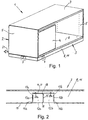
- FIG. 1 A piece of furniture according to the invention is shown with a furniture body 2 and a bottom skirting board 3.
- the furniture 1 is box-like, the furniture body 2 having a front wall 4, two side walls 5, a bottom 6, an upper wall 7 and one in Figure 1 has hidden rear wall.
- the furniture body 2 is largely open on its front.
- the type, shape and functionality of the furniture 1 can, however, be varied within the scope of the present invention and are in no way limited to the exemplary embodiment shown.
- the skirting board 3 which is preferably completely circumferential in the edge region of the base 6, consists at least predominantly of a metal sheet.
- the skirting board 3 can be designed in such a way that it supports the furniture body 2, or, if the furniture body 2 rests on separate feet (not shown), it can only be a base panel without a supporting function.
- skirting boards are understood to mean both supporting skirting boards and non-supporting skirting boards.
- the skirting board 3 has a vertical skirting board wall 8, which consists of a material that can be deformed by bending.
- the skirting board wall 8 expediently consists of a metal sheet.
- the skirting board wall 8 has a section 9 on each side of the furniture 1, which section is intended to form a cable bushing 10. These sections 9 can be arranged on each side of the furniture 1 or only on certain sides, in particular on the back of the furniture 1. Furthermore, it is also readily possible for a plurality of sections 9 to be provided on one or more sides of the furniture 1. Furthermore, it is also possible that such sections 9 are not provided or not only in the skirting board wall 8, but in another wall of the furniture 1 if this wall consists of a material that can be deformed by bending. Such a wall, in particular the skirting board wall 8, is therefore more generally referred to below as a furniture wall 11.
- Figure 2 shows a section of the skirting board 3 in isolation in the area of a section 9, which is intended to form a cable bushing 10.
- the section 9 comprises two bending tabs 12a, 12b, which are each formed by a partially cut-out section of the furniture wall 11.
- the bending tabs 12a, 12b are each separated from the adjacent edge regions of the furniture wall 11 by a vertical longitudinal slot 13a, 13b located on the outside and by an upper, continuous, horizontal longitudinal slot 14 over the majority of their circumferences.
- the two adjacent bending tabs 12a, 12b are separated from one another by a central vertical longitudinal slot 15 over the major part of their height.
- the lateral vertical longitudinal slots 13a, 13b have a length such that between the lower end of the vertical longitudinal slots 13a, 13b and the lower one Edge of the bending tabs 12a, 12b only a relatively narrow bridge section 16a, 16b or web is present. There is only a narrow bridge section 17a, 17b or web between the upper end of the vertical longitudinal slots 13a, 13b and the horizontal longitudinal slot 14.
- the two bending tabs 12a, 12b in the in Figure 2 Starting position shown, in which they are aligned with the adjacent areas of the furniture wall 11, connected to one another by upper and lower connecting sections 18, which extend from the upper end of the central vertical longitudinal slot 15 to the horizontal longitudinal slot 15 and from the lower end of the central vertical longitudinal slot 15 to extend to the lower edge of the bending tabs 12a, 12b.
- These connecting sections 18 form a predetermined dividing line and can be designed such that they can be severed in a simple manner, for example by having a smaller wall thickness than the bending tabs 12a, 12b.
- the longitudinal slots 13a, 13b, 14 are expediently formed by punching out the continuous furniture wall 11 which is flat in the initial state.
- the bending tabs 12a, 12b Due to the longitudinal slots 13a, 13b, 14 it is possible, after severing the connecting sections 18, to bend the bending tabs 12a, 12b inwards in a simple manner, the bending tabs being pivoted about the vertical pivot axes lying in the region of the vertical longitudinal slots 13a, 13b and the bridge sections 16a, 17a and 16b, 17b are bent accordingly.
- the bending flaps 12a, 12b are expediently bent inwards in such a way that they are arranged at an angle of 90 ° to the adjacent areas of the furniture wall 11.
- the bending tabs 12a, 12b are square or rectangular in shape and, in the exemplary embodiment shown, extend from the lower edge 19 of the skirting board 3 over most of the height of the skirting board 3. However, the height and width of the bending tabs 12a, 12b can vary widely.
- a cable bushing 10 ( Figure 5 ) are installed in order to lead a cable 21 through the baseboard 3, the connecting sections 18 are severed, for example by means of a saw or sheet metal shears, as a result of which the bending tabs 12a, 12b can be bent inwards.
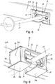
- Figure 3 shows the bending tabs 12a, 12b in their inwardly bent open position, in which they are opened like a door leaf. In this open position, the bending tabs 12a, 12b laterally delimit a wall opening 20 in the baseboard 3.
- This wall opening 20 is used to insert a sleeve-shaped plug-in frame that lines the wall opening 20.
- the plug-in frame 22 expediently consists of a one-piece plastic part. Other materials and a plug-in frame 22 composed of several parts are also possible.
- the plug-in frame 22 comprises side walls 23, a bottom 24, a top wall 25 and an outer end wall 26 which projects laterally and upwards over the side walls 23 and top wall 25.
- the width of the plug-in frame 22 is dimensioned in the region of the side walls 23 such that when the plug-in frame 22 is inserted into the wall opening 20, they rest on the bent bending tabs 12a, 12b.
- the insertion frame 22 also has, as from the Figures 3 and 4 It can be seen that upper webs 27 and lower webs 28 project laterally outwards over the side walls 23.
- the upper webs 27 are formed by a lateral extension of the ceiling wall 25, while the lower webs 28 are formed by a lateral extension of the bottom 24.
- the webs 27, 28 expediently extend over the entire depth or at least over the major part of the depth of the insertion frame 22, as a result of which a particularly good support effect can be achieved.
- an intermediate space 30 is formed which, after the bending of the bending flaps 12a, 12b, lateral grooves 31a, 31b ( Figure 3 ) between the upper bridge sections 17a, 17b and the upper edge 32 of the wall opening.
- the upper webs 27 of the plug-in frame 22 engage in these lateral grooves 31a, 31b.
- the lower webs 28 of the insertion frame 22 engage under the bending tabs 12a, 12b.
- the bending tabs 12a, 12b thus support the insertion frame 22 upwards and downwards, which contributes significantly to a firm, reliable fit of the insertion frame 22 within the wall opening 20.
- the width of the bending tabs 12a, 12b and the depth of the insertion frame 22 are expediently coordinated with one another in such a way that the bent bending tabs 12a, 12b extend at least over the vast majority of the depth of the insertion frame 22.
- the insert frame 22 is inserted into the wall opening 22 until the end wall 26 strikes the outside of the furniture wall 11.
- the end wall 26 thus protrudes over the edge of the wall opening 20 and forms an outer stop to limit the insertion path of the plug-in frame 22.
- a retaining projection 33 is formed on the top wall 25 of the plug-in frame 22, which in the inserted state of the plug-in frame 22 has the furniture wall 11 in this way engages behind that a displacement of the insertion frame 22 against the insertion direction is prevented.
- the retaining projection 33 is wedge-shaped with a run-on slope.
- the retaining projection 33 is arranged centrally on the plug-in frame 22.
- Other designs of the retaining projection 33 are readily possible, for example stable but resilient spring tongues.
- two or more retaining projections can also be provided, which are arranged distributed over the width of the plug-in frame 22.
- the plug-in frame 22 can be clipped into the skirting board 3 without tools and, since it is supported laterally on the furniture wall 11 between the front end wall 26 and the retaining projection 33 and additionally by the bending tabs 12a, 12b, is held firmly and reliably on the skirting board 3.
- the bottom 24 of the plug-in frame 22 is divided into two bottom sections 24a, 24b, which extend from the side walls 23 towards one another. However, the bottom sections 24a, 24b are spaced apart from one another, so that a gap 34 is formed in the middle of the plug-in frame 22 and is only bridged by a bridge element 35 with a reduced wall thickness.
- the bridge element 35 is designed in such a way that it can be severed in a simple manner in order, if necessary, to insert the cable 21 from below through the gap 34 into a cable passage space 36 enclosed by the plug-in frame 22. If it is not necessary to cut through the bridge element 35, since the plug-in frame 22 is of sufficiently large dimensions, the bridge element 35 stabilizes the base 24, since the plug-in frame 22 is then designed to be closed all around in the circumferential direction.
- the plug-in frame 22 is used to hold and hold a cable strain relief device 37, which in Figure 3 in exploded view and in the Figures 4 until 6 is shown in the assembled state.
- the cable strain relief device 37 comprises an upper part 38 and a lower part 39.
- Upper part 38 and lower part 39 consist of two separate components which can be detached from one another and connected to one another by means of a screw 40.
- the upper part 38 and lower part 39 are each bowl-shaped.
- semicircular cutouts 41, 42 are provided, which, when the upper part 38 and lower part 39 are assembled, form circular cutouts in order to receive and clamp cables 21 therein.
- the cable strain relief device 37 is designed to receive and clamp three cables arranged next to one another.
- the number of cable passages per cable strain relief device is variable and can also comprise only one or two cable passages or more than three cable passages. If the upper part 38 and lower part 39 are screwed together by means of the screw 40, the cable 21 passed through is firmly clamped inside the cable strain relief device 37, ie the cable strain relief device 37 is then firmly anchored to the cable 21.
- the cable strain relief device 37 has essentially the shape of a cuboid, the top wall 43 of the upper part 38 and the bottom 44 of the lower part 39 being flat.
- the cable strain relief device 37 is only positive and in the illustrated embodiment can be anchored without tools within the plug-in frame 22.
- the interlocking connection between the plug-in frame 22 and the cable strain relief device 37 comprises vertical webs 45 on the plug-in frame side, which protrude inwards from the side walls 23 of the plug-in frame 22.
- two mutually parallel webs 45 are provided on each side wall 23.
- the number of webs 45 can vary and, for example, can also be only one web 45 or three webs 45 per side wall 23.
- the webs 45 extend as from Figure 3 can be seen down to the bottom portions 24a, 24b. In contrast, the webs 45 do not extend all the way up to the ceiling wall 25, but are at a distance from this. This distance is dimensioned such that it is slightly larger than the thickness of lateral retaining strips 46 which are provided in the side regions of the upper part 38 of the cable strain relief device 37.
- these holding strips 46 are formed by a lateral extension of the top wall 43 of the upper part 38, which project laterally outwards via the side walls 47 of the upper part 38.
- Two guide grooves 48 are provided in each of the lateral holding strips 46, which are adapted to the webs 45 of the plug-in frame 22. Due to this design, the cable strain relief device 37 can be inserted into the insertion frame 22 in an elevated position, in which it is located directly below the ceiling wall 25 of the insertion frame 22, until the guide grooves 48 are aligned with the webs 45.
- the sections 9 of the skirting board 3 thus form, with the plug-in frame 22 and the cable strain relief device 37, a cable bushing 10 for the skirting board 3, which, after the bending flaps 12a, 12b have been bent over, enables the cable strain relief device 37 to be simply, securely and without tools on the skirting board 3.
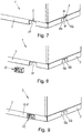
- a piece of furniture 1 is initially provided with a baseboard 3, which preferably has a plurality of partially free-cut sections 9 provided at different locations on the baseboard 3 for the formation of a cable duct 10.
- the right section 9 is shown in the initial state, in which the bending tabs 12a, 12b are aligned with the adjoining skirting board wall 8 or furniture wall 11.
- the left section 9, however, is shown in a state in which the bending tabs 12a, 12b are bent inwards transversely to the skirting board wall 8 or furniture wall 11, as a result of which a wall opening 20 is created in the skirting board 3.
- the connecting sections 18 between the bending tabs 12a, 12b are severed.
- the plug-in frame 22 is guided from the outside, for example from the rear of the furniture 1, to the wall opening 20 and inserted into the latter until the end wall 26 of the plug-in frame 22 on the skirting board wall 8 / furniture wall 11 abuts and the retaining projection 33 hits the adjacent area of the skirting board wall 8 / furniture wall 11.
- the plug-in frame 22 is brought into holding engagement with the edge region of the skirting board wall 8 / furniture wall 11 surrounding the plug-in frame 22 and with the bending tabs 12a, 12b.
- the cable 21 passed through the insertion frame 22. If the cable 21 does not have an end part that is larger than the inner passage width of the plug-in frame 22, it is not necessary to cut the bridge element 35 between the bottom sections 24a, 24b. Otherwise, the bridge part 35 is separated or removed in order to be able to pass the cable 21 between the bottom sections 24a, 24b.
- the cable strain relief device 37 can now be inserted into the plug-in frame 22 and anchored in this in a form-fitting manner.
- the insertion takes place in a raised position of the cable strain relief device 37 relative to the plug-in frame 22. If the cable strain relief device 37 is subsequently moved downward within the plug-in frame 22, the form-fitting connection elements of the cable strain-relief device 37 interact with the form-fitting connection elements of the plug-in frame 22 which are matched thereto such that a movement of the Cable strain relief device 37 and thus the cable 21 is blocked in the longitudinal direction of the cable passage space 36.
- the interlocking locking device between cable strain relief device 37 and plug-in frame 22 can also be implemented in another way.
- the cable strain relief device 37 it is possible to design the cable strain relief device 37 as a rotating body with outer locking pins that can be inserted into the plug-in frame 22 in a first rotational position and, after turning the cable strain relief device 37, engage in a groove that is arranged in a peripheral wall of the plug-in frame 22.
- the webs 45 can also be arranged on the cable strain relief device 37 and the guide grooves 48 on the plug-in frame 22.
Landscapes
- Installation Of Indoor Wiring (AREA)
Claims (12)
- Meuble présentant une traversée de câble (10) qui est prévue dans une paroi (11) du meuble, en particulier dans une paroi de plinthe (8), comportant les éléments suivants :- la paroi de meuble (11) présente une ouverture de paroi (20) qui est délimitée latéralement par au moins une languette flexible (12a, 12b) qui est formée par une portion (9) de la paroi de meuble (11) dégagée partiellement,- un cadre d'enfichage (22) délimitant un espace de passage de câble (36) est disposé à l'intérieur de l'ouverture de paroi (20), cadre qui est en engagement de retenue avec une zone de bord de la paroi de meuble (11) délimitant l'ouverture de paroi (20) et avec la languette flexible (12a, 12b),- un moyen de décharge de traction de câble (37) peut être fixé à l'intérieur du cadre d'enfichage (22), qui est réalisé pour coincer un câble (21),- le cadre d'enfichage (22) et le moyen de décharge de traction de câble (37) présentent un moyen de liaison par coopération de forme qui est réalisé de telle sorte que le moyen de décharge de traction de câble (37) et le cadre d'enfichage (22) peuvent être amenés en engagement de retenue mutuel par coopération de forme par déplacement ou rotation du moyen de décharge de traction de câble (37) à l'intérieur du cadre d'enfichage (22), de telle sorte qu'un mouvement du moyen de décharge de traction de câble (37) le long de l'espace de passage de câble (36) est bloqué.
- Meuble selon la revendication 1,
caractérisé en ce que
l'ouverture de paroi (20) est délimitée latéralement par deux languettes flexibles (12a, 12b) qui sont formées par deux portions de paroi juxtaposées de la paroi de meuble (11), qui sont réalisées à la manière des battants d'une porte et qui peuvent être fléchies depuis une position de départ fermée dans laquelle ils se situent dans un plan principal de la paroi de meuble (11), jusque dans une position d'ouverture. - Meuble selon la revendication 2,
caractérisé en ce que
dans leur position de départ, les languettes flexibles (12a, 12b) sont reliées l'une à l'autre au moyen d'au moins une portion de liaison (18) séparable. - Meuble selon l'une des revendications précédentes,
caractérisé en ce que
les languettes flexibles (12a, 12b) sont reliées à la paroi de meuble (11) adjacente uniquement par au moins une portion formant pont (16a, 17a ; 16b, 17b) légèrement flexible qui se trouve dans une zone de bord latéralement extérieure des languettes flexibles (12a, 12b). - Meuble selon l'une des revendications précédentes,
caractérisé en ce que
le cadre d'enfichage (22) comprend des barrettes (27, 28) latéralement saillantes qui sont réalisées pour engager par le dessus et par le dessous les languettes flexibles (12a, 12b) situées en position d'ouverture. - Meuble selon la revendication 5,
caractérisé en ce que
les languettes flexibles (12a, 12b) ont un bord supérieur (29a, 29b) qui est espacé de la paroi de meuble (11) adjacente en direction verticale de manière à former un espace intermédiaire (30) jusque dans lequel peuvent s'étendre des barrettes (27) latéralement saillantes du cadre d'enfichage (22). - Meuble selon l'une des revendications précédentes,
caractérisé en ce que
le cadre d'enfichage (22) comprend une butée extérieure qui, dans l'état enfiché du cadre d'enfichage (22), s'appuie contre la face extérieure de la paroi de meuble (11), et au moins une saillie de retenue (33) qui, dans l'état enfiché du cadre d'enfichage (22), engage par l'arrière la paroi de meuble (11) de manière à empêcher un déplacement en sens opposé à la direction d'enfichage. - Meuble selon l'une des revendications précédentes,
caractérisé en ce que
le cadre d'enfichage (22) présente du côté fond une fente (34) ou un élément formant pont (35) ayant un emplacement destiné à la séparation pour former une fente (34) permettant d'insérer un câble (21) dans le cadre d'enfichage (22). - Meuble selon l'une des revendications précédentes,
caractérisé en ce que
le moyen de liaison par coopération de forme comprend des barrettes (45) qui font saillie des parois latérales (23) du cadre d'enfichage (22) jusque dans l'espace de passage de câble (36), ainsi que des rainures (48) qui sont disposées au niveau du moyen de décharge de traction de câble (37) et qui peuvent être amenées en engagement avec les barrettes (45). - Meuble selon la revendication 9,
caractérisé en ce que
les barrettes (45) sont constituées par des barrettes verticales (45) ayant une extrémité supérieure qui est espacée de la paroi de plafond (25) du cadre d'enfichage (22), de sorte qu'une fente d'insertion existe entre la barrette (45) et la paroi de plafond (25), et en ce que des baguettes de retenue latérales (46) existent au niveau du moyen de décharge de traction de câble dans lesquelles sont prévues les rainures (48) réalisées pour l'engagement de retenue avec les barrettes (45). - Meuble selon la revendication 10,
caractérisé en ce que
le moyen de décharge de traction de câble (37) comprend une partie supérieure (38) et une partie inférieure (39) entre lesquelles peut être coincé au moins un câble (21), la partie supérieure (38) comprenant des parois latérales (47) et une paroi de plafond (43) en forme de plaque qui fait saillie latéralement au-delà des parois latérales (47) et qui constitue les baguettes de retenue (46). - Procédé pour réaliser une traversée de câble (10) ayant un moyen de décharge de traction de câble (37) dans une paroi de meuble (11), en particulier dans une paroi de plinthe (8) de meubles (1),
caractérisé par les étapes suivantes consistant à :- fournir un meuble (1) ayant une paroi de meuble (11) qui comprend au moins une languette flexible (12a, 12b) qui est partiellement séparée de la paroi de meuble (11) adjacente ou qui est partiellement séparable par des emplacements définis destinés à la séparation,- fléchir la languette flexible (12a, 12b) dans une position d'ouverture coudée par rapport à la paroi de meuble (11) adjacente, afin de former une ouverture de paroi (20) dans la paroi de meuble (11),- enficher un cadre d'enfichage (22) dans l'ouverture de paroi (20), le cadre d'enfichage (22) étant amené en engagement de retenue avec une zone de bord de la paroi de meuble (11) délimitant l'ouverture de paroi (20) et avec ladite au moins une languette flexible (12a, 12b),- coincer un câble (21) sur ou dans un moyen de décharge de traction de câble (37) à l'extérieur du cadre d'enfichage (22),- insérer le moyen de décharge de traction de câble (37) dans le cadre d'enfichage (22),- ancrer le moyen de décharge de traction de câble (37) à l'intérieur du cadre d'enfichage (22) par déplacement ou rotation du moyen de décharge de traction de câble (37) de manière à amener en engagement de retenue par coopération de forme le moyen de décharge de traction de câble (37) avec le cadre d'enfichage (22).
Applications Claiming Priority (1)
| Application Number | Priority Date | Filing Date | Title |
|---|---|---|---|
| PCT/IB2017/001093 WO2019048897A1 (fr) | 2017-09-08 | 2017-09-08 | Meuble doté d'une traversée de câble et procédé de formation d'une traversée de câble |
Publications (2)
| Publication Number | Publication Date |
|---|---|
| EP3558058A1 EP3558058A1 (fr) | 2019-10-30 |
| EP3558058B1 true EP3558058B1 (fr) | 2020-04-22 |
Family
ID=60153359
Family Applications (1)
| Application Number | Title | Priority Date | Filing Date |
|---|---|---|---|
| EP17787608.3A Active EP3558058B1 (fr) | 2017-09-08 | 2017-09-08 | Meuble doté d'une traversée de câble et procédé de formation d'une traversée de câble |
Country Status (3)
| Country | Link |
|---|---|
| EP (1) | EP3558058B1 (fr) |
| ES (1) | ES2796104T3 (fr) |
| WO (1) | WO2019048897A1 (fr) |
Family Cites Families (3)
| Publication number | Priority date | Publication date | Assignee | Title |
|---|---|---|---|---|
| DE8517395U1 (de) * | 1985-06-14 | 1985-08-08 | König & Neurath KG, 6367 Karben | Kabelzugentlastungshalter |
| JPH1156482A (ja) * | 1997-08-19 | 1999-03-02 | Kurogane Kosakusho Ltd | 学習机 |
| US6133528A (en) * | 1997-09-09 | 2000-10-17 | Kimball International, Inc. | Cable management grommet |
-
2017
- 2017-09-08 WO PCT/IB2017/001093 patent/WO2019048897A1/fr unknown
- 2017-09-08 EP EP17787608.3A patent/EP3558058B1/fr active Active
- 2017-09-08 ES ES17787608T patent/ES2796104T3/es active Active
Non-Patent Citations (1)
| Title |
|---|
| None * |
Also Published As
| Publication number | Publication date |
|---|---|
| ES2796104T3 (es) | 2020-11-25 |
| WO2019048897A1 (fr) | 2019-03-14 |
| EP3558058A1 (fr) | 2019-10-30 |
Similar Documents
| Publication | Publication Date | Title |
|---|---|---|
| EP0939984B1 (fr) | Armoire de distribution | |
| DE2314330C2 (de) | Elektrischer Verbinder | |
| EP1956684A2 (fr) | Contact universel | |
| EP3281240B1 (fr) | Rack pour recevoir des éléments de stockage d'énergie électrique, comprenant les piles et un arrangement associé | |
| EP3843221A1 (fr) | Cadre de support pour un connecteur | |
| DE202010008762U1 (de) | Elektrische Anschlussvorrichtung | |
| DE102007059204A1 (de) | Schaltschrank oder Rack | |
| EP3016215A1 (fr) | Dispositif de mise a la terre de rails | |
| DE102012021835A1 (de) | Gleitführungselement und Tischplattenbefestigungssystem zur verschiebbaren Befestigung einer Tischplatte | |
| WO2019020386A1 (fr) | Dispositif de logement d'un objet dans un véhicule à moteur | |
| EP3558058B1 (fr) | Meuble doté d'une traversée de câble et procédé de formation d'une traversée de câble | |
| EP2192665B1 (fr) | Cassette d'installation au sol pour appareils d'installation électriques | |
| EP3731358B1 (fr) | Prise d'installation et agencement de prise d'installation doté d'une telle prise d'installation | |
| EP3026350B1 (fr) | Hotte aspirante dotée d'un composant | |
| EP3071896B1 (fr) | Support de montage pour une enceinte et méthode de monter une enceinte utilisant ledit support | |
| DE202013102648U1 (de) | Gehäuse zum Aufnehmen von Bauteilen, insbesondere von elektronischen Baugruppen, Bauelementen und dergleichen | |
| DE19846577C2 (de) | Elektrisches Gerät mit einem Verbindungsclip und einer Verbindungsclipaufnahme zur Verbindung mit einem zweiten elektrischen Gerät | |
| DE4420674A1 (de) | Befestigungsklemmvorrichtung für einen Steckerrahmen | |
| DE102004013010B3 (de) | Vorrichtung zur Aufnahme von länglichen Gegenständen | |
| DE10328407A1 (de) | Sockelanordnung für einen elektrischen Schaltschrank | |
| WO2013143930A1 (fr) | Module de système destiné au génie électrique d'immeubles et au génie des systèmes portiers de communication | |
| DE102004059815B4 (de) | Montageträger für Unterflurdose | |
| DE2201883A1 (de) | Kontaktbuchse fuer elektrische installationsgeraete | |
| AT522412B1 (de) | Installationsdose und Installationsdosenanordnung mit einer solchen Installationsdose | |
| DE19546779C1 (de) | Grundelement mit Aufnahmeeinrichtungen |
Legal Events
| Date | Code | Title | Description |
|---|---|---|---|
| STAA | Information on the status of an ep patent application or granted ep patent |
Free format text: STATUS: UNKNOWN |
|
| STAA | Information on the status of an ep patent application or granted ep patent |
Free format text: STATUS: THE INTERNATIONAL PUBLICATION HAS BEEN MADE |
|
| PUAI | Public reference made under article 153(3) epc to a published international application that has entered the european phase |
Free format text: ORIGINAL CODE: 0009012 |
|
| STAA | Information on the status of an ep patent application or granted ep patent |
Free format text: STATUS: REQUEST FOR EXAMINATION WAS MADE |
|
| 17P | Request for examination filed |
Effective date: 20190724 |
|
| AK | Designated contracting states |
Kind code of ref document: A1 Designated state(s): AL AT BE BG CH CY CZ DE DK EE ES FI FR GB GR HR HU IE IS IT LI LT LU LV MC MK MT NL NO PL PT RO RS SE SI SK SM TR |
|
| AX | Request for extension of the european patent |
Extension state: BA ME |
|
| GRAP | Despatch of communication of intention to grant a patent |
Free format text: ORIGINAL CODE: EPIDOSNIGR1 |
|
| STAA | Information on the status of an ep patent application or granted ep patent |
Free format text: STATUS: GRANT OF PATENT IS INTENDED |
|
| DAV | Request for validation of the european patent (deleted) | ||
| DAX | Request for extension of the european patent (deleted) | ||
| INTG | Intention to grant announced |
Effective date: 20200107 |
|
| GRAS | Grant fee paid |
Free format text: ORIGINAL CODE: EPIDOSNIGR3 |
|
| GRAA | (expected) grant |
Free format text: ORIGINAL CODE: 0009210 |
|
| STAA | Information on the status of an ep patent application or granted ep patent |
Free format text: STATUS: THE PATENT HAS BEEN GRANTED |
|
| AK | Designated contracting states |
Kind code of ref document: B1 Designated state(s): AL AT BE BG CH CY CZ DE DK EE ES FI FR GB GR HR HU IE IS IT LI LT LU LV MC MK MT NL NO PL PT RO RS SE SI SK SM TR |
|
| REG | Reference to a national code |
Ref country code: CH Ref legal event code: EP |
|
| REG | Reference to a national code |
Ref country code: IE Ref legal event code: FG4D Free format text: LANGUAGE OF EP DOCUMENT: GERMAN |
|
| REG | Reference to a national code |
Ref country code: DE Ref legal event code: R096 Ref document number: 502017004908 Country of ref document: DE |
|
| REG | Reference to a national code |
Ref country code: AT Ref legal event code: REF Ref document number: 1258925 Country of ref document: AT Kind code of ref document: T Effective date: 20200515 |
|
| REG | Reference to a national code |
Ref country code: LT Ref legal event code: MG4D |
|
| REG | Reference to a national code |
Ref country code: NL Ref legal event code: MP Effective date: 20200422 |
|
| PG25 | Lapsed in a contracting state [announced via postgrant information from national office to epo] |
Ref country code: NL Free format text: LAPSE BECAUSE OF FAILURE TO SUBMIT A TRANSLATION OF THE DESCRIPTION OR TO PAY THE FEE WITHIN THE PRESCRIBED TIME-LIMIT Effective date: 20200422 Ref country code: LT Free format text: LAPSE BECAUSE OF FAILURE TO SUBMIT A TRANSLATION OF THE DESCRIPTION OR TO PAY THE FEE WITHIN THE PRESCRIBED TIME-LIMIT Effective date: 20200422 Ref country code: FI Free format text: LAPSE BECAUSE OF FAILURE TO SUBMIT A TRANSLATION OF THE DESCRIPTION OR TO PAY THE FEE WITHIN THE PRESCRIBED TIME-LIMIT Effective date: 20200422 Ref country code: GR Free format text: LAPSE BECAUSE OF FAILURE TO SUBMIT A TRANSLATION OF THE DESCRIPTION OR TO PAY THE FEE WITHIN THE PRESCRIBED TIME-LIMIT Effective date: 20200723 Ref country code: NO Free format text: LAPSE BECAUSE OF FAILURE TO SUBMIT A TRANSLATION OF THE DESCRIPTION OR TO PAY THE FEE WITHIN THE PRESCRIBED TIME-LIMIT Effective date: 20200722 Ref country code: SE Free format text: LAPSE BECAUSE OF FAILURE TO SUBMIT A TRANSLATION OF THE DESCRIPTION OR TO PAY THE FEE WITHIN THE PRESCRIBED TIME-LIMIT Effective date: 20200422 Ref country code: IS Free format text: LAPSE BECAUSE OF FAILURE TO SUBMIT A TRANSLATION OF THE DESCRIPTION OR TO PAY THE FEE WITHIN THE PRESCRIBED TIME-LIMIT Effective date: 20200822 Ref country code: PT Free format text: LAPSE BECAUSE OF FAILURE TO SUBMIT A TRANSLATION OF THE DESCRIPTION OR TO PAY THE FEE WITHIN THE PRESCRIBED TIME-LIMIT Effective date: 20200824 |
|
| REG | Reference to a national code |
Ref country code: ES Ref legal event code: FG2A Ref document number: 2796104 Country of ref document: ES Kind code of ref document: T3 Effective date: 20201125 |
|
| PG25 | Lapsed in a contracting state [announced via postgrant information from national office to epo] |
Ref country code: LV Free format text: LAPSE BECAUSE OF FAILURE TO SUBMIT A TRANSLATION OF THE DESCRIPTION OR TO PAY THE FEE WITHIN THE PRESCRIBED TIME-LIMIT Effective date: 20200422 Ref country code: RS Free format text: LAPSE BECAUSE OF FAILURE TO SUBMIT A TRANSLATION OF THE DESCRIPTION OR TO PAY THE FEE WITHIN THE PRESCRIBED TIME-LIMIT Effective date: 20200422 Ref country code: HR Free format text: LAPSE BECAUSE OF FAILURE TO SUBMIT A TRANSLATION OF THE DESCRIPTION OR TO PAY THE FEE WITHIN THE PRESCRIBED TIME-LIMIT Effective date: 20200422 Ref country code: BG Free format text: LAPSE BECAUSE OF FAILURE TO SUBMIT A TRANSLATION OF THE DESCRIPTION OR TO PAY THE FEE WITHIN THE PRESCRIBED TIME-LIMIT Effective date: 20200722 |
|
| PG25 | Lapsed in a contracting state [announced via postgrant information from national office to epo] |
Ref country code: AL Free format text: LAPSE BECAUSE OF FAILURE TO SUBMIT A TRANSLATION OF THE DESCRIPTION OR TO PAY THE FEE WITHIN THE PRESCRIBED TIME-LIMIT Effective date: 20200422 |
|
| REG | Reference to a national code |
Ref country code: DE Ref legal event code: R097 Ref document number: 502017004908 Country of ref document: DE |
|
| PG25 | Lapsed in a contracting state [announced via postgrant information from national office to epo] |
Ref country code: CZ Free format text: LAPSE BECAUSE OF FAILURE TO SUBMIT A TRANSLATION OF THE DESCRIPTION OR TO PAY THE FEE WITHIN THE PRESCRIBED TIME-LIMIT Effective date: 20200422 Ref country code: IT Free format text: LAPSE BECAUSE OF FAILURE TO SUBMIT A TRANSLATION OF THE DESCRIPTION OR TO PAY THE FEE WITHIN THE PRESCRIBED TIME-LIMIT Effective date: 20200422 Ref country code: EE Free format text: LAPSE BECAUSE OF FAILURE TO SUBMIT A TRANSLATION OF THE DESCRIPTION OR TO PAY THE FEE WITHIN THE PRESCRIBED TIME-LIMIT Effective date: 20200422 Ref country code: SM Free format text: LAPSE BECAUSE OF FAILURE TO SUBMIT A TRANSLATION OF THE DESCRIPTION OR TO PAY THE FEE WITHIN THE PRESCRIBED TIME-LIMIT Effective date: 20200422 Ref country code: DK Free format text: LAPSE BECAUSE OF FAILURE TO SUBMIT A TRANSLATION OF THE DESCRIPTION OR TO PAY THE FEE WITHIN THE PRESCRIBED TIME-LIMIT Effective date: 20200422 Ref country code: RO Free format text: LAPSE BECAUSE OF FAILURE TO SUBMIT A TRANSLATION OF THE DESCRIPTION OR TO PAY THE FEE WITHIN THE PRESCRIBED TIME-LIMIT Effective date: 20200422 |
|
| PG25 | Lapsed in a contracting state [announced via postgrant information from national office to epo] |
Ref country code: SK Free format text: LAPSE BECAUSE OF FAILURE TO SUBMIT A TRANSLATION OF THE DESCRIPTION OR TO PAY THE FEE WITHIN THE PRESCRIBED TIME-LIMIT Effective date: 20200422 Ref country code: PL Free format text: LAPSE BECAUSE OF FAILURE TO SUBMIT A TRANSLATION OF THE DESCRIPTION OR TO PAY THE FEE WITHIN THE PRESCRIBED TIME-LIMIT Effective date: 20200422 |
|
| PLBE | No opposition filed within time limit |
Free format text: ORIGINAL CODE: 0009261 |
|
| STAA | Information on the status of an ep patent application or granted ep patent |
Free format text: STATUS: NO OPPOSITION FILED WITHIN TIME LIMIT |
|
| 26N | No opposition filed |
Effective date: 20210125 |
|
| REG | Reference to a national code |
Ref country code: CH Ref legal event code: PL |
|
| REG | Reference to a national code |
Ref country code: BE Ref legal event code: MM Effective date: 20200930 |
|
| PG25 | Lapsed in a contracting state [announced via postgrant information from national office to epo] |
Ref country code: LU Free format text: LAPSE BECAUSE OF NON-PAYMENT OF DUE FEES Effective date: 20200908 |
|
| PG25 | Lapsed in a contracting state [announced via postgrant information from national office to epo] |
Ref country code: BE Free format text: LAPSE BECAUSE OF NON-PAYMENT OF DUE FEES Effective date: 20200930 Ref country code: CH Free format text: LAPSE BECAUSE OF NON-PAYMENT OF DUE FEES Effective date: 20200930 Ref country code: LI Free format text: LAPSE BECAUSE OF NON-PAYMENT OF DUE FEES Effective date: 20200930 Ref country code: IE Free format text: LAPSE BECAUSE OF NON-PAYMENT OF DUE FEES Effective date: 20200908 |
|
| PG25 | Lapsed in a contracting state [announced via postgrant information from national office to epo] |
Ref country code: TR Free format text: LAPSE BECAUSE OF FAILURE TO SUBMIT A TRANSLATION OF THE DESCRIPTION OR TO PAY THE FEE WITHIN THE PRESCRIBED TIME-LIMIT Effective date: 20200422 Ref country code: MT Free format text: LAPSE BECAUSE OF FAILURE TO SUBMIT A TRANSLATION OF THE DESCRIPTION OR TO PAY THE FEE WITHIN THE PRESCRIBED TIME-LIMIT Effective date: 20200422 Ref country code: CY Free format text: LAPSE BECAUSE OF FAILURE TO SUBMIT A TRANSLATION OF THE DESCRIPTION OR TO PAY THE FEE WITHIN THE PRESCRIBED TIME-LIMIT Effective date: 20200422 |
|
| PG25 | Lapsed in a contracting state [announced via postgrant information from national office to epo] |
Ref country code: MK Free format text: LAPSE BECAUSE OF FAILURE TO SUBMIT A TRANSLATION OF THE DESCRIPTION OR TO PAY THE FEE WITHIN THE PRESCRIBED TIME-LIMIT Effective date: 20200422 Ref country code: MC Free format text: LAPSE BECAUSE OF FAILURE TO SUBMIT A TRANSLATION OF THE DESCRIPTION OR TO PAY THE FEE WITHIN THE PRESCRIBED TIME-LIMIT Effective date: 20200422 |
|
| PG25 | Lapsed in a contracting state [announced via postgrant information from national office to epo] |
Ref country code: SI Free format text: LAPSE BECAUSE OF FAILURE TO SUBMIT A TRANSLATION OF THE DESCRIPTION OR TO PAY THE FEE WITHIN THE PRESCRIBED TIME-LIMIT Effective date: 20200422 |
|
| PGFP | Annual fee paid to national office [announced via postgrant information from national office to epo] |
Ref country code: GB Payment date: 20230927 Year of fee payment: 7 |
|
| REG | Reference to a national code |
Ref country code: AT Ref legal event code: MM01 Ref document number: 1258925 Country of ref document: AT Kind code of ref document: T Effective date: 20220908 |
|
| PGFP | Annual fee paid to national office [announced via postgrant information from national office to epo] |
Ref country code: FR Payment date: 20230925 Year of fee payment: 7 Ref country code: DE Payment date: 20230927 Year of fee payment: 7 |
|
| PGFP | Annual fee paid to national office [announced via postgrant information from national office to epo] |
Ref country code: ES Payment date: 20231002 Year of fee payment: 7 |
|
| PG25 | Lapsed in a contracting state [announced via postgrant information from national office to epo] |
Ref country code: AT Free format text: LAPSE BECAUSE OF NON-PAYMENT OF DUE FEES Effective date: 20220908 |