EP3557687A1 - Unité de gestion de batteries et bloc-batterie l'incluant - Google Patents
Unité de gestion de batteries et bloc-batterie l'incluant Download PDFInfo
- Publication number
- EP3557687A1 EP3557687A1 EP18838249.3A EP18838249A EP3557687A1 EP 3557687 A1 EP3557687 A1 EP 3557687A1 EP 18838249 A EP18838249 A EP 18838249A EP 3557687 A1 EP3557687 A1 EP 3557687A1
- Authority
- EP
- European Patent Office
- Prior art keywords
- unit
- battery
- voltage
- battery management
- communication
- Prior art date
- Legal status (The legal status is an assumption and is not a legal conclusion. Google has not performed a legal analysis and makes no representation as to the accuracy of the status listed.)
- Granted
Links
- 238000004891 communication Methods 0.000 claims abstract description 104
- 238000001514 detection method Methods 0.000 claims abstract description 27
- 238000012360 testing method Methods 0.000 claims abstract description 21
- 238000002955 isolation Methods 0.000 claims description 56
- 238000006243 chemical reaction Methods 0.000 description 9
- 238000010586 diagram Methods 0.000 description 8
- 230000006870 function Effects 0.000 description 8
- 238000003745 diagnosis Methods 0.000 description 5
- 238000000034 method Methods 0.000 description 5
- 230000008569 process Effects 0.000 description 4
- 239000003990 capacitor Substances 0.000 description 3
- 230000008859 change Effects 0.000 description 3
- 238000007599 discharging Methods 0.000 description 3
- 230000000694 effects Effects 0.000 description 3
- 238000012986 modification Methods 0.000 description 3
- 230000004048 modification Effects 0.000 description 3
- 230000003287 optical effect Effects 0.000 description 3
- 238000012545 processing Methods 0.000 description 3
- WHXSMMKQMYFTQS-UHFFFAOYSA-N Lithium Chemical compound [Li] WHXSMMKQMYFTQS-UHFFFAOYSA-N 0.000 description 2
- PXHVJJICTQNCMI-UHFFFAOYSA-N Nickel Chemical compound [Ni] PXHVJJICTQNCMI-UHFFFAOYSA-N 0.000 description 2
- 239000002253 acid Substances 0.000 description 2
- 230000007547 defect Effects 0.000 description 2
- 229910052744 lithium Inorganic materials 0.000 description 2
- 238000004519 manufacturing process Methods 0.000 description 2
- 238000005259 measurement Methods 0.000 description 2
- 238000003860 storage Methods 0.000 description 2
- 230000004888 barrier function Effects 0.000 description 1
- 230000005540 biological transmission Effects 0.000 description 1
- OJIJEKBXJYRIBZ-UHFFFAOYSA-N cadmium nickel Chemical compound [Ni].[Cd] OJIJEKBXJYRIBZ-UHFFFAOYSA-N 0.000 description 1
- 238000011161 development Methods 0.000 description 1
- 238000004146 energy storage Methods 0.000 description 1
- 230000036541 health Effects 0.000 description 1
- 229910052739 hydrogen Inorganic materials 0.000 description 1
- 239000001257 hydrogen Substances 0.000 description 1
- 230000007257 malfunction Effects 0.000 description 1
- 230000003446 memory effect Effects 0.000 description 1
- 229910052759 nickel Inorganic materials 0.000 description 1
- QELJHCBNGDEXLD-UHFFFAOYSA-N nickel zinc Chemical compound [Ni].[Zn] QELJHCBNGDEXLD-UHFFFAOYSA-N 0.000 description 1
- 230000001151 other effect Effects 0.000 description 1
- 230000002093 peripheral effect Effects 0.000 description 1
- 238000002360 preparation method Methods 0.000 description 1
- 230000004044 response Effects 0.000 description 1
- 239000004065 semiconductor Substances 0.000 description 1
- 238000006467 substitution reaction Methods 0.000 description 1
Images


Classifications
-
- H—ELECTRICITY
- H01—ELECTRIC ELEMENTS
- H01M—PROCESSES OR MEANS, e.g. BATTERIES, FOR THE DIRECT CONVERSION OF CHEMICAL ENERGY INTO ELECTRICAL ENERGY
- H01M10/00—Secondary cells; Manufacture thereof
- H01M10/42—Methods or arrangements for servicing or maintenance of secondary cells or secondary half-cells
- H01M10/425—Structural combination with electronic components, e.g. electronic circuits integrated to the outside of the casing
-
- G—PHYSICS
- G01—MEASURING; TESTING
- G01R—MEASURING ELECTRIC VARIABLES; MEASURING MAGNETIC VARIABLES
- G01R31/00—Arrangements for testing electric properties; Arrangements for locating electric faults; Arrangements for electrical testing characterised by what is being tested not provided for elsewhere
- G01R31/36—Arrangements for testing, measuring or monitoring the electrical condition of accumulators or electric batteries, e.g. capacity or state of charge [SoC]
- G01R31/382—Arrangements for monitoring battery or accumulator variables, e.g. SoC
- G01R31/3828—Arrangements for monitoring battery or accumulator variables, e.g. SoC using current integration
- G01R31/3832—Arrangements for monitoring battery or accumulator variables, e.g. SoC using current integration without measurement of battery voltage
- G01R31/3833—Arrangements for monitoring battery or accumulator variables, e.g. SoC using current integration without measurement of battery voltage using analog integrators, e.g. coulomb-meters
-
- G—PHYSICS
- G01—MEASURING; TESTING
- G01R—MEASURING ELECTRIC VARIABLES; MEASURING MAGNETIC VARIABLES
- G01R31/00—Arrangements for testing electric properties; Arrangements for locating electric faults; Arrangements for electrical testing characterised by what is being tested not provided for elsewhere
- G01R31/36—Arrangements for testing, measuring or monitoring the electrical condition of accumulators or electric batteries, e.g. capacity or state of charge [SoC]
- G01R31/382—Arrangements for monitoring battery or accumulator variables, e.g. SoC
- G01R31/3835—Arrangements for monitoring battery or accumulator variables, e.g. SoC involving only voltage measurements
-
- G—PHYSICS
- G01—MEASURING; TESTING
- G01R—MEASURING ELECTRIC VARIABLES; MEASURING MAGNETIC VARIABLES
- G01R31/00—Arrangements for testing electric properties; Arrangements for locating electric faults; Arrangements for electrical testing characterised by what is being tested not provided for elsewhere
- G01R31/36—Arrangements for testing, measuring or monitoring the electrical condition of accumulators or electric batteries, e.g. capacity or state of charge [SoC]
- G01R31/396—Acquisition or processing of data for testing or for monitoring individual cells or groups of cells within a battery
-
- H—ELECTRICITY
- H01—ELECTRIC ELEMENTS
- H01M—PROCESSES OR MEANS, e.g. BATTERIES, FOR THE DIRECT CONVERSION OF CHEMICAL ENERGY INTO ELECTRICAL ENERGY
- H01M10/00—Secondary cells; Manufacture thereof
- H01M10/42—Methods or arrangements for servicing or maintenance of secondary cells or secondary half-cells
- H01M10/4285—Testing apparatus
-
- H—ELECTRICITY
- H01—ELECTRIC ELEMENTS
- H01M—PROCESSES OR MEANS, e.g. BATTERIES, FOR THE DIRECT CONVERSION OF CHEMICAL ENERGY INTO ELECTRICAL ENERGY
- H01M10/00—Secondary cells; Manufacture thereof
- H01M10/42—Methods or arrangements for servicing or maintenance of secondary cells or secondary half-cells
- H01M10/48—Accumulators combined with arrangements for measuring, testing or indicating the condition of cells, e.g. the level or density of the electrolyte
- H01M10/482—Accumulators combined with arrangements for measuring, testing or indicating the condition of cells, e.g. the level or density of the electrolyte for several batteries or cells simultaneously or sequentially
-
- H—ELECTRICITY
- H01—ELECTRIC ELEMENTS
- H01M—PROCESSES OR MEANS, e.g. BATTERIES, FOR THE DIRECT CONVERSION OF CHEMICAL ENERGY INTO ELECTRICAL ENERGY
- H01M50/00—Constructional details or processes of manufacture of the non-active parts of electrochemical cells other than fuel cells, e.g. hybrid cells
- H01M50/50—Current conducting connections for cells or batteries
- H01M50/569—Constructional details of current conducting connections for detecting conditions inside cells or batteries, e.g. details of voltage sensing terminals
-
- H—ELECTRICITY
- H01—ELECTRIC ELEMENTS
- H01M—PROCESSES OR MEANS, e.g. BATTERIES, FOR THE DIRECT CONVERSION OF CHEMICAL ENERGY INTO ELECTRICAL ENERGY
- H01M10/00—Secondary cells; Manufacture thereof
- H01M10/42—Methods or arrangements for servicing or maintenance of secondary cells or secondary half-cells
- H01M10/425—Structural combination with electronic components, e.g. electronic circuits integrated to the outside of the casing
- H01M2010/4271—Battery management systems including electronic circuits, e.g. control of current or voltage to keep battery in healthy state, cell balancing
-
- H—ELECTRICITY
- H01—ELECTRIC ELEMENTS
- H01M—PROCESSES OR MEANS, e.g. BATTERIES, FOR THE DIRECT CONVERSION OF CHEMICAL ENERGY INTO ELECTRICAL ENERGY
- H01M10/00—Secondary cells; Manufacture thereof
- H01M10/42—Methods or arrangements for servicing or maintenance of secondary cells or secondary half-cells
- H01M10/425—Structural combination with electronic components, e.g. electronic circuits integrated to the outside of the casing
- H01M2010/4278—Systems for data transfer from batteries, e.g. transfer of battery parameters to a controller, data transferred between battery controller and main controller
-
- H—ELECTRICITY
- H01—ELECTRIC ELEMENTS
- H01M—PROCESSES OR MEANS, e.g. BATTERIES, FOR THE DIRECT CONVERSION OF CHEMICAL ENERGY INTO ELECTRICAL ENERGY
- H01M2220/00—Batteries for particular applications
- H01M2220/20—Batteries in motive systems, e.g. vehicle, ship, plane
-
- Y—GENERAL TAGGING OF NEW TECHNOLOGICAL DEVELOPMENTS; GENERAL TAGGING OF CROSS-SECTIONAL TECHNOLOGIES SPANNING OVER SEVERAL SECTIONS OF THE IPC; TECHNICAL SUBJECTS COVERED BY FORMER USPC CROSS-REFERENCE ART COLLECTIONS [XRACs] AND DIGESTS
- Y02—TECHNOLOGIES OR APPLICATIONS FOR MITIGATION OR ADAPTATION AGAINST CLIMATE CHANGE
- Y02E—REDUCTION OF GREENHOUSE GAS [GHG] EMISSIONS, RELATED TO ENERGY GENERATION, TRANSMISSION OR DISTRIBUTION
- Y02E60/00—Enabling technologies; Technologies with a potential or indirect contribution to GHG emissions mitigation
- Y02E60/10—Energy storage using batteries
-
- Y—GENERAL TAGGING OF NEW TECHNOLOGICAL DEVELOPMENTS; GENERAL TAGGING OF CROSS-SECTIONAL TECHNOLOGIES SPANNING OVER SEVERAL SECTIONS OF THE IPC; TECHNICAL SUBJECTS COVERED BY FORMER USPC CROSS-REFERENCE ART COLLECTIONS [XRACs] AND DIGESTS
- Y02—TECHNOLOGIES OR APPLICATIONS FOR MITIGATION OR ADAPTATION AGAINST CLIMATE CHANGE
- Y02T—CLIMATE CHANGE MITIGATION TECHNOLOGIES RELATED TO TRANSPORTATION
- Y02T10/00—Road transport of goods or passengers
- Y02T10/60—Other road transportation technologies with climate change mitigation effect
- Y02T10/70—Energy storage systems for electromobility, e.g. batteries
Definitions
- the present disclosure relates to a battery management unit, and more particularly, to an apparatus for managing the state of a plurality of battery cells included in a battery module and a battery pack including the same.
- a battery pack applied to electric vehicles generally includes a plurality of battery modules connected in series and a plurality of battery management units.
- the battery management unit may be called a Battery Management Unit (BMU).
- BMU Battery Management Unit
- Each BMU monitors and controls the state of the battery module each BMU manages.
- a single master-multi slave structure is disclosed.
- the single master-multi slave structure includes a plurality of slave BMUs installed in each battery module and a master BMU to control the overall operation of the plurality of slave BMUs.
- each slave BMU monitors and controls the state of the battery module for which each slave BMU takes responsible, and the master BMU controls the operation of the plurality of slave BMUs.
- Communication between the plurality of slave BMUs and the master BMU may be made in either wired manner or wireless manner or both.
- Each slave BMU and the master BMU include a variety of circuit components and a plurality of electrical lines connecting them. Particularly, for the master BMU to normally control the operation of the plurality of slave BMUs, the premise is normal operation of each slave BMU. This is because a defect in even a single slave BMU may have a great influence on the overall performance of the battery pack.
- the present disclosure is directed to providing a battery management unit for testing the items required for normal management of each battery cell included in a battery module without a process of connecting a power source to a slave BMU by an operator manually and a battery pack including the same.
- a battery management unit is for a battery module including a plurality of battery cells.
- the battery management unit includes a sensing unit electrically connected to the plurality of battery cells, and configured to detect voltage of each of the plurality of battery cells and output a detection signal including voltage information representing the detected voltages, a first power supply unit configured to generate a first operating voltage using a module voltage of the battery module, and a communication unit which operates using the first operating voltage, the communication unit including an antenna, a wireless communication circuit and a first input port, and configured to receive the detection signal from the sensing unit through the first input port, test at least one preset item based on the detection signal, and output a RF signal indicating a result of the test through the antenna and the wireless communication circuit.
- the battery management unit may further include a second power supply unit having a power source terminal, and configured to convert a power source voltage of a power source to a second operating voltage when the power source is connected to the power source terminal, and a control unit which operates using the second operating voltage, and configured to output a control signal for controlling the sensing unit based on the detection signal.
- a second power supply unit having a power source terminal, and configured to convert a power source voltage of a power source to a second operating voltage when the power source is connected to the power source terminal
- a control unit which operates using the second operating voltage, and configured to output a control signal for controlling the sensing unit based on the detection signal.
- the battery management unit may further include an isolation unit which operates using the first operating voltage and the second operating voltage.
- the isolation unit may include a first isolation circuit configured to relay communication between the communication unit and the control unit.
- the isolation unit may further include a second isolation circuit which operates using the first operating voltage and the second operating voltage, and configured to relay communication between the sensing unit and the control unit.
- the second isolation circuit may include a number of isolation elements that is equal to or larger than a number of battery cells included in the battery module.
- the isolation element is a digital isolator, an opto coupler or a RF isolator.
- the sensing unit and the communication unit may communicate with each other via UART mode.
- sensing unit and the control unit may communicate with each other via SPI mode.
- control unit may be configured to output a switching signal to the communication unit when the second power voltage is supplied.
- the communication unit may further include a second input port, may be configured to inactivate the first input port when the switching signal is received through the second input port.
- a battery pack according to another aspect of the present disclosure includes the battery management unit.
- a wireless communication circuit included in a battery management unit it is possible to change the function of a wireless communication circuit included in a battery management unit depending on whether or not a battery pack including a battery management system is installed in a preset object (for example, an electric vehicle).
- control unit> refers to a processing unit of at least one function or operation, and this may be implemented by hardware or software alone or in combination.
- At least one of the plurality of BMUs may be a master BMU, and the others may be slave BMUs.
- FIG. 1 is a schematic diagram showing configuration of a battery management system 30 according to an embodiment of the present disclosure and a battery pack 10 including the same.
- the battery pack 10 includes a plurality of battery modules 20 and a battery management system 30.
- Each battery module 20 may include at least one battery cell 21.
- the battery management system 30 includes a plurality of slave BMUs 100 and at least one master BMU 200.
- the battery pack 10 is mounted in an electric vehicle to supply the power required to operate an electric motor of the electric vehicle.
- the battery pack 10 includes n (n is a natural number that is equal to or greater than 2) battery modules 20-1 ⁇ 20-n connected in series, each battery module 20 includes m (m is a natural number that is equal to or greater than 2) battery cells 21-1 ⁇ 21-m connected in series, and the battery management system 30 includes n slave BMUs 100-1 ⁇ 100-n and a single master BMU 200.
- the plurality of slave BMUs 100-1 ⁇ 100-n is installed such that the plurality of slave BMUs 100-1 ⁇ 100-n matches the plurality of battery modules 20-1 ⁇ 20-n included in the battery pack 10 one-to-one.
- Each of the plurality of slave BMUs 100-1 ⁇ 100-n is electrically connected to a battery module 20-j in which each of the plurality of slave BMUs 100-1 ⁇ 100-n is installed among the plurality of battery modules 20-1 ⁇ 20-n.
- j is a natural number that is equal to or greater than 1 and is equal to or less than n.
- Each of the plurality of slave BMUs 100-1 ⁇ 100-n detects the overall state (for example, voltage, current, temperature) of the battery module 20-j electrically connected to each of the plurality of slave BMUs 100-1 ⁇ 100-n, and performs a variety of control functions (for example, charging, discharging, balancing) to adjust the state of the battery module 20.
- each control function may be performed directly by the slave BMU 100 based on the state of the battery module 20, or may be performed according to the command from the master BMU 200.
- the plurality of slave BMUs 100-1 ⁇ 100-n and the master BMS 200 may be in communication connection with each other via a wired network such as Daisy Chain (DC).
- a wired network such as Daisy Chain (DC).
- FIG. 2 is a schematic diagram showing configuration of the slave BMU 100 according to an embodiment of the present disclosure
- FIG. 3 is a schematic diagram showing configuration of the cell balancing unit 150 according to an embodiment of the present disclosure.
- each slave BMU 100 may include a sensing unit 110, a first power supply unit 121 and a communication unit 130.
- Each slave BMU 100 may further includes at least one of a second power supply unit 122, an isolation unit 140, a cell balancing unit 150 and a control unit 170.
- the sensing unit 110 is configured to detect electrical parameters representing the state of the battery module 20.
- the sensing unit 110 includes a voltage measurement circuit to detect the voltage of each battery cell 21 included in the battery module 20, and optionally, may further include a temperature detection circuit to detect the temperature of the battery module 20.
- the voltage measurement circuit of the sensing unit 110 detects the voltage across each battery cell 21 using a voltage sensor 111 electrically connected to each battery cell 21 through a plurality of electrical lines, and generates voltage information representing the detected voltage.
- the temperature detection circuit of the sensing unit 110 detects the temperature of the battery module 20 or at least one battery cell 21 included in the battery module 20 using a temperature sensor 112 disposed in the battery module 20 or at a predetermined distance from the battery module 20, and generates temperature information representing the detected temperature.
- the sensing unit 110 outputs a detection signal including at least one of the voltage information and the temperature information.
- the detection signal outputted by the sensing unit 110 may be received by the communication unit 130.
- the sensing unit 110 and the communication unit 130 may communicate with each other through one of serial communication modes, for example, Universal Asynchronous Receiver Transmitter (UART) mode.
- UART Universal Asynchronous Receiver Transmitter
- the first power supply unit 121 may include a device capable of DC-DC voltage conversion, for example, a voltage conversion circuit including at least one of a Low Drop Out (LDO) regulator, a linear regulator and a Switched Mode Power Supply (SMPS).
- LDO Low Drop Out
- SMPS Switched Mode Power Supply
- the first power supply unit 121 When electrical energy is supplied from the battery module 20, the first power supply unit 121 generates at least one preset operating voltage from the module voltage across the battery module 20 using the voltage conversion circuit. Subsequently, the first power supply unit 121 supplies the operating voltage to other circuits and/or elements included in the slave BMU 100.
- LDO Low Drop Out
- SMPS Switched Mode Power Supply
- the first power supply unit 121 may supply the same level of operating voltage to the sensing unit 110, the communication unit 130, the isolation unit 140 and the cell balancing unit 150.
- the first power supply unit 121 may supply, to one of the sensing unit 110, the communication unit 130, the isolation unit 140 and the cell balancing unit 150, operating voltage (for example, 5.0V) of different level from the operating voltage (for example, 3.3V) supplied to one of the others.
- At least one of the sensing unit 110, the communication unit 130, the isolation unit 140 and the cell balancing unit 150 may convert the module voltage of the battery module 20 to operating voltage required for the operation thereof using a voltage conversion circuit provided therein, not the operating voltage supplied by the first power supply unit 121.
- the communication unit 130 includes an antenna 131, a wireless communication circuit 132 and a wired communication circuit 133 operably connected to each other, and is configured to operate using the operating voltage supplied from the first power supply unit 121.
- the communication unit 130 includes a first input port IN1 electrically connected to the sensing unit 110 through the electrical line, and receives the detection signal from the sensing unit 110 through the first input port IN1.
- the communication unit 130 may further include a second input port IN2.
- the communication unit 130 may further include a first output port OUT1 electrically connected to the sensing unit 110 through the electrical line, and may transmit a control signal requesting the transmission of the detection signal to the sensing unit 110 through the first output port OUT1.
- the wireless communication circuit 132 may include a wireless transceiver 132a and a Micro Control Unit (MCU) 132b.
- the wireless transceiver 132a and the MCU 132b may be implemented as a semiconductor integrated into a single chip, and this may be called 'RF(Radio Frequency)-SoC(System on Chip)'.
- the MCU 132b may test at least one item related to the battery module 20 based on the detection signal from the sensing unit 110 while the control unit 170 as described below is in an inactive state (i.e., power source voltage is not supplied).
- the at least one item to test may include a failure in the sensing unit 110 or a failure in the cell balancing unit 150.
- the MCU 132b transmits the test result information indicating the result of the test performed by the MCU 132b to the wireless transceiver 132a.
- the wireless transceiver 132a may transmit a RF signal including the test result information from the MCU 132b to an operator terminal 2 or the master BMU 200 through the antenna 131.
- the wireless communication circuit 132 may demodulate the wireless signal received by the antenna 131.
- the wireless signal received by the antenna 131 may be transmitted from the outside, for example, the master BMU 200 or other slave BMU 100.
- the wired communication circuit 133 is electrically connected to the first input port IN1 and the first output port OUT1 to support a wired communication between the communication unit 130 and the sensing unit 110.
- the second power supply unit 122 includes a voltage conversion circuit connected to a power source terminal P provided in the slave BMU 100 including the second power supply unit 122.
- the voltage conversion circuit of the second power supply unit 122 may include a device capable of DC-DC voltage conversion, for example, at least one of a LDO regulator, a linear regulator and an SMPS.
- the second power supply unit 122 When the power source B AUX1 (for example, a lead-acid battery of an electric vehicle) is connected to the power source terminal P, the second power supply unit 122 is configured to convert the power source voltage of the power source B AUX1 to at least one preset operating voltage using the voltage conversion circuit of the second power supply unit 122. Subsequently, the second power supply unit 122 supplies the operating voltage to other circuits or elements included in the slave BMU 100.
- the power source B AUX1 for example, a lead-acid battery of an electric vehicle
- the second power supply unit 122 may supply the same level of operating voltage to the isolation unit 140 and the control unit 170.
- the second power supply unit 122 may supply, to one of the isolation unit 140 and the control unit 170, operating voltage (for example, 5.0V) of different level from the operating voltage (for example, 3.3V) supplied to the other.
- control unit 170 may convert the power source voltage to another operating voltage required for the operation thereof using a voltage conversion circuit provided therein, rather than the operating voltage supplied by the second power supply unit 122.
- the isolation unit 140 is configured to operate using the operating voltage supplied from the first power supply unit 121 and the operating voltage supplied from the second power supply unit 122.
- the isolation unit 140 supports communication between the components belonging to high voltage domain and the components belonging to low voltage domain while maintaining the electrical isolation between high voltage domain and low voltage domain of the slave BMU 100.
- 'high voltage domain' may refer to a part that is electrically connected to the battery module 20 and operates on the electrical energy supplied from the battery module 20.
- the sensing unit 110, the first power supply unit 121 and the communication unit 130 belong to the high voltage domain.
- 'Low voltage domain' may refer to the remaining part of the slave BMU 100 except the high voltage domain.
- the second power supply unit 122 and the control unit 170 belong to the low voltage domain.
- the isolation unit 140 includes a first isolation circuit 141.
- the first isolation circuit 141 relays communication between the communication unit 130 and the control unit 170 using the operating voltage supplied form the first power supply unit 121 and the operating voltage supplied from the second power supply unit 122. That is, the signal from the communication unit 130 is transmitted to the control unit 170 through the first isolation circuit 141, and the signal from the control unit 170 is transmitted to the communication unit 130 through the first isolation circuit 141.
- the isolation unit 140 may further include a second isolation circuit 142.
- the second isolation circuit 142 relays communication between the sensing unit 110 and the control unit 170 using the operating voltage supplied from the first power supply unit 121 and the operating voltage supplied from the second power supply unit 122. Additionally, the second isolation circuit 142 may relay communication between the cell balancing unit 150 and the control unit 170.
- Each of the first isolation circuit 141 and the second isolation circuit includes at least one isolation element.
- the isolation element includes a transmitter and a receiver, and may be a digital isolator, an opto coupler or a RF isolator with an isolation barrier between the input side and the output side.
- the transmitter may be a light source such as a LED
- the receiver may be an optical detector such as a photo diode.
- the transmitter may be RF XMTR
- the receiver may be RF RCVR.
- One of the transmitter and the receiver of the isolation element may be electrically connected to the high voltage domain side, while the other may be electrically connected to the low voltage domain side.
- the second isolation circuit 142 may include the number of isolation elements that is equal to or larger than the number of battery cells 21 included in the battery module 20.
- the second isolation circuit 142 may include at least m+1 isolation elements.
- m isolation elements transmit a signal representing the voltage of each of m battery cells 21 outputted by the sensing unit 110 to the control unit 170.
- One remaining isolation element transmits a control signal outputted by the control unit 170 to the sensing unit 110.
- the cell balancing unit 150 is configured to selectively perform cell balancing of each of the plurality of battery cells 21 included in each battery module 20 in response to the balancing command from the communication unit 130 or the control unit 170.
- the cell balancing unit 150 performs cell balancing. For example, the cell balancing unit 150 discharges the battery cell 21 having higher remaining capacity than the other battery cell 21 among the plurality of battery cells 21-1 ⁇ 21-m included in the common battery module 20 to equalize the remaining capacity between the plurality of battery cells 21-1 ⁇ 21-m included in the common battery module 20.
- the cell balancing unit 150 includes a plurality of balancing resistors R C and a plurality of balancing switches SW.
- a series circuit including one balancing resistor R C and one balancing switch SW is connected between two ends of each battery cell 21. Accordingly, the number of battery cells 21 per the battery module 20 may be equal to the number of balancing resistors R C and the number of balancing switches SW included in each cell balancing unit 150.
- the balancing switch SW connected between two ends of the battery cell 21-j is turned on, and electrical energy of the battery cell 21 is consumed by the balancing resistor Rc.
- the cell balancing unit 150 may further include a plurality of diagnosis resistors R a , a plurality of protection resistors R b and/or a plurality of protection capacitors C.
- the plurality of diagnosis resistors R a is used to detect a failure in the cell balancing unit 150.
- One diagnosis resistor R a is connected to each electrode of each battery cell 21.
- the failure in the cell balancing unit 150 may be, for example, disconnection of the electrical line connecting each battery cell 21 and the cell balancing unit 150 or malfunction of the balancing switch SW. Referring to FIG. 3 , adjacent two battery cells 21 are connected to a diagnosis resistor R a together, and thus the cell balancing unit 150 may include a total of m+1 diagnosis resistors R a .
- the plurality of protection resistors R b prevents overcurrent from flowing in the sensing unit 110.
- One protection resistor R b is connected to each end of each series circuit. Accordingly, the cell balancing unit 150 may include a total of m+1 protection resistors R b .
- the plurality of protection capacitors C acts as a RC filter together with the plurality of protection resistors R b .
- the RC filter is used to filter off noise (for example, sharp change in current) entering the sensing unit 110 through the cell balancing unit 150.
- Each protection capacitor C is connected to each battery cell 21 in parallel, and thus the cell balancing unit 150 may include a total of m protection resistors R b .
- the wireless communication circuit 132 may output a control signal to turn on or off each balancing switch SW included in the cell balancing unit 150, and receive the detection signal outputted by the sensing unit 110.
- each balancing switch SW When each balancing switch SW is turned on or off, the voltage of each battery cell 21 indicated by the detection signal outputted by the sensing unit 110 may change. Accordingly, the MCU 132b of the wireless communication circuit 132 may conduct a test to determine a failure in each balancing switch SW or disconnection of the electrical line in the cell balancing unit 150 based on the detection signal.
- the control unit 170 includes at least one processor that operates using the power source voltage supplied from the second power supply unit 122 and a memory 171.
- the memory 171 may be included in the control unit 170.
- the control unit 170 may be operably connected to the communication unit 130 through the first isolation circuit 141, and may be operably connected to the sensing unit 110 through the second isolation circuit 142. When the power source voltage is supplied, the control unit 170 is configured to manage the overall operation of the slave BMU 100 including the control unit 170.
- control unit 170 may output a control signal for controlling the sensing unit 110 based on the detection signal received from the sensing unit 110 through the second isolation circuit 142.
- the control signal outputted to control the sensing unit 110 is transmitted to the sensing unit 110 through the second isolation circuit 142.
- the control unit 170 may communicate with the sensing unit 110 through one of serial communication modes, for example Serial Peripheral Interface (SPI) mode.
- SPI Serial Peripheral Interface
- Each processor included in the control unit 170 may selectively include a processor, an application-specific integrated circuit (ASIC), a chipset, a logic circuit, a register, a communication modem and a data processing device known in the art to execute various control logics. At least one of the various control logics of the control unit 170 may be combined, and the combined control logics may be written in computer-readable code system and recorded in computer-readable recording medium.
- the recording medium is not limited to a particular type when it can be accessed by a processor included in a computer.
- the recording medium includes at least one selected from the group consisting of ROM, RAM, register, CD-ROM, magnetic tape, hard disk, floppy disk and optical data recording device.
- code system may be modulated to a carrier signal and included in a communication carrier at a specified point in time and may be stored and executed in computers connected via a network in distributed manner. Additionally, functional programs, codes and code segments for implementing the combined control logics may be readily inferred by programmers in the technical field to which the present disclosure belongs.
- the slave BMS 100 may have a pair of signal terminals T DO , T DI .
- the control unit 170 may perform a wired communication with the other slave BMS 100 and the master BMS 200 through the pair of signal terminals T DO , T DI .
- the control unit 170 may receive a signal from the other slave BMS 100 or the master BMS 200 through the input terminal T DI , and transmit the signal to the master BMS 200 through the output terminal T DO .
- the memory 171 stores an ID assigned to the slave BMU 100 including the memory 171.
- the ID may be assigned at the time of manufacturing the slave BMU 100 including the memory 171.
- the ID may be used for each slave BMU 100 to perform wireless communication with the master BMU 200.
- the ID assigned to one of the plurality of slave BMUs 100-1 ⁇ 100-n may be different from the ID assigned to each of the remaining slave BMUs.
- Each ID may be used for the master BMU 200 to distinguish each slave BMU 100 form the other slave BMUs 100. Additionally, each ID may indicate the battery module in which the slave BMU 100 assigned with the ID is installed among the plurality of battery modules 20-1 ⁇ 20-n.
- the memory 171 is not limited to a particular type and includes any known information storage means capable of recording, deleting, updating and reading data.
- the memory 171 may be DRAM, SDRAM, flash memory, ROM, EEPROM and register.
- the memory 171 may store program codes defining the processes that can be executed by the control unit 170.
- the control unit 170 may output a switching signal to the communication unit 130.
- the control unit 170 may stop outputting the switching signal to the communication unit 130.
- the switching signal may be a voltage signal having a preset level.
- the switching signal outputted by the control unit 170 may be transmitted to the communication unit 130 through the second isolation circuit 142.
- the communication unit 130 receives the switching signal from the control unit 170 through the second input port IN2.
- the voltage signal having the preset level causes voltage that is higher than a preset threshold voltage on the second input port IN2.
- the wired communication circuit 133 electrically connected to the second input port IN2 compares the voltage applied to the second input port IN2 with the threshold voltage. When the voltage higher than the threshold voltage is applied to the second input port IN2 while a notification signal transmitted wirelessly by the master BMU 200 is received through the antenna 121, the wired communication circuit 133 inactivates the first input port INI, and activates a directional communication port COM.
- the notification signal will be described below in detail with reference to FIG. 4 .
- the wired communication circuit 133 cannot receive the detection signal from the sensing unit 110 through the first input port IN1 until the control unit 170 stops outputting the switching signal.
- the communication unit 130 initiates communication with the control unit 170 through the directional communication port COM.
- the communication unit 130 demodulates the RF signal from the master BMU 200 received by the antenna 131, and outputs the control signal corresponding to data obtained through demodulation through the directional communication port COM.
- the control signal outputted from the directional communication port COM is transmitted to the control unit 170 through the first isolation circuit 141.
- the control unit 170 may control at least one of the sensing unit 110 and the cell balancing unit 150 based on the control signal outputted from the directional communication port COM.
- the control unit 170 transmits the received detection signal to the directional communication port COM of the communication unit 130 through the first isolation circuit 141.
- the wired communication circuit 133 of the communication unit 130 may transmit the detection signal received through the directional communication port COM to the wireless communication circuit 132, and the wireless communication circuit 132 may transmit the RF signal corresponding to the detection signal to the master BMU 200 through the antenna 131.
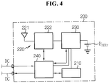
- FIG. 4 is a schematic diagram showing configuration of the master BMU 200 according to an embodiment of the present disclosure.
- the master BMU 200 may include a memory 210, a communication unit 220, a power supply unit 230 and a control unit 240.
- the memory 210 may store an ID table.
- the ID table includes each ID assigned to the plurality of slave BMUs 100-1 ⁇ 100-n.
- the memory 210 is not limited to a particular type and includes any known information storage means capable of recording, deleting, updating and reading data.
- the memory 210 may be DRAM, SDRAM, flash memory, ROM, EEPROM, and register.
- the memory 210 may store program codes defining the processes that can be executed by the control unit 170.
- the memory 210 may be physically separated from the control unit 240, or may be integrated into a chip with the control unit 240.
- the communication unit 220 includes a master antenna 221 and a master communication circuit 222.
- the master antenna 221 and the master communication circuit 222 are operably connected to each other.
- the master communication circuit 222 may demodulate a wireless signal received through the master antenna 221.
- the master communication circuit 222 may modulate a signal to transmit to each slave BMU 100, and wirelessly transmit the modulated signal through the master antenna 221.
- the master antenna 221 may selectively transmit the wireless signal corresponding to the signal modulated by the communication unit 220 to at least one of the plurality of slave BMUs 100-1 ⁇ 100-n.
- the power supply unit 230 generates at least one power source voltage using electrical energy supplied from at least one battery module 20 or auxiliary power B AUX2 .
- the power source voltage generated by the power supply unit 230 may be supplied to the memory 210 and the communication unit 220. Additionally, the power source voltage generated by the power supply unit 230 may be supplied to each processor included in the control unit 240.
- the control unit 240 is operably connected to the memory 210 and the communication unit 220.
- the control unit 240 is configured to manage the overall operation of the master BMU 200. Additionally, the control unit 240 may calculate a State Of Charge (SOC) and/or a State Of Health (SOH) of each of the plurality of battery modules 20-1 ⁇ 20-n based on a wireless signal corresponding to sensing information of each of the plurality of battery modules 20-1 ⁇ 20-n among wireless signals received through the master antenna 221.
- SOC State Of Charge
- SOH State Of Health
- control unit 240 may generate a control signal for controlling the charging, discharging and/or balancing of each of the plurality of slave BMUs 100 based on the calculated SOC and/or SOH, and selectively transmit it to at least one of the plurality of slave BMUs 100-1 ⁇ 100-n through the master antenna 221 and the communication unit 220.
- the control unit 240 includes at least one MCU, and each MCU may selectively include an application-specific integrated circuit (ASIC), a chipset, a logic circuit, a register, a communication modem and a data processing device known in the art to execute various control logics. At least one control logic of the control unit 240 may be combined and the combined control logic may be written in computer-readable code system and recorded in computer-readable recording medium.
- the recording medium is not limited to a particular type when it can be accessed by a processor included in a computer.
- the recording medium includes at least one selected from the group consisting of ROM, RAM, register, CD-ROM, magnetic tape, hard disk, floppy disk and optical data recording device.
- code system may be modulated to a carrier signal and included in a communication carrier at a specified point in time and may be stored and executed in computers connected via a network in distributed manner. Additionally, functional programs, codes and code segments for implementing the combined control logics may be readily inferred by programmers in the technical field to which the present disclosure belongs.
- the battery pack 10 including the battery management system 30 may be installed in a specified object (for example, an electric vehicle). Since then, the battery management system 30 may individually manage the plurality of battery modules 20-1 ⁇ 20-n according to the command from a high-level control unit 1 provided in the specified object.
- the master BMU 200 may transmit the notification signal to the plurality of slave BMUs 100-1 ⁇ 100-n.
- the ignition signal may be for notifying that the battery pack 10 including the battery management system 30 is normally installed in the specified object and can operate according to the command from the high-level control unit 1.
- the notification signal may be for notifying that the use of the battery pack 10 has started to the plurality of slave BMUs 100-1 ⁇ 100-n.
- the high-level control unit 1 receives state information of the plurality of battery modules 100-1 ⁇ 100-n collected by the master BMU 200 from the master BMU 200. Additionally, the high-level control unit 1 outputs, to the master BMU 200, a variety of commands for controlling the battery management system 30 based on the state information of the plurality of battery modules 100-1 ⁇ 100-n received from the master BMU 200.
- the antenna 131 and the wireless communication circuit 132 of the communication unit 130 Before the communication unit 130 of each slave BMU 100 receives the notification signal, the antenna 131 and the wireless communication circuit 132 of the communication unit 130 only perform the function of wirelessly transmitting the results of testing at least one item related to the battery module 20 to the outside. In contrast, after the communication unit 130 of each slave BMU 100 receives the notification signal, the antenna 131 and the wireless communication circuit 132 of the communication unit 130 may perform the function of wirelessly transmitting and receiving the signal related to the battery module 20 to/from the other slave BMU 100 and/or the master BMU 200.
- Each of the plurality of slave BMUs 100-1 ⁇ 100-n may perform communication with the master BMU 200 or the high-level control unit 1 selectively using a wired network and a wireless network.
- slave BMUs 100-1 ⁇ 100-n and the master BMU 200 may communicate with the master BMU 200 via a wired network such as Daisy Chain DC, and when a failure in the master BMU 200 occurs, may transmit information related to the battery module 20 directly to the high-level control unit 1 via a wireless network.
- a wired network such as Daisy Chain DC
- the master BMU 200 may transmit information indicating wired network congestion level and/or wireless network congestion level to the plurality of slave BMUs 100-1 ⁇ 100-n via a wired network and/or a wireless network.
- the wired network congestion level exceeds the threshold
- the plurality of slave BMUs 100-1 ⁇ 100-n may communicate with the master BMU 200 using a wireless network.
- the wireless network congestion level exceeds the threshold
- the plurality of slave BMUs 100-1 ⁇ 100-n may communicate with the master BMU 200 using a wired network.
Landscapes
- Engineering & Computer Science (AREA)
- Chemical & Material Sciences (AREA)
- Chemical Kinetics & Catalysis (AREA)
- Electrochemistry (AREA)
- General Chemical & Material Sciences (AREA)
- Manufacturing & Machinery (AREA)
- Physics & Mathematics (AREA)
- General Physics & Mathematics (AREA)
- Microelectronics & Electronic Packaging (AREA)
- Secondary Cells (AREA)
- Charge And Discharge Circuits For Batteries Or The Like (AREA)
- Tests Of Electric Status Of Batteries (AREA)
Priority Applications (1)
| Application Number | Priority Date | Filing Date | Title |
|---|---|---|---|
| PL18838249T PL3557687T3 (pl) | 2017-07-25 | 2018-06-14 | Jednostka zarządzania akumulatorem i zawierający ją pakiet akumulatorowy |
Applications Claiming Priority (2)
| Application Number | Priority Date | Filing Date | Title |
|---|---|---|---|
| KR1020170094255A KR102173778B1 (ko) | 2017-07-25 | 2017-07-25 | 배터리 관리 유닛 및 이를 포함하는 배터리팩 |
| PCT/KR2018/006721 WO2019022378A1 (fr) | 2017-07-25 | 2018-06-14 | Unité de gestion de batteries et bloc-batterie l'incluant |
Publications (3)
| Publication Number | Publication Date |
|---|---|
| EP3557687A1 true EP3557687A1 (fr) | 2019-10-23 |
| EP3557687A4 EP3557687A4 (fr) | 2020-04-22 |
| EP3557687B1 EP3557687B1 (fr) | 2022-03-09 |
Family
ID=65039731
Family Applications (1)
| Application Number | Title | Priority Date | Filing Date |
|---|---|---|---|
| EP18838249.3A Active EP3557687B1 (fr) | 2017-07-25 | 2018-06-14 | Unité de gestion de batteries et bloc-batterie l'incluant |
Country Status (7)
| Country | Link |
|---|---|
| US (1) | US11070067B2 (fr) |
| EP (1) | EP3557687B1 (fr) |
| JP (1) | JP6996065B2 (fr) |
| KR (1) | KR102173778B1 (fr) |
| CN (1) | CN110192303B (fr) |
| PL (1) | PL3557687T3 (fr) |
| WO (1) | WO2019022378A1 (fr) |
Families Citing this family (21)
| Publication number | Priority date | Publication date | Assignee | Title |
|---|---|---|---|---|
| KR102150147B1 (ko) * | 2017-05-24 | 2020-09-01 | 주식회사 엘지화학 | 배터리 모듈 균등화 장치 및 방법 |
| KR102164547B1 (ko) * | 2017-07-31 | 2020-10-12 | 주식회사 엘지화학 | 배터리 관리 장치 및 이를 포함하는 배터리 팩 |
| KR102202613B1 (ko) * | 2017-09-27 | 2021-01-12 | 주식회사 엘지화학 | 배터리 모듈 균등화 장치, 이를 포함하는 배터리 팩 및 자동차 |
| CN110661305B (zh) * | 2018-06-28 | 2021-01-05 | 宁德时代新能源科技股份有限公司 | 电池组管理系统及其控制方法 |
| KR20200022655A (ko) * | 2018-08-23 | 2020-03-04 | 삼성전자주식회사 | 배터리 관리 장치, 배터리 모듈, 및 배터리 팩 |
| KR20200100967A (ko) * | 2019-02-19 | 2020-08-27 | 주식회사 엘지화학 | Ic 칩 및 이를 이용한 회로 시스템 |
| US11418041B2 (en) * | 2019-03-15 | 2022-08-16 | Lg Energy Solution, Ltd. | Battery system |
| CN111725854B (zh) * | 2019-03-21 | 2021-06-29 | 宁德时代新能源科技股份有限公司 | 储能系统及其控制方法和装置 |
| KR20200128838A (ko) * | 2019-05-07 | 2020-11-17 | 에스케이이노베이션 주식회사 | 다품종 배터리로 구성된 배터리 팩 시스템 |
| KR20210016795A (ko) * | 2019-08-05 | 2021-02-17 | 주식회사 엘지화학 | 에너지 허브 장치 및 에너지 관리 방법 |
| KR20210046108A (ko) * | 2019-10-17 | 2021-04-28 | 삼성전자주식회사 | 배터리 관리 장치 및 시스템 |
| KR20210050991A (ko) * | 2019-10-29 | 2021-05-10 | 주식회사 엘지화학 | 온도 측정 장치 및 이를 포함하는 배터리 장치 |
| KR20210103299A (ko) * | 2020-02-13 | 2021-08-23 | 주식회사 엘지에너지솔루션 | 배터리 제어 시스템, 배터리 팩, 전기 차량 및 상기 배터리 제어 시스템을 위한 제어 방법 |
| KR20210108816A (ko) * | 2020-02-26 | 2021-09-03 | 주식회사 엘지에너지솔루션 | 배터리 정보 제공 장치 및 방법 |
| KR102188634B1 (ko) * | 2020-07-03 | 2020-12-08 | 주식회사 에코전력 | 이모빌리티용 스마트 배터리 모니터링 시스템 |
| KR102541328B1 (ko) * | 2020-12-11 | 2023-06-13 | 주식회사 피엠그로우 | 배터리 정보 관리 방법 및 장치 |
| CN112748298A (zh) * | 2020-12-15 | 2021-05-04 | 深圳市科陆电子科技股份有限公司 | Bms检测系统 |
| WO2022189012A1 (fr) * | 2021-03-08 | 2022-09-15 | Smartiq Innovation Technology Gmbh | Cellule de mesure pour modules de batterie, module de batterie et batterie |
| EP4109120A1 (fr) | 2021-06-23 | 2022-12-28 | C.R.F. Società Consortile per Azioni | Système et procédé de gestion de batterie |
| KR20230020281A (ko) * | 2021-08-03 | 2023-02-10 | 주식회사 엘지에너지솔루션 | 배터리 관리 장치 및 방법 |
| KR102371371B1 (ko) * | 2021-12-17 | 2022-03-07 | 주식회사 유시스 | 도킹 드론 |
Family Cites Families (36)
| Publication number | Priority date | Publication date | Assignee | Title |
|---|---|---|---|---|
| KR100463115B1 (ko) * | 1998-10-31 | 2006-01-27 | 씨제이 주식회사 | 당질전분폐수의 생물학적 처리 방법 및 미생물 |
| KR100613230B1 (ko) * | 2004-01-13 | 2006-08-18 | (주)라임테크 | 제강 조재제용 생석회와 그 제조방법 |
| JP4137842B2 (ja) | 2004-05-19 | 2008-08-20 | パナソニックEvエナジー株式会社 | 二次電池の容量均等化装置 |
| KR100846710B1 (ko) * | 2006-09-07 | 2008-07-16 | 삼성에스디아이 주식회사 | 배터리 관리 시스템 및 그의 구동 방법 |
| KR100908716B1 (ko) * | 2007-03-02 | 2009-07-22 | 삼성에스디아이 주식회사 | 배터리 관리 시스템 및 그의 구동 방법 |
| JP5208714B2 (ja) | 2008-12-22 | 2013-06-12 | 株式会社東芝 | 組電池システム |
| JP2010279120A (ja) | 2009-05-27 | 2010-12-09 | Mitsubishi Motors Corp | 電気自動車の電池監視装置 |
| CN101692502B (zh) * | 2009-09-25 | 2011-08-17 | 深圳市航盛电子股份有限公司 | 电池管理系统 |
| KR101074785B1 (ko) * | 2010-05-31 | 2011-10-19 | 삼성에스디아이 주식회사 | 배터리 관리 시스템 및 이의 제어 방법, 및 배터리 관리 시스템을 포함한 에너지 저장 시스템 |
| JP2011254651A (ja) | 2010-06-03 | 2011-12-15 | Midori Anzen Co Ltd | バッテリ監視システム |
| JP6147668B2 (ja) * | 2010-11-02 | 2017-06-14 | ナビタス ソリューションズ,インコーポレイテッド | スマート電池管理システムのための無線電池エリアネットワーク |
| WO2012066651A1 (fr) * | 2010-11-17 | 2012-05-24 | 株式会社日立製作所 | Système de gestion d'énergie et procédé de gestion d'énergie |
| KR101856663B1 (ko) * | 2011-06-03 | 2018-05-10 | 에스케이이노베이션 주식회사 | 다중팩 병렬 구조의 정보 교환을 위한 2차 전지 관리 시스템 및 방법 |
| JP5844106B2 (ja) | 2011-09-28 | 2016-01-13 | 三洋電機株式会社 | 車両用の電源装置とこの電源装置を備える車両 |
| KR101251812B1 (ko) | 2011-10-05 | 2013-04-09 | 기아자동차주식회사 | 차량용 전원관리시스템 |
| US9065296B2 (en) * | 2012-04-03 | 2015-06-23 | Samsung Sdi Co., Ltd. | Battery pack, method of measuring voltage of the battery pack, and energy storage system including the battery pack |
| KR20140028350A (ko) | 2012-08-28 | 2014-03-10 | 에스케이이노베이션 주식회사 | 셀밸런싱 보조 셀을 이용한 배터리 장치 |
| KR101330410B1 (ko) | 2012-10-31 | 2013-11-15 | 주식회사 현대케피코 | 하이브리드, 전기차 배터리관리장치의 작동 성능 검증 방법 |
| JP5879294B2 (ja) * | 2013-03-29 | 2016-03-08 | 日立オートモティブシステムズ株式会社 | 電池システム |
| US9537328B2 (en) | 2013-05-23 | 2017-01-03 | Samsung Sdi Co., Ltd. | Battery management system and method of driving the same |
| WO2015011801A1 (fr) | 2013-07-24 | 2015-01-29 | 日立オートモティブシステムズ株式会社 | Dispositif de surveillance de système de batterie |
| KR101613230B1 (ko) * | 2013-08-20 | 2016-04-18 | 주식회사 엘지화학 | 통신라인에 고장 발생 시 통신 프로토콜을 변경하는 유선통신유닛 및 이를 포함하는 유선통신시스템 |
| JP2015068784A (ja) | 2013-09-30 | 2015-04-13 | 古河電気工業株式会社 | 組電池の状態診断装置 |
| US20160294019A1 (en) * | 2013-12-16 | 2016-10-06 | Hitachi, Ltd. | Battery system and battery cell management device |
| JP6228666B2 (ja) | 2014-05-26 | 2017-11-08 | 株式会社日立製作所 | 電池システム |
| KR101818515B1 (ko) * | 2014-05-30 | 2018-01-15 | 주식회사 엘지화학 | 배터리팩 생산공정에서의 불량검출장치 및 그 방법 |
| JP6392088B2 (ja) * | 2014-11-13 | 2018-09-19 | 株式会社日立製作所 | 無線電池システム並びにこれに用いるセルコントローラ及びバッテリコントローラ |
| US10498976B2 (en) | 2014-12-05 | 2019-12-03 | Microsoft Technology Licensing, Llc | Virtual focus feedback |
| WO2016132414A1 (fr) | 2015-02-17 | 2016-08-25 | ソニー株式会社 | Module accumulateur d'électricité, dispositif accumulateur d'électricité, système accumulateur d'électricité, procédé de commande, dispositif électronique, véhicule électrique, et système de puissance |
| KR101799564B1 (ko) | 2015-03-12 | 2017-12-20 | 주식회사 엘지화학 | 전력 저장 장치 |
| WO2018069494A1 (fr) * | 2016-10-14 | 2018-04-19 | Universität Zürich | Dosage de l'indoléamine-2,3-dioxygénase servant au diagnostic et au pronostic du cancer de la prostate |
| US10063070B2 (en) * | 2016-11-25 | 2018-08-28 | National Chung Shan Institute Of Science And Technology | Battery active balancing system |
| CN106707216B (zh) * | 2017-01-17 | 2023-03-21 | 广东电网有限责任公司电力科学研究院 | 一种配电自动化终端用电池管理的测试系统 |
| KR102155331B1 (ko) * | 2017-07-06 | 2020-09-11 | 주식회사 엘지화학 | 무선 배터리 관리 시스템 및 이를 포함하는 배터리팩 |
| KR102204301B1 (ko) * | 2017-07-20 | 2021-01-15 | 주식회사 엘지화학 | 무선 배터리 관리 시스템 및 이를 포함하는 배터리팩 |
| KR102173777B1 (ko) | 2017-07-25 | 2020-11-03 | 주식회사 엘지화학 | 마스터 배터리 관리 유닛 및 이를 포함하는 배터리팩 |
-
2017
- 2017-07-25 KR KR1020170094255A patent/KR102173778B1/ko active IP Right Grant
-
2018
- 2018-06-14 WO PCT/KR2018/006721 patent/WO2019022378A1/fr unknown
- 2018-06-14 EP EP18838249.3A patent/EP3557687B1/fr active Active
- 2018-06-14 PL PL18838249T patent/PL3557687T3/pl unknown
- 2018-06-14 CN CN201880006268.2A patent/CN110192303B/zh active Active
- 2018-06-14 JP JP2019531422A patent/JP6996065B2/ja active Active
- 2018-06-14 US US16/476,710 patent/US11070067B2/en active Active
Also Published As
| Publication number | Publication date |
|---|---|
| KR20190011568A (ko) | 2019-02-07 |
| EP3557687B1 (fr) | 2022-03-09 |
| JP6996065B2 (ja) | 2022-01-17 |
| US11070067B2 (en) | 2021-07-20 |
| JP2020504421A (ja) | 2020-02-06 |
| KR102173778B1 (ko) | 2020-11-03 |
| EP3557687A4 (fr) | 2020-04-22 |
| PL3557687T3 (pl) | 2022-06-13 |
| CN110192303A (zh) | 2019-08-30 |
| US20190356143A1 (en) | 2019-11-21 |
| WO2019022378A1 (fr) | 2019-01-31 |
| CN110192303B (zh) | 2022-09-06 |
Similar Documents
| Publication | Publication Date | Title |
|---|---|---|
| EP3557687B1 (fr) | Unité de gestion de batteries et bloc-batterie l'incluant | |
| EP3561940B1 (fr) | Unité principale de gestion d'accumulateurs et bloc-batterie comprenant celle-ci | |
| US10571523B2 (en) | Wireless battery management system and battery pack including same | |
| US11349159B2 (en) | Battery management system and battery pack including same | |
| US20200036194A1 (en) | Wireless battery management apparatus and battery pack including same | |
| US11356824B2 (en) | Wireless control system, wireless control method, and battery pack | |
| US9088052B2 (en) | Battery multi-series system and communication method thereof | |
| CN109565180B (zh) | 用于电池管理的系统和方法 | |
| US11789084B2 (en) | Wireless battery control system, method and battery pack for assigning ID to a plurality of slave management modules | |
| US11428742B2 (en) | Wireless control system, wireless connection method, and battery pack | |
| US20220352563A1 (en) | Wireless battery management system, wireless battery management method and electric vehicle | |
| JP7127248B2 (ja) | バッテリー管理システム、バッテリー管理方法、バッテリーパック及び電気車両 | |
| KR20190051341A (ko) | 체결 인식 기능을 갖춘 배터리 팩 | |
| EP3996237A1 (fr) | Système de commande de batterie, bloc-batterie, véhicule électrique et procédé de définition d'id pour système de commande de batterie | |
| EP3974850A1 (fr) | Dispositif et procédé de diagnostic de relais de batterie parallèle | |
| EP3840102B1 (fr) | Système et procédé de reconnaissance de bms |
Legal Events
| Date | Code | Title | Description |
|---|---|---|---|
| STAA | Information on the status of an ep patent application or granted ep patent |
Free format text: STATUS: THE INTERNATIONAL PUBLICATION HAS BEEN MADE |
|
| PUAI | Public reference made under article 153(3) epc to a published international application that has entered the european phase |
Free format text: ORIGINAL CODE: 0009012 |
|
| STAA | Information on the status of an ep patent application or granted ep patent |
Free format text: STATUS: REQUEST FOR EXAMINATION WAS MADE |
|
| 17P | Request for examination filed |
Effective date: 20190717 |
|
| AK | Designated contracting states |
Kind code of ref document: A1 Designated state(s): AL AT BE BG CH CY CZ DE DK EE ES FI FR GB GR HR HU IE IS IT LI LT LU LV MC MK MT NL NO PL PT RO RS SE SI SK SM TR |
|
| AX | Request for extension of the european patent |
Extension state: BA ME |
|
| A4 | Supplementary search report drawn up and despatched |
Effective date: 20200320 |
|
| RIC1 | Information provided on ipc code assigned before grant |
Ipc: H01M 10/48 20060101ALI20200316BHEP Ipc: G01R 31/36 20200101ALI20200316BHEP Ipc: H01M 10/42 20060101AFI20200316BHEP |
|
| DAV | Request for validation of the european patent (deleted) | ||
| DAX | Request for extension of the european patent (deleted) | ||
| GRAP | Despatch of communication of intention to grant a patent |
Free format text: ORIGINAL CODE: EPIDOSNIGR1 |
|
| STAA | Information on the status of an ep patent application or granted ep patent |
Free format text: STATUS: GRANT OF PATENT IS INTENDED |
|
| INTG | Intention to grant announced |
Effective date: 20211124 |
|
| RAP1 | Party data changed (applicant data changed or rights of an application transferred) |
Owner name: LG ENERGY SOLUTION LTD. |
|
| GRAS | Grant fee paid |
Free format text: ORIGINAL CODE: EPIDOSNIGR3 |
|
| GRAA | (expected) grant |
Free format text: ORIGINAL CODE: 0009210 |
|
| STAA | Information on the status of an ep patent application or granted ep patent |
Free format text: STATUS: THE PATENT HAS BEEN GRANTED |
|
| AK | Designated contracting states |
Kind code of ref document: B1 Designated state(s): AL AT BE BG CH CY CZ DE DK EE ES FI FR GB GR HR HU IE IS IT LI LT LU LV MC MK MT NL NO PL PT RO RS SE SI SK SM TR |
|
| REG | Reference to a national code |
Ref country code: CH Ref legal event code: EP Ref country code: AT Ref legal event code: REF Ref document number: 1474894 Country of ref document: AT Kind code of ref document: T Effective date: 20220315 |
|
| RAP4 | Party data changed (patent owner data changed or rights of a patent transferred) |
Owner name: LG ENERGY SOLUTION, LTD. |
|
| REG | Reference to a national code |
Ref country code: IE Ref legal event code: FG4D |
|
| REG | Reference to a national code |
Ref country code: DE Ref legal event code: R096 Ref document number: 602018032119 Country of ref document: DE |
|
| REG | Reference to a national code |
Ref country code: SE Ref legal event code: TRGR |
|
| REG | Reference to a national code |
Ref country code: LT Ref legal event code: MG9D |
|
| REG | Reference to a national code |
Ref country code: NL Ref legal event code: MP Effective date: 20220309 |
|
| PG25 | Lapsed in a contracting state [announced via postgrant information from national office to epo] |
Ref country code: RS Free format text: LAPSE BECAUSE OF FAILURE TO SUBMIT A TRANSLATION OF THE DESCRIPTION OR TO PAY THE FEE WITHIN THE PRESCRIBED TIME-LIMIT Effective date: 20220309 Ref country code: NO Free format text: LAPSE BECAUSE OF FAILURE TO SUBMIT A TRANSLATION OF THE DESCRIPTION OR TO PAY THE FEE WITHIN THE PRESCRIBED TIME-LIMIT Effective date: 20220609 Ref country code: LT Free format text: LAPSE BECAUSE OF FAILURE TO SUBMIT A TRANSLATION OF THE DESCRIPTION OR TO PAY THE FEE WITHIN THE PRESCRIBED TIME-LIMIT Effective date: 20220309 Ref country code: HR Free format text: LAPSE BECAUSE OF FAILURE TO SUBMIT A TRANSLATION OF THE DESCRIPTION OR TO PAY THE FEE WITHIN THE PRESCRIBED TIME-LIMIT Effective date: 20220309 Ref country code: BG Free format text: LAPSE BECAUSE OF FAILURE TO SUBMIT A TRANSLATION OF THE DESCRIPTION OR TO PAY THE FEE WITHIN THE PRESCRIBED TIME-LIMIT Effective date: 20220609 |
|
| REG | Reference to a national code |
Ref country code: AT Ref legal event code: MK05 Ref document number: 1474894 Country of ref document: AT Kind code of ref document: T Effective date: 20220309 |
|
| PG25 | Lapsed in a contracting state [announced via postgrant information from national office to epo] |
Ref country code: LV Free format text: LAPSE BECAUSE OF FAILURE TO SUBMIT A TRANSLATION OF THE DESCRIPTION OR TO PAY THE FEE WITHIN THE PRESCRIBED TIME-LIMIT Effective date: 20220309 Ref country code: GR Free format text: LAPSE BECAUSE OF FAILURE TO SUBMIT A TRANSLATION OF THE DESCRIPTION OR TO PAY THE FEE WITHIN THE PRESCRIBED TIME-LIMIT Effective date: 20220610 Ref country code: FI Free format text: LAPSE BECAUSE OF FAILURE TO SUBMIT A TRANSLATION OF THE DESCRIPTION OR TO PAY THE FEE WITHIN THE PRESCRIBED TIME-LIMIT Effective date: 20220309 |
|
| PG25 | Lapsed in a contracting state [announced via postgrant information from national office to epo] |
Ref country code: NL Free format text: LAPSE BECAUSE OF FAILURE TO SUBMIT A TRANSLATION OF THE DESCRIPTION OR TO PAY THE FEE WITHIN THE PRESCRIBED TIME-LIMIT Effective date: 20220309 |
|
| PG25 | Lapsed in a contracting state [announced via postgrant information from national office to epo] |
Ref country code: SM Free format text: LAPSE BECAUSE OF FAILURE TO SUBMIT A TRANSLATION OF THE DESCRIPTION OR TO PAY THE FEE WITHIN THE PRESCRIBED TIME-LIMIT Effective date: 20220309 Ref country code: SK Free format text: LAPSE BECAUSE OF FAILURE TO SUBMIT A TRANSLATION OF THE DESCRIPTION OR TO PAY THE FEE WITHIN THE PRESCRIBED TIME-LIMIT Effective date: 20220309 Ref country code: RO Free format text: LAPSE BECAUSE OF FAILURE TO SUBMIT A TRANSLATION OF THE DESCRIPTION OR TO PAY THE FEE WITHIN THE PRESCRIBED TIME-LIMIT Effective date: 20220309 Ref country code: PT Free format text: LAPSE BECAUSE OF FAILURE TO SUBMIT A TRANSLATION OF THE DESCRIPTION OR TO PAY THE FEE WITHIN THE PRESCRIBED TIME-LIMIT Effective date: 20220711 Ref country code: ES Free format text: LAPSE BECAUSE OF FAILURE TO SUBMIT A TRANSLATION OF THE DESCRIPTION OR TO PAY THE FEE WITHIN THE PRESCRIBED TIME-LIMIT Effective date: 20220309 Ref country code: EE Free format text: LAPSE BECAUSE OF FAILURE TO SUBMIT A TRANSLATION OF THE DESCRIPTION OR TO PAY THE FEE WITHIN THE PRESCRIBED TIME-LIMIT Effective date: 20220309 Ref country code: CZ Free format text: LAPSE BECAUSE OF FAILURE TO SUBMIT A TRANSLATION OF THE DESCRIPTION OR TO PAY THE FEE WITHIN THE PRESCRIBED TIME-LIMIT Effective date: 20220309 Ref country code: AT Free format text: LAPSE BECAUSE OF FAILURE TO SUBMIT A TRANSLATION OF THE DESCRIPTION OR TO PAY THE FEE WITHIN THE PRESCRIBED TIME-LIMIT Effective date: 20220309 |
|
| PG25 | Lapsed in a contracting state [announced via postgrant information from national office to epo] |
Ref country code: IS Free format text: LAPSE BECAUSE OF FAILURE TO SUBMIT A TRANSLATION OF THE DESCRIPTION OR TO PAY THE FEE WITHIN THE PRESCRIBED TIME-LIMIT Effective date: 20220709 Ref country code: AL Free format text: LAPSE BECAUSE OF FAILURE TO SUBMIT A TRANSLATION OF THE DESCRIPTION OR TO PAY THE FEE WITHIN THE PRESCRIBED TIME-LIMIT Effective date: 20220309 |
|
| REG | Reference to a national code |
Ref country code: DE Ref legal event code: R097 Ref document number: 602018032119 Country of ref document: DE |
|
| PLBE | No opposition filed within time limit |
Free format text: ORIGINAL CODE: 0009261 |
|
| STAA | Information on the status of an ep patent application or granted ep patent |
Free format text: STATUS: NO OPPOSITION FILED WITHIN TIME LIMIT |
|
| PG25 | Lapsed in a contracting state [announced via postgrant information from national office to epo] |
Ref country code: MC Free format text: LAPSE BECAUSE OF FAILURE TO SUBMIT A TRANSLATION OF THE DESCRIPTION OR TO PAY THE FEE WITHIN THE PRESCRIBED TIME-LIMIT Effective date: 20220309 Ref country code: DK Free format text: LAPSE BECAUSE OF FAILURE TO SUBMIT A TRANSLATION OF THE DESCRIPTION OR TO PAY THE FEE WITHIN THE PRESCRIBED TIME-LIMIT Effective date: 20220309 |
|
| REG | Reference to a national code |
Ref country code: CH Ref legal event code: PL |
|
| 26N | No opposition filed |
Effective date: 20221212 |
|
| REG | Reference to a national code |
Ref country code: BE Ref legal event code: MM Effective date: 20220630 |
|
| PG25 | Lapsed in a contracting state [announced via postgrant information from national office to epo] |
Ref country code: SI Free format text: LAPSE BECAUSE OF FAILURE TO SUBMIT A TRANSLATION OF THE DESCRIPTION OR TO PAY THE FEE WITHIN THE PRESCRIBED TIME-LIMIT Effective date: 20220309 |
|
| PG25 | Lapsed in a contracting state [announced via postgrant information from national office to epo] |
Ref country code: LU Free format text: LAPSE BECAUSE OF NON-PAYMENT OF DUE FEES Effective date: 20220614 Ref country code: LI Free format text: LAPSE BECAUSE OF NON-PAYMENT OF DUE FEES Effective date: 20220630 Ref country code: IE Free format text: LAPSE BECAUSE OF NON-PAYMENT OF DUE FEES Effective date: 20220614 Ref country code: CH Free format text: LAPSE BECAUSE OF NON-PAYMENT OF DUE FEES Effective date: 20220630 |
|
| PG25 | Lapsed in a contracting state [announced via postgrant information from national office to epo] |
Ref country code: BE Free format text: LAPSE BECAUSE OF NON-PAYMENT OF DUE FEES Effective date: 20220630 |
|
| P01 | Opt-out of the competence of the unified patent court (upc) registered |
Effective date: 20230412 |
|
| PG25 | Lapsed in a contracting state [announced via postgrant information from national office to epo] |
Ref country code: IT Free format text: LAPSE BECAUSE OF FAILURE TO SUBMIT A TRANSLATION OF THE DESCRIPTION OR TO PAY THE FEE WITHIN THE PRESCRIBED TIME-LIMIT Effective date: 20220309 |
|
| PGFP | Annual fee paid to national office [announced via postgrant information from national office to epo] |
Ref country code: FR Payment date: 20230522 Year of fee payment: 6 Ref country code: DE Payment date: 20230522 Year of fee payment: 6 |
|
| PGFP | Annual fee paid to national office [announced via postgrant information from national office to epo] |
Ref country code: SE Payment date: 20230523 Year of fee payment: 6 Ref country code: PL Payment date: 20230523 Year of fee payment: 6 |
|
| PGFP | Annual fee paid to national office [announced via postgrant information from national office to epo] |
Ref country code: GB Payment date: 20230523 Year of fee payment: 6 |
|
| PG25 | Lapsed in a contracting state [announced via postgrant information from national office to epo] |
Ref country code: HU Free format text: LAPSE BECAUSE OF FAILURE TO SUBMIT A TRANSLATION OF THE DESCRIPTION OR TO PAY THE FEE WITHIN THE PRESCRIBED TIME-LIMIT; INVALID AB INITIO Effective date: 20180614 |
|
| PG25 | Lapsed in a contracting state [announced via postgrant information from national office to epo] |
Ref country code: MK Free format text: LAPSE BECAUSE OF FAILURE TO SUBMIT A TRANSLATION OF THE DESCRIPTION OR TO PAY THE FEE WITHIN THE PRESCRIBED TIME-LIMIT Effective date: 20220309 Ref country code: CY Free format text: LAPSE BECAUSE OF FAILURE TO SUBMIT A TRANSLATION OF THE DESCRIPTION OR TO PAY THE FEE WITHIN THE PRESCRIBED TIME-LIMIT Effective date: 20220309 |