EP3557067A1 - Kolbenrotor, kurbelwelle, rotationsverdichter und verfahren zur montage der kurbelwelle - Google Patents
Kolbenrotor, kurbelwelle, rotationsverdichter und verfahren zur montage der kurbelwelle Download PDFInfo
- Publication number
- EP3557067A1 EP3557067A1 EP19169260.7A EP19169260A EP3557067A1 EP 3557067 A1 EP3557067 A1 EP 3557067A1 EP 19169260 A EP19169260 A EP 19169260A EP 3557067 A1 EP3557067 A1 EP 3557067A1
- Authority
- EP
- European Patent Office
- Prior art keywords
- shaft portion
- axis
- rotor
- eccentric shaft
- eccentric
- Prior art date
- Legal status (The legal status is an assumption and is not a legal conclusion. Google has not performed a legal analysis and makes no representation as to the accuracy of the status listed.)
- Granted
Links
Images


Classifications
-
- F—MECHANICAL ENGINEERING; LIGHTING; HEATING; WEAPONS; BLASTING
- F04—POSITIVE - DISPLACEMENT MACHINES FOR LIQUIDS; PUMPS FOR LIQUIDS OR ELASTIC FLUIDS
- F04C—ROTARY-PISTON, OR OSCILLATING-PISTON, POSITIVE-DISPLACEMENT MACHINES FOR LIQUIDS; ROTARY-PISTON, OR OSCILLATING-PISTON, POSITIVE-DISPLACEMENT PUMPS
- F04C29/00—Component parts, details or accessories of pumps or pumping installations, not provided for in groups F04C18/00 - F04C28/00
- F04C29/0042—Driving elements, brakes, couplings, transmissions specially adapted for pumps
- F04C29/005—Means for transmitting movement from the prime mover to driven parts of the pump, e.g. clutches, couplings, transmissions
- F04C29/0057—Means for transmitting movement from the prime mover to driven parts of the pump, e.g. clutches, couplings, transmissions for eccentric movement
-
- F—MECHANICAL ENGINEERING; LIGHTING; HEATING; WEAPONS; BLASTING
- F04—POSITIVE - DISPLACEMENT MACHINES FOR LIQUIDS; PUMPS FOR LIQUIDS OR ELASTIC FLUIDS
- F04C—ROTARY-PISTON, OR OSCILLATING-PISTON, POSITIVE-DISPLACEMENT MACHINES FOR LIQUIDS; ROTARY-PISTON, OR OSCILLATING-PISTON, POSITIVE-DISPLACEMENT PUMPS
- F04C18/00—Rotary-piston pumps specially adapted for elastic fluids
- F04C18/30—Rotary-piston pumps specially adapted for elastic fluids having the characteristics covered by two or more of groups F04C18/02, F04C18/08, F04C18/22, F04C18/24, F04C18/48, or having the characteristics covered by one of these groups together with some other type of movement between co-operating members
- F04C18/34—Rotary-piston pumps specially adapted for elastic fluids having the characteristics covered by two or more of groups F04C18/02, F04C18/08, F04C18/22, F04C18/24, F04C18/48, or having the characteristics covered by one of these groups together with some other type of movement between co-operating members having the movement defined in group F04C18/08 or F04C18/22 and relative reciprocation between the co-operating members
-
- F—MECHANICAL ENGINEERING; LIGHTING; HEATING; WEAPONS; BLASTING
- F04—POSITIVE - DISPLACEMENT MACHINES FOR LIQUIDS; PUMPS FOR LIQUIDS OR ELASTIC FLUIDS
- F04C—ROTARY-PISTON, OR OSCILLATING-PISTON, POSITIVE-DISPLACEMENT MACHINES FOR LIQUIDS; ROTARY-PISTON, OR OSCILLATING-PISTON, POSITIVE-DISPLACEMENT PUMPS
- F04C23/00—Combinations of two or more pumps, each being of rotary-piston or oscillating-piston type, specially adapted for elastic fluids; Pumping installations specially adapted for elastic fluids; Multi-stage pumps specially adapted for elastic fluids
- F04C23/001—Combinations of two or more pumps, each being of rotary-piston or oscillating-piston type, specially adapted for elastic fluids; Pumping installations specially adapted for elastic fluids; Multi-stage pumps specially adapted for elastic fluids of similar working principle
-
- F—MECHANICAL ENGINEERING; LIGHTING; HEATING; WEAPONS; BLASTING
- F04—POSITIVE - DISPLACEMENT MACHINES FOR LIQUIDS; PUMPS FOR LIQUIDS OR ELASTIC FLUIDS
- F04C—ROTARY-PISTON, OR OSCILLATING-PISTON, POSITIVE-DISPLACEMENT MACHINES FOR LIQUIDS; ROTARY-PISTON, OR OSCILLATING-PISTON, POSITIVE-DISPLACEMENT PUMPS
- F04C2230/00—Manufacture
- F04C2230/60—Assembly methods
-
- F—MECHANICAL ENGINEERING; LIGHTING; HEATING; WEAPONS; BLASTING
- F04—POSITIVE - DISPLACEMENT MACHINES FOR LIQUIDS; PUMPS FOR LIQUIDS OR ELASTIC FLUIDS
- F04C—ROTARY-PISTON, OR OSCILLATING-PISTON, POSITIVE-DISPLACEMENT MACHINES FOR LIQUIDS; ROTARY-PISTON, OR OSCILLATING-PISTON, POSITIVE-DISPLACEMENT PUMPS
- F04C2240/00—Components
- F04C2240/20—Rotors
-
- F—MECHANICAL ENGINEERING; LIGHTING; HEATING; WEAPONS; BLASTING
- F04—POSITIVE - DISPLACEMENT MACHINES FOR LIQUIDS; PUMPS FOR LIQUIDS OR ELASTIC FLUIDS
- F04C—ROTARY-PISTON, OR OSCILLATING-PISTON, POSITIVE-DISPLACEMENT MACHINES FOR LIQUIDS; ROTARY-PISTON, OR OSCILLATING-PISTON, POSITIVE-DISPLACEMENT PUMPS
- F04C2240/00—Components
- F04C2240/60—Shafts
-
- F—MECHANICAL ENGINEERING; LIGHTING; HEATING; WEAPONS; BLASTING
- F04—POSITIVE - DISPLACEMENT MACHINES FOR LIQUIDS; PUMPS FOR LIQUIDS OR ELASTIC FLUIDS
- F04C—ROTARY-PISTON, OR OSCILLATING-PISTON, POSITIVE-DISPLACEMENT MACHINES FOR LIQUIDS; ROTARY-PISTON, OR OSCILLATING-PISTON, POSITIVE-DISPLACEMENT PUMPS
- F04C2240/00—Components
- F04C2240/70—Use of multiplicity of similar components; Modular construction
-
- F—MECHANICAL ENGINEERING; LIGHTING; HEATING; WEAPONS; BLASTING
- F04—POSITIVE - DISPLACEMENT MACHINES FOR LIQUIDS; PUMPS FOR LIQUIDS OR ELASTIC FLUIDS
- F04C—ROTARY-PISTON, OR OSCILLATING-PISTON, POSITIVE-DISPLACEMENT MACHINES FOR LIQUIDS; ROTARY-PISTON, OR OSCILLATING-PISTON, POSITIVE-DISPLACEMENT PUMPS
- F04C23/00—Combinations of two or more pumps, each being of rotary-piston or oscillating-piston type, specially adapted for elastic fluids; Pumping installations specially adapted for elastic fluids; Multi-stage pumps specially adapted for elastic fluids
- F04C23/008—Hermetic pumps
Definitions
- the present invention relates to a piston rotor, a crankshaft, a rotary compressor, and an assembling method of the crankshaft.
- an apparatus used for compression of a refrigerant in an air conditioner an apparatus including an accumulator and a compressor is known.
- the accumulator separates the refrigerant into gas and liquid prior to introduction into the compressor.
- the compressor and the accumulator are connected by a suction pipe.
- the compressor compresses only the gas phase refrigerant supplied from the accumulator through the suction pipe and generates a high pressure gas phase refrigerant.
- PTL 1 describes a compressor including a shaft (a crankshaft), a roller (a rotor) installed at an eccentric portion of the shaft, a cylinder having a cylinder chamber which accommodates the roller, and a front head and a rear head which serve as bearings at an end surface of the cylinder.
- the crankshaft may be bent due to a gas load when the refrigerant is compressed, and the crankshaft may be inclined with respect to the rotor.
- the rotor may come into partial contact with the crankshaft.
- stress generated in the crankshaft may be partially increased, thus a friction loss may increase, and the performance of the compressor may deteriorate, or reliability may be lowered. Therefore, the demand for a compressor which can limit influences from deflection of the crankshaft is increasing.
- the present invention has been realized to solve the above-described problems, and an object thereof is to provide a piston rotor, a crankshaft, a rotary compressor, and an assembling method of the crankshaft capable of minimizing deterioration in performance of the compressor due to deflection.
- a piston rotor of a crankshaft which is configured to rotate around an axis in a rotary compressor, including a plurality of rotor separate bodies respectively formed in an annular shape, wherein the plurality of rotor separate bodies are movable relative to each other in a state in which they are in contact with each other.
- the plurality of rotor separate bodies may have the same lengths in a thickness direction.
- a crankshaft including a first shaft portion which extends along an axis, a first eccentric shaft portion which is provided on one side of the first shaft portion in a direction of the axis in which the axis extends, is eccentric in a radial direction with respect to the axis and has a radial length greater than that of the first shaft portion, a second shaft portion which extends along the axis and is installed on one side of the first eccentric shaft in the direction of the axis, and the piston rotor according to the above-described aspect, wherein the piston rotor is disposed to cover the first eccentric shaft portion from outside in the radial direction.
- the crankshaft may further include a second eccentric shaft portion which is provided on one side of the second shaft portion in the direction of the axis, is eccentric in a direction different from that of the first eccentric shaft portion and has a radial length larger than that of the second shaft portion and smaller than that of the first eccentric shaft portion, an annular second piston rotor which covers the second eccentric shaft portion from an outside in the radial direction, and a third shaft portion which extends along the axis and is installed on one side of the second eccentric shaft portion in the direction of the axis, and each of the second shaft portion and the third shaft portion may have a radial length smaller than that of the first eccentric shaft portion, the first eccentric shaft portion is disposed to be partially recessed inward with respect to the first shaft portion in the radial direction, and a length of each of the rotor separate bodies in the direction of the axis may be equal to or less than a length of the second shaft portion in the direction of the axis.
- an axial center of the first eccentric shaft portion and an axial center of the respective rotor separate bodies are made to coincide with each other by moving the rotor separate bodies from the third shaft portion side in the direction of the axis to a position of the second shaft portion and moving them in the radial direction. That is, the plurality of rotor separate bodies can be smoothly fitted to the first eccentric shaft portion. Therefore, the length of the second shaft portion in the direction of the axis can be reduced regardless of the length of the first piston rotor as a whole in the direction of the axis. In the crankshaft, the second shaft portion is most likely to be bent with respect to the first shaft portion and the third shaft portion. Deflection can be effectively minimized by reducing the length of the second shaft portion. Furthermore, the overall length of the shaft main body in the direction of the axis can be reduced by shortening the second shaft portion. Accordingly, the rigidity of the shaft main body can be increased, and the likelihood of deflection can be reduced.
- a rotary compressor including the crankshaft according to the above-described aspect, a compression mechanism portion which accommodates the first eccentric shaft portion and has a compression chamber that is configured to compress a fluid in accordance with rotation of the crankshaft, and a bearing portion which is configured to rotatably support the first shaft portion.
- an assembling method of a crankshaft which includes a first shaft portion which extends along an axis, a first eccentric shaft portion which is provided on one side of the first shaft portion in a direction of the axis in which the axis extends, is eccentric in a radial direction with respect to the axis and has a radial length greater than that of the first shaft portion, a second shaft portion which extends along the axis and is installed on one side of the first eccentric shaft in the direction of the axis, a first piston rotor having a plurality of rotor separate bodies respectively formed in an annular shape to cover the first eccentric shaft portion from an outside in the radial direction with respect to the axis, a second eccentric shaft portion which is provided on one side of the second shaft portion in the direction of the axis, is eccentric in a direction different from the first eccentric shaft portion and has a radial length larger than that of the second shaft portion, an annular second piston rotor which
- a compressor system 100 includes an accumulator 24, suction pipes 26A and 26B (a first suction pipe 26A and a second suction pipe 26B), and a compressor 10.
- the compressor 10 according to the embodiment is a two-cylinder type rotary compressor.
- the compressor 10 includes a motor 18 driven by an external power supply, and a compression mechanism portion 10A which is driven by the motor 18 and compresses a refrigerant (fluid), and a housing 11 which covers the motor 18 and the compression mechanism portion 10A.
- the compression mechanism portion 10A includes a crankshaft 16 rotated by the motor 18, piston rotors 13A and 13B (a first piston rotor 13A and a second piston rotor 13B) which eccentrically rotate in accordance with rotation of the crankshaft 16, and cylinders 12A and 12B (a first cylinder 12A and a second cylinder 12B) in which compression chambers for accommodating the piston rotors 13A and 13B are formed therein.
- the disk-shaped first cylinder 12A and second cylinder 12B are provided in two upper and lower stages in the cylindrical housing 11.
- the housing 11 forms a discharge space V, in which the compressed refrigerant is discharged, by surrounding the first cylinder 12A and the second cylinder 12B.
- the cylindrical first piston rotors 13A and second piston rotors 13B each having an external form smaller than an inside between inner wall surfaces of each of the first cylinder 12A and the second cylinder 12B are disposed inside the first cylinder 12A and the second cylinder 12B.
- the first piston rotor 13A and the second piston rotor 13B are respectively inserted and fixed into eccentric shaft portions 14A and 14B (a first eccentric shaft portion 14A and a second eccentric shaft portion 14B) in the crankshaft 16.
- Phases of the first piston rotor 13A of the upper cylinder 12A and the second piston rotor 13B of the lower cylinder 12B are provided to be different from each other by 180 °. That is, the first piston rotor 13A is eccentric so that a position thereof in a peripheral direction around an axis O is opposite to that of the second piston rotor 13B. Further, a disk-shaped partition plate 15 is provided between the upper and lower first cylinder 12A and second cylinder 12B. A space R in the upper first cylinder 12A and a space R in the lower second cylinder 12B are partitioned from each other by the partition plate 15, and thus an upper compression chamber R1 and a lower compression chamber R2 are formed.
- the first cylinder 12A and the second cylinder 12B are fixed to the housing 11 by an upper bearing portion 17A and a lower bearing portion 17B. More specifically, the upper bearing portion 17A is fixed to an upper portion of the first cylinder 12A and formed in a disk shape. An outer peripheral surface of the upper bearing portion 17A is fixed to an inner peripheral surface of the housing 11. The lower bearing portion 17B is fixed to a lower portion of the second cylinder 12B and formed in a disk shape. An outer peripheral surface of the lower bearing portion 17B is fixed to the inner peripheral surface of the housing 11. That is, the first cylinder 12A and the second cylinder 12B are not directly fixed to the housing 11 but are fixed to the housing 11 via the upper bearing portion 17A and the lower bearing portion 17B.
- the accumulator 24 for gas-liquid separation of the refrigerant prior to supply to the compressor 10 is fixed to the housing 11 via a stay 25.
- a refrigerant before compression is stored in the accumulator 24.
- the first suction pipe 26A and the second suction pipe 26B for suctioning the refrigerant in the accumulator 24 to the compressor 10 are provided between the accumulator 24 and the compressor 10. First ends (one ends) of the first suction pipe 26A and the second suction pipe 26B are connected to a lower portion of the accumulator 24.
- Second ends (the other ends) of the first suction pipe 26A and the second suction pipe 26B are respectively connected to suction ports 23A and 23B (a first suction port 23A and a second suction port 23B) formed in the first cylinder 12A and the second cylinder 12B through openings 22A and 22B.
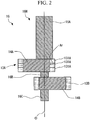
- the crankshaft 16 extends along the axis O.
- the crankshaft 16 is rotatably supported around the axis O by the upper bearing portion 17A and the lower bearing portion 17B.
- the crankshaft 16 includes a shaft main body 16H, a first piston rotor 13A, and a second piston rotor 13B.
- the shaft main body 16H includes a first shaft portion (a main shaft) 16A, a first eccentric shaft portion (an upper crank pin) 14A, and a second shaft portion (an intermediate shaft) 16B, a second eccentric shaft (a lower crank pin) 14B, and a third shaft (a subshaft) 16C.
- the first shaft portion 16A extends along the axis O.
- the first shaft portion 16A is formed to have the longest length in a direction of the axis O in the shaft main body 16H.
- the first eccentric shaft portion 14A is integrally provided on one side of (a side below) the first shaft portion 16A in the direction of the axis O.
- the first eccentric shaft portion 14A is eccentric in a radial direction with respect to the axis O and is formed in a disk shape having a radial length greater than that of the first shaft portion 16A. Therefore, a portion of an outer peripheral surface of the first eccentric shaft portion 14A which coincides with an eccentric direction protrudes outward from an outer peripheral surface of the first shaft portion 16A in the radial direction.
- a portion (a retracted portion Ar) of the outer peripheral surface of the first eccentric shaft portion 14A which is opposite to the eccentric direction is located inward from the outer peripheral surface of the first shaft portion 16A in radial direction with respect to the direction of the axis O. That is, the first eccentric shaft portion 14A is formed to be recessed from the outer peripheral surface of the first shaft portion 16A in the retracted portion Ar.
- the first eccentric shaft portion 14A is accommodated in the above-described compression chamber R1.
- the first piston rotor 13A is installed in the first eccentric shaft portion 14A. The detailed constitution of the first piston rotor 13A will be described later.
- the second shaft portion 16B extends along the axis O and is integrally provided on one side of the first eccentric shaft portion 14A in the direction of the axis O.
- the second shaft portion 16B has a smaller radial length than that of the first shaft portion 16A.
- the second shaft portion 16B is disposed coaxially with the first shaft portion 16A.
- a length of the second shaft portion 16B in the direction of the axis O is smaller than any of the first shaft portion 16A, the first eccentric shaft portion 14A, the second eccentric shaft portion 14B, and the third shaft portion 16C.
- the second eccentric shaft portion 14B is integrally provided on one side of the second shaft portion 16B in the direction of the axis O.
- the second eccentric shaft portion 14B is formed in a disk shape having a larger diameter than that of the second shaft portion 16B.
- the second eccentric shaft portion 14B protrudes outward in the radial direction from the outer peripheral surfaces of the second shaft portion 16B and the third shaft portion 16C over the entire periphery thereof.
- An annular second piston rotor 13B is installed on the outer peripheral surface of the second eccentric shaft portion 14B to cover the second eccentric shaft portion 14B from the outside in the radial direction.
- a radial length of the second eccentric shaft portion 14B is the same as a radial length of the first eccentric shaft portion 14A.
- An outer radial length of the second eccentric shaft portion 14B needs to be larger than a radial length of the first eccentric shaft portion 14A.
- the third shaft portion 16C extends along the axis O and is integrally installed on one side of the second eccentric shaft portion 14B in the direction of the axis O.
- the third shaft portion 16C has a radial length smaller than that of the first shaft portion 16A and the same as that of the second shaft portion 16B.
- the third shaft portion 16C is disposed coaxially with the first shaft portion 16A.
- the first shaft portion 16A protrudes upward (in a direction in which the motor 18 is located) from the upper bearing portion 17A.
- a rotor 19A of a motor 18 for rotationally driving the crankshaft 16 is integrally provided at a portion of the first shaft portion 16A which protrudes upward from the upper bearing portion 17A.
- a stator 19B is fixed to the inner peripheral surface of the housing 11 to face an outer peripheral portion of the rotor 19A.
- the first piston rotor 13A is a piston rotor having a plurality of (three in the embodiment) rotor separate bodies 131A which are in contact with each other in the direction of the axis O.
- the respective rotor separate bodies 131A in an annular shape are in contact with each other in the direction of the axis O.
- lengths (lengths of the thickness direction) of the respective rotor separate bodies 131A in the direction of the axis O are the same as each other and have the same shape. That is, the first piston rotor 13A is equally divided (equally divided into three portions) in the direction of the axis O.
- a length of the first eccentric shaft portion 14A in the direction of the axis O is the same as a length of the three rotor separate bodies 131A. Furthermore, a length of one rotor separate body 131A in the direction of the axis O is less than or equal to a length of the second shaft portion 16B in the direction of the axis O. More specifically, the lengths of the respective rotor separate bodies 131A in the direction of the axis O are preferably slightly smaller than the length of the second shaft portion 16B in the direction of the axis O.
- the retracted portion Ar of the first eccentric shaft portion 14A is located inward from the outer peripheral surface of the first shaft portion 16A in the radial direction with respect to the direction of the axis O.
- the rotor separate body 131A located furthest toward the other side (that is, the uppermost side) in the direction of the axis O is in contact with an end surface A1 of the first shaft portion 16A.
- the second piston rotor 13B is formed as one member without being divided in the direction of the axis O.
- a length of the second piston rotor 13B in the direction of the axis O is equal to a length of the second eccentric shaft portion 14B in the direction of the axis O.
- the assembling method of the crankshaft 16 includes a preparation process S1, a first rotor installation process S2, and a second rotor installation process S3.
- the above-described shaft main body 16H is prepared.
- a method of sequentially welding the first shaft portion 16A, the first eccentric shaft portion 14A, the second shaft portion 16B, the second eccentric shaft portion 14B, and the third shaft portion 16C in the direction of the axis O or a method of integrally cutting and forming them may be used.
- the above-described first piston rotor 13A is installed on the first eccentric shaft portion 14A in the shaft main body 16H.
- the rotor separate bodies 131A are installed on the first eccentric shaft portion 14A one by one. That is, in the embodiment, since the first piston rotor 13A has the three rotor separate bodies 131A, the rotor separate bodies 131A are installed on the first eccentric shaft portion 14A in order on three occasions.
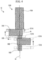
- the respective rotor separate bodies 131A When installing the respective rotor separate bodies 131A, as shown in FIG. 4 , the respective rotor separate bodies 131A are inserted through the shaft main body 16H from an one side in the direction of the axis O. That is, the rotor separate bodies 131A are inserted from the third shaft portion 16C side.
- the rotor separate bodies 131A are further moved upward (to the other side in the direction of the axis O) and pass through the second eccentric shaft portion 14B.
- the rotor separate bodies 131A can pass through the second eccentric shaft portion 14B smoothly.
- the rotor separate bodies 131A which have passed through the second eccentric shaft portion 14B are moved to the same position as the second shaft portion 16B in the direction of the axis O. Thereafter, the rotor separate bodies 131A are moved in a direction orthogonal to the axis O. Specifically, as shown in FIG. 4 , the rotor separate bodies 131A are moved in the eccentric direction of the first eccentric shaft portion 14A, and an axial center of the respective rotor separate bodies 131A and an axial center of the first eccentric shaft portion 14A coincide with each other. From this state, the rotor separate bodies 131A are moved upward.
- the above-described processes are repeatedly performed for each of the plurality (three) of rotor separate bodies 131A. Thereafter, the plurality of rotor separate bodies 131A are in contact with each other in a state in which they can move relative to each other in the peripheral direction and the radial direction. Thereby, the first rotor installation process S2 is completed.
- a second rotor installation process S3 is performed.
- the annular second piston rotor 13B formed as one member is fitted from the third shaft portion 16C side to the outer peripheral side of the second eccentric shaft portion 14B. Accordingly, all the processes of the assembling method of the crankshaft according to this embodiment are completed.
- the motor 18 is driven by external power supply.
- the shaft main body 16H rotates around the axis O.
- the first eccentric shaft portion 14A and the second eccentric shaft portion 14B revolve around a central axis (the axis O) of the shaft main body 16H.
- the first piston rotor 13A and the second piston rotor 13B eccentrically rotate in the compression chambers R1 and R2 to follow this revolution.
- deflection may occur in the shaft main body 16H in accordance with continuous operation of the compressor system 100.
- a length (a length in the direction of the axis O) of the shaft main body 16H is longer than that in a single rotary compressor having only one cylinder.
- deflection of the shaft main body 16H easily occurs between the upper bearing portion 17A and the lower bearing portion 17B.
- the first eccentric shaft portion 14A formed in the vicinity of a center of the shaft main body 16H in the direction of the axis O may be inclined, and the first piston rotor 13A may come into partial contact with the first eccentric shaft portion 14A.
- stress generated in the first eccentric shaft portion 14A by the first piston rotor 13A may partially increase, and a friction loss in the shaft main body 16H may increase. In addition, this may lead to an increase in noise and vibration.
- the first piston rotor 13A is constituted by the plurality of rotor separate bodies 131A which can move relative to each other in a state in which they are in contact with each other in the direction of the axis O. That is, the first piston rotor 13A is divided into a plurality of parts in the direction of the axis O. Therefore, even when the shaft main body 16H is bent and the first eccentric shaft portion 14A is inclined, a position of each of the rotor separate bodies 131A in the radial direction is shifted to follow the inclination of the first eccentric shaft portion 14A.
- a region of the first piston rotor 13A in contact with the first eccentric shaft portion 14A increases, and an influence of the partial contact can be minimized.
- the friction loss between the first piston rotor 13A and the first eccentric shaft portion 14A can be reduced.
- performance of the compressor 10 due to the deflection of the crankshaft 16 can be further improved.
- the reliability of the crankshaft 16 and the reliability of the compressor 10 can be improved.
- the first piston rotor 13A in installing the first piston rotor 13A on the first eccentric shaft portion 14A, a process in which the annular first piston rotor 13A is inserted through the shaft main body 16H from an end thereof in the direction of the axis O is performed.
- the first eccentric shaft portion 14A is disposed to be partially recessed outward in the radial direction with respect to the first shaft portion 16A and the retracted portion Ar is formed, the first piston rotor 13A cannot be inserted from the first shaft portion 16A side in the direction of the axis O. Therefore, it is necessary to pass the first piston rotor 13A from the one side in the direction of the axis O in the order of the third shaft portion 16C and the second shaft portion 16B.
- the first piston rotor when the first piston rotor is integrally formed and the length of the first piston rotor in the direction of the axis O is larger than the length of the second shaft portion 16B, since the second shaft portion 16B and the second eccentric shaft portion 14B interfere with each other, the first piston rotor cannot reach the first eccentric shaft portion 14A and cannot be correctly installed.
- the plurality of rotor separate bodies 131A have the same lengths in the direction of the axis O, and the length of each of the rotor separate bodies 131A in the direction of the axis O is set equal to or less than the length of the second shaft portion 16B. Therefore, the axial center of the first eccentric shaft portion 14A and the axial center of the respective rotor separate bodies 131A can be made to coincide with each other by moving the rotor separate bodies 131A from the third shaft portion 16C side in the direction of the axis O to a position of the second shaft portion 16B and moving the rotor separate bodies 131A in the radial direction.
- the plurality of rotor separate bodies 131A can be smoothly fitted to the first eccentric shaft portion 14A. Therefore, because the plurality of rotor separate bodies 131A are independent of each other, assemblability when the first piston rotor 13A is installed at the shaft main body 16H can be improved, as compared to the case in which the first piston rotor is integrally formed or the case in which the rotor separate bodies 131A are partially connected. Furthermore, the length of the second shaft portion 16B in the direction of the axis O can be reduced regardless of a length of the entire first piston rotor 13A in the direction of the axis O. Thus, the length of the shaft main body 16H in the direction of the axis O can be reduced as a whole. As a result, the rigidity of the shaft main body 16H increases, and the likelihood of deflection can be reduced. That is, according to the above-described constitution and the assembling method, the compressor 10 with improved performance can be provided more simply.
- first piston rotor 13A can be easily formed by forming the first piston rotor 13A with the rotor separate bodies 131A having the same shape instead of different shapes.
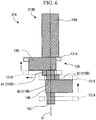
- a second shaft portion 216B of a crankshaft 216 has a second shaft portion main body 40, a first reinforcing portion 41, and a second reinforcing portion 42.
- the second shaft main body 40 extends along the axis O and is integrally installed on one side of the first eccentric shaft portion 14A in the direction of the axis O.
- the second shaft portion main body 40 has a smaller radial length than the first shaft portion 16A.
- the second shaft portion main body 40 is formed so that a length of the second shaft portion main body 40 in the direction of the axis O which is disposed coaxially with the first shaft portion 16A is substantially the same as the length of the third shaft portion 16C in the direction of the axis O. That is, the length of the second shaft portion main body 40 in the direction of the axis O is longer than that of the second shaft portion 16B of the first embodiment. In other words, it is formed longer than the length of the respective rotor separate bodies 131A in the direction of the axis O.
- the first reinforcing portion 41 is provided at a position in which a gap is not formed in the direction of the axis O with respect to the first eccentric shaft portion 14A.
- the first reinforcing portion 41 is eccentric in the same direction as the eccentric direction of the first eccentric shaft portion 14A.
- the first reinforcing portion 41 is integrally formed of the same material with respect to the second shaft portion main body 40 and the first eccentric shaft portion 14A.
- An end surface (a lower surface A1 of a compensating portion) of the first reinforcing portion 41 on one side in the direction of the axis O faces an end surface (an upper surface A2 of the eccentric shaft portion) of the second eccentric shaft portion 14B on the other side of the direction of the axis O with a gap G1.
- a length of the gap G1 in the direction of the axis O is slightly larger than the length of the respective rotor separate bodies 131A in the direction of the axis O.
- the second reinforcing portion 42 is provided at a position in which a gap is not formed in the direction of the axis O with respect to the second eccentric shaft portion 14B.
- the second reinforcing portion 42 is eccentric in the same direction as the eccentric direction of the second eccentric shaft portion 14B. That is, the second reinforcing portion 42 is eccentric in a direction opposite to the eccentric direction of the first eccentric shaft portion 14A and the first reinforcing portion 41.
- the second reinforcing portion 42 is integrally formed of the same material with respect to the second shaft portion main body 40 and the second eccentric shaft portion 14B.
- An end surface (an upper surface A3 of the compensating portion) of the second reinforcing portion 42 on the other side in the direction of the axis O faces an end surface (a lower surface A4 of the eccentric shaft portion) of the first eccentric shaft portion 14A on one side of the direction of the axis O with a gap G2.
- a length of the gap G2 in the direction of the axis O is slightly larger than the length of the rotor separate bodies 131A in the direction of the axis O.
- the first piston rotor 13A is installed at the crankshaft 216 having such a constitution through the processes as shown in FIG. 6 .
- the rotor separate bodies 131A are inserted from the third shaft portion 16C side in the direction of the axis O and moved upward.
- the respective rotor separate bodies 131A reach the same position as the second reinforcing portion 42 in the direction of the axis O, the respective rotor separate bodies 131A are moved in a direction (the radial direction) orthogonal to the axis O.
- the respective rotor separate bodies 131A are moved in the same direction as the eccentric direction of the first reinforcing portion 41 and the first eccentric shaft portion 14A. From this state, the respective rotor separate bodies 131A are further moved upward.
- the respective rotor separate bodies 131A reach the same position as the first reinforcing portion 41 in the direction of the axis O, the respective rotor separate bodies 131A are further moved in the direction orthogonal to the axis O, and the axial center of the respective rotor separate bodies 131A and the axial center of the first eccentric shaft portion 14A coincide with each other. From this state, the rotor separate bodies 131A are further moved upward and fitted to the first eccentric shaft portion 14A.
- the first piston rotor 13A is installed at the crankshaft 216 by repeating this process for the number of rotor separate bodies 131A.
- the region of the first piston rotor 13A in contact with respect to the first eccentric shaft portion 14A is increased by the plurality of rotor separate bodies 131A, and the influence of the partial contact can be minimized.
- the friction loss between the first piston rotor 13A and the first eccentric shaft portion 14A can be reduced.
- the performance of the compressor 10 can be further improved.
- the first reinforcing portion 41 and the second reinforcing portion 42 are provided on the second shaft portion 216B. Accordingly, a large length of the second shaft portion 216B in the radial direction can be secured. As a result, the rigidity of the second shaft portion 216B as a whole can be increased, and the deflection of the crankshaft 216 can be reduced.
- each of the first reinforcing portion 41 and the second reinforcing portion 42 are eccentric with respect to the axis O. Furthermore, a separation distance in the direction of the axis O between the lower surface A1 of the compensating portion and the upper surface A2 of the eccentric shaft portion is slightly larger than the length of the respective rotor separate bodies 131A in the direction of the axis O. Further, the separation distance in the direction of the axis O between the upper surface A3 of the compensating portion and the lower surface A4 of the eccentric shaft portion is slightly larger than the length of the respective rotor separate bodies 131A in the direction of the axis O. Therefore, as shown in FIG.
- the rotor separate bodies 131A when the rotor separate bodies 131A are installed, the rotor separate bodies 131A can smoothly pass through the second eccentric shaft portion 14B. Therefore, since the first piston rotor 13A is equally divided, it is possible to secure the large length of the first piston rotor 13A in the direction of the axis O while forming a region in which the length in the radial direction is enlarged to secure the rigidity of the second shaft portion 216B without assembly restrictions. As a result, the compressor 10 with improved performance can be provided more simply.
- the example in which the second piston rotor 13B is integrally formed in the direction of the axis O has been described.
- first piston rotor 13A is not limited to the constitution in which it is formed by the rotor separate bodies 131A having the same shape as in the embodiment.
- the first piston rotor 13A may be constituted by rotor separate bodies having different lengths in the direction of the axis O.
Landscapes
- Engineering & Computer Science (AREA)
- Mechanical Engineering (AREA)
- General Engineering & Computer Science (AREA)
- Applications Or Details Of Rotary Compressors (AREA)
Applications Claiming Priority (1)
| Application Number | Priority Date | Filing Date | Title |
|---|---|---|---|
| JP2018079336A JP7063699B2 (ja) | 2018-04-17 | 2018-04-17 | クランクシャフト、ロータリー圧縮機、及びクランクシャフトの組立方法 |
Publications (2)
| Publication Number | Publication Date |
|---|---|
| EP3557067A1 true EP3557067A1 (de) | 2019-10-23 |
| EP3557067B1 EP3557067B1 (de) | 2021-12-29 |
Family
ID=66182429
Family Applications (1)
| Application Number | Title | Priority Date | Filing Date |
|---|---|---|---|
| EP19169260.7A Active EP3557067B1 (de) | 2018-04-17 | 2019-04-15 | Kolbenrotor, kurbelwelle, rotationsverdichter und verfahren zur montage der kurbelwelle |
Country Status (2)
| Country | Link |
|---|---|
| EP (1) | EP3557067B1 (de) |
| JP (1) | JP7063699B2 (de) |
Citations (5)
| Publication number | Priority date | Publication date | Assignee | Title |
|---|---|---|---|---|
| WO2005124156A1 (ja) * | 2004-06-15 | 2005-12-29 | Toshiba Carrier Corporation | 多気筒形回転式圧縮機 |
| JP2010223034A (ja) | 2009-03-23 | 2010-10-07 | Daikin Ind Ltd | 圧縮機 |
| CN103711699A (zh) * | 2012-10-01 | 2014-04-09 | 三菱电机株式会社 | 旋转压缩机 |
| JP2014231752A (ja) * | 2013-05-28 | 2014-12-11 | 東芝キヤリア株式会社 | ロータリコンプレッサ及び冷凍サイクル装置 |
| CN105840516A (zh) * | 2016-05-06 | 2016-08-10 | 宁波甬微集团有限公司 | 一种压缩机用滚动活塞 |
Family Cites Families (5)
| Publication number | Priority date | Publication date | Assignee | Title |
|---|---|---|---|---|
| JPH0427791A (ja) * | 1990-05-22 | 1992-01-30 | Matsushita Refrig Co Ltd | 冷媒ガス回転圧縮機 |
| JP2003328972A (ja) | 2002-05-09 | 2003-11-19 | Hitachi Home & Life Solutions Inc | 密閉形2シリンダロータリ圧縮機及びその製造方法 |
| JP4488104B2 (ja) | 2008-01-23 | 2010-06-23 | ダイキン工業株式会社 | 圧縮機 |
| US10233929B2 (en) | 2014-06-24 | 2019-03-19 | Panasonic Intellectual Property Management Co., Ltd. | Rotary compressor having two cylinders |
| JP2017141802A (ja) | 2016-02-12 | 2017-08-17 | 東芝キヤリア株式会社 | 回転式圧縮機および冷凍サイクル装置 |
-
2018
- 2018-04-17 JP JP2018079336A patent/JP7063699B2/ja active Active
-
2019
- 2019-04-15 EP EP19169260.7A patent/EP3557067B1/de active Active
Patent Citations (5)
| Publication number | Priority date | Publication date | Assignee | Title |
|---|---|---|---|---|
| WO2005124156A1 (ja) * | 2004-06-15 | 2005-12-29 | Toshiba Carrier Corporation | 多気筒形回転式圧縮機 |
| JP2010223034A (ja) | 2009-03-23 | 2010-10-07 | Daikin Ind Ltd | 圧縮機 |
| CN103711699A (zh) * | 2012-10-01 | 2014-04-09 | 三菱电机株式会社 | 旋转压缩机 |
| JP2014231752A (ja) * | 2013-05-28 | 2014-12-11 | 東芝キヤリア株式会社 | ロータリコンプレッサ及び冷凍サイクル装置 |
| CN105840516A (zh) * | 2016-05-06 | 2016-08-10 | 宁波甬微集团有限公司 | 一种压缩机用滚动活塞 |
Also Published As
| Publication number | Publication date |
|---|---|
| JP2019183818A (ja) | 2019-10-24 |
| EP3557067B1 (de) | 2021-12-29 |
| JP7063699B2 (ja) | 2022-05-09 |
Similar Documents
| Publication | Publication Date | Title |
|---|---|---|
| US11732714B2 (en) | Scroll compressor including bushing mounted on eccentric shaft containing cylindrical and auxiliary weight portions and balancer disposed above annular rotor remote from back pressure chamber | |
| JP6187266B2 (ja) | 電動圧縮機 | |
| EP3239526B1 (de) | Elektrisch betriebener spiralverdichter | |
| US10393117B2 (en) | Scroll compressor | |
| US9145890B2 (en) | Rotary compressor with dual eccentric portion | |
| EP3940230B1 (de) | Verdichter | |
| US20150159652A1 (en) | Scroll-type compressor | |
| US10087934B2 (en) | Vane compressor | |
| US9885359B2 (en) | Motor-driven compressor | |
| EP3557067B1 (de) | Kolbenrotor, kurbelwelle, rotationsverdichter und verfahren zur montage der kurbelwelle | |
| EP3550147A1 (de) | Verdichtersystem | |
| WO2019026410A1 (ja) | オルダムリング、スクロール圧縮機 | |
| EP3572670B1 (de) | Spiralverdichter | |
| US11965508B2 (en) | Scroll compressor | |
| CN115929628B (zh) | 涡旋型压缩机 | |
| EP3550146B1 (de) | Verdichtersystem | |
| EP4273401B1 (de) | Spiralverdichter | |
| CN112780548B (zh) | 具有压配合式电动机和竖直中央吸入口的涡旋压缩机 | |
| JP2019094844A (ja) | ロータリ圧縮機 | |
| WO2025009142A1 (ja) | スクロール式流体機械のメンテナンス方法及びスクロール式流体機械 | |
| CN118974404A (zh) | 双旋转式涡旋型压缩机 | |
| JP2013253554A (ja) | 二段スクロール圧縮機 | |
| KR20060087260A (ko) | 복식 로터리 압축기의 압축기구부 조립 구조 | |
| JP2020193567A (ja) | ロータリ圧縮機 | |
| KR20200140428A (ko) | 스크롤형 압축기 |
Legal Events
| Date | Code | Title | Description |
|---|---|---|---|
| PUAI | Public reference made under article 153(3) epc to a published international application that has entered the european phase |
Free format text: ORIGINAL CODE: 0009012 |
|
| STAA | Information on the status of an ep patent application or granted ep patent |
Free format text: STATUS: THE APPLICATION HAS BEEN PUBLISHED |
|
| AK | Designated contracting states |
Kind code of ref document: A1 Designated state(s): AL AT BE BG CH CY CZ DE DK EE ES FI FR GB GR HR HU IE IS IT LI LT LU LV MC MK MT NL NO PL PT RO RS SE SI SK SM TR |
|
| AX | Request for extension of the european patent |
Extension state: BA ME |
|
| STAA | Information on the status of an ep patent application or granted ep patent |
Free format text: STATUS: REQUEST FOR EXAMINATION WAS MADE |
|
| 17P | Request for examination filed |
Effective date: 20200423 |
|
| RBV | Designated contracting states (corrected) |
Designated state(s): AL AT BE BG CH CY CZ DE DK EE ES FI FR GB GR HR HU IE IS IT LI LT LU LV MC MK MT NL NO PL PT RO RS SE SI SK SM TR |
|
| STAA | Information on the status of an ep patent application or granted ep patent |
Free format text: STATUS: EXAMINATION IS IN PROGRESS |
|
| RIC1 | Information provided on ipc code assigned before grant |
Ipc: F04C 23/00 20060101ALN20200525BHEP Ipc: F04C 29/00 20060101AFI20200525BHEP Ipc: F04C 18/34 20060101ALI20200525BHEP |
|
| 17Q | First examination report despatched |
Effective date: 20200625 |
|
| RIC1 | Information provided on ipc code assigned before grant |
Ipc: F04C 23/00 20060101ALN20210624BHEP Ipc: F04C 18/34 20060101ALI20210624BHEP Ipc: F04C 29/00 20060101AFI20210624BHEP |
|
| RIC1 | Information provided on ipc code assigned before grant |
Ipc: F04C 23/00 20060101ALN20210708BHEP Ipc: F04C 18/34 20060101ALI20210708BHEP Ipc: F04C 29/00 20060101AFI20210708BHEP |
|
| GRAP | Despatch of communication of intention to grant a patent |
Free format text: ORIGINAL CODE: EPIDOSNIGR1 |
|
| STAA | Information on the status of an ep patent application or granted ep patent |
Free format text: STATUS: GRANT OF PATENT IS INTENDED |
|
| INTG | Intention to grant announced |
Effective date: 20210823 |
|
| GRAS | Grant fee paid |
Free format text: ORIGINAL CODE: EPIDOSNIGR3 |
|
| GRAA | (expected) grant |
Free format text: ORIGINAL CODE: 0009210 |
|
| STAA | Information on the status of an ep patent application or granted ep patent |
Free format text: STATUS: THE PATENT HAS BEEN GRANTED |
|
| AK | Designated contracting states |
Kind code of ref document: B1 Designated state(s): AL AT BE BG CH CY CZ DE DK EE ES FI FR GB GR HR HU IE IS IT LI LT LU LV MC MK MT NL NO PL PT RO RS SE SI SK SM TR |
|
| REG | Reference to a national code |
Ref country code: GB Ref legal event code: FG4D |
|
| REG | Reference to a national code |
Ref country code: CH Ref legal event code: EP |
|
| REG | Reference to a national code |
Ref country code: DE Ref legal event code: R096 Ref document number: 602019010366 Country of ref document: DE |
|
| REG | Reference to a national code |
Ref country code: AT Ref legal event code: REF Ref document number: 1458881 Country of ref document: AT Kind code of ref document: T Effective date: 20220115 |
|
| REG | Reference to a national code |
Ref country code: IE Ref legal event code: FG4D |
|
| REG | Reference to a national code |
Ref country code: LT Ref legal event code: MG9D |
|
| PG25 | Lapsed in a contracting state [announced via postgrant information from national office to epo] |
Ref country code: RS Free format text: LAPSE BECAUSE OF FAILURE TO SUBMIT A TRANSLATION OF THE DESCRIPTION OR TO PAY THE FEE WITHIN THE PRESCRIBED TIME-LIMIT Effective date: 20211229 Ref country code: LT Free format text: LAPSE BECAUSE OF FAILURE TO SUBMIT A TRANSLATION OF THE DESCRIPTION OR TO PAY THE FEE WITHIN THE PRESCRIBED TIME-LIMIT Effective date: 20211229 Ref country code: FI Free format text: LAPSE BECAUSE OF FAILURE TO SUBMIT A TRANSLATION OF THE DESCRIPTION OR TO PAY THE FEE WITHIN THE PRESCRIBED TIME-LIMIT Effective date: 20211229 Ref country code: BG Free format text: LAPSE BECAUSE OF FAILURE TO SUBMIT A TRANSLATION OF THE DESCRIPTION OR TO PAY THE FEE WITHIN THE PRESCRIBED TIME-LIMIT Effective date: 20220329 |
|
| REG | Reference to a national code |
Ref country code: NL Ref legal event code: MP Effective date: 20211229 |
|
| REG | Reference to a national code |
Ref country code: AT Ref legal event code: MK05 Ref document number: 1458881 Country of ref document: AT Kind code of ref document: T Effective date: 20211229 |
|
| PG25 | Lapsed in a contracting state [announced via postgrant information from national office to epo] |
Ref country code: SE Free format text: LAPSE BECAUSE OF FAILURE TO SUBMIT A TRANSLATION OF THE DESCRIPTION OR TO PAY THE FEE WITHIN THE PRESCRIBED TIME-LIMIT Effective date: 20211229 Ref country code: NO Free format text: LAPSE BECAUSE OF FAILURE TO SUBMIT A TRANSLATION OF THE DESCRIPTION OR TO PAY THE FEE WITHIN THE PRESCRIBED TIME-LIMIT Effective date: 20220329 Ref country code: LV Free format text: LAPSE BECAUSE OF FAILURE TO SUBMIT A TRANSLATION OF THE DESCRIPTION OR TO PAY THE FEE WITHIN THE PRESCRIBED TIME-LIMIT Effective date: 20211229 Ref country code: HR Free format text: LAPSE BECAUSE OF FAILURE TO SUBMIT A TRANSLATION OF THE DESCRIPTION OR TO PAY THE FEE WITHIN THE PRESCRIBED TIME-LIMIT Effective date: 20211229 Ref country code: GR Free format text: LAPSE BECAUSE OF FAILURE TO SUBMIT A TRANSLATION OF THE DESCRIPTION OR TO PAY THE FEE WITHIN THE PRESCRIBED TIME-LIMIT Effective date: 20220330 |
|
| PG25 | Lapsed in a contracting state [announced via postgrant information from national office to epo] |
Ref country code: NL Free format text: LAPSE BECAUSE OF FAILURE TO SUBMIT A TRANSLATION OF THE DESCRIPTION OR TO PAY THE FEE WITHIN THE PRESCRIBED TIME-LIMIT Effective date: 20211229 |
|
| PG25 | Lapsed in a contracting state [announced via postgrant information from national office to epo] |
Ref country code: SM Free format text: LAPSE BECAUSE OF FAILURE TO SUBMIT A TRANSLATION OF THE DESCRIPTION OR TO PAY THE FEE WITHIN THE PRESCRIBED TIME-LIMIT Effective date: 20211229 Ref country code: SK Free format text: LAPSE BECAUSE OF FAILURE TO SUBMIT A TRANSLATION OF THE DESCRIPTION OR TO PAY THE FEE WITHIN THE PRESCRIBED TIME-LIMIT Effective date: 20211229 Ref country code: RO Free format text: LAPSE BECAUSE OF FAILURE TO SUBMIT A TRANSLATION OF THE DESCRIPTION OR TO PAY THE FEE WITHIN THE PRESCRIBED TIME-LIMIT Effective date: 20211229 Ref country code: PT Free format text: LAPSE BECAUSE OF FAILURE TO SUBMIT A TRANSLATION OF THE DESCRIPTION OR TO PAY THE FEE WITHIN THE PRESCRIBED TIME-LIMIT Effective date: 20220429 Ref country code: ES Free format text: LAPSE BECAUSE OF FAILURE TO SUBMIT A TRANSLATION OF THE DESCRIPTION OR TO PAY THE FEE WITHIN THE PRESCRIBED TIME-LIMIT Effective date: 20211229 Ref country code: EE Free format text: LAPSE BECAUSE OF FAILURE TO SUBMIT A TRANSLATION OF THE DESCRIPTION OR TO PAY THE FEE WITHIN THE PRESCRIBED TIME-LIMIT Effective date: 20211229 Ref country code: CZ Free format text: LAPSE BECAUSE OF FAILURE TO SUBMIT A TRANSLATION OF THE DESCRIPTION OR TO PAY THE FEE WITHIN THE PRESCRIBED TIME-LIMIT Effective date: 20211229 |
|
| PG25 | Lapsed in a contracting state [announced via postgrant information from national office to epo] |
Ref country code: PL Free format text: LAPSE BECAUSE OF FAILURE TO SUBMIT A TRANSLATION OF THE DESCRIPTION OR TO PAY THE FEE WITHIN THE PRESCRIBED TIME-LIMIT Effective date: 20211229 Ref country code: AT Free format text: LAPSE BECAUSE OF FAILURE TO SUBMIT A TRANSLATION OF THE DESCRIPTION OR TO PAY THE FEE WITHIN THE PRESCRIBED TIME-LIMIT Effective date: 20211229 |
|
| PG25 | Lapsed in a contracting state [announced via postgrant information from national office to epo] |
Ref country code: IS Free format text: LAPSE BECAUSE OF FAILURE TO SUBMIT A TRANSLATION OF THE DESCRIPTION OR TO PAY THE FEE WITHIN THE PRESCRIBED TIME-LIMIT Effective date: 20220429 |
|
| REG | Reference to a national code |
Ref country code: DE Ref legal event code: R097 Ref document number: 602019010366 Country of ref document: DE |
|
| PG25 | Lapsed in a contracting state [announced via postgrant information from national office to epo] |
Ref country code: DK Free format text: LAPSE BECAUSE OF FAILURE TO SUBMIT A TRANSLATION OF THE DESCRIPTION OR TO PAY THE FEE WITHIN THE PRESCRIBED TIME-LIMIT Effective date: 20211229 Ref country code: AL Free format text: LAPSE BECAUSE OF FAILURE TO SUBMIT A TRANSLATION OF THE DESCRIPTION OR TO PAY THE FEE WITHIN THE PRESCRIBED TIME-LIMIT Effective date: 20211229 |
|
| PLBE | No opposition filed within time limit |
Free format text: ORIGINAL CODE: 0009261 |
|
| STAA | Information on the status of an ep patent application or granted ep patent |
Free format text: STATUS: NO OPPOSITION FILED WITHIN TIME LIMIT |
|
| REG | Reference to a national code |
Ref country code: CH Ref legal event code: PL |
|
| 26N | No opposition filed |
Effective date: 20220930 |
|
| REG | Reference to a national code |
Ref country code: BE Ref legal event code: MM Effective date: 20220430 |
|
| PG25 | Lapsed in a contracting state [announced via postgrant information from national office to epo] |
Ref country code: MC Free format text: LAPSE BECAUSE OF FAILURE TO SUBMIT A TRANSLATION OF THE DESCRIPTION OR TO PAY THE FEE WITHIN THE PRESCRIBED TIME-LIMIT Effective date: 20211229 Ref country code: LU Free format text: LAPSE BECAUSE OF NON-PAYMENT OF DUE FEES Effective date: 20220415 Ref country code: LI Free format text: LAPSE BECAUSE OF NON-PAYMENT OF DUE FEES Effective date: 20220430 Ref country code: CH Free format text: LAPSE BECAUSE OF NON-PAYMENT OF DUE FEES Effective date: 20220430 |
|
| PG25 | Lapsed in a contracting state [announced via postgrant information from national office to epo] |
Ref country code: SI Free format text: LAPSE BECAUSE OF FAILURE TO SUBMIT A TRANSLATION OF THE DESCRIPTION OR TO PAY THE FEE WITHIN THE PRESCRIBED TIME-LIMIT Effective date: 20211229 Ref country code: BE Free format text: LAPSE BECAUSE OF NON-PAYMENT OF DUE FEES Effective date: 20220430 |
|
| REG | Reference to a national code |
Ref country code: DE Ref legal event code: R082 Ref document number: 602019010366 Country of ref document: DE Representative=s name: CBDL PATENTANWAELTE GBR, DE Ref country code: DE Ref legal event code: R082 Ref document number: 602019010366 Country of ref document: DE Representative=s name: CBDL PATENTANWAELTE EGBR, DE |
|
| PG25 | Lapsed in a contracting state [announced via postgrant information from national office to epo] |
Ref country code: IE Free format text: LAPSE BECAUSE OF NON-PAYMENT OF DUE FEES Effective date: 20220415 |
|
| PG25 | Lapsed in a contracting state [announced via postgrant information from national office to epo] |
Ref country code: IT Free format text: LAPSE BECAUSE OF FAILURE TO SUBMIT A TRANSLATION OF THE DESCRIPTION OR TO PAY THE FEE WITHIN THE PRESCRIBED TIME-LIMIT Effective date: 20211229 |
|
| PG25 | Lapsed in a contracting state [announced via postgrant information from national office to epo] |
Ref country code: HU Free format text: LAPSE BECAUSE OF FAILURE TO SUBMIT A TRANSLATION OF THE DESCRIPTION OR TO PAY THE FEE WITHIN THE PRESCRIBED TIME-LIMIT; INVALID AB INITIO Effective date: 20190415 |
|
| PG25 | Lapsed in a contracting state [announced via postgrant information from national office to epo] |
Ref country code: MK Free format text: LAPSE BECAUSE OF FAILURE TO SUBMIT A TRANSLATION OF THE DESCRIPTION OR TO PAY THE FEE WITHIN THE PRESCRIBED TIME-LIMIT Effective date: 20211229 Ref country code: CY Free format text: LAPSE BECAUSE OF FAILURE TO SUBMIT A TRANSLATION OF THE DESCRIPTION OR TO PAY THE FEE WITHIN THE PRESCRIBED TIME-LIMIT Effective date: 20211229 |
|
| PG25 | Lapsed in a contracting state [announced via postgrant information from national office to epo] |
Ref country code: MT Free format text: LAPSE BECAUSE OF FAILURE TO SUBMIT A TRANSLATION OF THE DESCRIPTION OR TO PAY THE FEE WITHIN THE PRESCRIBED TIME-LIMIT Effective date: 20211229 |
|
| PGFP | Annual fee paid to national office [announced via postgrant information from national office to epo] |
Ref country code: DE Payment date: 20250305 Year of fee payment: 7 |
|
| PG25 | Lapsed in a contracting state [announced via postgrant information from national office to epo] |
Ref country code: TR Free format text: LAPSE BECAUSE OF FAILURE TO SUBMIT A TRANSLATION OF THE DESCRIPTION OR TO PAY THE FEE WITHIN THE PRESCRIBED TIME-LIMIT Effective date: 20211229 |
|
| PGFP | Annual fee paid to national office [announced via postgrant information from national office to epo] |
Ref country code: GB Payment date: 20260313 Year of fee payment: 8 |
|
| PGFP | Annual fee paid to national office [announced via postgrant information from national office to epo] |
Ref country code: FR Payment date: 20260309 Year of fee payment: 8 |