EP3556980B1 - Scharnier zur kontrolle von geneigten türen oder türblättern - Google Patents
Scharnier zur kontrolle von geneigten türen oder türblättern Download PDFInfo
- Publication number
- EP3556980B1 EP3556980B1 EP19169402.5A EP19169402A EP3556980B1 EP 3556980 B1 EP3556980 B1 EP 3556980B1 EP 19169402 A EP19169402 A EP 19169402A EP 3556980 B1 EP3556980 B1 EP 3556980B1
- Authority
- EP
- European Patent Office
- Prior art keywords
- section
- hinge
- axis
- rotation
- closing
- Prior art date
- Legal status (The legal status is an assumption and is not a legal conclusion. Google has not performed a legal analysis and makes no representation as to the accuracy of the status listed.)
- Active
Links
Images


Classifications
-
- E—FIXED CONSTRUCTIONS
- E05—LOCKS; KEYS; WINDOW OR DOOR FITTINGS; SAFES
- E05F—DEVICES FOR MOVING WINGS INTO OPEN OR CLOSED POSITION; CHECKS FOR WINGS; WING FITTINGS NOT OTHERWISE PROVIDED FOR, CONCERNED WITH THE FUNCTIONING OF THE WING
- E05F1/00—Closers or openers for wings, not otherwise provided for in this subclass
- E05F1/08—Closers or openers for wings, not otherwise provided for in this subclass spring-actuated, e.g. for horizontally sliding wings
- E05F1/10—Closers or openers for wings, not otherwise provided for in this subclass spring-actuated, e.g. for horizontally sliding wings for swinging wings, e.g. counterbalance
- E05F1/12—Mechanisms in the shape of hinges or pivots, operated by springs
- E05F1/1246—Mechanisms in the shape of hinges or pivots, operated by springs with a coil spring perpendicular to the pivot axis
- E05F1/1253—Mechanisms in the shape of hinges or pivots, operated by springs with a coil spring perpendicular to the pivot axis with a compression spring
- E05F1/1261—Mechanisms in the shape of hinges or pivots, operated by springs with a coil spring perpendicular to the pivot axis with a compression spring for counterbalancing
-
- E—FIXED CONSTRUCTIONS
- E05—LOCKS; KEYS; WINDOW OR DOOR FITTINGS; SAFES
- E05F—DEVICES FOR MOVING WINGS INTO OPEN OR CLOSED POSITION; CHECKS FOR WINGS; WING FITTINGS NOT OTHERWISE PROVIDED FOR, CONCERNED WITH THE FUNCTIONING OF THE WING
- E05F1/00—Closers or openers for wings, not otherwise provided for in this subclass
- E05F1/02—Closers or openers for wings, not otherwise provided for in this subclass gravity-actuated, e.g. by use of counterweights
- E05F1/04—Closers or openers for wings, not otherwise provided for in this subclass gravity-actuated, e.g. by use of counterweights for wings which lift during movement, operated by their own weight
- E05F1/06—Mechanisms in the shape of hinges or pivots, operated by the weight of the wing
- E05F1/068—Mechanisms in the shape of hinges or pivots, operated by the weight of the wing with inclined pivot-axes
-
- E—FIXED CONSTRUCTIONS
- E05—LOCKS; KEYS; WINDOW OR DOOR FITTINGS; SAFES
- E05F—DEVICES FOR MOVING WINGS INTO OPEN OR CLOSED POSITION; CHECKS FOR WINGS; WING FITTINGS NOT OTHERWISE PROVIDED FOR, CONCERNED WITH THE FUNCTIONING OF THE WING
- E05F3/00—Closers or openers with braking devices, e.g. checks; Construction of pneumatic or liquid braking devices
- E05F3/20—Closers or openers with braking devices, e.g. checks; Construction of pneumatic or liquid braking devices in hinges
-
- E—FIXED CONSTRUCTIONS
- E05—LOCKS; KEYS; WINDOW OR DOOR FITTINGS; SAFES
- E05Y—INDEXING SCHEME ASSOCIATED WITH SUBCLASSES E05D AND E05F, RELATING TO CONSTRUCTION ELEMENTS, ELECTRIC CONTROL, POWER SUPPLY, POWER SIGNAL OR TRANSMISSION, USER INTERFACES, MOUNTING OR COUPLING, DETAILS, ACCESSORIES, AUXILIARY OPERATIONS NOT OTHERWISE PROVIDED FOR, APPLICATION THEREOF
- E05Y2201/00—Constructional elements; Accessories therefor
- E05Y2201/60—Suspension or transmission members; Accessories therefor
- E05Y2201/622—Suspension or transmission members elements
- E05Y2201/638—Cams; Ramps
-
- E—FIXED CONSTRUCTIONS
- E05—LOCKS; KEYS; WINDOW OR DOOR FITTINGS; SAFES
- E05Y—INDEXING SCHEME ASSOCIATED WITH SUBCLASSES E05D AND E05F, RELATING TO CONSTRUCTION ELEMENTS, ELECTRIC CONTROL, POWER SUPPLY, POWER SIGNAL OR TRANSMISSION, USER INTERFACES, MOUNTING OR COUPLING, DETAILS, ACCESSORIES, AUXILIARY OPERATIONS NOT OTHERWISE PROVIDED FOR, APPLICATION THEREOF
- E05Y2900/00—Application of doors, windows, wings or fittings thereof
- E05Y2900/30—Application of doors, windows, wings or fittings thereof for domestic appliances
- E05Y2900/31—Application of doors, windows, wings or fittings thereof for domestic appliances for refrigerators
Definitions
- the present invention generally regards the technical field of hinges, and it particularly regards a control hinge, in particular for doors, door-leaves and the like of the inclined type.
- the glass door-leaves of refrigerators for the large-scale distribution, such as supermarkets or hypermarkets are relatively heavy, about 20 - 25 kg.
- the door-leaf is particularly heavy to open.
- An object of the present invention is to overcome the aforementioned drawbacks, by providing a control hinge for inclined doors that is highly efficient and relatively economic.
- Another object of the invention is to provide a hinge that allows to control the inclined door-leaf for the entire angular rotation from the opening position to the closing position.
- Another object of the invention is to provide a hinge that allows to have a substantially constant closing speed of the inclined door-leaf for the entire angular rotation from the opening position to the closing position.
- Another object of the invention is to provide a hinge that allows an easy opening of the inclined door-leaf.
- the hinge according to the invention can advantageously be used with closing elements A mounted inclined on a support structure S.
- the hinge 1 may be applied to cold stores with inclined doors, or it can be integrated in the tubular frame thereof.
- the hinge 1 may be applied to glass door-leaves, such as those of a display window or display case.
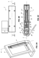
- the hinge 1 is suitable for rotatably coupling a stationary support structure, for example a tubular frame S, and a closing element, for example a door-leaf A, rotatably movable between an opening position, illustrated for example in FIG. 1A , and a closing position, illustrated for example in FIG. 4A , around a rotation axis X.
- a stationary support structure for example a tubular frame S
- a closing element for example a door-leaf A
- the hinge 1 may be a control or hydraulic brake hinge for hydraulically damping the closing displacement of the door-leaf A.
- the hinge 1 includes a hinge body 10, may be substantially sheet-like defining a plane, and a pin 20 defining the rotation axis X.
- closing element A and the stationary support structure S may also rotate around an axis parallel to the axis X without departing from the scope of protection of the attached claims.
- the hinge body 10 may be anchored to the frame S and the pin 20 to the door-leaf A.
- the pin 20 may be movable, while the hinge body 10 may be fixed.
- the pin 20 may be fixed and the hinge body 10 may be movable without departing from the scope of protection of the attached claims.
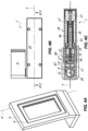
- the hinge body 10 and the pin 20 are mutually coupled to rotate around the axis X between the door-leaf open A, illustrated for example in FIG. 1A , and the door-leaf closed position A, illustrated for example in FIG. 4A .
- the hinge 1 may open in both directions of rotation of the pin 20.
- the hinge may also open in a single direction of rotation without departing from the scope of protection of the attached claims.
- the pin 20 includes a cam element 21 integrally joined thereto interacting with a slider 11 slidable along an axis Y defined by the working chamber 11' inside the hinge body 10.
- Such axis Y may be substantially perpendicular to the axis X. It is clear that the axes X and Y may also be parallel without departing from the scope of protection of the attached claims.
- Such retracted and extended end-stop positions may suitably vary, and not necessarily corresponding to the maximum distal and/or proximal position that can be taken by the slider 11.
- a hydraulic chamber 11" filed with oil or other hydraulic damping fluid may be provided for inside the slider 11.
- the cylinder 60 may divide the hydraulic chamber 11" into a first and a second variable volume compartment 12, 13, placed in fluid communication with each other and preferably adjacent.
- the working fluid may circulate in a hydraulic circuit inside the hydraulic chamber 11", and more in particular it may flow from one to the other of the compartments 12, 13 through a calibrated passage obtained by interference between the hole 14 and valve pin 15.
- Valve means 50 for controlling the through-flow of the working fluid between the two compartments 12, 13 may be present.
- the hydraulic chamber 11' and the relative components therein may define hydraulic damping means, as better outlined hereinafter.
- elastic means 40 mutually interacting with the slider 11 may be provided for inside the hinge body 10.
- the elastic counteracting means may include, respectively may consist of, a spiral spring 40 with predetermined diameter.
- the elastic means 40 may be recovery means, i.e. having a force such to return the slider 11 from the proximal position to the distal position but not closing or opening the door-leaf A.
- recovery elastic means 40 may advantageously be configured and/or dimensioned so as to push the door-leaf A towards the open or closed position, so as to facilitate the user opening or closing the door-leaf A manually.
- the spiral spring 40 may be fitted onto the rod 16, which may possibly serve as a guide for the same.
- the spring 40 will remain interposed between the bottom cap 17 of the hinge body 10 and the rear face 51 of the slider 31, which will act as an abutment face for the spring 40.
- the slider 11 includes a cam follower element 32' with possibly an operative face 32 and thus interacting with the cam element 21 so that the rotation of the latter around the axis X promotes the sliding of the slider along the axis Y .
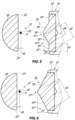
- the cam element 21 may be substantially flat. More in particular, in the initial position for example illustrated in FIG. 1C the substantially flat cam element 21 may be substantially perpendicular to the axis Y , while in the final position illustrated for example in FIG. 4C it may be substantially parallel to the axis Y .
- the operative face 32 may have a suitable shape, which will allow to control the closing of the door-leaf A from the full opening position illustrated for example in FIG. 1A to the closing position illustrated for example in FIG. 4A .
- the door-leaf A may close at a substantially constant speed, thus that is without banging against the frame S.
- the presence of the spring 40 dimensioned as mentioned above will facilitate the opening of the door-leaf A by the user.
- the apparent weight of the opening door-leaf A will be lesser than the actual weight, i.e. the weight that the user would be required to overcome without the spring.
- the operative face 32 has an operative portion 33 with possibly at least one first section 35' and 35".
- the latter may be equal to each other.
- the configuration of the operative face 32 may be symmetrical with respect to the axis Y , so that the hinge 1 behaves in the same way in both directions of rotation of the pin 20.
- the operative face 32 may include a single section 35' or 35" without departing from the scope of protection of the attached claims.
- the sections 35', 35" may be substantially flat and preferably inclined with respect to the axis Y . More in particular, the inclination may be divergent with respect to the axis Y in the direction of the bottom cap 17.
- the operative portion 33 may include a second section 36 interposed between the first sections 35', 35".
- the section 36 may be substantially flat. Thus, it may cooperate with the substantially flat cam element 21 in the initial position so as to keep the hinge in the closed position, for example as illustrated in FIG. 1A .
- the portion 33 which will not necessarily be in a central position with respect to the cam follower element but for example in a peripheral position, may include only one inclined section and a top section.
- first sections and the second section may not be necessarily flat, but slightly curved for example.
- the flat or curved top section could also be absent, and it could reduce at a point.
- the cam element 21 will rotate around the axis X for a first angular section to pass from the initial position ( FIG. 1C ) to an intermediate working position ( FIG. 2C ) in which the central portion 22 thereof tilts in the central portion 33 of the operative face 32.
- the cam element 21 will continue to rotate around the axis X for a further second angular section, which may for example be of about 40°. Such movement will bring the cam element 21, along with the door-leaf A, from the first intermediate working position ( FIG. 2C ) to a second intermediate working position ( FIG. 3C ).
- the end portion 23" of the cam element 21 may exclusively rest against the lateral portion 34" of the cam element 32', up to impacting against the central portion 33.
- the second rotation step of the cam element 21 will displace the slider 11 along the axis Y , promoting the through-flow of the working fluid from compartment 12 to compartment 13 through the calibrated passage defined between the hole 14 and the valve pin 15.
- the movement of the door-leaf A around the axis X will be hydraulically damped with a first predetermined resistance strength.
- the length of the lateral portion 34" of the cam element 32' against which the end portion 23" of the cam element 21 rests, i.e. substantially the distance d2 between the ends 37' and 37", may define the second angular section of the rotation of the door-leaf A.
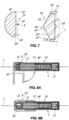
- the cam element 21 will continue to rotate around the axis X for a further third angular section, which may for example be of about 30°. Such movement will bring the cam element 21, along with the door-leaf A, from the second intermediate working position ( FIG. 3C ) to the final position ( FIG. 4C ).
- the end portion 23" of the cam element 21 may exclusively rest against the central portion 33 of the cam follower element 32', and more in particular against the section 35" thereof.
- the length of the latter i.e. substantially the distance d3 between the ends 37' and 37′′′ , may define the third angular section of the rotation of the door-leaf A.
- the closing rotation of the door-leaf A may occur at a substantially constant speed.
- the cam element 21 may have a predetermined distance d5 from the axis X.
- the central portion 33 in the final portion ( FIG. 4C ) will act against the cam element 21 to force the closing door-leaf A against the frame S.
- Such configuration may be particularly useful to promote the mutual interaction between the cam element 21 and the cam follower element 32' substantially for the entire opening and/or closing rotation of the door-leaf A.
- the damping means that supply the resistance strength to the weight force A during the rotation are of the hydraulic type.
- the damping means that supply the resistance strength to the weight force of the door-leaf A during the rotation may be of the mechanical type.
- such mechanical damping means may include or consist of a compression spring 40'.
- Such spring may have characteristics such to supply the aforementioned resistance strength. More in particular, the compression spring 40' may have a high rigidity, for example of at least 10 Kgf / mm.
- the expression rigidity of a compression spring is used to indicate the force required to compress the length unit, for example expressed in kilogram-force per compression millimetre of the spring.
- the slider 11 may be defined by a solid cylinder which includes the cam follower element 32'.
- the spring 40' may be interposed between the slider 11 and the hinge body 10. More in particular, the spring 40' may be interposed between the slider 11 and the bottom cap 17 of the latter.
- the working chamber 11' may be without the rod 16.
- All the other characteristics of the embodiment of the hinge 1 of FIGS. 8A and 8B may be identical to those of the embodiment of the hinge 1 of FIGS. 1A to 4C .
- the configuration of the cam element 21 and that of the cam follower element 32' may be identical.
- the operation may also be substantially be the same one described above, except for the fact that the resistance strength is given by the progressive compression of the spring 40'.
Landscapes
- Closing And Opening Devices For Wings, And Checks For Wings (AREA)
- Wing Frames And Configurations (AREA)
Claims (15)
- Scharnier zur Schließsteuerung eines geneigten Schließelements (A), welches ein einer stationären Aufnahmestruktur (S) wie einer Wand, einem Rahmen oder einem Boden befestigt ist, insbesondere für geneigte Türen oder Türblätter (A), wobei das Scharnier die Steuerung des geneigten Schließelements (A) über die gesamte Winkeldrehung von der geöffneten Stellung in die geschlossene Stellung ermöglicht, wobei das Scharnier folgendes umfasst:- einen Scharnierkörper (10), der an einem von dem geneigten Schließelement (A) oder der stationären Aufnahmestruktur (S) verankert werden kann, wobei der Scharnierkörper (10) in seinem Inneren wenigstens eine Arbeitskammer (11') umfasst, die wenigstens eine erste Längsachse (Y) definiert;- einen Stift (20), der eine zweite Längsachse (X) definiert, die an dem jeweils anderen von dem geneigten Schließelement (A) und der stationären Aufnahmestruktur (S) befestigbar ist, wobei der Stift (20) und der Scharnierkörper (10) miteinander so verbunden sind, dass sie relativ zueinander um die zweite Achse (X) oder um eine sich dazu parallel erstreckende Achse drehbar sind;- wenigstens ein Schieberelement (11), welches in die wenigstens eine Arbeitskammer (11') eingesetzt ist;wobei der Stift (20) ein Nockenelement (21) umfasst, welches mit diesem integral drehbar ist, wobei das Schieberelement (11) ein Mitnehmerelement (32') umfasst, das mit dem Nockenelement (21) so zusammenwirkt, dass während des Schließens des geneigten Schließelements (A) eine gegenseitige Drehung zwischen dem Stift (20) und dem Scharnierkörper (10) um die zweite Achse (X) dem Gleiten des Schieberelements (11) um die erste Achse (Y) entspricht, wobei Dämpfungsmittel für das gegenseitige Zusammenwirken mit dem Schieberelement (11) während dessen Verlagerung vorgesehen sind,wobei das Mitnehmerelement (32') wenigstens einen ersten Wirkteil (33) mit einem ersten Endbereich (37') aufweist, der proximal zu der zweiten Achse (X) angeordnet ist und weiterhin einen zweiten gegenüberliegenden Endbereich (37") aufweist, der distal dazu angeordnet ist, wobei das Nockenelement (21) wenigstens einen zweiten Wirkteil (22) und wenigstens einen dritten Wirkteil (23") aufweist;und wobei das Nockenelement (21) und das Mitnehmerelement (32) gegenseitig so ausgebildet sind, dass während der gegenseitigen Schließdrehung zwischen dem Stift (20) und dem Scharnierkörper (10) um die zweite Achse (X):- über einen ersten Winkelbereich der wenigstens eine zweite Wirkteil (22) sich auf dem ersten Endbereich (37') aus einer anfänglichen Arbeitsstellung in eine erste Zwischen-Arbeitsstellung dreht, wobei der wenigstens eine dritte Wirkteil (23") in Eingriff mit dem zweiten Endbereich (37") gelangt, sodass das Schieberelement (11) im Wesentlichen stationär bleibt und so, dass die Drehung des geneigten Schließelements (A) im Wesentlichen nicht gebremst wird;- über einen zweiten Winkelbereich das Nockenelement (21) sich um die zweite Achse (X) dreht, wobei der wenigstens eine dritte Wirkteil (23") ausschließlich in Eingriff mit dem wenigstens einen ersten Wirkteil (33) ist, um aus der ersten Zwischen-Arbeitsstellung in eine End-Arbeitsstellung verlagert zu werden, wobei der wenigstens eine dritte Wirkteil (23") in der Nähe oder in Eingriff mit dem ersten Endbereich (37') ist, um das Verschieben des Schieberelements (11) entlang der ersten Achse (Y) und das darauffolgende Dämpfen der Drehung des geneigten Schließelements (A) mit einem vorbestimmten Widerstand zu bewirken.
- Scharnier nach Anspruch 1, bei welchem die ersten und zweiten Endbereiche (37', 37") einen ersten Abstand (d1) voneinander entlang der ersten Achse (Y) aufweisen, welcher den ersten Winkelbereich definiert.
- Scharnier nach einem der Ansprüche 1 oder 2, bei welchem die ersten und zweiten Endbereiche (37', 37") einen zweiten Abstand (d2) aufweisen, der den zweiten Winkelbereich der Drehung des Nockenelements (21) umfasst.
- Scharnier nach einem der Ansprüche 1, 2 oder 3, bei welchem der wenigstens eine Wirkteil (33) wenigstens einen ersten Abschnitt (35', 35") aufweist, der bezüglich der ersten Achse (Y) im Wesentlichen geneigt ist, wobei der wenigstens eine erste Abschnitt (35', 35") zwischen den ersten und zweiten Endbereichen (37', 37") angeordnet ist, wobei der wenigstens eine erste Abschnitt (35', 35") vorzugsweise flach oder leicht gekrümmt ausgebildet ist.
- Scharnier nach einem der vorhergehenden Ansprüche, bei welchem das Nockenelement (21) im Wesentlichen flach oder leicht gekrümmt ausgebildet ist, das flache oder leicht gekrümmte Nockenelement (21) sich in der Ausgangsstellung im Wesentlichen senkrecht zu der ersten Achse (Y) erstreckt und sich in der Endstellung im Wesentlichen parallel zu der ersten Achse (Y) erstreckt.
- Scharnier nach Anspruch 5, bei welchem der wenigstens eine Wirkteil (33) wenigstens einen zweiten Abschnitt (36) aufweist, der dem wenigstens einen ersten Abschnitt (35', 35") benachbart ist, der den ersten Endbereich (37') umfasst oder definiert, der zweite Abschnitt (36) bezüglich des Nockenelements (21) eine Gegenkontur ausbildet, um mit diesem so zusammenzuwirken, dass das Scharnier in der geschlossenen und/oder geöffneten Stellung in der Ausgangsstellung gehalten wird.
- Scharnier nach einem der vorhergehenden Ansprüche, bei welchem der wenigstens eine erste Wirkteil (33) wenigstens einen dritten Abschnitt (34', 34") aufweist, der an den wenigstens einen ersten Abschnitt (35', 35") angrenzt, welches den zweiten Endbereich (37") umfasst oder definiert, wobei dass wenigstens eine dritte Wirkteil (23") innerhalb des zweiten Winkelbereichs in Eingriff mit dem dritten Abschnitt (34', 34") gelangt und anschließend in Eingriff mit dem ersten Abschnitt (35', 35") des Mitnehmerelements (32') gelangt wobei der wenigstens eine dritte Abschnitt (34', 34") vorzugsweise im Wesentlichen bezüglich des wenigstens einen ersten Abschnitts (35', 35") geneigt ist, sodass der erste Widerstand aufgrund des Zusammenwirkens zwischen dem wenigstens einen dritten Wirkteil (23') und dem dritten Abschnitt (34', 34") unterschiedlich ist zu dem zweiten Widerstand aufgrund des Zusammenwirkens zwischen dem wenigstens einen dritten Wirkteil (23') und dem ersten Abschnitt (35', 35"), wobei der zweite Widerstand vorzugsweise größer als der erste Widerstand ist.
- Scharnier nach dem vorhergehenden Anspruch, bei welchem der wenigstens eine dritte Abschnitt (34', 34") des Mitnehmerelements (32') sich vorzugsweise im Wesentlichen senkrecht zu der ersten Achse (Y) erstreckt.
- Scharnier nach einem der Ansprüche 7 oder 8, bei welchem der wenigstens eine erste Wirkteil (33) einen dritten Endbereich (37") aufweist, der zwischen dem wenigstens einen dritten Abschnitt (34', 34") und dem wenigstens einen ersten Abschnitt (35', 35") angeordnet ist, wobei die zweiten und dritten Endbereiche (37", 37‴) einen dritten Abstand (d3) voneinander aufweisen, der den Teil des zweiten Winkelbereichs definiert, in welchem die Drehung des Schließelements (A) hydraulisch mittels des ersten Widerstands gedämpft wird und die ersten und dritten Endbereiche (37', 37") einen vierten Abstand (d4) voneinander haben, der einen Teil des zweiten Winkelbereichs definiert, wobei die Drehung des geneigten Schließelements (A) mit dem zweiten Widerstand gedämpft wird.
- Scharnier nach einem oder mehreren der vorhergehenden Ansprüche, bei welchem das Nockenelement (21) und das Mitnehmerelement (32) gegenseitig so konfiguriert sind, dass während der gegenseitigen Öffnungs- und/oder Schließdrehung die Geschwindigkeit des geneigten Schließelements (A) im Wesentlichen konstant ist.
- Scharnier nach einem der vorhergehenden Ansprüche, bei welchem das Nockenelement (21) einen fünften vorbestimmten Abstand (d5) von der zweiten Achse (X) aufweist, derart, um mit dem Mitnehmerelement (32') im Wesentlichen über die gesamte Schließdrehung des geneigten Schließelements (A) zusammenzuwirken.
- Scharnier nach einem der vorhergehenden Ansprüche, weiterhin umfassend elastische Rückholmittel (40), welche auf das Schiebeelement (11) wirken, um dies nach der gegenseitigen Schließdrehung in die Ausgangsposition zurückzustellen.
- Scharnier nach einem der vorhergehenden Ansprüche, bei welchem die Dämpfungsmittel mechanischer Art sind und wenigstens eine Druckfeder (40') umfassen, Letztere vorzugsweise mit einer Steifigkeit von wenigstens 10 Kgf/mm.
- Scharnier nach einem der Ansprüche 1 bis 12, bei welchem die Dämpfungsmittel hydraulischer Art sind und folgendes umfassen:- ein hydraulisches Dämpfungsfluid, vorzugsweise Öl;- einen hydraulischen Kreislauf (12, 13, 14) in welchem die Hydraulikflüssigkeit zirkuliert;- Steuerungsmittel (50) die in den hydraulischen Kreislauf (12, 13, 14) eingesetzt sind, um die Zirkulation der hydraulischen Dämpfungsflüssigkeit während der Verlagerung des Schieberelements (11) zu steuern;um die gegenseitige Schließdrehung des Stifts (20) und des Scharnierkörpers (10) hydraulisch zu dämpfen.
- Schließsystem umfassend:- eine ortsfeste Aufnahmestruktur (S), wie beispielsweise eine Wand, einen Rahmen oder einen Boden;- wenigstens ein geneigtes Schließelement (A), das drehbar an der ortsfesten Aufnahmestruktur (S) befestigt ist, um sich um eine Drehachse (X) zu drehen, wobei die ortsfeste Aufnahmestruktur (S) so ausgebildet ist, dass die Drehachse (X) bezüglich einer vertikalen Achse geneigt ist;- wenigstens ein Scharnier (1), das zwischen der ortsfesten Aufnahmestruktur (S) und dem wenigstens einen geneigten Schließelement (A) angeordnet ist, wobei das wenigstens eine Scharnier (1) das gesteuerte Scharnier nach einem oder mehrerer der vorhergehenden Ansprüche ist.
Applications Claiming Priority (1)
| Application Number | Priority Date | Filing Date | Title |
|---|---|---|---|
| IT102018000004608A IT201800004608A1 (it) | 2018-04-17 | 2018-04-17 | Cerniera di controllo per porte o ante inclinate |
Publications (3)
| Publication Number | Publication Date |
|---|---|
| EP3556980A1 EP3556980A1 (de) | 2019-10-23 |
| EP3556980B1 true EP3556980B1 (de) | 2025-06-25 |
| EP3556980C0 EP3556980C0 (de) | 2025-06-25 |
Family
ID=62875204
Family Applications (1)
| Application Number | Title | Priority Date | Filing Date |
|---|---|---|---|
| EP19169402.5A Active EP3556980B1 (de) | 2018-04-17 | 2019-04-16 | Scharnier zur kontrolle von geneigten türen oder türblättern |
Country Status (2)
| Country | Link |
|---|---|
| EP (1) | EP3556980B1 (de) |
| IT (1) | IT201800004608A1 (de) |
Families Citing this family (1)
| Publication number | Priority date | Publication date | Assignee | Title |
|---|---|---|---|---|
| US11261637B2 (en) * | 2016-12-15 | 2022-03-01 | In & Tec S.R.L. | Hinge for the rotatable movement of a door, a shutter or the like |
Family Cites Families (3)
| Publication number | Priority date | Publication date | Assignee | Title |
|---|---|---|---|---|
| DE202007017736U1 (de) * | 2007-12-17 | 2009-04-30 | Altura Leiden Holding B.V. | Trennwand |
| CN102454326B (zh) * | 2010-10-14 | 2016-03-30 | 邹忠 | 带有自动定心组件的铰链 |
| GB2525444A (en) * | 2014-04-25 | 2015-10-28 | Bestko Prec Ltd | Damped Hinge |
-
2018
- 2018-04-17 IT IT102018000004608A patent/IT201800004608A1/it unknown
-
2019
- 2019-04-16 EP EP19169402.5A patent/EP3556980B1/de active Active
Also Published As
| Publication number | Publication date |
|---|---|
| EP3556980A1 (de) | 2019-10-23 |
| EP3556980C0 (de) | 2025-06-25 |
| IT201800004608A1 (it) | 2019-10-17 |
Similar Documents
| Publication | Publication Date | Title |
|---|---|---|
| JP6813504B2 (ja) | 家具のリーフ用の引き上げシステム | |
| EP2426300B1 (de) | Scharnier zum Schließen von Türen, insbesondere für Glastüren | |
| RU2500870C2 (ru) | Предмет мебели с выталкивающим устройством для подвижных деталей мебели | |
| EP3309336B1 (de) | Schnappscharnier mit gedämpftem verschliessen | |
| KR100835730B1 (ko) | 볼타입 클러치장치 및 이를 이용한 자동복귀 힌지장치 | |
| EP3887632B1 (de) | Möbelscharnier für nach oben öffnende schranktüren | |
| ITVI20110124A1 (it) | Dispositivo a pistone per la chiusura automatica controllatadi porte, ante o similari | |
| EP1501992A1 (de) | Mehrgelenkscharnier | |
| EP3298224B1 (de) | Scharnier mit geringer sperrigkeit | |
| CN1715605B (zh) | 用于翼式和旋转翼式打开的窗和门的隐式铰接装置 | |
| JP2020502404A5 (de) | ||
| EP3556980B1 (de) | Scharnier zur kontrolle von geneigten türen oder türblättern | |
| EP3555399B1 (de) | Scharnier zur drehbewegung einer tür, eines verschlusses oder dergleichen | |
| EP4479616A1 (de) | Scharnier für türen oder klappläden, insbesondere für kühlschränke, sowie system mit diesem scharnier | |
| EP3371406B1 (de) | Scharnier zur drehbewegung einer tür, eines verschlusses oder dergleichen | |
| EP3475509B1 (de) | Scharniermechanismus und scharniersystem | |
| KR101784984B1 (ko) | 개폐속도조절 및 자동이송이 가능한 폴딩도어 | |
| TWI911564B (zh) | 阻尼鉸鍊及具阻尼鉸鏈之功能實體 | |
| EP4636209A2 (de) | Antriebsvorrichtung für klappbare türen von kleiderschränken, begehbaren schränken oder möbelstücken im allgemeinen | |
| IT202200000212A1 (it) | Cerniera perfezionata in particolare per un elettrodomestico | |
| IT201900006586A1 (it) | Cerniera per la movimentazione girevole di una porta, un’anta o similare | |
| EP4536927A1 (de) | Hebesystem für möbeltüren sowie stütz- und hubanordnung für möbeltüren mit dem hebesystem | |
| ITBO940148U1 (it) | Cancello a battente oscillante | |
| IT201900010818A1 (it) | Cerniera a ingombri ridotti | |
| IT201900010821A1 (it) | Cerniera a ingombri ridotti |
Legal Events
| Date | Code | Title | Description |
|---|---|---|---|
| PUAI | Public reference made under article 153(3) epc to a published international application that has entered the european phase |
Free format text: ORIGINAL CODE: 0009012 |
|
| STAA | Information on the status of an ep patent application or granted ep patent |
Free format text: STATUS: THE APPLICATION HAS BEEN PUBLISHED |
|
| AK | Designated contracting states |
Kind code of ref document: A1 Designated state(s): AL AT BE BG CH CY CZ DE DK EE ES FI FR GB GR HR HU IE IS IT LI LT LU LV MC MK MT NL NO PL PT RO RS SE SI SK SM TR |
|
| AX | Request for extension of the european patent |
Extension state: BA ME |
|
| STAA | Information on the status of an ep patent application or granted ep patent |
Free format text: STATUS: REQUEST FOR EXAMINATION WAS MADE |
|
| 17P | Request for examination filed |
Effective date: 20200423 |
|
| RBV | Designated contracting states (corrected) |
Designated state(s): AL AT BE BG CH CY CZ DE DK EE ES FI FR GB GR HR HU IE IS IT LI LT LU LV MC MK MT NL NO PL PT RO RS SE SI SK SM TR |
|
| STAA | Information on the status of an ep patent application or granted ep patent |
Free format text: STATUS: EXAMINATION IS IN PROGRESS |
|
| 17Q | First examination report despatched |
Effective date: 20231026 |
|
| GRAP | Despatch of communication of intention to grant a patent |
Free format text: ORIGINAL CODE: EPIDOSNIGR1 |
|
| STAA | Information on the status of an ep patent application or granted ep patent |
Free format text: STATUS: GRANT OF PATENT IS INTENDED |
|
| INTG | Intention to grant announced |
Effective date: 20250314 |
|
| GRAS | Grant fee paid |
Free format text: ORIGINAL CODE: EPIDOSNIGR3 |
|
| GRAA | (expected) grant |
Free format text: ORIGINAL CODE: 0009210 |
|
| STAA | Information on the status of an ep patent application or granted ep patent |
Free format text: STATUS: THE PATENT HAS BEEN GRANTED |
|
| AK | Designated contracting states |
Kind code of ref document: B1 Designated state(s): AL AT BE BG CH CY CZ DE DK EE ES FI FR GB GR HR HU IE IS IT LI LT LU LV MC MK MT NL NO PL PT RO RS SE SI SK SM TR |
|
| REG | Reference to a national code |
Ref country code: GB Ref legal event code: FG4D |
|
| REG | Reference to a national code |
Ref country code: CH Ref legal event code: EP |
|
| REG | Reference to a national code |
Ref country code: CH Ref legal event code: EP |
|
| REG | Reference to a national code |
Ref country code: IE Ref legal event code: FG4D |
|
| REG | Reference to a national code |
Ref country code: DE Ref legal event code: R096 Ref document number: 602019071452 Country of ref document: DE |
|
| U01 | Request for unitary effect filed |
Effective date: 20250723 |
|
| U07 | Unitary effect registered |
Designated state(s): AT BE BG DE DK EE FI FR IT LT LU LV MT NL PT RO SE SI Effective date: 20250729 |
|
| PG25 | Lapsed in a contracting state [announced via postgrant information from national office to epo] |
Ref country code: GR Free format text: LAPSE BECAUSE OF FAILURE TO SUBMIT A TRANSLATION OF THE DESCRIPTION OR TO PAY THE FEE WITHIN THE PRESCRIBED TIME-LIMIT Effective date: 20250926 Ref country code: NO Free format text: LAPSE BECAUSE OF FAILURE TO SUBMIT A TRANSLATION OF THE DESCRIPTION OR TO PAY THE FEE WITHIN THE PRESCRIBED TIME-LIMIT Effective date: 20250925 |
|
| PG25 | Lapsed in a contracting state [announced via postgrant information from national office to epo] |
Ref country code: HR Free format text: LAPSE BECAUSE OF FAILURE TO SUBMIT A TRANSLATION OF THE DESCRIPTION OR TO PAY THE FEE WITHIN THE PRESCRIBED TIME-LIMIT Effective date: 20250625 |
|
| PG25 | Lapsed in a contracting state [announced via postgrant information from national office to epo] |
Ref country code: RS Free format text: LAPSE BECAUSE OF FAILURE TO SUBMIT A TRANSLATION OF THE DESCRIPTION OR TO PAY THE FEE WITHIN THE PRESCRIBED TIME-LIMIT Effective date: 20250925 |
|
| PG25 | Lapsed in a contracting state [announced via postgrant information from national office to epo] |
Ref country code: IS Free format text: LAPSE BECAUSE OF FAILURE TO SUBMIT A TRANSLATION OF THE DESCRIPTION OR TO PAY THE FEE WITHIN THE PRESCRIBED TIME-LIMIT Effective date: 20251025 |
|
| PG25 | Lapsed in a contracting state [announced via postgrant information from national office to epo] |
Ref country code: SM Free format text: LAPSE BECAUSE OF FAILURE TO SUBMIT A TRANSLATION OF THE DESCRIPTION OR TO PAY THE FEE WITHIN THE PRESCRIBED TIME-LIMIT Effective date: 20250625 |
|
| PG25 | Lapsed in a contracting state [announced via postgrant information from national office to epo] |
Ref country code: CZ Free format text: LAPSE BECAUSE OF FAILURE TO SUBMIT A TRANSLATION OF THE DESCRIPTION OR TO PAY THE FEE WITHIN THE PRESCRIBED TIME-LIMIT Effective date: 20250625 |
|
| PG25 | Lapsed in a contracting state [announced via postgrant information from national office to epo] |
Ref country code: PL Free format text: LAPSE BECAUSE OF FAILURE TO SUBMIT A TRANSLATION OF THE DESCRIPTION OR TO PAY THE FEE WITHIN THE PRESCRIBED TIME-LIMIT Effective date: 20250625 |
|
| PG25 | Lapsed in a contracting state [announced via postgrant information from national office to epo] |
Ref country code: SK Free format text: LAPSE BECAUSE OF FAILURE TO SUBMIT A TRANSLATION OF THE DESCRIPTION OR TO PAY THE FEE WITHIN THE PRESCRIBED TIME-LIMIT Effective date: 20250625 |
|
| PG25 | Lapsed in a contracting state [announced via postgrant information from national office to epo] |
Ref country code: ES Free format text: LAPSE BECAUSE OF FAILURE TO SUBMIT A TRANSLATION OF THE DESCRIPTION OR TO PAY THE FEE WITHIN THE PRESCRIBED TIME-LIMIT Effective date: 20250625 |