EP3556980B1 - Charniere pour la commande de portes ou de feuilles de porte inclinées - Google Patents
Charniere pour la commande de portes ou de feuilles de porte inclinées Download PDFInfo
- Publication number
- EP3556980B1 EP3556980B1 EP19169402.5A EP19169402A EP3556980B1 EP 3556980 B1 EP3556980 B1 EP 3556980B1 EP 19169402 A EP19169402 A EP 19169402A EP 3556980 B1 EP3556980 B1 EP 3556980B1
- Authority
- EP
- European Patent Office
- Prior art keywords
- section
- hinge
- axis
- rotation
- closing
- Prior art date
- Legal status (The legal status is an assumption and is not a legal conclusion. Google has not performed a legal analysis and makes no representation as to the accuracy of the status listed.)
- Active
Links
Images


Classifications
-
- E—FIXED CONSTRUCTIONS
- E05—LOCKS; KEYS; WINDOW OR DOOR FITTINGS; SAFES
- E05F—DEVICES FOR MOVING WINGS INTO OPEN OR CLOSED POSITION; CHECKS FOR WINGS; WING FITTINGS NOT OTHERWISE PROVIDED FOR, CONCERNED WITH THE FUNCTIONING OF THE WING
- E05F1/00—Closers or openers for wings, not otherwise provided for in this subclass
- E05F1/08—Closers or openers for wings, not otherwise provided for in this subclass spring-actuated, e.g. for horizontally sliding wings
- E05F1/10—Closers or openers for wings, not otherwise provided for in this subclass spring-actuated, e.g. for horizontally sliding wings for swinging wings, e.g. counterbalance
- E05F1/12—Mechanisms in the shape of hinges or pivots, operated by springs
- E05F1/1246—Mechanisms in the shape of hinges or pivots, operated by springs with a coil spring perpendicular to the pivot axis
- E05F1/1253—Mechanisms in the shape of hinges or pivots, operated by springs with a coil spring perpendicular to the pivot axis with a compression spring
- E05F1/1261—Mechanisms in the shape of hinges or pivots, operated by springs with a coil spring perpendicular to the pivot axis with a compression spring for counterbalancing
-
- E—FIXED CONSTRUCTIONS
- E05—LOCKS; KEYS; WINDOW OR DOOR FITTINGS; SAFES
- E05F—DEVICES FOR MOVING WINGS INTO OPEN OR CLOSED POSITION; CHECKS FOR WINGS; WING FITTINGS NOT OTHERWISE PROVIDED FOR, CONCERNED WITH THE FUNCTIONING OF THE WING
- E05F1/00—Closers or openers for wings, not otherwise provided for in this subclass
- E05F1/02—Closers or openers for wings, not otherwise provided for in this subclass gravity-actuated, e.g. by use of counterweights
- E05F1/04—Closers or openers for wings, not otherwise provided for in this subclass gravity-actuated, e.g. by use of counterweights for wings which lift during movement, operated by their own weight
- E05F1/06—Mechanisms in the shape of hinges or pivots, operated by the weight of the wing
- E05F1/068—Mechanisms in the shape of hinges or pivots, operated by the weight of the wing with inclined pivot-axes
-
- E—FIXED CONSTRUCTIONS
- E05—LOCKS; KEYS; WINDOW OR DOOR FITTINGS; SAFES
- E05F—DEVICES FOR MOVING WINGS INTO OPEN OR CLOSED POSITION; CHECKS FOR WINGS; WING FITTINGS NOT OTHERWISE PROVIDED FOR, CONCERNED WITH THE FUNCTIONING OF THE WING
- E05F3/00—Closers or openers with braking devices, e.g. checks; Construction of pneumatic or liquid braking devices
- E05F3/20—Closers or openers with braking devices, e.g. checks; Construction of pneumatic or liquid braking devices in hinges
-
- E—FIXED CONSTRUCTIONS
- E05—LOCKS; KEYS; WINDOW OR DOOR FITTINGS; SAFES
- E05Y—INDEXING SCHEME ASSOCIATED WITH SUBCLASSES E05D AND E05F, RELATING TO CONSTRUCTION ELEMENTS, ELECTRIC CONTROL, POWER SUPPLY, POWER SIGNAL OR TRANSMISSION, USER INTERFACES, MOUNTING OR COUPLING, DETAILS, ACCESSORIES, AUXILIARY OPERATIONS NOT OTHERWISE PROVIDED FOR, APPLICATION THEREOF
- E05Y2201/00—Constructional elements; Accessories therefor
- E05Y2201/60—Suspension or transmission members; Accessories therefor
- E05Y2201/622—Suspension or transmission members elements
- E05Y2201/638—Cams; Ramps
-
- E—FIXED CONSTRUCTIONS
- E05—LOCKS; KEYS; WINDOW OR DOOR FITTINGS; SAFES
- E05Y—INDEXING SCHEME ASSOCIATED WITH SUBCLASSES E05D AND E05F, RELATING TO CONSTRUCTION ELEMENTS, ELECTRIC CONTROL, POWER SUPPLY, POWER SIGNAL OR TRANSMISSION, USER INTERFACES, MOUNTING OR COUPLING, DETAILS, ACCESSORIES, AUXILIARY OPERATIONS NOT OTHERWISE PROVIDED FOR, APPLICATION THEREOF
- E05Y2900/00—Application of doors, windows, wings or fittings thereof
- E05Y2900/30—Application of doors, windows, wings or fittings thereof for domestic appliances
- E05Y2900/31—Application of doors, windows, wings or fittings thereof for domestic appliances for refrigerators
Definitions
- the present invention generally regards the technical field of hinges, and it particularly regards a control hinge, in particular for doors, door-leaves and the like of the inclined type.
- the glass door-leaves of refrigerators for the large-scale distribution, such as supermarkets or hypermarkets are relatively heavy, about 20 - 25 kg.
- the door-leaf is particularly heavy to open.
- An object of the present invention is to overcome the aforementioned drawbacks, by providing a control hinge for inclined doors that is highly efficient and relatively economic.
- Another object of the invention is to provide a hinge that allows to control the inclined door-leaf for the entire angular rotation from the opening position to the closing position.
- Another object of the invention is to provide a hinge that allows to have a substantially constant closing speed of the inclined door-leaf for the entire angular rotation from the opening position to the closing position.
- Another object of the invention is to provide a hinge that allows an easy opening of the inclined door-leaf.
- the hinge according to the invention can advantageously be used with closing elements A mounted inclined on a support structure S.
- the hinge 1 may be applied to cold stores with inclined doors, or it can be integrated in the tubular frame thereof.
- the hinge 1 may be applied to glass door-leaves, such as those of a display window or display case.
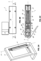
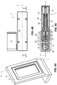
- the hinge 1 is suitable for rotatably coupling a stationary support structure, for example a tubular frame S, and a closing element, for example a door-leaf A, rotatably movable between an opening position, illustrated for example in FIG. 1A , and a closing position, illustrated for example in FIG. 4A , around a rotation axis X.
- a stationary support structure for example a tubular frame S
- a closing element for example a door-leaf A
- the hinge 1 may be a control or hydraulic brake hinge for hydraulically damping the closing displacement of the door-leaf A.
- the hinge 1 includes a hinge body 10, may be substantially sheet-like defining a plane, and a pin 20 defining the rotation axis X.
- closing element A and the stationary support structure S may also rotate around an axis parallel to the axis X without departing from the scope of protection of the attached claims.
- the hinge body 10 may be anchored to the frame S and the pin 20 to the door-leaf A.
- the pin 20 may be movable, while the hinge body 10 may be fixed.
- the pin 20 may be fixed and the hinge body 10 may be movable without departing from the scope of protection of the attached claims.
- the hinge body 10 and the pin 20 are mutually coupled to rotate around the axis X between the door-leaf open A, illustrated for example in FIG. 1A , and the door-leaf closed position A, illustrated for example in FIG. 4A .
- the hinge 1 may open in both directions of rotation of the pin 20.
- the hinge may also open in a single direction of rotation without departing from the scope of protection of the attached claims.
- the pin 20 includes a cam element 21 integrally joined thereto interacting with a slider 11 slidable along an axis Y defined by the working chamber 11' inside the hinge body 10.
- Such axis Y may be substantially perpendicular to the axis X. It is clear that the axes X and Y may also be parallel without departing from the scope of protection of the attached claims.
- Such retracted and extended end-stop positions may suitably vary, and not necessarily corresponding to the maximum distal and/or proximal position that can be taken by the slider 11.
- a hydraulic chamber 11" filed with oil or other hydraulic damping fluid may be provided for inside the slider 11.
- the cylinder 60 may divide the hydraulic chamber 11" into a first and a second variable volume compartment 12, 13, placed in fluid communication with each other and preferably adjacent.
- the working fluid may circulate in a hydraulic circuit inside the hydraulic chamber 11", and more in particular it may flow from one to the other of the compartments 12, 13 through a calibrated passage obtained by interference between the hole 14 and valve pin 15.
- Valve means 50 for controlling the through-flow of the working fluid between the two compartments 12, 13 may be present.
- the hydraulic chamber 11' and the relative components therein may define hydraulic damping means, as better outlined hereinafter.
- elastic means 40 mutually interacting with the slider 11 may be provided for inside the hinge body 10.
- the elastic counteracting means may include, respectively may consist of, a spiral spring 40 with predetermined diameter.
- the elastic means 40 may be recovery means, i.e. having a force such to return the slider 11 from the proximal position to the distal position but not closing or opening the door-leaf A.
- recovery elastic means 40 may advantageously be configured and/or dimensioned so as to push the door-leaf A towards the open or closed position, so as to facilitate the user opening or closing the door-leaf A manually.
- the spiral spring 40 may be fitted onto the rod 16, which may possibly serve as a guide for the same.
- the spring 40 will remain interposed between the bottom cap 17 of the hinge body 10 and the rear face 51 of the slider 31, which will act as an abutment face for the spring 40.
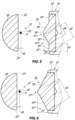
- the slider 11 includes a cam follower element 32' with possibly an operative face 32 and thus interacting with the cam element 21 so that the rotation of the latter around the axis X promotes the sliding of the slider along the axis Y .
- the cam element 21 may be substantially flat. More in particular, in the initial position for example illustrated in FIG. 1C the substantially flat cam element 21 may be substantially perpendicular to the axis Y , while in the final position illustrated for example in FIG. 4C it may be substantially parallel to the axis Y .
- the operative face 32 may have a suitable shape, which will allow to control the closing of the door-leaf A from the full opening position illustrated for example in FIG. 1A to the closing position illustrated for example in FIG. 4A .
- the door-leaf A may close at a substantially constant speed, thus that is without banging against the frame S.
- the presence of the spring 40 dimensioned as mentioned above will facilitate the opening of the door-leaf A by the user.
- the apparent weight of the opening door-leaf A will be lesser than the actual weight, i.e. the weight that the user would be required to overcome without the spring.
- the operative face 32 has an operative portion 33 with possibly at least one first section 35' and 35".
- the latter may be equal to each other.
- the configuration of the operative face 32 may be symmetrical with respect to the axis Y , so that the hinge 1 behaves in the same way in both directions of rotation of the pin 20.
- the operative face 32 may include a single section 35' or 35" without departing from the scope of protection of the attached claims.
- the sections 35', 35" may be substantially flat and preferably inclined with respect to the axis Y . More in particular, the inclination may be divergent with respect to the axis Y in the direction of the bottom cap 17.
- the operative portion 33 may include a second section 36 interposed between the first sections 35', 35".
- the section 36 may be substantially flat. Thus, it may cooperate with the substantially flat cam element 21 in the initial position so as to keep the hinge in the closed position, for example as illustrated in FIG. 1A .
- the portion 33 which will not necessarily be in a central position with respect to the cam follower element but for example in a peripheral position, may include only one inclined section and a top section.
- first sections and the second section may not be necessarily flat, but slightly curved for example.
- the flat or curved top section could also be absent, and it could reduce at a point.
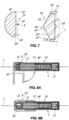
- the cam element 21 will rotate around the axis X for a first angular section to pass from the initial position ( FIG. 1C ) to an intermediate working position ( FIG. 2C ) in which the central portion 22 thereof tilts in the central portion 33 of the operative face 32.
- the cam element 21 will continue to rotate around the axis X for a further second angular section, which may for example be of about 40°. Such movement will bring the cam element 21, along with the door-leaf A, from the first intermediate working position ( FIG. 2C ) to a second intermediate working position ( FIG. 3C ).
- the end portion 23" of the cam element 21 may exclusively rest against the lateral portion 34" of the cam element 32', up to impacting against the central portion 33.
- the second rotation step of the cam element 21 will displace the slider 11 along the axis Y , promoting the through-flow of the working fluid from compartment 12 to compartment 13 through the calibrated passage defined between the hole 14 and the valve pin 15.
- the movement of the door-leaf A around the axis X will be hydraulically damped with a first predetermined resistance strength.
- the length of the lateral portion 34" of the cam element 32' against which the end portion 23" of the cam element 21 rests, i.e. substantially the distance d2 between the ends 37' and 37", may define the second angular section of the rotation of the door-leaf A.
- the cam element 21 will continue to rotate around the axis X for a further third angular section, which may for example be of about 30°. Such movement will bring the cam element 21, along with the door-leaf A, from the second intermediate working position ( FIG. 3C ) to the final position ( FIG. 4C ).
- the end portion 23" of the cam element 21 may exclusively rest against the central portion 33 of the cam follower element 32', and more in particular against the section 35" thereof.
- the length of the latter i.e. substantially the distance d3 between the ends 37' and 37′′′ , may define the third angular section of the rotation of the door-leaf A.
- the closing rotation of the door-leaf A may occur at a substantially constant speed.
- the cam element 21 may have a predetermined distance d5 from the axis X.
- the central portion 33 in the final portion ( FIG. 4C ) will act against the cam element 21 to force the closing door-leaf A against the frame S.
- Such configuration may be particularly useful to promote the mutual interaction between the cam element 21 and the cam follower element 32' substantially for the entire opening and/or closing rotation of the door-leaf A.
- the damping means that supply the resistance strength to the weight force A during the rotation are of the hydraulic type.
- the damping means that supply the resistance strength to the weight force of the door-leaf A during the rotation may be of the mechanical type.
- such mechanical damping means may include or consist of a compression spring 40'.
- Such spring may have characteristics such to supply the aforementioned resistance strength. More in particular, the compression spring 40' may have a high rigidity, for example of at least 10 Kgf / mm.
- the expression rigidity of a compression spring is used to indicate the force required to compress the length unit, for example expressed in kilogram-force per compression millimetre of the spring.
- the slider 11 may be defined by a solid cylinder which includes the cam follower element 32'.
- the spring 40' may be interposed between the slider 11 and the hinge body 10. More in particular, the spring 40' may be interposed between the slider 11 and the bottom cap 17 of the latter.
- the working chamber 11' may be without the rod 16.
- All the other characteristics of the embodiment of the hinge 1 of FIGS. 8A and 8B may be identical to those of the embodiment of the hinge 1 of FIGS. 1A to 4C .
- the configuration of the cam element 21 and that of the cam follower element 32' may be identical.
- the operation may also be substantially be the same one described above, except for the fact that the resistance strength is given by the progressive compression of the spring 40'.
Landscapes
- Closing And Opening Devices For Wings, And Checks For Wings (AREA)
- Wing Frames And Configurations (AREA)
Claims (15)
- Une charnière pour la commande de fermeture d'un élément de fermeture incliné (A) ancrée à une structure de support fixe (S), telle qu'une paroi, un cadre ou un plancher, en particulier pour des portes inclinées ou des battants de porte (A), la charnière permettant de commander l'élément incliné (A) pour toute la rotation angulaire de la position d'ouverture à la position de fermeture, la charnière comprenant :- un corps de charnière (10) adapté pour être ancré à un de l'élément de fermeture incliné (A) et de la structure de support fixe (S), ledit corps de charnière (10) comprenant intérieurement au moins une chambre de travail (11') définissant un premier axe longitudinal (Y) ;- une broche (20) définissant un deuxième axe longitudinal (X) adaptée pour être ancrée à l'autre de l'élément de fermeture incliné (A) et à la structure de support fixe (S), ladite broche (20) et ledit corps de charnière (10) étant couplés mutuellement l'un à l'autre pour tourner relativement l'un par rapport à l'autre autour dudit deuxième axe (X) ou autour d'un axe parallèle à celui-ci ;- au moins un élément coulissant (11) inséré dans ladite au moins une chambre de travail (11') ;dans laquelle ladite broche (20) comprend un élément de came (21) adapté pour tourner solidairement avec celle-ci, ledit élément coulissant (11) comprenant un élément suiveur de came (32') interagissant avec ledit élément de came (21) de sorte que pendant ladite fermeture de l'élément de fermeture incliné (A), une rotation mutuelle entre ladite broche (20) et ledit corps de charnière (10) autour dudit deuxième axe (X) correspond au coulissement dudit élément coulissant (11) le long dudit premier axe (Y), des moyens d'amortissement étant fournis pour interagir mutuellement avec ledit élément coulissant (11) pendant le déplacement de celui-ci ;dans laquelle ledit élément suiveur de came (32') a au moins une première partie fonctionnelle (33) avec une première zone d'extrémité (37') proximale audit deuxième axe (X) et une deuxième zone d'extrémité opposée (37") distale à partir de celui-ci, ledit élément de came (21) ayant au moins une deuxième partie fonctionnelle (22) et au moins une troisième partie fonctionnelle (23") ;et dans laquelle l'élément de came (21) et l'élément suiveur de came (32) sont configurés mutuellement de sorte que pendant ladite rotation de fermeture mutuelle entre ladite broche (20) et ledit corps de charnière (10) autour dudit deuxième axe (X) :- pour une première section angulaire, ladite au moins une deuxième partie fonctionnelle (22) tourne sur ladite première zone d'extrémité (37') d'une position de travail initiale à une première position de travail intermédiaire dans laquelle ladite au moins une troisième partie opérationnelle (23") entre en contact avec ladite deuxième zone d'extrémité (37"), de sorte que ledit élément coulissant (11) reste sensiblement fixe et de sorte que la rotation de l'élément de fermeture incliné (A) est sensiblement non freinée ;- pour une deuxième section angulaire, ledit élément de came (21) tourne autour dudit deuxième axe (X) exclusivement avec ladite au moins une troisième partie fonctionnelle (23") en contact avec ladite au moins une première partie fonctionnelle (33) pour passer de ladite première position de travail intermédiaire à une position de travail finale dans laquelle ladite au moins une troisième partie fonctionnelle (23") est à proximité ou en contact avec ladite première zone d'extrémité (37'), de manière à favoriser le coulissement dudit élément coulissant (11) le long dudit premier axe (Y) et l'amortissement conséquent de la rotation de l'élément de fermeture incliné (A) avec une force de résistance prédéterminée.
- Charnière selon la revendication 1, dans laquelle lesdites première et deuxième zones d'extrémité (37', 37") ont une première distance mutuelle (d1) le long dudit premier axe (Y) définissant ladite première section angulaire.
- Charnière selon la revendication 1 ou 2, dans laquelle lesdites première et deuxième zones d'extrémité (37', 37") ont une deuxième distance (d2) définissant ladite deuxième section angulaire de la rotation dudit élément de came (21).
- Charnière selon la revendication 1, 2 ou 3, dans laquelle ladite au moins une première partie fonctionnelle (33) a au moins une première section (35', 35") sensiblement inclinée par rapport audit premier axe (Y), ladite au moins une première section (35', 35") étant interposée entre lesdites première et deuxième zones d'extrémité (37', 37"), ladite au moins une première section (35', 35") étant de préférence plate ou légèrement courbe.
- Charnière selon l'une quelconque des revendications précédentes, dans laquelle ledit élément de came (21) est sensiblement plat ou légèrement courbe, ledit élément de came plat ou légèrement courbe (21) étant de préférence sensiblement perpendiculaire audit premier axe (Y) dans ladite position initiale et sensiblement parallèle audit premier axe (Y) dans ladite position finale.
- Charnière selon la revendication 5, dans laquelle ladite au moins une première partie fonctionnelle (33) a au moins une deuxième section (36) adjacente à ladite au moins une première section (35', 35") qui comprend ou qui définit ladite première zone d'extrémité (37'), ladite deuxième section (36) étant sensiblement contre-formée par rapport audit élément de came (21) de manière à coopérer avec celui-ci pour maintenir la charnière dans la position fermée et/ou ouverte dans ladite position initiale.
- Charnière selon l'une quelconque des revendications précédentes, dans laquelle ladite au moins une première partie fonctionnelle (33) a au moins une troisième section (34', 34") adjacente à ladite au moins une première section (35', 35") qui comprend ou qui définit ladite deuxième zone d'extrémité (37"), ladite au moins une troisième partie fonctionnelle (23") pendant ladite deuxième section angulaire entrant en contact d'abord avec ladite troisième section (34', 34") et ensuite avec ladite première section (35', 35") dudit élément suiveur de came (32'), ladite au moins une troisième section (34', 34") étant de préférence sensiblement inclinée par rapport à ladite au moins une première section (35', 35") de sorte que la première force de résistance due à l'interaction entre ladite au moins une troisième partie fonctionnelle (23") et ladite troisième section (34', 34") est différente par rapport à la deuxième force de résistance due à l'interaction entre l'au moins une troisième partie fonctionnelle (23") et ladite première section (35', 35"), ladite deuxième force de résistance étant de préférence supérieure à ladite première force de résistance.
- Charnière selon la revendication précédente, dans laquelle ladite au moins une troisième section (34', 34") dudit élément suiveur de came (32') est sensiblement plate, ladite au moins une troisième section (34', 34") étant de préférence sensiblement perpendiculaire audit premier axe (Y).
- Charnière selon la revendication 7 ou 8, dans laquelle ladite au moins une première partie fonctionnelle (33) a une troisième zone d'extrémité (37") interposée entre ladite au moins une troisième section (34', 34") et au moins une première section (35', 35"), lesdites deuxième et troisième zones d'extrémité (37', 37") ayant une troisième distance (d3) définissant la partie de ladite deuxième section angulaire dans laquelle la rotation de l'élément de fermeture (A) est amortie hydrauliquement avec ladite première force de résistance, lesdites première et troisième zones d'extrémité (37', 37") ayant une quatrième distance (d4) définissant la partie de ladite deuxième section angulaire dans laquelle la rotation de l'élément de fermeture incliné (A) est amortie avec ladite deuxième force de résistance.
- Charnière selon une ou plusieurs des revendications précédentes, dans laquelle ledit élément de came (21) et ledit élément suiveur de came (32) sont configurés mutuellement de sorte que pendant ladite rotation d'ouverture et/ou de fermeture mutuelle, la vitesse dudit élément de fermeture incliné (A) est sensiblement constante.
- Charnière selon l'une quelconque des revendications précédentes, dans laquelle ledit élément de came (21) a une cinquième distance prédéterminée (d5) à partir dudit deuxième axe (X), de manière à interagir avec ledit élément suiveur de came (32') sensiblement pour toute la rotation de fermeture dudit élément de fermeture incliné (A).
- Charnière selon l'une quelconque des revendications précédentes, comprenant en outre des moyens élastiques de récupération (40) agissant sur ledit élément coulissant (11) pour le faire revenir à sa position initiale suite à ladite rotation de fermeture mutuelle.
- Charnière selon l'une quelconque des revendications précédentes, dans laquelle lesdits moyens d'amortissement sont de type mécanique et comprennent au moins un ressort de compression (40'), ce dernier ayant de préférence une rigidité d'au moins 10 Kgf/mm.
- Charnière selon l'une quelconque des revendications 1 à 12, dans laquelle lesdits moyens d'amortissement sont du type hydraulique et comprennent :- un fluide d'amortissement hydraulique, de préférence de l'huile ;- un circuit hydraulique (12, 13, 14) dans lequel ledit fluide d'amortissement hydraulique circule ;- des moyens de commande (50) insérés dans ledit circuit hydraulique (12, 13, 14) pour commander la circulation dudit fluide d'amortissement hydraulique pendant le déplacement dudit élément coulissant (11) ;de manière à amortir hydrauliquement la rotation de fermeture mutuelle de ladite broche (20) et dudit corps de charnière (10).
- Un système comprenant :- une structure de support fixe (S), telle que par exemple une paroi, un cadre ou un plancher ;- au moins un élément de fermeture incliné (A) monté de manière à pouvoir tourner sur ladite structure de support fixe (S) pour tourner autour d'un axe de rotation (X), ladite structure de support fixe (S) étant configurée de sorte que ledit axe de rotation (X) est incliné par rapport à un axe vertical ;- au moins une charnière (1) interposée entre ladite structure de support fixe (S) et ledit au moins un élément de fermeture incliné (A), ladite au moins une charnière (1) étant la charnière de commande selon une ou plusieurs des revendications précédentes.
Applications Claiming Priority (1)
| Application Number | Priority Date | Filing Date | Title |
|---|---|---|---|
| IT102018000004608A IT201800004608A1 (it) | 2018-04-17 | 2018-04-17 | Cerniera di controllo per porte o ante inclinate |
Publications (3)
| Publication Number | Publication Date |
|---|---|
| EP3556980A1 EP3556980A1 (fr) | 2019-10-23 |
| EP3556980B1 true EP3556980B1 (fr) | 2025-06-25 |
| EP3556980C0 EP3556980C0 (fr) | 2025-06-25 |
Family
ID=62875204
Family Applications (1)
| Application Number | Title | Priority Date | Filing Date |
|---|---|---|---|
| EP19169402.5A Active EP3556980B1 (fr) | 2018-04-17 | 2019-04-16 | Charniere pour la commande de portes ou de feuilles de porte inclinées |
Country Status (2)
| Country | Link |
|---|---|
| EP (1) | EP3556980B1 (fr) |
| IT (1) | IT201800004608A1 (fr) |
Families Citing this family (1)
| Publication number | Priority date | Publication date | Assignee | Title |
|---|---|---|---|---|
| WO2018109732A2 (fr) * | 2016-12-15 | 2018-06-21 | In & Tec S.R.L. | Charnière pour le mouvement rotatif d'une porte, d'un volet ou similaire |
Family Cites Families (3)
| Publication number | Priority date | Publication date | Assignee | Title |
|---|---|---|---|---|
| DE202007017736U1 (de) * | 2007-12-17 | 2009-04-30 | Altura Leiden Holding B.V. | Trennwand |
| CN202659012U (zh) * | 2010-10-14 | 2013-01-09 | 邹忠 | 带有自动定心组件的铰链及门铰链转轴 |
| GB2525444A (en) * | 2014-04-25 | 2015-10-28 | Bestko Prec Ltd | Damped Hinge |
-
2018
- 2018-04-17 IT IT102018000004608A patent/IT201800004608A1/it unknown
-
2019
- 2019-04-16 EP EP19169402.5A patent/EP3556980B1/fr active Active
Also Published As
| Publication number | Publication date |
|---|---|
| EP3556980A1 (fr) | 2019-10-23 |
| IT201800004608A1 (it) | 2019-10-17 |
| EP3556980C0 (fr) | 2025-06-25 |
Similar Documents
| Publication | Publication Date | Title |
|---|---|---|
| JP6813504B2 (ja) | 家具のリーフ用の引き上げシステム | |
| RU2500870C2 (ru) | Предмет мебели с выталкивающим устройством для подвижных деталей мебели | |
| EP2746508A1 (fr) | Charnière de fermeture de porte, en particulier pour portes en verre | |
| EP2909406B1 (fr) | Charnière à encliquetage à fermeture amortie | |
| KR100835730B1 (ko) | 볼타입 클러치장치 및 이를 이용한 자동복귀 힌지장치 | |
| EP3887632B1 (fr) | Charnière de meuble pour portes d'armoire à ouverture vers le haut | |
| EP1501992A1 (fr) | Charniere a plusieurs articulations | |
| CN1715605B (zh) | 用于翼式和旋转翼式打开的窗和门的隐式铰接装置 | |
| EP3298224B1 (fr) | Charnière à faible encombrement | |
| JP2020502404A5 (fr) | ||
| EP3556980B1 (fr) | Charniere pour la commande de portes ou de feuilles de porte inclinées | |
| EP3555399B1 (fr) | Charnière pour le mouvement rotatif d'une porte, d'un volet ou similaire | |
| EP4479616A1 (fr) | Charnière pour portes ou volets oscillants, en particulier pour armoires réfrigérées, ainsi que système comprenant ladite charnière | |
| EP3371406B1 (fr) | Charnière pour mouvement rotatif d'une porte, d'un volet ou analogue | |
| EP3475509B1 (fr) | Mécanisme de charnière et système de charnière | |
| KR101784984B1 (ko) | 개폐속도조절 및 자동이송이 가능한 폴딩도어 | |
| DE10001424A1 (de) | Tür mit drehbar in Türbändern gelagerte Türflügel | |
| IT202200000212A1 (it) | Cerniera perfezionata in particolare per un elettrodomestico | |
| IT201900006586A1 (it) | Cerniera per la movimentazione girevole di una porta, un’anta o similare | |
| WO2023237414A1 (fr) | Système de levage pour portes de meuble, support et ensemble de levage pour portes de meuble comprenant ledit système de levage | |
| ITBO940148U1 (it) | Cancello a battente oscillante | |
| HK1166833B (en) | Door closing hinge, particularly for glass doors | |
| ITUA20164276A1 (it) | Dispositivo chiudiporta automatico perfezionato | |
| ITMI20081049A1 (it) | Dispositivo ammortizzante per cerniere di elementi di arredamento | |
| JPS63300185A (ja) | 扉に隠蔽した広角擺動装置 |
Legal Events
| Date | Code | Title | Description |
|---|---|---|---|
| PUAI | Public reference made under article 153(3) epc to a published international application that has entered the european phase |
Free format text: ORIGINAL CODE: 0009012 |
|
| STAA | Information on the status of an ep patent application or granted ep patent |
Free format text: STATUS: THE APPLICATION HAS BEEN PUBLISHED |
|
| AK | Designated contracting states |
Kind code of ref document: A1 Designated state(s): AL AT BE BG CH CY CZ DE DK EE ES FI FR GB GR HR HU IE IS IT LI LT LU LV MC MK MT NL NO PL PT RO RS SE SI SK SM TR |
|
| AX | Request for extension of the european patent |
Extension state: BA ME |
|
| STAA | Information on the status of an ep patent application or granted ep patent |
Free format text: STATUS: REQUEST FOR EXAMINATION WAS MADE |
|
| 17P | Request for examination filed |
Effective date: 20200423 |
|
| RBV | Designated contracting states (corrected) |
Designated state(s): AL AT BE BG CH CY CZ DE DK EE ES FI FR GB GR HR HU IE IS IT LI LT LU LV MC MK MT NL NO PL PT RO RS SE SI SK SM TR |
|
| STAA | Information on the status of an ep patent application or granted ep patent |
Free format text: STATUS: EXAMINATION IS IN PROGRESS |
|
| 17Q | First examination report despatched |
Effective date: 20231026 |
|
| GRAP | Despatch of communication of intention to grant a patent |
Free format text: ORIGINAL CODE: EPIDOSNIGR1 |
|
| STAA | Information on the status of an ep patent application or granted ep patent |
Free format text: STATUS: GRANT OF PATENT IS INTENDED |
|
| INTG | Intention to grant announced |
Effective date: 20250314 |
|
| GRAS | Grant fee paid |
Free format text: ORIGINAL CODE: EPIDOSNIGR3 |
|
| GRAA | (expected) grant |
Free format text: ORIGINAL CODE: 0009210 |
|
| STAA | Information on the status of an ep patent application or granted ep patent |
Free format text: STATUS: THE PATENT HAS BEEN GRANTED |
|
| AK | Designated contracting states |
Kind code of ref document: B1 Designated state(s): AL AT BE BG CH CY CZ DE DK EE ES FI FR GB GR HR HU IE IS IT LI LT LU LV MC MK MT NL NO PL PT RO RS SE SI SK SM TR |
|
| REG | Reference to a national code |
Ref country code: GB Ref legal event code: FG4D |
|
| REG | Reference to a national code |
Ref country code: CH Ref legal event code: EP |
|
| REG | Reference to a national code |
Ref country code: CH Ref legal event code: EP |
|
| REG | Reference to a national code |
Ref country code: IE Ref legal event code: FG4D |
|
| REG | Reference to a national code |
Ref country code: DE Ref legal event code: R096 Ref document number: 602019071452 Country of ref document: DE |
|
| U01 | Request for unitary effect filed |
Effective date: 20250723 |
|
| U07 | Unitary effect registered |
Designated state(s): AT BE BG DE DK EE FI FR IT LT LU LV MT NL PT RO SE SI Effective date: 20250729 |
|
| PG25 | Lapsed in a contracting state [announced via postgrant information from national office to epo] |
Ref country code: GR Free format text: LAPSE BECAUSE OF FAILURE TO SUBMIT A TRANSLATION OF THE DESCRIPTION OR TO PAY THE FEE WITHIN THE PRESCRIBED TIME-LIMIT Effective date: 20250926 Ref country code: NO Free format text: LAPSE BECAUSE OF FAILURE TO SUBMIT A TRANSLATION OF THE DESCRIPTION OR TO PAY THE FEE WITHIN THE PRESCRIBED TIME-LIMIT Effective date: 20250925 |
|
| PG25 | Lapsed in a contracting state [announced via postgrant information from national office to epo] |
Ref country code: HR Free format text: LAPSE BECAUSE OF FAILURE TO SUBMIT A TRANSLATION OF THE DESCRIPTION OR TO PAY THE FEE WITHIN THE PRESCRIBED TIME-LIMIT Effective date: 20250625 |
|
| PG25 | Lapsed in a contracting state [announced via postgrant information from national office to epo] |
Ref country code: RS Free format text: LAPSE BECAUSE OF FAILURE TO SUBMIT A TRANSLATION OF THE DESCRIPTION OR TO PAY THE FEE WITHIN THE PRESCRIBED TIME-LIMIT Effective date: 20250925 |