EP3556952A1 - Station d'alimentation et de décharge pour véhicules dotée de l'équipement sanitaire - Google Patents
Station d'alimentation et de décharge pour véhicules dotée de l'équipement sanitaire Download PDFInfo
- Publication number
- EP3556952A1 EP3556952A1 EP18168331.9A EP18168331A EP3556952A1 EP 3556952 A1 EP3556952 A1 EP 3556952A1 EP 18168331 A EP18168331 A EP 18168331A EP 3556952 A1 EP3556952 A1 EP 3556952A1
- Authority
- EP
- European Patent Office
- Prior art keywords
- foundation base
- fresh water
- connection
- line
- foundation
- Prior art date
- Legal status (The legal status is an assumption and is not a legal conclusion. Google has not performed a legal analysis and makes no representation as to the accuracy of the status listed.)
- Granted
Links
Images


Classifications
-
- E—FIXED CONSTRUCTIONS
- E03—WATER SUPPLY; SEWERAGE
- E03F—SEWERS; CESSPOOLS
- E03F1/00—Methods, systems, or installations for draining-off sewage or storm water
- E03F1/008—Temporary fluid connections for emptying mobile sewage holding tanks, e.g. of trailers, boats
-
- E—FIXED CONSTRUCTIONS
- E03—WATER SUPPLY; SEWERAGE
- E03B—INSTALLATIONS OR METHODS FOR OBTAINING, COLLECTING, OR DISTRIBUTING WATER
- E03B9/00—Methods or installations for drawing-off water
- E03B9/02—Hydrants; Arrangements of valves therein; Keys for hydrants
- E03B9/20—Pillar fountains or like apparatus for dispensing drinking water
Definitions
- the invention relates to a supply and disposal station for vehicles with sanitary equipment and a method for producing such a supply station for vehicles and a method for operating such a supply station.
- Such stationary supply and disposal stations have a receiving device for removing the waste water from the vehicle, which is designed, for example, as a collecting trough or suction hose.
- the extracted wastewater is fed through the suction hose or a suction line in the supply and disposal station and fed from there into a laid in the ground Abwassererdtechnisch and fed via this a public or private wastewater disposal and treatment network.
- the fresh water is supplied in the same manner over a laid to a sufficient depth Frischwassererdtechnisch the supply and disposal station frostproof, fed from there via a fresh water supply hose to the vehicle, which is often kept as a reeled hose and consequently depending on the location of the fresh water supply connection of the vehicle can be pulled out to the supply and disposal station and connected or plugged into a filler neck.
- a foundation base is prefabricated and this prefabricated foundation base is inserted into a corresponding earth pit.
- the foundation base may further comprise corresponding connections for fresh water and waste water of an above-ground component of a supply and disposal station to be erected thereon or may be constructed integrally with such a component as a supply and disposal station.
- the foundation pedestal and the natural component form a compact unit, which is inserted into a prepared pit and anchored therein and then protrudes beyond this pit.
- the leading into the foundation base Frischwassererdtechnisch and leading out of the foundation base Abwassererd admir are preferably arranged on a side wall of the foundation base.
- a service water pipe leading into the foundation base may also be provided, which may likewise be arranged on the side wall.
- the prefabrication of the foundation allows, on the one hand avoids individual planning and drying times by the foundation as a prefabricated component, for example as a precast concrete element or steel component or a mix of materials, is produced and transported as a prefabricated component to the place of installation can.
- the preparation of the foundation can be done on the one hand more economical and also shortens the production time, since no production on site is no longer required and drying times on site not delay the construction.
- a vacuum-loaded sewer pipe is provided and laid in the ground, for example, to suck the wastewater by means of this vacuum line from the vehicle.
- a run-down wastewater line is also provided in order to receive in the supply and disposal station wastewater in a free-flow line, so for example with an open catch basin, and can discharge, but opened according to the invention provided prefabricated foundation base the basic possibility of carrying out the removal of all wastewater arising at the supply and disposal station via the vacuum-operated sewer pipe.
- all of the wastewater accumulating in the base of the foundation can be removed via the underwater vacuum sewer and there is no need to lay a gravity sewer.
- a connection in the sense of the invention means that this can be a detachable or non-detachable connection, for example a connection for a pipe fitting, a connection for compression by means of a corresponding sleeve, a connection for a bayonet coupling, a connection for a pipe by soldering or welding or gluing.
- the inventive method can be further developed by the further steps: attaching a control station to the foundation base and connecting a fresh water line arranged within the control station with the connection for leading out of the foundation base fresh water line and connecting a disposed within the control station sewer to the connection for in the Foundation base in the leading sewer.
- the execution of the supply and disposal station takes the form of a foundation base and a control station mounted thereon.
- the foundation base can first be used in the ground and fixed therein to perform the supporting function and the control station can then open or be attached to the foundation base.
- connection interface which is arranged, for example, on the upper side of the foundation base.
- the connections can also be provided at different locations and in different orientations, for example, on one side of the foundation base. This may be advantageous in certain arrangements and local restrictions.
- the process be further developed by connecting the sewage connection to a vacuum sewage line.
- the connection of the sewer connection to a vacuum sewer line allows the removal of the waste water by means of negative pressure and therefore avoids the need to drain the wastewater gravity-actuated and provide a corresponding gradient, possibly additional lifting equipment or the like for this purpose.
- the vacuum sewer line must be designed and approved for this purpose to carry a vacuum.
- the negative pressure can be provided by a central negative pressure source, for example a vacuum pump, with which a plurality of supply and disposal stations are subjected to negative pressure in order to suck off their wastewater.
- the method is developed by the step of connecting the fresh water line leading out of the foundation base to a first connection of a drainage valve, connecting a second connection of the drainage valve to a fresh water discharge opening, connecting a third connection of the drainage valve to the wastewater line leading into the foundation base wherein the drainage valve is configured to switch between a first valve switching position in which the first and second ports are interconnected and the third port is blocked, and a second valve switching position in which the second and third ports are interconnected and the first Connection is locked, can be switched back and forth.
- the foundation base is manufactured in such a way that a residual emptying of the frost-prone part of the fresh water pipe from the foundation base leads out, is made possible.
- the residual water from the fresh water line which may in particular comprise the downstream of the drain valve line share, but possibly also a proportion of line that is not in the frost-proof ground and may include the above-ground line share including a possibly provided fresh water hose is derived for this purpose by means of a corresponding valve device.
- This discharge takes place in the sewer line and leads into the foundation base.
- the corresponding valve device may for example be designed as a 3/2-way valve, but can also be realized by two separate 2/2-way valves or by other valve constellations.
- a protective device (system separator) can be interposed, which is required in many countries between sewage and drinking water and must comply with, for example, category 5 according to DIN EN 1717.
- the leading into the foundation base sewer line is connected via a check valve with the leading out of the foundation base Abwassererdtechnisch, wherein the leading out of the foundation base Abwassererd effet is connected to a vacuum line.
- a connection is provided between the sewer pipe leading into the foundation base (typically a gravity pipe) and the waste water sewer pipe (typically a vacuum pipe) leading out of the foundation base, which can be shut off by means of a shut-off valve.
- This check valve can always be opened for the purpose when the waste water is to be discharged through the vacuum-pressurized Abiganerd effet, this actuation of the check valve can be done automatically, for example, by a level sensor, or can be done manually by a user, if he make a suction would like to. It is even more preferable if the leading into the foundation base sewer pipe opens into a wastewater container, which is arranged in the foundation base, and the connection between the leading into the foundation base sewer pipe with the leading out of the foundation base Abiganerd réelle via a switchable two-way valve, the is switched in dependence on a level in the sewage tank.
- a waste water tank is provided in the foundation base, in which waste water supplied via the sewer pipe leading into the foundation base can be temporarily stored.
- the wastewater container can be provided for example by a pipe section with an enlarged tube cross-section, which can thus have a sufficient receiving volume for temporary storage.
- This wastewater tank serves as a buffer storage and takes over a certain period of time or up to a certain filling volume of wastewater, which can then be removed at a later time in a limited time to be performed suction via a vacuum-operated Abiganerdtechnisch from the intermediate storage tank of the foundation base.
- This construction makes it possible, in a particularly favorable form, to combine the prefabrication of the foundation base with additional functionality by providing a suitable intermediate storage tank during prefabrication and thereby completely avoiding the necessity of gravity-actuated removal of the wastewater via the foundation base.
- the intermediate storage tank in the foundation base makes it possible to carry out the extraction of the waste water from the foundation base at intervals over a short period of time by applying a negative pressure, so that a permanent maintenance of the negative pressure or a permanent loss of negative pressure can be avoided.
- Another aspect of the invention is a method for operating a stationary supply station for vehicles, comprising the steps of: discharging, in particular sucking waste water from a vehicle waste water tank, draining the wastewater via a sewer leading into a foundation base, buffering water volumes from return water, rinse water or dripping amounts within the foundation base, routing of the waste water and the cached amount of water via a Abiganerd effet leading out of the foundation base.
- a specific mode of operation of a supply and disposal station for vehicles with sanitary facilities is provided, which is particularly advantageous because in a prefabricated foundation base in a commercially efficient manner, a buffer tank can be provided as a buffer and thereby opened, water quantities from, for example Return water of filling hoses, off To temporarily store hygiene flushes and / or dripping quantities in the area of the supply and disposal station and consequently to discharge them at intervals via the waste water discharge line.
- the cached water is not directed away from the power supply and disposal station by gravity, but is sucked out by applying a negative pressure.
- the water or wastewater is cached for this purpose in the buffer tank in the foundation base and at a certain level height, which is detected by a level sensor, a suction is triggered by a negative pressure. Due to this negative pressure, the wastewater is led away from the intermediate storage tank via the Abiganerd réelle of the supply and disposal station.
- the invention can be carried out, for example, so that via a gravity pipe in the foundation base led wastewater or in the course of dewatering accumulating return water in the buffer tank is cached on a vacuum underflow in the foundation base imported wastewater but not cached, but directly via aigeffybeetzyerte Abwassererd effet from removed from the foundation base.
- the method according to this aspect may be further developed with the steps of: supplying fresh water into the foundation base via a fresh water earth pipe, feeding the fresh water from the foundation base via a fresh water pipe to the vehicle, discharging fresh water remaining in the fresh water pipe from the fresh water pipe to the intermediate storage tank Foundation base after completion of the supply of fresh water to the vehicle.
- a residual emptying of the fresh water which remains in the frost-prone area after a filling in the fresh water line, carried out in the intermediate storage tank, whereby the fresh water line in the frost-prone area selbbstieri emptied, so it is ventilated and then there is no water in non-operating the supply and disposal station.
- This fresh water is also collected in the intermediate storage tank and can therefore be routed away via the Abiganerdtechnisch according to the supply and disposal station by negative pressure.
- this solution is also feasible with an emptying of the fresh water line, if in place of the vacuum-loaded Abiganerdtechnisch a gravity-driven removal of the waste water is provided from the foundation base.
- connection of the fresh water line to the intermediate storage tank can in this case take place via a corresponding valve device in order to interrupt the supply of fresh water from the Frischwassererd effet to the fresh water line when the emptying of the fresh water line takes place in the intermediate storage tank.
- This in turn, as explained above, can be performed by a 3/2-way valve or by two separate 2/2-way valves.
- the method of operation can be further developed with the steps of gravity feeding wastewater into the foundation pedestal, buffering the wastewater in a staging tank in the foundation pedestal, sucking the effluent from the staging tank in the foundation pedestal via a negative pressure suction line, and routing the sewage extracted from the staging tank via a vacuum line treated with waste water.
- a gravity-operated supply of the waste water is performed in the buffer tank in the foundation base, whereby the collection of waste water by means of a pan or the reception of residual amounts by means of a catch basin at the supply and disposal station can be realized in a simple manner.
- This gravity-fed wastewater is cached within the foundation base in a buffer tank and then discharged at regular time intervals or irregularly via a under horrbeetzyerte Abwassererdtechnisch from the intermediate storage tank. Under wastewater here are also any amounts of residual water to understand.
- a stationary supply station for vehicles comprising: a foundation pedestal having a sewer pipe leading into the foundation pedestal, a fresh water conduit leading out from the foundation pedestal, a connection interface which has a connection for the drainage pipe leading into the foundation base and a connection for the fresh water pipe leading out of the foundation base, a waste water discharge pipe leading out of the foundation base with a waste water discharge connection lying outside the foundation base, a fresh water pipe leading into the foundation base with one outside the foundation base lying fresh water earth connection.
- the vehicle supply station is designed to carry out supply processes with fresh water for the vehicle and / or disposal processes for waste water from the vehicle and consequently to completely supply and dispose of a sanitary device installed on board the vehicle.
- the stationary supply station is characterized by a foundation base which has a connection interface for a wastewater discharge pipe leading into the foundation base and a fresh water pipe leading out of the foundation base.
- two separate connections are provided on the foundation base, which can be designed as detachable or non-detachable connections, for example as a flange connection in the manner of a screw connection, bayonet connection, as a crimp connection as to be soldered or welded Lötan gleichflansch or Sch Strukturan gleichflansch and the like.
- the foundation base according to the invention is a prefabricated foundation base and can therefore be prepared in advance, for example, made of concrete or steel before it enters the ground on Installation location is used.
- the foundation base may in particular be a transportable component and correspondingly have a weight of less than 2.5 tons, in particular less than 1 ton, for example between 200 kg and 500 kg, in order to be correspondingly transportable and to be able to be used on site.
- the foundation base further comprises connections for a fresh water pipe leading out of the foundation base and a sewer pipe leading from the foundation base, to which connections a correspondingly above-ground mounted part of the supply and disposal station can be connected to waste water which is extracted from a vehicle Introduce this aerial part in the foundation base to supply fresh water to be filled into the vehicle, from the foundation base in this above-ground part and from there into the vehicle.
- These connections can likewise be designed as detachable or non-detachable connections as described above.
- the supply station can be further developed by a buffer tank arranged in an interior space of the foundation base.
- the buffer tank has a sensor device which detects a level within the buffer tank and triggers a discharge of wastewater from the buffer tank on the leading out of the foundation base Abwassererd effet upon reaching a predetermined level in the buffer tank. Also in this regard, reference is made to the level control of the waste water removal from the intermediate storage tank previously described. The removal of the wastewater can be carried out in particular under vacuum.
- the sensor device is designed to cooperate with a switching device and the switching device is designed to control a valve which fluidly connects the intermediate storage tank with the waste water discharge pipe leading out of the foundation base, the waste water discharge pipe leading out of the foundation base the valve is designed for a vacuum-operated suction of the waste water from the intermediate storage tank.
- a corresponding switching device which is preferably designed as an electronic switching device, is provided to cause an automatic removal of the waste water from the buffer tank via the Abiganerdtechnisch by means of a negative pressure and to prevent unwanted air flow into the Abiganerd admir with corresponding loss of negative pressure effect therein ,
- a corresponding check valve is activated, which is automatically opened only when performing the suction process.
- the supply station can be further developed by connecting the fresh water line leading out of the foundation base to a first connection of a drainage valve, a second connection of the drainage valve to a fresh water discharge opening, and a third connection of the drainage valve is connected via a drain line with the leading into the foundation base sewer, wherein the drain valve is adapted to between a first valve switching position, in which the first and the second terminal are connected to each other and the third port is locked, and a second valve switching position, in which the second and the third connection are connected to each other and the first connection is blocked, can be switched back and forth.
- the supply station is developed in such a way that a drain valve is provided which can be arranged on the foundation base in order to dewater a fresh water line that runs in the frost-prone area, and to lead this dewatered fresh water into the foundation base.
- the dewatered fresh water may be supplied to a sewer line running in the foundation pedestal or cached in a staging tank in the foundation pedestal, as previously described.
- the connection between the drainage line and the sewer line may be direct and be designed, for example, as a connection in the foundation base or outside the foundation base.
- the connection may also be indirect, for example by the drainage pipe and the sewer pipe opening into a buffer tank, thus making the connection indirectly.
- the supply station according to the invention can be further developed by the leading into the foundation base drainage is a vacuum-pressurized sewer, which is out of the foundation base Abwassererdtechnisch a underssenbeetzbergerte Abwassererdtechnisch, a second, leading into the foundation base sewer is provided, which is designed for a gravity-operated wastewater management and the Abwassererdtechnisch leading out of the foundation base with the second, leading into the foundation base sewer line via a switchable shut-off valve is connected to the suction of waste water, which was supplied to the foundation base via the second, leading into the foundation base sewer.
- the inventively designed foundation base to suck off the waste water from a vehicle subjected to negative pressure, ie to operate the supply and disposal station for the vacuum-suctioning of wastewater from a vehicle.
- a vacuum-loaded wastewater suction is also possible to discharge sewage gravity-actuated at the supply and disposal station.
- a corresponding gravity-actuated sewer is on Foundation base provided.
- the foundation base therefore has a total of at least three wastewater connections, on the one hand a Abwassererdtechnischsan gleich for underdurckbeetzleyte Abwassererdtechnisch, on the other hand, a wastewater connection for a vacuum-pressurized sewer, which can be connected to the vehicle for extraction of wastewater.
- This pressurized sewer can be directly connected to the Abiganerd effet gleich and can be locked or released by means of a corresponding valve to control the suction. Furthermore, a gravity-operated wastewater connection is provided, which allows the gravity-induced supply of waste water in the foundation base.
- the connection between this sewer pipe and the Vietnamesebeetzerie Abwassererd réelle for example, be designed so that the gravity-operated wastewater connection opens into a buffer tank within the foundation base and from this buffer tank, the wastewater can be sucked out of the foundation base by means of the vacuum-loaded Abiganerd effet.
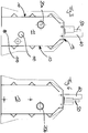
- a foundation pedestal comprises a carcass formed by side walls 10, a front end wall 11, a rear end wall 12, and an upper wall 13.
- the foundation base has no bottom wall in the exemplary embodiment, thus has an opening 14 down to the ground into which it is embedded. Penetrating rainwater can seep through.
- a bottom wall 14 may be provided which may be closed or provided with infiltration openings.
- the side walls 10 are reinforced by several ribs. These ribs are executed in the embodiment as vertical ribs and horizontally extending ribs.
- the side walls, the end walls and the upper wall may be made of steel or be cast from a solid surface, such as concrete. Depending on the requirements of the load capacity, an embodiment of said walls made of a polymer material may be possible.
- the cable conduits have an opening in the interior of the foundation base or are two cable conduit sections inserted into the end faces, so that a cable which is inserted into the foundation base at the end is led out within the foundation base and, for example, extended upward out of the foundation base by corresponding cable conduits 20c, d can be to thereby provide an attached to the foundation base device of the supply and disposal station with energy and to enable a corresponding signal and data communication.
- a front-side return line 30 and a rear-side return line 31 are further provided which lead into the foundation base.
- These return lines are pressure-free and form at the top of a port to which a corresponding drainage line of an upper component of the supply and disposal device can be connected.
- These return lines can be connected, for example, to catch basins to drain wastewater due to gravity and to be able to initiate into the foundation base or they can be connected to valve devices to absorb water at a drainage from the frost-prone running water or to receive as part of a flushing of these lines accumulating flushing water ,
- the pressure-free return lines 30, 31 open within the foundation base into a buffer tank 35a-d, which holds a volume of about 50 liters.
- This caching tank will, as in particular FIG. 5 can be seen, formed by a horizontally extending pipe section 35a and three outgoing vertically extending pipe sections 35b-d with a large pipe cross-section.
- the intermediate storage tank can also accommodate more than 100 liters, preferably more than 500 liters and in particular more than 1000 liters, for waste water, rinsing water and from a Drain water originating between store.
- the buffer can also be designed as a tank container.
- a vacuum sewer line 40 with corresponding vacuum sewer line 41 is present.
- a vacuum-pressurized sewer line can be connected, by means of which wastewater can be sucked out of a vehicle and introduced via the vacuum sewer line into the foundation base.
- This vacuum sewer line 40 is connected within the foundation base directly to a arranged in the front end side port 100 for a Abwassererdtechnisch.
- the connection 100 for the Abwassererd réelle is designed as a flange, for example, a pipe connection by means of electric welding sleeve or flexible pipe coupling and allows the connection of a vacuum-loaded Abiganerdtechnisch in frost-free area when inserting the foundation base in the ground.
- the vacuum sewer line 40 is connected in the flow direction behind the vacuum line connection 41 with a suction line 42 via a 2/2-way valve 43.
- This suction line 42 is connected to the intermediate storage tank inside the foundation base.
- This connection is realized in the embodiment by introducing the suction line 42 in a top-side sewer line.
- the suction line 42 may be formed as a suction hose.
- a fresh water conduit 50 leading out of the foundation base is provided, which identifies a fresh water conduit connection 51.
- an above-ground component of the supply and disposal station can be connected such that a local fresh water line or a fresh water hose is supplied with fresh water and allows the supply of a vehicle.
- a pressure-free fresh water return line 52 is connected to the fresh water line 50.
- This connection is realized via a 3/2-way valve 53.
- the 3/2-way valve can supply fresh water from the foundation base to the fresh water connection 51 in a first position and thereby enable the supply of a vehicle.
- the 3/2-way valve can derive fresh water from the fresh water connection 51 in the fresh water return line 52 and blocks the inflow of fresh water from the foundation base.
- the above-ground fresh water line can be dewatered and thereby made frost-resistant.
- the 3/2-way valve may optionally provide a third position in which fresh water from the fresh water inlet of the foundation base is led into the fresh water return line and the inflow to the fresh water connection 51 is blocked. This position can be used as a flushing position.
- the fresh water return line 52 opens into a return line 56 at the top of the foundation base.
- the return line 56 may, as well as the sewer pipe connections 30, 31 are executed and open into the arranged in the interior of the foundation base intermediate storage tank.
- a sensor 55 is provided for this purpose, which is symbolically arranged in the figure and detects the water level in the intermediate storage tank. Upon detection of a high level, this sensor 55 triggers a sensor signal, with which an extraction of the wastewater from the buffer tank is controlled.
- a Frischwassererd effetsan gleich 110 is arranged in addition to the vacuum-pressure sewage grounding connection 100, which comes to rest at the lowest point of the foundation base in the frost-proof soil when the foundation base is inserted into the ground.
- This Frischbergerd effetsan gleich 110 is also designed as a detachable or non-detachable pipe joint or pipe flange, as described above. Via this Frischwassererd effettechnischtechnisch 110 fresh water is led into the foundation base in order to bring this out of the foundation base on the fresh water line 50 can.
- the Frischbergerd Arthursan gleich 110 can be forwarded via a T-branch to the rear end face to connect thereto an opposite Frischwassererd effet with which another spaced foundation base is supplied with fresh water.
- two conduits 20c, 20d are used, which communicate with the cable conduit 20a, 20b and allow the lead-out or the introduction of energy signal or data cables from the top of the foundation base.
- a foundation pedestal like the foundation pedestal according to the invention described above, can be made in advance and spaced from the installation site and then transported to the installation site.
- the prefabricated foundation base is then inserted into the ground and connected by means of the terminals provided with the ground wires and the upward leading lines of the above-ground component of the supply and disposal station.
- the above-ground component of the supply and disposal station is at the same time attached to the foundation base and thereby erected stable.
- the foundation base with the intermediate storage tank therein can in particular be operated in such a way that gravitationally supplied waste water is temporarily stored in the foundation base in a temporary storage tank and also fresh water which is drained from the fresh water conduit by a drainage of the fresh water conduit after a filling operation in order to thereby produce frost protection. also discharged in this intermediate storage tank. This removal is also done by gravity.
- the level is then monitored by a sensor device, so that when a maximum level is reached, a suction can be triggered via a vacuum-charged sewer line.
- This vacuum-loaded sewer line can be the vacuum-loaded Abiganerd effet, with which also through the foundation base through a suction of waste water from a vehicle is carried out by means of negative pressure.
- FIG. 5 the basic structure of a supply device according to the invention can be seen.
- a top-side control unit O is mounted, which is supported by this foundation console E.
- the assembly of the operating unit O on the foundation head rail E is typically carried out detachably by means of a screw connection with a plurality of screws.
- the foundation console E and the operating unit O are delimited from each other along a terrain line T, which marks the Terrainober Design.
- angeorndet Within the foundation bracket E of the formed by the pipe sections 35a-d cache is angeorndet.
- the vertically upwardly facing pipe sections 35b-d are aligned with the sewer pipe connections 30, 31 and the return line 56 and are in fluid communication therewith.
- conduits 20a, b data and power lines are guided, which supply a control unit S in the above-ground control unit.
Landscapes
- Health & Medical Sciences (AREA)
- Life Sciences & Earth Sciences (AREA)
- Engineering & Computer Science (AREA)
- Hydrology & Water Resources (AREA)
- Public Health (AREA)
- Water Supply & Treatment (AREA)
- Sewage (AREA)
Priority Applications (5)
| Application Number | Priority Date | Filing Date | Title |
|---|---|---|---|
| DK18168331.9T DK3556952T3 (da) | 2018-04-19 | 2018-04-19 | Forsynings- og bortskaffelsesstation til et køretøj med sanitetsindretning |
| EP18168331.9A EP3556952B1 (fr) | 2018-04-19 | 2018-04-19 | Station d'alimentation et de décharge pour véhicules dotée de l'équipement sanitaire |
| LTEP18168331.9T LT3556952T (lt) | 2018-04-19 | 2018-04-19 | Tiekimo ir šalinimo stotis, skirta transporto priemonėms su sanitarine įranga |
| ES18168331T ES2904665T3 (es) | 2018-04-19 | 2018-04-19 | Estación de abastecimiento y de eliminación de desechos para vehículos con equipo sanitario |
| PL18168331T PL3556952T3 (pl) | 2018-04-19 | 2018-04-19 | Stacja zaopatrywania i usuwania odpadów dla pojazdów z urządzeniem sanitarnym |
Applications Claiming Priority (1)
| Application Number | Priority Date | Filing Date | Title |
|---|---|---|---|
| EP18168331.9A EP3556952B1 (fr) | 2018-04-19 | 2018-04-19 | Station d'alimentation et de décharge pour véhicules dotée de l'équipement sanitaire |
Publications (2)
| Publication Number | Publication Date |
|---|---|
| EP3556952A1 true EP3556952A1 (fr) | 2019-10-23 |
| EP3556952B1 EP3556952B1 (fr) | 2021-11-17 |
Family
ID=62046671
Family Applications (1)
| Application Number | Title | Priority Date | Filing Date |
|---|---|---|---|
| EP18168331.9A Active EP3556952B1 (fr) | 2018-04-19 | 2018-04-19 | Station d'alimentation et de décharge pour véhicules dotée de l'équipement sanitaire |
Country Status (5)
| Country | Link |
|---|---|
| EP (1) | EP3556952B1 (fr) |
| DK (1) | DK3556952T3 (fr) |
| ES (1) | ES2904665T3 (fr) |
| LT (1) | LT3556952T (fr) |
| PL (1) | PL3556952T3 (fr) |
Citations (4)
| Publication number | Priority date | Publication date | Assignee | Title |
|---|---|---|---|---|
| US4332681A (en) * | 1980-04-28 | 1982-06-01 | Jambry Jean Francois | Junction and connection terminal for the service of fixed or mobile premises in particular for the supply of a sanitary unit which may be itself attached to a caravan or a camping-car |
| DE10018711A1 (de) * | 1999-09-16 | 2001-03-22 | Knaus Gmbh Jandelsbrunn | Ver- und Entsorgungseinheit für Campinganlagen |
| DE202006012003U1 (de) * | 2006-08-03 | 2006-12-14 | Huber & Ranner Gmbh | Ver- und Entsorgungseinheit |
| DE202014003479U1 (de) * | 2014-04-28 | 2015-07-31 | Hugo Vogelsang Maschinenbau Gmbh | Unterflur-Wasserversorgungseinrichtung für Zugwaggons |
-
2018
- 2018-04-19 PL PL18168331T patent/PL3556952T3/pl unknown
- 2018-04-19 LT LTEP18168331.9T patent/LT3556952T/lt unknown
- 2018-04-19 DK DK18168331.9T patent/DK3556952T3/da active
- 2018-04-19 ES ES18168331T patent/ES2904665T3/es active Active
- 2018-04-19 EP EP18168331.9A patent/EP3556952B1/fr active Active
Patent Citations (4)
| Publication number | Priority date | Publication date | Assignee | Title |
|---|---|---|---|---|
| US4332681A (en) * | 1980-04-28 | 1982-06-01 | Jambry Jean Francois | Junction and connection terminal for the service of fixed or mobile premises in particular for the supply of a sanitary unit which may be itself attached to a caravan or a camping-car |
| DE10018711A1 (de) * | 1999-09-16 | 2001-03-22 | Knaus Gmbh Jandelsbrunn | Ver- und Entsorgungseinheit für Campinganlagen |
| DE202006012003U1 (de) * | 2006-08-03 | 2006-12-14 | Huber & Ranner Gmbh | Ver- und Entsorgungseinheit |
| DE202014003479U1 (de) * | 2014-04-28 | 2015-07-31 | Hugo Vogelsang Maschinenbau Gmbh | Unterflur-Wasserversorgungseinrichtung für Zugwaggons |
Also Published As
| Publication number | Publication date |
|---|---|
| ES2904665T3 (es) | 2022-04-05 |
| LT3556952T (lt) | 2022-03-10 |
| EP3556952B1 (fr) | 2021-11-17 |
| PL3556952T3 (pl) | 2022-03-28 |
| DK3556952T3 (da) | 2022-01-31 |
Similar Documents
| Publication | Publication Date | Title |
|---|---|---|
| EP0219622B1 (fr) | Dispositif pour contrôler au moins un courant de gaz | |
| DE102015106371A1 (de) | Unterflur-Wasserversorgungseinrichtung für Zugwaggons | |
| EP0699255B1 (fr) | Construction prefabriquee en beton arme ou dans un materiau equivalent | |
| DE3934633C1 (en) | Collector for rain water - tank sealed at bottom and mounted coaxially in drainage pit | |
| EP3556952B1 (fr) | Station d'alimentation et de décharge pour véhicules dotée de l'équipement sanitaire | |
| EP0570739B1 (fr) | Système de drainage | |
| DE102009053027A1 (de) | Regenwasser-Sicker/Rückhalte-System | |
| EP1515409B1 (fr) | Installation de commutation souterraine | |
| DE3310314C2 (fr) | ||
| DE19509466A1 (de) | Speicher für Flüssigkeiten | |
| DE19844354B4 (de) | Abwasser- und Fäkalien-Annahmeschacht für Abwasser sowie Fäkalien | |
| EP3702235B1 (fr) | Dispositif d'alimentation pour cellules sanitaires mobiles | |
| DE4312047C1 (de) | Vorrichtung zum Sammeln und Speichern von Sickerwässern einer Deponie | |
| EP0565483B1 (fr) | Bassin dans une installation d'eaux usées | |
| DE29709653U1 (de) | Toilettenanlage mit Unterdruckabsaugung | |
| WO2022167413A1 (fr) | Système de drainage d'eau de surface et son procédé de production | |
| DE102009025388A1 (de) | Vorrichtung zur Sicherung eines Behälters gegen ein Eindringen von Flüssigkeit und Abscheidevorrichtung | |
| DE102020105483A1 (de) | Speicherkanalisation | |
| DE29908811U1 (de) | Einrichtung zum Auffangen von Leichtflüssigkeiten und zu deren Rückhaltung geeigneter Abscheider | |
| WO1988003977A1 (fr) | Systeme d'evacuation sous pression des eaux usees et d'autres dechets liquides | |
| DE202014011094U1 (de) | Filtersubstratrinnenelement | |
| DE8502827U1 (de) | Flüssigkeitsspeicherraum mit einer Spüleinrichtung | |
| DE2746058A1 (de) | Vorrichtung zur entwaesserung von ausserhalb einer gebaeudewandung oder eines bodens des gebaeudes liegenden raeumen | |
| DE102024108980A1 (de) | Niederschlagsmanagement-system und -verfahren | |
| EP4610442A1 (fr) | Ensemble de construction et unité de régulation à utiliser dans un ensemble de construction |
Legal Events
| Date | Code | Title | Description |
|---|---|---|---|
| PUAI | Public reference made under article 153(3) epc to a published international application that has entered the european phase |
Free format text: ORIGINAL CODE: 0009012 |
|
| STAA | Information on the status of an ep patent application or granted ep patent |
Free format text: STATUS: THE APPLICATION HAS BEEN PUBLISHED |
|
| AK | Designated contracting states |
Kind code of ref document: A1 Designated state(s): AL AT BE BG CH CY CZ DE DK EE ES FI FR GB GR HR HU IE IS IT LI LT LU LV MC MK MT NL NO PL PT RO RS SE SI SK SM TR |
|
| AX | Request for extension of the european patent |
Extension state: BA ME |
|
| STAA | Information on the status of an ep patent application or granted ep patent |
Free format text: STATUS: REQUEST FOR EXAMINATION WAS MADE |
|
| 17P | Request for examination filed |
Effective date: 20200423 |
|
| RBV | Designated contracting states (corrected) |
Designated state(s): AL AT BE BG CH CY CZ DE DK EE ES FI FR GB GR HR HU IE IS IT LI LT LU LV MC MK MT NL NO PL PT RO RS SE SI SK SM TR |
|
| STAA | Information on the status of an ep patent application or granted ep patent |
Free format text: STATUS: EXAMINATION IS IN PROGRESS |
|
| 17Q | First examination report despatched |
Effective date: 20201126 |
|
| GRAP | Despatch of communication of intention to grant a patent |
Free format text: ORIGINAL CODE: EPIDOSNIGR1 |
|
| STAA | Information on the status of an ep patent application or granted ep patent |
Free format text: STATUS: GRANT OF PATENT IS INTENDED |
|
| INTG | Intention to grant announced |
Effective date: 20210602 |
|
| GRAS | Grant fee paid |
Free format text: ORIGINAL CODE: EPIDOSNIGR3 |
|
| GRAA | (expected) grant |
Free format text: ORIGINAL CODE: 0009210 |
|
| STAA | Information on the status of an ep patent application or granted ep patent |
Free format text: STATUS: THE PATENT HAS BEEN GRANTED |
|
| AK | Designated contracting states |
Kind code of ref document: B1 Designated state(s): AL AT BE BG CH CY CZ DE DK EE ES FI FR GB GR HR HU IE IS IT LI LT LU LV MC MK MT NL NO PL PT RO RS SE SI SK SM TR |
|
| REG | Reference to a national code |
Ref country code: GB Ref legal event code: FG4D Free format text: NOT ENGLISH |
|
| REG | Reference to a national code |
Ref country code: DE Ref legal event code: R096 Ref document number: 502018007854 Country of ref document: DE |
|
| REG | Reference to a national code |
Ref country code: IE Ref legal event code: FG4D Free format text: LANGUAGE OF EP DOCUMENT: GERMAN |
|
| REG | Reference to a national code |
Ref country code: AT Ref legal event code: REF Ref document number: 1448167 Country of ref document: AT Kind code of ref document: T Effective date: 20211215 |
|
| REG | Reference to a national code |
Ref country code: DK Ref legal event code: T3 Effective date: 20220125 |
|
| REG | Reference to a national code |
Ref country code: SE Ref legal event code: TRGR |
|
| REG | Reference to a national code |
Ref country code: NL Ref legal event code: MP Effective date: 20211117 |
|
| REG | Reference to a national code |
Ref country code: NO Ref legal event code: T2 Effective date: 20211117 |
|
| REG | Reference to a national code |
Ref country code: ES Ref legal event code: FG2A Ref document number: 2904665 Country of ref document: ES Kind code of ref document: T3 Effective date: 20220405 |
|
| PG25 | Lapsed in a contracting state [announced via postgrant information from national office to epo] |
Ref country code: RS Free format text: LAPSE BECAUSE OF FAILURE TO SUBMIT A TRANSLATION OF THE DESCRIPTION OR TO PAY THE FEE WITHIN THE PRESCRIBED TIME-LIMIT Effective date: 20211117 Ref country code: FI Free format text: LAPSE BECAUSE OF FAILURE TO SUBMIT A TRANSLATION OF THE DESCRIPTION OR TO PAY THE FEE WITHIN THE PRESCRIBED TIME-LIMIT Effective date: 20211117 Ref country code: BG Free format text: LAPSE BECAUSE OF FAILURE TO SUBMIT A TRANSLATION OF THE DESCRIPTION OR TO PAY THE FEE WITHIN THE PRESCRIBED TIME-LIMIT Effective date: 20220217 |
|
| REG | Reference to a national code |
Ref country code: SK Ref legal event code: T3 Ref document number: E 39219 Country of ref document: SK |
|
| PG25 | Lapsed in a contracting state [announced via postgrant information from national office to epo] |
Ref country code: IS Free format text: LAPSE BECAUSE OF FAILURE TO SUBMIT A TRANSLATION OF THE DESCRIPTION OR TO PAY THE FEE WITHIN THE PRESCRIBED TIME-LIMIT Effective date: 20220317 Ref country code: PT Free format text: LAPSE BECAUSE OF FAILURE TO SUBMIT A TRANSLATION OF THE DESCRIPTION OR TO PAY THE FEE WITHIN THE PRESCRIBED TIME-LIMIT Effective date: 20220317 Ref country code: NL Free format text: LAPSE BECAUSE OF FAILURE TO SUBMIT A TRANSLATION OF THE DESCRIPTION OR TO PAY THE FEE WITHIN THE PRESCRIBED TIME-LIMIT Effective date: 20211117 Ref country code: HR Free format text: LAPSE BECAUSE OF FAILURE TO SUBMIT A TRANSLATION OF THE DESCRIPTION OR TO PAY THE FEE WITHIN THE PRESCRIBED TIME-LIMIT Effective date: 20211117 Ref country code: GR Free format text: LAPSE BECAUSE OF FAILURE TO SUBMIT A TRANSLATION OF THE DESCRIPTION OR TO PAY THE FEE WITHIN THE PRESCRIBED TIME-LIMIT Effective date: 20220218 |
|
| PG25 | Lapsed in a contracting state [announced via postgrant information from national office to epo] |
Ref country code: SM Free format text: LAPSE BECAUSE OF FAILURE TO SUBMIT A TRANSLATION OF THE DESCRIPTION OR TO PAY THE FEE WITHIN THE PRESCRIBED TIME-LIMIT Effective date: 20211117 Ref country code: RO Free format text: LAPSE BECAUSE OF FAILURE TO SUBMIT A TRANSLATION OF THE DESCRIPTION OR TO PAY THE FEE WITHIN THE PRESCRIBED TIME-LIMIT Effective date: 20211117 Ref country code: EE Free format text: LAPSE BECAUSE OF FAILURE TO SUBMIT A TRANSLATION OF THE DESCRIPTION OR TO PAY THE FEE WITHIN THE PRESCRIBED TIME-LIMIT Effective date: 20211117 |
|
| REG | Reference to a national code |
Ref country code: DE Ref legal event code: R097 Ref document number: 502018007854 Country of ref document: DE |
|
| PLBE | No opposition filed within time limit |
Free format text: ORIGINAL CODE: 0009261 |
|
| STAA | Information on the status of an ep patent application or granted ep patent |
Free format text: STATUS: NO OPPOSITION FILED WITHIN TIME LIMIT |
|
| 26N | No opposition filed |
Effective date: 20220818 |
|
| PG25 | Lapsed in a contracting state [announced via postgrant information from national office to epo] |
Ref country code: AL Free format text: LAPSE BECAUSE OF FAILURE TO SUBMIT A TRANSLATION OF THE DESCRIPTION OR TO PAY THE FEE WITHIN THE PRESCRIBED TIME-LIMIT Effective date: 20211117 |
|
| PG25 | Lapsed in a contracting state [announced via postgrant information from national office to epo] |
Ref country code: SI Free format text: LAPSE BECAUSE OF FAILURE TO SUBMIT A TRANSLATION OF THE DESCRIPTION OR TO PAY THE FEE WITHIN THE PRESCRIBED TIME-LIMIT Effective date: 20211117 |
|
| PG25 | Lapsed in a contracting state [announced via postgrant information from national office to epo] |
Ref country code: MC Free format text: LAPSE BECAUSE OF FAILURE TO SUBMIT A TRANSLATION OF THE DESCRIPTION OR TO PAY THE FEE WITHIN THE PRESCRIBED TIME-LIMIT Effective date: 20211117 |
|
| PG25 | Lapsed in a contracting state [announced via postgrant information from national office to epo] |
Ref country code: IE Free format text: LAPSE BECAUSE OF NON-PAYMENT OF DUE FEES Effective date: 20220419 |
|
| PG25 | Lapsed in a contracting state [announced via postgrant information from national office to epo] |
Ref country code: HU Free format text: LAPSE BECAUSE OF FAILURE TO SUBMIT A TRANSLATION OF THE DESCRIPTION OR TO PAY THE FEE WITHIN THE PRESCRIBED TIME-LIMIT; INVALID AB INITIO Effective date: 20180419 |
|
| PG25 | Lapsed in a contracting state [announced via postgrant information from national office to epo] |
Ref country code: MK Free format text: LAPSE BECAUSE OF FAILURE TO SUBMIT A TRANSLATION OF THE DESCRIPTION OR TO PAY THE FEE WITHIN THE PRESCRIBED TIME-LIMIT Effective date: 20211117 Ref country code: CY Free format text: LAPSE BECAUSE OF FAILURE TO SUBMIT A TRANSLATION OF THE DESCRIPTION OR TO PAY THE FEE WITHIN THE PRESCRIBED TIME-LIMIT Effective date: 20211117 |
|
| PG25 | Lapsed in a contracting state [announced via postgrant information from national office to epo] |
Ref country code: MT Free format text: LAPSE BECAUSE OF FAILURE TO SUBMIT A TRANSLATION OF THE DESCRIPTION OR TO PAY THE FEE WITHIN THE PRESCRIBED TIME-LIMIT Effective date: 20211117 |
|
| PGFP | Annual fee paid to national office [announced via postgrant information from national office to epo] |
Ref country code: PL Payment date: 20250312 Year of fee payment: 8 |
|
| PGFP | Annual fee paid to national office [announced via postgrant information from national office to epo] |
Ref country code: LU Payment date: 20250417 Year of fee payment: 8 |
|
| PGFP | Annual fee paid to national office [announced via postgrant information from national office to epo] |
Ref country code: DE Payment date: 20250507 Year of fee payment: 8 |
|
| PGFP | Annual fee paid to national office [announced via postgrant information from national office to epo] |
Ref country code: GB Payment date: 20250423 Year of fee payment: 8 Ref country code: ES Payment date: 20250519 Year of fee payment: 8 Ref country code: DK Payment date: 20250423 Year of fee payment: 8 |
|
| PGFP | Annual fee paid to national office [announced via postgrant information from national office to epo] |
Ref country code: LT Payment date: 20250403 Year of fee payment: 8 |
|
| PGFP | Annual fee paid to national office [announced via postgrant information from national office to epo] |
Ref country code: NO Payment date: 20250422 Year of fee payment: 8 |
|
| PGFP | Annual fee paid to national office [announced via postgrant information from national office to epo] |
Ref country code: IT Payment date: 20250430 Year of fee payment: 8 Ref country code: BE Payment date: 20250422 Year of fee payment: 8 |
|
| PGFP | Annual fee paid to national office [announced via postgrant information from national office to epo] |
Ref country code: LV Payment date: 20250422 Year of fee payment: 8 |
|
| PGFP | Annual fee paid to national office [announced via postgrant information from national office to epo] |
Ref country code: FR Payment date: 20250422 Year of fee payment: 8 |
|
| PGFP | Annual fee paid to national office [announced via postgrant information from national office to epo] |
Ref country code: CH Payment date: 20250501 Year of fee payment: 8 |
|
| PGFP | Annual fee paid to national office [announced via postgrant information from national office to epo] |
Ref country code: AT Payment date: 20250416 Year of fee payment: 8 |
|
| PGFP | Annual fee paid to national office [announced via postgrant information from national office to epo] |
Ref country code: SK Payment date: 20250411 Year of fee payment: 8 |
|
| PGFP | Annual fee paid to national office [announced via postgrant information from national office to epo] |
Ref country code: CZ Payment date: 20250404 Year of fee payment: 8 |
|
| PGFP | Annual fee paid to national office [announced via postgrant information from national office to epo] |
Ref country code: SE Payment date: 20250423 Year of fee payment: 8 |
|
| PG25 | Lapsed in a contracting state [announced via postgrant information from national office to epo] |
Ref country code: TR Free format text: LAPSE BECAUSE OF FAILURE TO SUBMIT A TRANSLATION OF THE DESCRIPTION OR TO PAY THE FEE WITHIN THE PRESCRIBED TIME-LIMIT Effective date: 20211117 |