EP3556951B1 - Bloc de soupape sanitaire - Google Patents
Bloc de soupape sanitaire Download PDFInfo
- Publication number
- EP3556951B1 EP3556951B1 EP19168607.0A EP19168607A EP3556951B1 EP 3556951 B1 EP3556951 B1 EP 3556951B1 EP 19168607 A EP19168607 A EP 19168607A EP 3556951 B1 EP3556951 B1 EP 3556951B1
- Authority
- EP
- European Patent Office
- Prior art keywords
- insert
- base body
- receptacle
- valve block
- cartridge
- Prior art date
- Legal status (The legal status is an assumption and is not a legal conclusion. Google has not performed a legal analysis and makes no representation as to the accuracy of the status listed.)
- Active
Links
Images
Classifications
-
- E—FIXED CONSTRUCTIONS
- E03—WATER SUPPLY; SEWERAGE
- E03C—DOMESTIC PLUMBING INSTALLATIONS FOR FRESH WATER OR WASTE WATER; SINKS
- E03C1/00—Domestic plumbing installations for fresh water or waste water; Sinks
- E03C1/02—Plumbing installations for fresh water
- E03C1/04—Water-basin installations specially adapted to wash-basins or baths
-
- B—PERFORMING OPERATIONS; TRANSPORTING
- B01—PHYSICAL OR CHEMICAL PROCESSES OR APPARATUS IN GENERAL
- B01D—SEPARATION
- B01D35/00—Filtering devices having features not specifically covered by groups B01D24/00 - B01D33/00, or for applications not specifically covered by groups B01D24/00 - B01D33/00; Auxiliary devices for filtration; Filter housing constructions
- B01D35/02—Filters adapted for location in special places, e.g. pipe-lines, pumps, stop-cocks
- B01D35/04—Plug, tap, or cock filters filtering elements mounted in or on a faucet
-
- E—FIXED CONSTRUCTIONS
- E03—WATER SUPPLY; SEWERAGE
- E03C—DOMESTIC PLUMBING INSTALLATIONS FOR FRESH WATER OR WASTE WATER; SINKS
- E03C1/00—Domestic plumbing installations for fresh water or waste water; Sinks
- E03C1/02—Plumbing installations for fresh water
- E03C1/04—Water-basin installations specially adapted to wash-basins or baths
- E03C1/0401—Fixing a tap to the sanitary appliance or to an associated mounting surface, e.g. a countertop
-
- E—FIXED CONSTRUCTIONS
- E03—WATER SUPPLY; SEWERAGE
- E03C—DOMESTIC PLUMBING INSTALLATIONS FOR FRESH WATER OR WASTE WATER; SINKS
- E03C1/00—Domestic plumbing installations for fresh water or waste water; Sinks
- E03C1/02—Plumbing installations for fresh water
- E03C1/04—Water-basin installations specially adapted to wash-basins or baths
- E03C1/0403—Connecting the supply lines to the tap body
-
- E—FIXED CONSTRUCTIONS
- E03—WATER SUPPLY; SEWERAGE
- E03C—DOMESTIC PLUMBING INSTALLATIONS FOR FRESH WATER OR WASTE WATER; SINKS
- E03C1/00—Domestic plumbing installations for fresh water or waste water; Sinks
- E03C1/02—Plumbing installations for fresh water
- E03C2001/026—Plumbing installations for fresh water with flow restricting devices
Definitions
- the invention relates to a sanitary valve block according to the preamble of claim 1.
- Sanitary valve blocks comprising a base body with a cartridge holder, at least one water inlet, at least one water outlet, an inlet channel structure extending from the at least one water inlet to the cartridge holder and a discharge channel structure extending from the cartridge holder to the at least one water outlet, as well as a valve cartridge inserted into the base body, are used in various designs, e.g. for sanitary mixing and/or shut-off valves.
- a sanitary mixer fitting which has a fitting body with a cartridge receiving space formed between a cartridge receiving base and a cartridge receiving cover and a mixing valve cartridge arranged in the cartridge receiving space.
- a mixer valve cartridge disclosed in the disclosure DE 10 2011 085 346 A1 The sanitary fitting disclosed includes a receiving component that can be connected to a base component, which has a receiving space for a valve cartridge and a base for connecting supply lines, wherein a fitting housing completely surrounds the base component and the receiving component with the exception of an access for the valve cartridge and is attached to the receiving component.
- the disclosure DE 10 2012 212 302 A1 discloses a sanitary fitting which has a fitting housing with a substantially straight interior for supply lines and/or discharge lines and a receptacle for a mixer cartridge branching off from the interior.
- a connecting insert is arranged in the interior, which has connections for at least one supply line on one end face.
- An adapter insert is arranged between the connecting insert and the receptacle for the mixer cartridge, with which the transition between the connecting insert and the mixer cartridge can be adapted to the branch angle of the branch of the mixer cartridge receptacle from the interior.
- an insert element which has a particle sieve and/or a flow regulator, on a water outlet element, in particular on an outlet pipe and preferably on its outlet-side End area.
- the particle sieve is intended to hold back disruptive particles such as lime particles, sand particles and the like.
- the term flow regulator is intended to cover any conventional elements that have a significant influence on the water flow rate or the water flow rate. This includes in particular flow limiters, i.e. elements that limit the flow rate, aerators, i.e. elements that aerate the water flowing through, backflow preventers, i.e. elements that prevent water backflow, and jet formers, i.e. jet-forming elements.
- Jet formers are often part of insert elements arranged at the water outlet of an outlet pipe.
- Various insert elements of this type for water outlet pipes are described in the published specification DE 10 2008 012 388 A1 and the patent documents DE 10 2005 003 404 B3 and DE 10 2006 062 983 B3 revealed.
- a safety device for a pressureless mixer which comprises a particle sieve, a first and a second backflow preventer and a quantity-limiting flow regulator in a tubular housing body one behind the other in the direction of flow.
- Sanitary valve blocks according to the preamble of claim 1 include an insert receptacle extending into the discharge channel structure, wherein optionally one or more further insert receptacles can extend into the inlet channel structure or into the discharge channel structure, and an insert element inserted into the insert receptacle, which has a particle sieve and/or a flow regulator.
- Such and similar sanitary valve blocks with an insert receptacle extending into the inlet channel structure or into the discharge channel structure are described in the utility model DE 297 20 408 U1 , the disclosure documents US 2004/0133975 A1 , US 2009/0242052 A1 , US 2017/0328040 A1 , EP 0 694 721 A1 and EP 2 937 476 A1 and the patent specification US 6,321,777 B1 disclosed.
- disclosure documents CA 2 843 596 A1 , EP 2 365 237 A1 , US 2003/132306 A1 , CN 101 949 462 A , CN 1 869 486 A , WO 2006/077109 A1 Further sanitary valve blocks are disclosed.
- the invention is based on the technical problem of providing a sanitary valve block of the type mentioned at the outset, which is improved in its functionality compared to the conventional sanitary valve blocks mentioned above and/or offers manufacturing advantages.
- the invention solves this problem by providing a sanitary valve block with the features of claim 1.
- An insert element is integrated into the sanitary valve block, which contains a particle sieve and/or a flow regulator.
- the base body of the sanitary valve block has an insert receptacle into which the insert element is inserted.
- the insert receptacle extends into the discharge channel structure, which extends from the cartridge receptacle to at least one water outlet. Due to the advantageous integration of the insert element into the sanitary valve block and specifically into an insert receptacle in its base body, the arrangement of such an insert element at another point of a sanitary water flow path in which the sanitary valve block is located can be omitted.
- the sanitary valve block when using the sanitary valve block in a sanitary outlet fitting, the arrangement of such an insert element at the outlet end of an associated outlet line or an associated outlet pipe can be omitted.
- the sanitary valve block according to the invention also enables the integration of the insert element with particle sieve and/or flow regulator in a compact design.
- the base body of the sanitary valve block can preferably be assembled from a few components or manufactured in one piece.
- the insert holder is formed by a blind hole in the base body of the sanitary valve block, with the discharge channel structure opening transversely into the blind hole at a first position and opening transversely out of the blind hole at a second position axially spaced from the first.
- At least one water inlet on the one hand and the insert receptacle on the other hand are located on opposite sides of the base body of the sanitary valve block.
- the insert element inserted into the insert receptacle thus remains accessible on the side of the base body opposite the at least one water inlet, whereby this side can in particular be the assembly side of the base body.
- the sanitary valve block contains a fastening device which is designed for detachable fastening of the base body, wherein it can be operated from an assembly side of the base body.
- the insert element can be inserted into the insert holder from this assembly side of the base body.
- the insert element is detachably inserted into the insert holder and can then, if required, be removed from the insert holder from the assembly side of the base body, for example for maintenance purposes or to clean or replace the insert element.
- the base body can be dismantled from its location of use from the assembly side. If the sanitary valve block is installed in a sanitary fitting, only the relevant mounting side of the base body needs to remain accessible or be made accessible in order to insert and remove the insert element or to assemble and disassemble the valve block base body. This can make maintenance work on the sanitary valve block of the sanitary fitting comparatively easy.
- the insert element is designed as a cylindrical insert cartridge, which has a peripheral mouth opening and a frontal mouth opening in fluid communication with the latter on a first end face, as well as a tool interface for an assembly/disassembly tool on a second end face.
- the insert element can be removed from the
- the valve block base body can be mounted in the insert holder or removed from it using a suitable assembly/dismantling tool from the mounting side.
- the tool interface can be one for a screwdriver, a polygonal wrench, etc.
- the insert cartridge has a cylindrical insert body with the first and the second end face, wherein the peripheral and the end opening are formed on the insert body. Between the first end face and the peripheral opening, the cylindrical insert body forms a sleeve-shaped receptacle for the particle sieve and/or the flow regulator.
- the insert holder and the cartridge holder are each formed cylindrically in the base body, in such a way that a longitudinal axis of the cylindrical insert holder runs perpendicular to a longitudinal axis of the cylindrical cartridge holder.
- this can be advantageous for the compactness or the design and/or the water flow behavior of the base body of the sanitary valve block.
- the at least one water outlet opens out of the base body transversely to the longitudinal axis of the cylindrical insert holder and transversely to the longitudinal axis of the cylindrical cartridge holder. This can also optimize the compactness and/or the design and/or the water flow behavior of the base body of the sanitary valve block for corresponding applications.
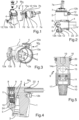
- the illustrated sanitary valve block has a base body 1 which includes a cartridge holder 2, at least one water inlet 3, at least one water outlet 4, an inlet channel structure 5 extending from the at least one water inlet 3 to the cartridge holder 2 and a discharge channel structure 6 extending from the cartridge holder 2 to the at least one water outlet 4.
- the base body 1 is individually in Fig. 3 shown.
- the Fig. 2 and 4 show the sanitary valve block in an installed state in which it is located at a desired place of use, with the associated environment in the Fig. 2 and 4 with the exception of a water discharge pipe 21 is not shown.
- the water discharge pipe 21 is coupled with its inlet end to the water outlet 4, e.g. using a detachable and sealing snap-in plug connection unit 22.
- the sanitary valve block further comprises a valve cartridge 7 inserted into the cartridge holder 2.
- the valve cartridge 7 is of any conventional design, which therefore requires no further explanation here.
- the valve cartridge 7 can, for example, be one for a mixing and/or shut-off valve, as is customary for sanitary fittings and in particular sanitary outlet fittings.
- the valve cartridge 7 can be used for a sanitary outlet fitting of the conventional single-lever operating type, for which the valve cartridge 7 then has an associated lever coupling nozzle 7a.
- the at least one water inlet 3 can, for example, comprise a cold water inlet and a hot water inlet, and the inlet channel structure 5 accordingly then contains a cold water supply and a separate hot water supply to the cartridge holder 2 and thus to the valve cartridge 7 inserted into the cartridge holder 2, and the discharge channel structure 6 accordingly contains one or more mixed water discharge channels that lead to the one or more water outlets 4 as mixed water outlets.
- the valve cartridge 7 has a cold water inlet 7b, a hot water inlet 7c and at least one mixed water outlet 7d.
- valve cartridge 7 For the correct positional, rotation-proof coupling of the valve cartridge 7 with its inlets and outlets 7b, 7c, 7d to the inlet channel structure 5 and the discharge channel structure 6, the valve cartridge 7 optionally has one or more rotary position pins 7e, which engage in corresponding pin receptacles 2a of the cartridge receptacle 2.
- the sanitary valve block further includes an insert receptacle 8 extending into the discharge channel structure 6 and an insert element 9 inserted into the insert receptacle 8, which has a particle sieve 10 and/or a flow regulator 11.
- the insert element 9 has both the particle sieve 10 and the flow regulator 11; in alternative designs, it only has the particle sieve 10 or only the flow regulator 11.
- the flow regulator 11 can also be, for example, a limiter, an aerator or a backflow preventer.
- the insert holder 8 and the cartridge holder 2 are each cylindrical and formed with mutually perpendicular longitudinal axes on the base body 1.
- the at least one water outlet 4 opens out of the base body 1 transversely to the longitudinal axis of the insert holder 8 and transversely to the longitudinal axis of the cartridge holder 2.
- the insert holder 8 and the cartridge holder 2 are formed with mutually non-perpendicular, e.g. parallel, longitudinal axes and/or with a non-cylindrical shape on the base body 1.
- the at least one water outlet 4 does not open out of the base body 1 transversely to the longitudinal axis of the insert holder 8 and/or not transversely to the longitudinal axis of the cartridge holder 2, but e.g. parallel or obliquely to at least one of these longitudinal axes.
- the at least one water inlet 3 on the one hand and the insert receptacle 8 on the other hand are located on opposite sides of the base body 1.
- the at least one water inlet 3 on the one hand and the insert receptacle 8 on the other hand are located on the same side of the base body 1 or on two adjacent, adjoining sides of the base body 1.
- the insert holder 8 is formed by a blind hole 24 in the base body, whereby in the example shown the discharge channel structure 6 opens transversely into the blind hole at axially spaced positions and opens transversely out of the blind hole.
- the insert holder 8 is designed differently, e.g. as a continuous hole in the base body 1.
- the sanitary valve block also includes a fastening device 12 for detachably fastening the base body 1.
- the fastening device 12 is designed to be operated from a mounting side M S of the base body 1.
- the insert element 9 can be inserted into the insert holder 8 from the mounting side M S of the base body 1.
- the mounting side M S in the embodiment shown is the one shown in the Fig. 1 and 4 upper and lower Fig. 3 right side and in Fig. 2 the top view of the base body 1.
- the fastening device 12 comprises one or more, e.g. two, screw connections, each with a screw receiving opening 12a and a fastening screw 12b that can be inserted therein.
- the fastening device 12 has other detachable fastening means, as are familiar to those skilled in the art as alternatives to screw connections, which does not require any further explanation here, e.g. detachable plug-in, snap-in, clip or locking connection means.
- the sanitary valve block with its base body 1 can be detachably fastened to a designated application or place of use, such as in a sanitary fitting, e.g. a sanitary outlet fitting.
- the respective fastening screw 12b can be operated for this purpose from the assembly side M S of the base body 1.
- the receiving openings 12a for the fastening screws 12b are formed on corresponding fastening flanges 13a, 13b, which protrude suitably from the base body 1.
- the insert element 9 is designed as a cylindrical insert cartridge 14, which has a peripheral mouth opening 15 and a frontal mouth opening 16 in fluid communication with the latter on a first end face 17. Furthermore, the cylindrical insert cartridge 14 has a tool interface 19 for an associated assembly/dismantling tool on a second end face 18.
- This tool can be, for example, a polygonal wrench, so that in this case the tool interface 19 is designed as a tool holder with a suitable polygonal cross-section.
- the insert cartridge 14 has a sealing ring 20, with which the insert holder 8 is sealed to the outside when the insert element 9 is inserted.
- the insert cartridge 14 can, for example, as shown, have a cylindrical insert body 14a with the first and second end faces 17, 18, wherein the peripheral mouth opening 15 and the end face mouth opening 16 are formed on the cylindrical insert body 14a. Between the first end face 17 and the peripheral mouth opening 15, the insert body 14a forms a sleeve-shaped receptacle 23 for the particle sieve 10 and/or the flow regulator 11. The particle sieve 10 and/or the flow regulator 11 can be inserted into the receptacle 23 and held therein.
- the insert element 9 is implemented in a different way. This includes implementations using a non-cylindrical insert body and/or without the mentioned tool interface, whereby the insert element can then be designed, for example, in such a way that it can be assembled/disassembled directly by the user without the need for a tool.
- the mouth openings are designed differently, e.g. in the form of two front-side mouth openings or two peripheral mouth openings.
- the particle sieve and/or the flow regulator is/are an integral part of a correspondingly designed insert body of the insert element.
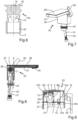
- the Fig. 7 to 9 illustrate an exemplary use of the sanitary valve block in one of the embodiments according to the Fig. 1 to 6 and the above-mentioned alternatives for a sanitary mixing and/or shut-off valve of the single-lever operating type in a sanitary water outlet fitting 25.
- the water outlet fitting 25 includes a fitting body 26 with an open top acting as a maintenance opening 27.
- the open top, ie the maintenance opening 27, is closed with a cover 28 which is detachably attached to the fitting body 26.
- the sanitary water outlet fitting 25 can, for example, be one such as that described in the published specification DE 10 2018 205 747 A1 to which reference can be made for additional details.
- the sanitary valve block with the base body 1 and with the valve cartridge 7 inserted into its cartridge holder 2 and with the insert element 9 inserted into the insert holder 8 is arranged in the fitting base body 26.
- An operating lever 29 is coupled to the lever coupling nozzle 7a of the valve cartridge 7 as an operating element.
- Associated water supply lines, specifically a cold water line 30 and a hot water line 31 are led into the fitting base body 26 to at least one water inlet 3 of the base body 1 of the sanitary valve block.
- the water outlet fitting 25 can be attached to a desired location, e.g. to a washbasin, a bathtub or a kitchen sink, by means of a fastening base 32 arranged on a fastening side of the fitting base body 26.
- the corresponding Fig. 2 The water discharge pipe 21 connected to at least one water outlet 4 of the base body 1 of the sanitary valve block leads in this Embodiment to a jet-forming water outlet element 33 coupled to its downstream end, from which supplied water emerges in a desired jet shape.
- the sanitary valve block is fixed, ie screwed, to the fitting base body 26 by means of the fastening device 12 with the associated screw receiving openings 12a and the associated fastening screws 12b inside the latter.
- the fastening device 12 and the insert element 9 are accessible via the maintenance opening 27 when the cover 28 is removed, ie the sanitary valve block is held in the fitting body 26 in a position in which its mounting side M S points upwards, ie in the direction of the top side or maintenance opening 27 of the fitting body 26 which is open when the cover 28 is removed.
- the insert element 9 can thus be removed from the water outlet fitting 25 in a simple manner by removing the cover 28 and then dismantling it from its insert holder 8, e.g. for maintenance purposes.
- the entire sanitary valve block can be removed from the fitting base body 26 by loosening the fastening device 12 or its fastening screws 12b after removing the top cover 28 of the outlet fitting 25, or vice versa can be reinstalled in the fitting base body 26 by inserting it into the latter and securing it there using the fastening device 12.
- the operating lever 29 only needs to be removed from the lever coupling socket 7a or reattached to it.
- the insert element 9 integrated into the sanitary valve block already contains the particle sieve 10 and/or the flow regulator 11, such a particle sieve or such a flow regulator in the area of the jet-forming water outlet element 33 can be omitted in the water outlet fitting 25.
- the water outlet element 33 can be freely designed with regard to its jet-forming water outlet function, without having to take into account a particle sieve and/or a flow regulator to be placed there.
- the sanitary valve block with the integrated insert element 9 can be installed in a compact design in the fitting base body 26 of the water outlet fitting in a space-saving manner.
- the invention provides a sanitary valve block in which an insert element with a particle sieve and/or flow regulator is advantageously integrated, wherein preferably a fastening device for releasably fastening the base body of the sanitary valve block can be operated from a single mounting side of the base body and the insert element can be inserted into and removed from its insert receptacle on the base body of the sanitary valve block from this mounting side of the base body.
Landscapes
- Engineering & Computer Science (AREA)
- Water Supply & Treatment (AREA)
- Health & Medical Sciences (AREA)
- Life Sciences & Earth Sciences (AREA)
- Hydrology & Water Resources (AREA)
- Public Health (AREA)
- Chemical & Material Sciences (AREA)
- Chemical Kinetics & Catalysis (AREA)
- Valve Housings (AREA)
- Domestic Plumbing Installations (AREA)
- Multiple-Way Valves (AREA)
Claims (7)
- Bloc de vanne sanitaire, comprenant- un corps de base (1) ayant un logement de cartouche (2), au moins une entrée d'eau (3), au moins une sortie d'eau (4), une structure de canal d'alimentation (5) s'étendant de ladite au moins une entrée d'eau au logement de cartouche (2), et une structure de canal d'évacuation (6) s'étendant du logement de cartouche (2) à ladite au moins une sortie d'eau (4),- une cartouche de vanne (7) mise en place dans le logement de cartouche (2),- un logement d'insertion (8) s'étendant jusque dans la structure de canal d'évacuation (6), et- un élément d'insertion (9) mis en place dans le logement d'insertion (8), qui présente un tamis à particules (10) et/ou un régulateur de débit (11),
caractérisé en ce que- le logement d'insertion (8) est formé par un trou borgne (24) dans le corps de base (1), la structure de canal d'évacuation (6) débouchant transversalement dans le trou borgne (24) et débouchant transversalement hors du trou borgne (24) à des positions espacées axialement l'une de l'autre. - Bloc de vanne sanitaire selon la revendication 1,
caractérisé en outre en ce que ladite au moins une entrée d'eau (3), d'une part, et le logement d'insertion (8), d'autre part, se trouvent sur des côtés opposés du corps de base (1). - Bloc de vanne sanitaire selon la revendication 1 ou 2,
caractérisé en outre par un dispositif de fixation (12) pour la fixation amovible du corps de base (1), le dispositif de fixation (12) étant conçu pour la commande depuis un côté de montage (MS) du corps de base (1), et l'élément d'insertion (9) pouvant être mis en place dans le logement d'insertion (8) depuis le côté de montage (MS) du corps de base (1). - Bloc de vanne sanitaire selon l'une des revendications 1 à 3,
caractérisé en outre en ce que l'élément d'insertion (9) est réalisé sous la forme d'une cartouche d'insertion cylindrique (14) qui présente sur une première face frontale (17) une ouverture d'embouchure périphérique (15) et une ouverture d'embouchure frontale (16) en liaison fluidique avec celle-ci, et sur une deuxième face frontale (18) une interface d'outil (19) pour un outil de montage/démontage. - Bloc de vanne sanitaire selon la revendication 4,
caractérisé en outre en ce que la cartouche d'insertion (14) présente un corps d'insertion cylindrique (14a) avec les première et deuxième faces frontales (17, 18), sur lequel sont formées l'ouverture d'embouchure périphérique (15) et l'ouverture d'embouchure frontale (16) et qui forme, entre la première face frontale (17) et l'ouverture d'embouchure périphérique (15), un logement en forme de manchon (23) pour le tamis à particules (10) et/ou le régulateur de débit (11). - Bloc de vanne sanitaire selon l'une des revendications 1 à 5,
caractérisé en outre en ce que le logement d'insertion (8) et le logement de cartouche (2) sont chacun réalisés sur le corps de base (1) en ayant des formes cylindriques et des axes longitudinaux perpendiculaires l'un à l'autre. - Bloc de vanne sanitaire selon la revendication 6,
caractérisé en outre en ce que ladite au moins une sortie d'eau (3) débouche hors du corps de base (1) transversalement à l'axe longitudinal du logement d'insertion (8) et transversalement à l'axe longitudinal du logement de cartouche (2).
Applications Claiming Priority (1)
| Application Number | Priority Date | Filing Date | Title |
|---|---|---|---|
| DE102018205748.6A DE102018205748A1 (de) | 2018-04-16 | 2018-04-16 | Sanitärventilblock |
Publications (2)
| Publication Number | Publication Date |
|---|---|
| EP3556951A1 EP3556951A1 (fr) | 2019-10-23 |
| EP3556951B1 true EP3556951B1 (fr) | 2024-11-20 |
Family
ID=66105164
Family Applications (1)
| Application Number | Title | Priority Date | Filing Date |
|---|---|---|---|
| EP19168607.0A Active EP3556951B1 (fr) | 2018-04-16 | 2019-04-11 | Bloc de soupape sanitaire |
Country Status (3)
| Country | Link |
|---|---|
| EP (1) | EP3556951B1 (fr) |
| CN (1) | CN110387925B (fr) |
| DE (1) | DE102018205748A1 (fr) |
Citations (4)
| Publication number | Priority date | Publication date | Assignee | Title |
|---|---|---|---|---|
| US20030132306A1 (en) * | 2002-01-15 | 2003-07-17 | Chiu Edward Samson | Mixing faucet having multiple discharges |
| WO2006077109A1 (fr) * | 2005-01-24 | 2006-07-27 | Neoperl Gmbh | Unite d'ecoulement sanitaire |
| CN1869486A (zh) * | 2006-04-26 | 2006-11-29 | 邹建仁 | 一种具有向上喷水功能的水龙头 |
| CN101949462A (zh) * | 2010-10-09 | 2011-01-19 | 厦门市易洁卫浴有限公司 | 一种多功能出水龙头 |
Family Cites Families (19)
| Publication number | Priority date | Publication date | Assignee | Title |
|---|---|---|---|---|
| DE3632080A1 (de) * | 1986-09-20 | 1988-03-24 | Seppelfricke Geb Gmbh | Eckventil fuer gebaeudewasserleitungen |
| GB2291693B (en) * | 1994-07-26 | 1998-07-08 | Caradon Mira Ltd | Improvements in or relating to mixers for water supply installations |
| DE19701846C2 (de) | 1997-01-21 | 2001-01-25 | Hansgrohe Ag | Sicherungseinrichtung für einen drucklosen Mischer sowie deren Verwendung zur Absicherung eines drucklosen Boilers |
| DE29703335U1 (de) | 1997-02-25 | 1997-04-10 | Dieter Wildfang GmbH, 79379 Müllheim | Rückflußverhinderer |
| IT1290596B1 (it) * | 1997-03-14 | 1998-12-10 | Sani Taps S R L | Rubinetto per la regolazione di un liquido |
| US6321777B1 (en) * | 2000-05-04 | 2001-11-27 | Faucet Wu | Wall-type shower faucet influent load control fixture |
| US6802424B2 (en) * | 2003-01-14 | 2004-10-12 | Globe Union Industrial Corp. | Strainer in shower bath tap valve |
| DE102006062983B3 (de) | 2006-09-28 | 2015-02-05 | Neoperl Gmbh | Strahlregler |
| DE102008012388B4 (de) | 2008-03-04 | 2010-01-14 | Neoperl Gmbh | Sanitäre Funktionseinheit |
| CN100545493C (zh) * | 2008-03-31 | 2009-09-30 | 艾欧史密斯(中国)热水器有限公司 | 调温混水阀 |
| EP2365237A1 (fr) * | 2010-03-11 | 2011-09-14 | Valvulas Arco, S.L. | Valve à trois voies |
| MX354313B (es) * | 2011-07-31 | 2018-02-26 | Sloan Valve Co | Grifos automaticos. |
| DE102011085346B4 (de) | 2011-10-27 | 2014-07-31 | Hansgrohe Se | Sanitärarmatur |
| DE102012212302C5 (de) | 2012-07-13 | 2019-11-21 | Hansgrohe Se | Sanitärarmatur |
| DE102014200717A1 (de) | 2014-01-16 | 2015-07-16 | Hansgrohe Se | Sanitäre Mischerarmatur |
| CN103953785B (zh) * | 2014-04-23 | 2016-07-13 | 江门市霏尼格斯淋浴制品科技有限公司 | 一种预埋水龙头结构总成 |
| WO2016131472A1 (fr) * | 2015-02-16 | 2016-08-25 | Oblamatik Ag | Soupape pour réguler le flux d'eau dans une conduite sanitaire |
| US10280598B2 (en) * | 2016-05-16 | 2019-05-07 | Dahata Inc. | Faucet assembly |
| DE202016004959U1 (de) | 2016-08-09 | 2016-08-24 | Hansgrohe Se | Schlauchanschlussvorrichtung |
-
2018
- 2018-04-16 DE DE102018205748.6A patent/DE102018205748A1/de not_active Ceased
-
2019
- 2019-04-11 EP EP19168607.0A patent/EP3556951B1/fr active Active
- 2019-04-16 CN CN201910304371.1A patent/CN110387925B/zh active Active
Patent Citations (4)
| Publication number | Priority date | Publication date | Assignee | Title |
|---|---|---|---|---|
| US20030132306A1 (en) * | 2002-01-15 | 2003-07-17 | Chiu Edward Samson | Mixing faucet having multiple discharges |
| WO2006077109A1 (fr) * | 2005-01-24 | 2006-07-27 | Neoperl Gmbh | Unite d'ecoulement sanitaire |
| CN1869486A (zh) * | 2006-04-26 | 2006-11-29 | 邹建仁 | 一种具有向上喷水功能的水龙头 |
| CN101949462A (zh) * | 2010-10-09 | 2011-01-19 | 厦门市易洁卫浴有限公司 | 一种多功能出水龙头 |
Also Published As
| Publication number | Publication date |
|---|---|
| CN110387925B (zh) | 2021-03-09 |
| DE102018205748A1 (de) | 2019-10-17 |
| EP3556951A1 (fr) | 2019-10-23 |
| CN110387925A (zh) | 2019-10-29 |
Similar Documents
| Publication | Publication Date | Title |
|---|---|---|
| EP3408458B1 (fr) | Pièce d'écoulement sanitaire, article de robinetterie sanitaire et utilisation d'une pièce d'écoulement | |
| EP3290598B1 (fr) | Socle de raccordement pour robinetterie sanitaire pourvu d'une colonne d'armature reposant sur le sol | |
| EP1006242B1 (fr) | Système de robinetteries sanitaires | |
| AT409775B (de) | Mehrzahl von sanitären mischarmaturen | |
| EP3447201B1 (fr) | Armature sanitaire pourvu d'un mécanisme d'insertion | |
| DE102007043309B4 (de) | Sanitärarmatur | |
| EP2182122A1 (fr) | Armature de pomme à prise de contact en saillie | |
| DE102016000766B4 (de) | Sanitäres Auslaufstück, Sanitärarmatur und Verwendung eines Auslaufstücks | |
| DE102004014126B3 (de) | Sanitär-Armatur zur Unterputz-Montage | |
| DE4421387B4 (de) | Einlochmischbatterie | |
| DE102013205250B4 (de) | Rohranschlussadapter und Sanitärarmatur | |
| EP0942104A2 (fr) | Robinetterie sanitaire | |
| EP3556951B1 (fr) | Bloc de soupape sanitaire | |
| DE8703606U1 (de) | Auslaufarmatur | |
| EP0309397B1 (fr) | Dispositif pour raccordement en eau d'installations sanitaires | |
| CH655771A5 (en) | Single-hole mixing tap, especially for the kitchen sector | |
| DE4002798C2 (de) | Sanitärbatterie für Aufputzanbringung | |
| DE102005052919B4 (de) | Mischbatterie | |
| DE102018200530B4 (de) | Fluidleitungseinsatz | |
| EP0253388B1 (fr) | Dispositif de réglage de conduites d'arrosage de champs | |
| DE9309418U1 (de) | Hebelmischarmatur | |
| EP3556950A1 (fr) | Robinetterie sanitaire de sortie d'eau | |
| DE10212477B4 (de) | Wasserarmatur mit einer Bodenplatte | |
| EP0855635B1 (fr) | Robinetterie sanitaire | |
| EP1390586A1 (fr) | Bloc de robinetterie sanitaire |
Legal Events
| Date | Code | Title | Description |
|---|---|---|---|
| PUAI | Public reference made under article 153(3) epc to a published international application that has entered the european phase |
Free format text: ORIGINAL CODE: 0009012 |
|
| STAA | Information on the status of an ep patent application or granted ep patent |
Free format text: STATUS: THE APPLICATION HAS BEEN PUBLISHED |
|
| AK | Designated contracting states |
Kind code of ref document: A1 Designated state(s): AL AT BE BG CH CY CZ DE DK EE ES FI FR GB GR HR HU IE IS IT LI LT LU LV MC MK MT NL NO PL PT RO RS SE SI SK SM TR |
|
| AX | Request for extension of the european patent |
Extension state: BA ME |
|
| STAA | Information on the status of an ep patent application or granted ep patent |
Free format text: STATUS: REQUEST FOR EXAMINATION WAS MADE |
|
| 17P | Request for examination filed |
Effective date: 20200420 |
|
| RBV | Designated contracting states (corrected) |
Designated state(s): AL AT BE BG CH CY CZ DE DK EE ES FI FR GB GR HR HU IE IS IT LI LT LU LV MC MK MT NL NO PL PT RO RS SE SI SK SM TR |
|
| STAA | Information on the status of an ep patent application or granted ep patent |
Free format text: STATUS: EXAMINATION IS IN PROGRESS |
|
| 17Q | First examination report despatched |
Effective date: 20210628 |
|
| GRAP | Despatch of communication of intention to grant a patent |
Free format text: ORIGINAL CODE: EPIDOSNIGR1 |
|
| STAA | Information on the status of an ep patent application or granted ep patent |
Free format text: STATUS: GRANT OF PATENT IS INTENDED |
|
| INTG | Intention to grant announced |
Effective date: 20240716 |
|
| RIC1 | Information provided on ipc code assigned before grant |
Ipc: E03C 1/02 20060101ALN20240705BHEP Ipc: E03C 1/04 20060101AFI20240705BHEP |
|
| GRAS | Grant fee paid |
Free format text: ORIGINAL CODE: EPIDOSNIGR3 |
|
| GRAA | (expected) grant |
Free format text: ORIGINAL CODE: 0009210 |
|
| STAA | Information on the status of an ep patent application or granted ep patent |
Free format text: STATUS: THE PATENT HAS BEEN GRANTED |
|
| AK | Designated contracting states |
Kind code of ref document: B1 Designated state(s): AL AT BE BG CH CY CZ DE DK EE ES FI FR GB GR HR HU IE IS IT LI LT LU LV MC MK MT NL NO PL PT RO RS SE SI SK SM TR |
|
| REG | Reference to a national code |
Ref country code: GB Ref legal event code: FG4D Free format text: NOT ENGLISH |
|
| REG | Reference to a national code |
Ref country code: CH Ref legal event code: EP |
|
| REG | Reference to a national code |
Ref country code: DE Ref legal event code: R096 Ref document number: 502019012496 Country of ref document: DE |
|
| REG | Reference to a national code |
Ref country code: IE Ref legal event code: FG4D Free format text: LANGUAGE OF EP DOCUMENT: GERMAN |
|
| REG | Reference to a national code |
Ref country code: LT Ref legal event code: MG9D |
|
| REG | Reference to a national code |
Ref country code: NL Ref legal event code: MP Effective date: 20241120 |
|
| PG25 | Lapsed in a contracting state [announced via postgrant information from national office to epo] |
Ref country code: PT Free format text: LAPSE BECAUSE OF FAILURE TO SUBMIT A TRANSLATION OF THE DESCRIPTION OR TO PAY THE FEE WITHIN THE PRESCRIBED TIME-LIMIT Effective date: 20250320 Ref country code: HR Free format text: LAPSE BECAUSE OF FAILURE TO SUBMIT A TRANSLATION OF THE DESCRIPTION OR TO PAY THE FEE WITHIN THE PRESCRIBED TIME-LIMIT Effective date: 20241120 Ref country code: IS Free format text: LAPSE BECAUSE OF FAILURE TO SUBMIT A TRANSLATION OF THE DESCRIPTION OR TO PAY THE FEE WITHIN THE PRESCRIBED TIME-LIMIT Effective date: 20250320 |
|
| PG25 | Lapsed in a contracting state [announced via postgrant information from national office to epo] |
Ref country code: FI Free format text: LAPSE BECAUSE OF FAILURE TO SUBMIT A TRANSLATION OF THE DESCRIPTION OR TO PAY THE FEE WITHIN THE PRESCRIBED TIME-LIMIT Effective date: 20241120 Ref country code: NL Free format text: LAPSE BECAUSE OF FAILURE TO SUBMIT A TRANSLATION OF THE DESCRIPTION OR TO PAY THE FEE WITHIN THE PRESCRIBED TIME-LIMIT Effective date: 20241120 |
|
| PG25 | Lapsed in a contracting state [announced via postgrant information from national office to epo] |
Ref country code: BG Free format text: LAPSE BECAUSE OF FAILURE TO SUBMIT A TRANSLATION OF THE DESCRIPTION OR TO PAY THE FEE WITHIN THE PRESCRIBED TIME-LIMIT Effective date: 20241120 |
|
| PG25 | Lapsed in a contracting state [announced via postgrant information from national office to epo] |
Ref country code: ES Free format text: LAPSE BECAUSE OF FAILURE TO SUBMIT A TRANSLATION OF THE DESCRIPTION OR TO PAY THE FEE WITHIN THE PRESCRIBED TIME-LIMIT Effective date: 20241120 |
|
| PG25 | Lapsed in a contracting state [announced via postgrant information from national office to epo] |
Ref country code: NO Free format text: LAPSE BECAUSE OF FAILURE TO SUBMIT A TRANSLATION OF THE DESCRIPTION OR TO PAY THE FEE WITHIN THE PRESCRIBED TIME-LIMIT Effective date: 20250220 |
|
| PG25 | Lapsed in a contracting state [announced via postgrant information from national office to epo] |
Ref country code: LV Free format text: LAPSE BECAUSE OF FAILURE TO SUBMIT A TRANSLATION OF THE DESCRIPTION OR TO PAY THE FEE WITHIN THE PRESCRIBED TIME-LIMIT Effective date: 20241120 Ref country code: GR Free format text: LAPSE BECAUSE OF FAILURE TO SUBMIT A TRANSLATION OF THE DESCRIPTION OR TO PAY THE FEE WITHIN THE PRESCRIBED TIME-LIMIT Effective date: 20250221 |
|
| PG25 | Lapsed in a contracting state [announced via postgrant information from national office to epo] |
Ref country code: PL Free format text: LAPSE BECAUSE OF FAILURE TO SUBMIT A TRANSLATION OF THE DESCRIPTION OR TO PAY THE FEE WITHIN THE PRESCRIBED TIME-LIMIT Effective date: 20241120 |
|
| PG25 | Lapsed in a contracting state [announced via postgrant information from national office to epo] |
Ref country code: RS Free format text: LAPSE BECAUSE OF FAILURE TO SUBMIT A TRANSLATION OF THE DESCRIPTION OR TO PAY THE FEE WITHIN THE PRESCRIBED TIME-LIMIT Effective date: 20250220 |
|
| PG25 | Lapsed in a contracting state [announced via postgrant information from national office to epo] |
Ref country code: SM Free format text: LAPSE BECAUSE OF FAILURE TO SUBMIT A TRANSLATION OF THE DESCRIPTION OR TO PAY THE FEE WITHIN THE PRESCRIBED TIME-LIMIT Effective date: 20241120 |
|
| PGFP | Annual fee paid to national office [announced via postgrant information from national office to epo] |
Ref country code: DE Payment date: 20250422 Year of fee payment: 7 |
|
| PG25 | Lapsed in a contracting state [announced via postgrant information from national office to epo] |
Ref country code: DK Free format text: LAPSE BECAUSE OF FAILURE TO SUBMIT A TRANSLATION OF THE DESCRIPTION OR TO PAY THE FEE WITHIN THE PRESCRIBED TIME-LIMIT Effective date: 20241120 |
|
| PGFP | Annual fee paid to national office [announced via postgrant information from national office to epo] |
Ref country code: GB Payment date: 20250423 Year of fee payment: 7 |
|
| PG25 | Lapsed in a contracting state [announced via postgrant information from national office to epo] |
Ref country code: EE Free format text: LAPSE BECAUSE OF FAILURE TO SUBMIT A TRANSLATION OF THE DESCRIPTION OR TO PAY THE FEE WITHIN THE PRESCRIBED TIME-LIMIT Effective date: 20241120 |
|
| PGFP | Annual fee paid to national office [announced via postgrant information from national office to epo] |
Ref country code: FR Payment date: 20250422 Year of fee payment: 7 |
|
| PG25 | Lapsed in a contracting state [announced via postgrant information from national office to epo] |
Ref country code: RO Free format text: LAPSE BECAUSE OF FAILURE TO SUBMIT A TRANSLATION OF THE DESCRIPTION OR TO PAY THE FEE WITHIN THE PRESCRIBED TIME-LIMIT Effective date: 20241120 |
|
| PG25 | Lapsed in a contracting state [announced via postgrant information from national office to epo] |
Ref country code: SK Free format text: LAPSE BECAUSE OF FAILURE TO SUBMIT A TRANSLATION OF THE DESCRIPTION OR TO PAY THE FEE WITHIN THE PRESCRIBED TIME-LIMIT Effective date: 20241120 |
|
| PG25 | Lapsed in a contracting state [announced via postgrant information from national office to epo] |
Ref country code: CZ Free format text: LAPSE BECAUSE OF FAILURE TO SUBMIT A TRANSLATION OF THE DESCRIPTION OR TO PAY THE FEE WITHIN THE PRESCRIBED TIME-LIMIT Effective date: 20241120 |
|
| PG25 | Lapsed in a contracting state [announced via postgrant information from national office to epo] |
Ref country code: IT Free format text: LAPSE BECAUSE OF FAILURE TO SUBMIT A TRANSLATION OF THE DESCRIPTION OR TO PAY THE FEE WITHIN THE PRESCRIBED TIME-LIMIT Effective date: 20241120 |
|
| REG | Reference to a national code |
Ref country code: DE Ref legal event code: R097 Ref document number: 502019012496 Country of ref document: DE |
|
| PG25 | Lapsed in a contracting state [announced via postgrant information from national office to epo] |
Ref country code: SE Free format text: LAPSE BECAUSE OF FAILURE TO SUBMIT A TRANSLATION OF THE DESCRIPTION OR TO PAY THE FEE WITHIN THE PRESCRIBED TIME-LIMIT Effective date: 20241120 |
|
| PLBE | No opposition filed within time limit |
Free format text: ORIGINAL CODE: 0009261 |
|
| STAA | Information on the status of an ep patent application or granted ep patent |
Free format text: STATUS: NO OPPOSITION FILED WITHIN TIME LIMIT |
|
| 26N | No opposition filed |
Effective date: 20250821 |
|
| REG | Reference to a national code |
Ref country code: CH Ref legal event code: H13 Free format text: ST27 STATUS EVENT CODE: U-0-0-H10-H13 (AS PROVIDED BY THE NATIONAL OFFICE) Effective date: 20251125 |