EP3556944A1 - Cadre de couverture de puits, dispositif de couverture de puits, dispositif de puits et procédé d'installation - Google Patents
Cadre de couverture de puits, dispositif de couverture de puits, dispositif de puits et procédé d'installation Download PDFInfo
- Publication number
- EP3556944A1 EP3556944A1 EP19164383.2A EP19164383A EP3556944A1 EP 3556944 A1 EP3556944 A1 EP 3556944A1 EP 19164383 A EP19164383 A EP 19164383A EP 3556944 A1 EP3556944 A1 EP 3556944A1
- Authority
- EP
- European Patent Office
- Prior art keywords
- frame
- manhole cover
- predetermined breaking
- skirt
- cover frame
- Prior art date
- Legal status (The legal status is an assumption and is not a legal conclusion. Google has not performed a legal analysis and makes no representation as to the accuracy of the status listed.)
- Granted
Links
Images


Classifications
-
- E—FIXED CONSTRUCTIONS
- E02—HYDRAULIC ENGINEERING; FOUNDATIONS; SOIL SHIFTING
- E02D—FOUNDATIONS; EXCAVATIONS; EMBANKMENTS; UNDERGROUND OR UNDERWATER STRUCTURES
- E02D29/00—Independent underground or underwater structures; Retaining walls
- E02D29/12—Manhole shafts; Other inspection or access chambers; Accessories therefor
- E02D29/121—Manhole shafts; Other inspection or access chambers; Accessories therefor characterised by the connection between shaft elements, e.g. of rings forming said shaft
Definitions
- the invention relates to a manhole cover frame according to the preamble of claim 1, a manhole cover assembly hereby according to claim 13, a manhole assembly with such a manhole cover assembly according to claim 14 and a method for installing the manhole cover frame according to claim 15.
- Manhole cover assemblies serve to cover manholes and generally have a manhole cover frame and a closure element with which a passage opening in the manhole cover frame can be closed.
- Such manhole cover frames are installed in particular at the upper end of a manhole structure. In particular, in shafts in traffic areas while a floor-level installation of the manhole cover frame and the closure element in the traffic area is necessary.
- the object of the invention is therefore to provide a manhole cover arrangement, individual parts thereof, or process instructions with which these disadvantages can be overcome, so that the installation of the manhole cover arrangement can be continued without having to interrupt the construction work.
- the invention relates to a manhole cover frame for a manhole cover assembly for use in road construction and rehabilitation processes forming a longitudinal passageway with a closure element receptacle, in particular for receiving a closure element of a manhole cover assembly with which the manhole passage is closed, and with a frame skirt with an inside an outer side and a length in the longitudinal direction, wherein the shaft passage extends through the frame skirt, wherein the frame skirt has a first predetermined breaking point, which is transverse to the longitudinal direction, and the frame skirt in a first portion adjacent to the closure element receiving, and a targeted, in particular subdivided in the region or along the first predetermined breaking point, breakable second section, in particular such that the length of the frame skirt is shortened, in particular irreversibly by Bruchtren or cancel.
- the contractor with this manhole cover frame according to the invention now has the ability to make an adjustment of the length of the manhole cover frame by shortening the frame skirt to adapt to the found road structure, without having to leave the site.
- This is due to the predetermined breaking point in particular with inexpensive and almost always available tool, e.g. a hammer, a spade or a pickaxe.
- the knocking is also much faster, more accurate and less dangerous than, for example, a separation with a cut-off machine.
- the selective breaking leads to an irreversible division of the overall component and is based on a targeted mechanical triggering of a crack formation in the region of the predetermined breaking point, wherein the first section of the manhole cover frame alone remains usable, in particular because this first section is not damaged.
- the first predetermined breaking point runs along the circumference of the frame skirt. This makes it possible to achieve a uniform reduction of the frame skirt over the circumference.
- the first predetermined breaking point is at least partially formed as a predetermined breaking groove, wherein the predetermined breaking groove preferably extends along the entire circumference of the frame skirt.
- a breakaway groove contributes to a clean demolition edge and is easy to produce. This also prevents damage to the first section in particular. In a course over the entire circumference and the demolition edge over the entire circumference is well defined.
- the predetermined breaking groove is arranged on the outside of the frame skirt. On the one hand, this contributes to a smooth surface on the inside of the frame skirt. On the other hand, a blow with a tool for triggering a predetermined breaking at the predetermined breaking point on the outside is easy and precise executable.
- the frame skirt has a wall thickness and the predetermined breaking groove has a groove depth which is at least 25%, and preferably at least 30%, of the wall thickness of the frame skirt in the region of the predetermined breaking groove.
- the frame skirt in this area is weakened so far compared to the adjacent wall thickness of the frame skirt that the predetermined breaking is clean along the Sollbruchnut produced.
- the groove depth a maximum of 60%, and preferably at most 50%, of the wall thickness of the Frame skirt in the area of the predetermined breaking groove amounts.
- the second portion is still comparatively stable connected to the first portion of the frame skirt and can ablate traffic loads even in the unabridged state.
- the predetermined breaking groove has a rounded groove cross section. Due to the absence of corners in the cross-sectional profile larger traffic loads between the first and second sections are transferable, without causing spontaneous material breaks at the predetermined breaking point. In addition, a minimum wall thickness is achieved in the region of the groove bottom along a tangent line, along which the predetermined breaking can take place.
- the frame skirt has at least one second predetermined breaking point which extends transversely to the longitudinal direction and subdivides the breakable second section of the frame skirt into a selectively breakable first section and a selectively breakable further section, in particular such that the length of the frame skirt can be shortened specifically to two different values, in particular irreversibly by fracture separation or break.
- the at least one second predetermined breaking point should be arranged between the first predetermined breaking point and an end of the frame apron facing away from the closing element receptacle.
- a dimensioning of advantage, according to which the second predetermined breaking point is formed weaker than the first predetermined breaking point.
- the second predetermined breaking point may optionally have the individual optional features of the first predetermined breaking point.
- the second predetermined breaking point can thus optionally extend along the circumference of the frame skirt.
- the second predetermined breaking point can be formed at least in sections as a predetermined breaking groove. It is advantageous if the predetermined breaking groove of the second predetermined breaking point is arranged on the outside of the frame skirt.
- the frame skirt has a wall thickness and the predetermined breaking groove of the second predetermined breaking point has a groove depth which is at least 25%, and preferably at least 30%, of the wall thickness of the frame skirt in the region of the predetermined breaking groove.
- the groove depth of the predetermined breaking groove of second predetermined breaking point is a maximum of 60%, and preferably a maximum of 50%, of the wall thickness of the frame skirt in the region of the predetermined breaking groove.
- the predetermined breaking groove of the second predetermined breaking point has a rounded groove cross section.
- the breakable second portion of the frame skirt has at least one segmentation breakpoint extending in the longitudinal direction and the second portion or at least one of its sub-sections in the circumferential direction of the frame skirt, in particular such that the second Section can be broken off as an open ring or in circumferential segments, in particular irreversible by fracture separation or cancel. If only a single Segment michssollbruchstelle is provided, this serves as the beginning of the breaking point. Depending on how brittle the ring apron is, then dissolves the entire open ring or it will be broken off piece by piece segments.
- the least one segmentation breaking point extends between the first predetermined breaking point and an end of the frame skirt facing away from the closing element receptacle.
- the at least one segmentation breakpoint can either extend over the entire length of the second section in the longitudinal direction or extend over the entire length of a section of the second section in the longitudinal direction.
- Breaking or fracture separation is particularly simple if at least two segmentation break points are distributed over the circumference of the second section, preferably evenly distributed. As a result, the segments can simply break off individually or break apart. Furthermore, the entire second section can be separated from the first section particularly quickly if the segmentation target break points are aligned in a subdivision of the second section into at least two sections over the boundaries of the sections.
- the segmentation break points preferably extend in a common plane with the longitudinal direction.
- the longitudinally aligned breaklines are short when breaking.
- the segmentation break points may optionally have the individual optional features of the first predetermined breaking point.
- the Segment michssollbruchstellen so each be at least partially formed as a predetermined breaking groove. It is advantageous if the predetermined breaking of the Segment michssollbruchstellen is respectively arranged on the outside of the frame skirt.
- the frame skirt has a wall thickness and the predetermined breaking groove of the segmentation break points each have a groove depth which is at least 25%, and preferably at least 30%, of the wall thickness of the frame skirt in the region of the predetermined breaking groove.
- the groove depth of the predetermined breaking groove of the segmentation break points is in each case at most 60%, and preferably at most 50%, of the wall thickness of the frame skirt in the region of the predetermined breaking groove.
- the predetermined breaking groove of the segmentation break points each have a roundish groove cross section.
- the segmentation break points are formed stronger than the first and / or second predetermined breaking point.
- the groove depth of the segmentation break points should be less deep than the adjacent Sollbruchnuten the first and / or second predetermined breaking point.
- a crack caused by breaking or fracture separation will preferably continue along the first and / or second predetermined breaking point. A straight edge is achieved hereby.
- the closure element receptacle is integrally formed with the frame skirt.
- the manhole cover frame is designed as such in one piece. This may include a frame collar. This can protrude radially beyond the frame skirt. In addition, he can train a traffic area.
- the invention further relates to a manhole cover assembly for use in road construction and rehabilitation, comprising a manhole cover frame as described above and below, and a closure element, wherein the manhole passage is closable by the positioning of the closure element on the closure element receptacle.
- a manhole cover assembly for use in road construction and rehabilitation, comprising a manhole cover frame as described above and below, and a closure element, wherein the manhole passage is closable by the positioning of the closure element on the closure element receptacle.
- the invention also relates to a manhole assembly having a manhole cover assembly as described above and below, and a manhole structure, wherein the manhole cover frame projects with the frame skirt into the manhole structure.
- the frame skirt can dip into a centering ring of the shaft structure.
- the centering ring preferably forms a guide for the frame skirt.
- the frame skirt is mounted longitudinally displaceable in the centering ring.
- the frame skirt has a larger outer diameter than the inner diameter of the manhole structure at its upper end, such centering rings are used. With such diameter ratios, a collision between the shaft structure and the frame skirt can be prevented by breaking off the second section.
- the cancellation of the second section is also useful in embodiments in which the outer diameter of the frame skirt is approximately as large as the inner diameter of the manhole structure.
- jamming can occur, in particular in traffic areas aligned obliquely to the shaft structure, which leads to damage of the shaft structure in the worst case. This can be avoided by shortening the frame skirt.
- the shaft structure can in particular form a circular opening for the frame skirt. Accordingly, the frame skirt should have a substantially cylindrical outer surface.
- the shaft structure according to the invention preferably consists essentially of concrete. However, the optional centering may consist of concrete or metal, such as cast iron.
- the invention also relates to a method for installing a manhole cover frame, as described above and below, on a Shaft structure comprising the following steps. First, an available build height for the manhole cover frame is determined between an upper end of the manhole structure and the desired installation height of the closure element seat. Then the manhole cover frame is installed either without shortening the frame skirt, if the available construction height is greater than a defined limit, or only after shortening the frame skirt in the longitudinal direction by at least partially breaking the second section at a predetermined breaking point, if the available construction height is less than the defined limit.
- the length of the manhole cover arrangement can be quickly and inexpensively adapted to the site.
- breaking off takes place by striking the second section with a striking tool, in particular with a hammer (for example a fist).
- a striking tool for example a fist
- Construction workers are also very familiar with handling hammers and a hammer is almost always carried along. In the alternative, you can quickly get a hammer.
- the breaking points should therefore be designed for breaking with a percussion tool.
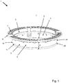
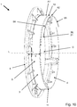
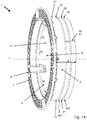
- the Fig. 1 to 3 each show in a perspective view a manhole cover frame 1 for a manhole cover arrangement (80, cf. Fig. 17 ) for use in road construction and rehabilitation. This forms a running in a longitudinal direction L shaft passage D.
- the manhole cover frame 1 On the upper side, the manhole cover frame 1 has a closure element receptacle 2 for receiving a closure element (81, cf. Fig. 17 ) of a manhole cover assembly (80, cf. Fig. 17 ) with which the shaft passage D can be closed.
- the closure element receptacle 2 is bordered radially by a frame collar 6, which forms an upper-side traffic area 7.
- the frame collar 6 projects radially beyond the frame skirt 3.
- the shaft passage D extends through both this frame skirt 3 and the closure element receptacle 2 and the frame collar. 6
- the manhole cover frame 1 is formed in one piece from cast iron, in particular including the closure element receptacle 2, the frame collar 6 and the frame skirt 3.
- the frame skirt 3 has a first predetermined breaking point 10 which extends transversely to the longitudinal direction L, and the frame skirt 3 in a first portion A1, which adjoins the closure element receptacle 2, and a breakable second portion A2 divided.
- the first Predetermined breaking point 10 is formed as a predetermined breaking groove 11 on the outside 5 of the frame skirt 3, which runs along the entire circumference of the frame skirt 3.
- the frame skirt 3 has a wall thickness W and the predetermined breaking groove 11 has a groove depth T1 which is at least 25%, and preferably at least 30%, of the wall thickness W of the frame skirt 3 in the region of the predetermined breaking groove 11.
- this groove depth T1 should be at most 60%, and preferably at most 50%, of the wall thickness W of the frame skirt 3 in the region of the predetermined breaking groove 11.
- the predetermined breaking groove 11 has a roundish groove cross section.
- the longitudinal section after Fig. 4 shows in particular a section through a manhole cover frame 1 after the Fig. 2 or 3 Therefore, reference is made to the description thereof with regard to the further construction of the manhole cover frame 1.
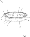
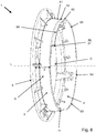
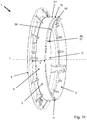
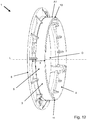
- Fig. 2 deviates in this respect from the execution Fig. 1 that the frangible second portion A2 of the frame skirt 3 has a single segmentation breakpoint 30 extending in the longitudinal direction L and the second portion A2 in the circumferential direction of the frame skirt 3, in particular such that the second portion A2 as an open ring or in circumferential segments ( S1, S2, S3, S4, S5, S6, cf. 6 to 12 ) is breakable, in particular irreversible by fracture separation or cancel. Deviating from this are in the embodiment according to Fig. 3 a plurality of segmentation break points 30 evenly distributed over the circumference of the second portion A2 arranged distributed.
- the segmentation break points 30 after the Fig. 2 and 3 each extend over the entire length between the first predetermined breaking point 10 and the end of the frame skirt 3, which faces away from the closure element receptacle 2.
- the Segment michssollbruchstellen 30 are each in a common plane with the longitudinal direction L or perpendicular to the first predetermined breaking point 10.
- the Segment michssollbruchstellen 30 are each formed as a predetermined breaking groove 31 on the outer side 5 of the frame skirt 3.
- the predetermined breaking groove 31 of the segmentation break points 30 has a groove depth T3 which is at least 25%, and preferably at least 30%, of the wall thickness W of the frame skirt 3 in the region of the predetermined breaking groove 31.
- this groove depth T3 of the predetermined breaking groove 31 of the segmentation break points 30 should be at most 60%, and preferably at most 50%, of the wall thickness W of the frame skirt 3 in the region of Sollbruchnut 31 amount.
- Visible also has the predetermined breaking groove 31 of the segmentation break points 30 each have a roundish groove cross-section.
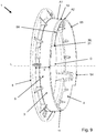
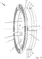
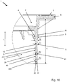
- the chess cover frames according to Fig. 13 . 14 and 15 correspond in this order essentially to those in the Fig. 1 . 2 and 3 are shown, therefore, reference is first made to their description.
- Main difference is in each case that the frame skirt 3 has a second predetermined breaking point 20 which extends transversely to the longitudinal direction L and divides the breakable second portion A2 of the frame skirt 3 into a breakable first portion A21 and a breakable further portion A22.
- the length X of the frame skirt 3 can be shortened to two different values, in particular irreversibly by breaking off one or both partial sections A21, A22.
- the second predetermined breaking point 20 lies between the first predetermined breaking point 10 and the end of the frame skirt 3, which faces away from the closure element receptacle 2.
- the second predetermined breaking point 20 breaks lighter than the first predetermined breaking point 10.
- the second predetermined breaking point 20 is formed as a predetermined breaking groove 21 on the outside 5 of the frame skirt 3 along the entire Scope of the frame skirt 3 runs.
- the predetermined breaking groove 21 of the second predetermined breaking point 20 has a rounded groove cross section.
- the predetermined breaking groove 21 of the second predetermined breaking point 20 has a groove depth T2 which amounts to at least 25%, and preferably at least 30%, of the wall thickness W of the frame skirt 3 in the region of the predetermined breaking groove 21.
- the wall thickness W decreases with increasing distance from the closure element receptacle 2.
- the groove depth T2 of Sollbruchnut 21 of the second predetermined breaking point 20 should, however, be at most 60%, and preferably at most 50%, of the wall thickness W of the frame skirt 3 in the region of this predetermined breaking groove 11. Furthermore, it can be seen that the first predetermined breaking point 10 is slightly weaker than the segmentation breakpoint 30 in the adjacent region. Similarly, the second predetermined breaking point 20 is slightly weaker than the segmentation breakpoint 30 in the adjacent area. This promotes a straight crack formation along the first and / or second predetermined breaking point 10, 20.
- Fig. 13 . 14 . 15 and 16 each show that the least one segmentation breakpoint 30 extends over the entire length of the second portion A2, thus aligned over the first and the second portion A21, A22, in the longitudinal direction L.
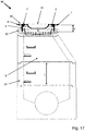
- Fig. 17 a longitudinal section through a shaft assembly 90 with a manhole cover assembly 80 on a shaft assembly 91 is shown.
- the manhole cover assembly 80 includes a manhole cover frame 1 which may be used, for example, as shown in FIGS Fig. 1 to 16 can be designed.
- a shutter member 81 of the tray cover assembly 80 is inserted into the shutter member receiver 2 of the tray cover frame 1, thereby closing the tray passage D.
- the manhole cover frame 1 faces the manhole structure 91 with the frame skirt 3, and would, if lowered completely, sit on the manhole structure 91 and rest on it. This is particularly the case because the frame skirt 3 is longitudinally displaceable in a guide of a centering ring 92 of the shaft assembly 91, whose diameter is greater than the actual diameter of the shaft assembly 91 at its upper end. The outer diameter of the frame skirt 3 is therefore greater than the diameter of the shaft structure 91 below the centering ring 92.
- the manhole cover frame 1 For installation of the manhole cover frame 1, it is now possible to first determine how high the available construction height for the manhole cover frame 1 is between the upper end of the manhole structure 91 and the desired installation height of the closure element receptacle 2 or traffic area 7. Subsequently, the manhole cover frame 1 is installed either without shortening the frame skirt 3, if the available construction height is greater than a defined limit. Alternatively, the installation is carried out only after a shortening of the frame skirt 3 in the longitudinal direction L by at least partially Canceling of the second section A2 at a predetermined breaking point 10, 20, if the available construction height is less than the defined limit value. For this purpose, for example, be hit with a hammer on the outside 5 of the second section A2 (see Fig. 1 to 16 ).
Landscapes
- Engineering & Computer Science (AREA)
- Environmental & Geological Engineering (AREA)
- Life Sciences & Earth Sciences (AREA)
- General Life Sciences & Earth Sciences (AREA)
- Mining & Mineral Resources (AREA)
- Paleontology (AREA)
- Civil Engineering (AREA)
- General Engineering & Computer Science (AREA)
- Structural Engineering (AREA)
- Underground Structures, Protecting, Testing And Restoring Foundations (AREA)
Applications Claiming Priority (1)
| Application Number | Priority Date | Filing Date | Title |
|---|---|---|---|
| DE102018109220.2A DE102018109220A1 (de) | 2018-04-18 | 2018-04-18 | Schachtabdeckungsrahmen, Schachtabdeckungsanordnung, Schachtanordnung und Installationsverfahren |
Publications (2)
| Publication Number | Publication Date |
|---|---|
| EP3556944A1 true EP3556944A1 (fr) | 2019-10-23 |
| EP3556944B1 EP3556944B1 (fr) | 2024-05-01 |
Family
ID=65904196
Family Applications (1)
| Application Number | Title | Priority Date | Filing Date |
|---|---|---|---|
| EP19164383.2A Active EP3556944B1 (fr) | 2018-04-18 | 2019-03-21 | Cadre de couverture de puits, dispositif de couverture de puits, dispositif de puits et procédé d'installation |
Country Status (3)
| Country | Link |
|---|---|
| EP (1) | EP3556944B1 (fr) |
| DE (2) | DE102018109220A1 (fr) |
| PL (1) | PL3556944T3 (fr) |
Cited By (1)
| Publication number | Priority date | Publication date | Assignee | Title |
|---|---|---|---|---|
| CN115110911A (zh) * | 2022-07-14 | 2022-09-27 | 田爽 | 一种井口对接装置及其对接方法 |
Citations (4)
| Publication number | Priority date | Publication date | Assignee | Title |
|---|---|---|---|---|
| DE9215759U1 (de) * | 1992-11-20 | 1993-03-04 | Passavant-Werke AG, 6209 Aarbergen | Aus Rahmen und klappbarem Deckel oder Rost bestehender Kanalisationsartikel |
| EP0953687A2 (fr) * | 1998-04-30 | 1999-11-03 | Gerhard Schone | Dispositif de mise à niveau entre un regard de chaussée et la surface d'une chaussée |
| EP2317197A1 (fr) * | 2009-11-02 | 2011-05-04 | R. Nussbaum AG | Tuyau indéformable pour le guidage d'eau |
| DE102015106750A1 (de) * | 2015-04-30 | 2016-11-03 | ACO Severin Ahlmann GmbH & Co Kommanditgesellschaft | Schachtabdeckung |
Family Cites Families (2)
| Publication number | Priority date | Publication date | Assignee | Title |
|---|---|---|---|---|
| US6311433B1 (en) | 2000-09-05 | 2001-11-06 | David J. Zdroik | Adjustable manhole/catch basin structure |
| DE102006056146B4 (de) * | 2006-11-28 | 2021-04-01 | Aco Severin Ahlmann Gmbh & Co. Kg | Reinigungsrohr zum Einbau in eine Rohrleitung unter einer Bodenplatte |
-
2018
- 2018-04-18 DE DE102018109220.2A patent/DE102018109220A1/de not_active Withdrawn
-
2019
- 2019-03-21 EP EP19164383.2A patent/EP3556944B1/fr active Active
- 2019-03-21 PL PL19164383.2T patent/PL3556944T3/pl unknown
- 2019-03-21 DE DE202019005915.6U patent/DE202019005915U1/de active Active
Patent Citations (4)
| Publication number | Priority date | Publication date | Assignee | Title |
|---|---|---|---|---|
| DE9215759U1 (de) * | 1992-11-20 | 1993-03-04 | Passavant-Werke AG, 6209 Aarbergen | Aus Rahmen und klappbarem Deckel oder Rost bestehender Kanalisationsartikel |
| EP0953687A2 (fr) * | 1998-04-30 | 1999-11-03 | Gerhard Schone | Dispositif de mise à niveau entre un regard de chaussée et la surface d'une chaussée |
| EP2317197A1 (fr) * | 2009-11-02 | 2011-05-04 | R. Nussbaum AG | Tuyau indéformable pour le guidage d'eau |
| DE102015106750A1 (de) * | 2015-04-30 | 2016-11-03 | ACO Severin Ahlmann GmbH & Co Kommanditgesellschaft | Schachtabdeckung |
Cited By (2)
| Publication number | Priority date | Publication date | Assignee | Title |
|---|---|---|---|---|
| CN115110911A (zh) * | 2022-07-14 | 2022-09-27 | 田爽 | 一种井口对接装置及其对接方法 |
| CN115110911B (zh) * | 2022-07-14 | 2024-05-14 | 东营大明石油工程科技开发有限责任公司 | 一种井口对接装置及其对接方法 |
Also Published As
| Publication number | Publication date |
|---|---|
| EP3556944B1 (fr) | 2024-05-01 |
| PL3556944T3 (pl) | 2024-10-28 |
| DE202019005915U1 (de) | 2023-04-05 |
| DE102018109220A1 (de) | 2019-10-24 |
Similar Documents
| Publication | Publication Date | Title |
|---|---|---|
| DE102010015404B4 (de) | Verfahren zur Reparatur einer Rotoranordnung einer Turbomaschine, Ringelement für eine Rotoranordnung einer Turbomaschine sowie Rotoranordnung für eine Turbomaschine | |
| EP2839083B9 (fr) | Pointe d'un pieu | |
| EP0173227B1 (fr) | Elément d'ancrage pour la fixation d'échelons dans des parois | |
| DE3033909C2 (de) | Verbindungselement | |
| EP0426951A2 (fr) | Barre d'ancrage | |
| EP1045087B1 (fr) | Point d'accrochage protégé de la corrosion | |
| EP3023185A2 (fr) | Outil entraîné en rotation autour d'un axe de rotation ou d'oscillation comprenant un profil d'entraînement destiné a s'accoupler à un profil d'entraînement | |
| EP3556944A1 (fr) | Cadre de couverture de puits, dispositif de couverture de puits, dispositif de puits et procédé d'installation | |
| DE102011081443A1 (de) | Bohrkrone, insbesondere Stahlbetonbohrkrone | |
| DE19651176B4 (de) | Lösbare axiale Sicherung | |
| EP0262444A1 (fr) | Dispositif d'ancrage, notamment cheville | |
| DE102016123316B4 (de) | Werkzeug zum Schneiden eines Gewindes | |
| DE2652630A1 (de) | Duebelanker | |
| EP2959995B1 (fr) | Outil de montage et procédé d'installation en retrait d'une rosace de cheville | |
| EP3508667B1 (fr) | Procédé de raccordement d'un écarteur avec un fer de raccord, dispositif support d'écarteur et support de butée, cale et support | |
| DE102015119962A1 (de) | Um eine Oszillations- oder Drehachse drehantreibbares Werkzeug mit einem Antriebsprofil zur Kupplung mit einem Abtriebsprofil | |
| CH711156B1 (de) | Anschlagelement, Positioniervorrichtung mit mindestens einem solchen Anschlagelement und Verfahren zur Positionierung von Wandschalungen. | |
| EP4116539B1 (fr) | Tête de perçage d'une tarière, procédé de fabrication d'une tête de perçage d'une tarière et utilisation d'une tête de perçage d'une tarière | |
| DE2855284A1 (de) | Einrichtung zur befestigung von arbeitswerkzeugen mit schlagwirkung | |
| EP2634439B1 (fr) | Douille perforée pour une cheville | |
| DE2343836B2 (de) | Endstueck zum schutz der enden von rohren gegen beschaedigungen | |
| EP3296045A1 (fr) | Foret | |
| DE9218843U1 (de) | Absenkvorrichtung für lasttragende Systemteile | |
| WO1994010419A1 (fr) | Dispositif permettant de fixer un cadre grillage | |
| DE102015206223B4 (de) | Wälzlagerkäfig |
Legal Events
| Date | Code | Title | Description |
|---|---|---|---|
| PUAI | Public reference made under article 153(3) epc to a published international application that has entered the european phase |
Free format text: ORIGINAL CODE: 0009012 |
|
| STAA | Information on the status of an ep patent application or granted ep patent |
Free format text: STATUS: THE APPLICATION HAS BEEN PUBLISHED |
|
| AK | Designated contracting states |
Kind code of ref document: A1 Designated state(s): AL AT BE BG CH CY CZ DE DK EE ES FI FR GB GR HR HU IE IS IT LI LT LU LV MC MK MT NL NO PL PT RO RS SE SI SK SM TR |
|
| AX | Request for extension of the european patent |
Extension state: BA ME |
|
| STAA | Information on the status of an ep patent application or granted ep patent |
Free format text: STATUS: REQUEST FOR EXAMINATION WAS MADE |
|
| 17P | Request for examination filed |
Effective date: 20200410 |
|
| RBV | Designated contracting states (corrected) |
Designated state(s): AL AT BE BG CH CY CZ DE DK EE ES FI FR GB GR HR HU IE IS IT LI LT LU LV MC MK MT NL NO PL PT RO RS SE SI SK SM TR |
|
| STAA | Information on the status of an ep patent application or granted ep patent |
Free format text: STATUS: EXAMINATION IS IN PROGRESS |
|
| 17Q | First examination report despatched |
Effective date: 20211012 |
|
| GRAP | Despatch of communication of intention to grant a patent |
Free format text: ORIGINAL CODE: EPIDOSNIGR1 |
|
| STAA | Information on the status of an ep patent application or granted ep patent |
Free format text: STATUS: GRANT OF PATENT IS INTENDED |
|
| INTG | Intention to grant announced |
Effective date: 20240112 |
|
| GRAS | Grant fee paid |
Free format text: ORIGINAL CODE: EPIDOSNIGR3 |
|
| GRAA | (expected) grant |
Free format text: ORIGINAL CODE: 0009210 |
|
| STAA | Information on the status of an ep patent application or granted ep patent |
Free format text: STATUS: THE PATENT HAS BEEN GRANTED |
|
| AK | Designated contracting states |
Kind code of ref document: B1 Designated state(s): AL AT BE BG CH CY CZ DE DK EE ES FI FR GB GR HR HU IE IS IT LI LT LU LV MC MK MT NL NO PL PT RO RS SE SI SK SM TR |
|
| REG | Reference to a national code |
Ref country code: GB Ref legal event code: FG4D Free format text: NOT ENGLISH |
|
| REG | Reference to a national code |
Ref country code: CH Ref legal event code: EP |
|
| REG | Reference to a national code |
Ref country code: DE Ref legal event code: R096 Ref document number: 502019011155 Country of ref document: DE |
|
| REG | Reference to a national code |
Ref country code: IE Ref legal event code: FG4D Free format text: LANGUAGE OF EP DOCUMENT: GERMAN |
|
| REG | Reference to a national code |
Ref country code: NL Ref legal event code: FP |
|
| REG | Reference to a national code |
Ref country code: LT Ref legal event code: MG9D |
|
| PG25 | Lapsed in a contracting state [announced via postgrant information from national office to epo] |
Ref country code: IS Free format text: LAPSE BECAUSE OF FAILURE TO SUBMIT A TRANSLATION OF THE DESCRIPTION OR TO PAY THE FEE WITHIN THE PRESCRIBED TIME-LIMIT Effective date: 20240901 |
|
| PG25 | Lapsed in a contracting state [announced via postgrant information from national office to epo] |
Ref country code: BG Free format text: LAPSE BECAUSE OF FAILURE TO SUBMIT A TRANSLATION OF THE DESCRIPTION OR TO PAY THE FEE WITHIN THE PRESCRIBED TIME-LIMIT Effective date: 20240501 |
|
| PG25 | Lapsed in a contracting state [announced via postgrant information from national office to epo] |
Ref country code: HR Free format text: LAPSE BECAUSE OF FAILURE TO SUBMIT A TRANSLATION OF THE DESCRIPTION OR TO PAY THE FEE WITHIN THE PRESCRIBED TIME-LIMIT Effective date: 20240501 Ref country code: FI Free format text: LAPSE BECAUSE OF FAILURE TO SUBMIT A TRANSLATION OF THE DESCRIPTION OR TO PAY THE FEE WITHIN THE PRESCRIBED TIME-LIMIT Effective date: 20240501 |
|
| PG25 | Lapsed in a contracting state [announced via postgrant information from national office to epo] |
Ref country code: GR Free format text: LAPSE BECAUSE OF FAILURE TO SUBMIT A TRANSLATION OF THE DESCRIPTION OR TO PAY THE FEE WITHIN THE PRESCRIBED TIME-LIMIT Effective date: 20240802 |
|
| PG25 | Lapsed in a contracting state [announced via postgrant information from national office to epo] |
Ref country code: PT Free format text: LAPSE BECAUSE OF FAILURE TO SUBMIT A TRANSLATION OF THE DESCRIPTION OR TO PAY THE FEE WITHIN THE PRESCRIBED TIME-LIMIT Effective date: 20240902 |
|
| PG25 | Lapsed in a contracting state [announced via postgrant information from national office to epo] |
Ref country code: ES Free format text: LAPSE BECAUSE OF FAILURE TO SUBMIT A TRANSLATION OF THE DESCRIPTION OR TO PAY THE FEE WITHIN THE PRESCRIBED TIME-LIMIT Effective date: 20240501 |
|
| PG25 | Lapsed in a contracting state [announced via postgrant information from national office to epo] |
Ref country code: PT Free format text: LAPSE BECAUSE OF FAILURE TO SUBMIT A TRANSLATION OF THE DESCRIPTION OR TO PAY THE FEE WITHIN THE PRESCRIBED TIME-LIMIT Effective date: 20240902 Ref country code: NO Free format text: LAPSE BECAUSE OF FAILURE TO SUBMIT A TRANSLATION OF THE DESCRIPTION OR TO PAY THE FEE WITHIN THE PRESCRIBED TIME-LIMIT Effective date: 20240801 Ref country code: IS Free format text: LAPSE BECAUSE OF FAILURE TO SUBMIT A TRANSLATION OF THE DESCRIPTION OR TO PAY THE FEE WITHIN THE PRESCRIBED TIME-LIMIT Effective date: 20240901 Ref country code: HR Free format text: LAPSE BECAUSE OF FAILURE TO SUBMIT A TRANSLATION OF THE DESCRIPTION OR TO PAY THE FEE WITHIN THE PRESCRIBED TIME-LIMIT Effective date: 20240501 Ref country code: GR Free format text: LAPSE BECAUSE OF FAILURE TO SUBMIT A TRANSLATION OF THE DESCRIPTION OR TO PAY THE FEE WITHIN THE PRESCRIBED TIME-LIMIT Effective date: 20240802 Ref country code: FI Free format text: LAPSE BECAUSE OF FAILURE TO SUBMIT A TRANSLATION OF THE DESCRIPTION OR TO PAY THE FEE WITHIN THE PRESCRIBED TIME-LIMIT Effective date: 20240501 Ref country code: ES Free format text: LAPSE BECAUSE OF FAILURE TO SUBMIT A TRANSLATION OF THE DESCRIPTION OR TO PAY THE FEE WITHIN THE PRESCRIBED TIME-LIMIT Effective date: 20240501 Ref country code: BG Free format text: LAPSE BECAUSE OF FAILURE TO SUBMIT A TRANSLATION OF THE DESCRIPTION OR TO PAY THE FEE WITHIN THE PRESCRIBED TIME-LIMIT Effective date: 20240501 Ref country code: RS Free format text: LAPSE BECAUSE OF FAILURE TO SUBMIT A TRANSLATION OF THE DESCRIPTION OR TO PAY THE FEE WITHIN THE PRESCRIBED TIME-LIMIT Effective date: 20240801 |
|
| PG25 | Lapsed in a contracting state [announced via postgrant information from national office to epo] |
Ref country code: DK Free format text: LAPSE BECAUSE OF FAILURE TO SUBMIT A TRANSLATION OF THE DESCRIPTION OR TO PAY THE FEE WITHIN THE PRESCRIBED TIME-LIMIT Effective date: 20240501 |
|
| PG25 | Lapsed in a contracting state [announced via postgrant information from national office to epo] |
Ref country code: EE Free format text: LAPSE BECAUSE OF FAILURE TO SUBMIT A TRANSLATION OF THE DESCRIPTION OR TO PAY THE FEE WITHIN THE PRESCRIBED TIME-LIMIT Effective date: 20240501 |
|
| PG25 | Lapsed in a contracting state [announced via postgrant information from national office to epo] |
Ref country code: RO Free format text: LAPSE BECAUSE OF FAILURE TO SUBMIT A TRANSLATION OF THE DESCRIPTION OR TO PAY THE FEE WITHIN THE PRESCRIBED TIME-LIMIT Effective date: 20240501 Ref country code: SK Free format text: LAPSE BECAUSE OF FAILURE TO SUBMIT A TRANSLATION OF THE DESCRIPTION OR TO PAY THE FEE WITHIN THE PRESCRIBED TIME-LIMIT Effective date: 20240501 |
|
| PG25 | Lapsed in a contracting state [announced via postgrant information from national office to epo] |
Ref country code: SM Free format text: LAPSE BECAUSE OF FAILURE TO SUBMIT A TRANSLATION OF THE DESCRIPTION OR TO PAY THE FEE WITHIN THE PRESCRIBED TIME-LIMIT Effective date: 20240501 |
|
| PG25 | Lapsed in a contracting state [announced via postgrant information from national office to epo] |
Ref country code: SM Free format text: LAPSE BECAUSE OF FAILURE TO SUBMIT A TRANSLATION OF THE DESCRIPTION OR TO PAY THE FEE WITHIN THE PRESCRIBED TIME-LIMIT Effective date: 20240501 Ref country code: SK Free format text: LAPSE BECAUSE OF FAILURE TO SUBMIT A TRANSLATION OF THE DESCRIPTION OR TO PAY THE FEE WITHIN THE PRESCRIBED TIME-LIMIT Effective date: 20240501 Ref country code: RO Free format text: LAPSE BECAUSE OF FAILURE TO SUBMIT A TRANSLATION OF THE DESCRIPTION OR TO PAY THE FEE WITHIN THE PRESCRIBED TIME-LIMIT Effective date: 20240501 Ref country code: EE Free format text: LAPSE BECAUSE OF FAILURE TO SUBMIT A TRANSLATION OF THE DESCRIPTION OR TO PAY THE FEE WITHIN THE PRESCRIBED TIME-LIMIT Effective date: 20240501 Ref country code: DK Free format text: LAPSE BECAUSE OF FAILURE TO SUBMIT A TRANSLATION OF THE DESCRIPTION OR TO PAY THE FEE WITHIN THE PRESCRIBED TIME-LIMIT Effective date: 20240501 |
|
| REG | Reference to a national code |
Ref country code: DE Ref legal event code: R097 Ref document number: 502019011155 Country of ref document: DE |
|
| PG25 | Lapsed in a contracting state [announced via postgrant information from national office to epo] |
Ref country code: IT Free format text: LAPSE BECAUSE OF FAILURE TO SUBMIT A TRANSLATION OF THE DESCRIPTION OR TO PAY THE FEE WITHIN THE PRESCRIBED TIME-LIMIT Effective date: 20240501 |
|
| PLBE | No opposition filed within time limit |
Free format text: ORIGINAL CODE: 0009261 |
|
| STAA | Information on the status of an ep patent application or granted ep patent |
Free format text: STATUS: NO OPPOSITION FILED WITHIN TIME LIMIT |
|
| 26N | No opposition filed |
Effective date: 20250204 |
|
| PGFP | Annual fee paid to national office [announced via postgrant information from national office to epo] |
Ref country code: DE Payment date: 20250331 Year of fee payment: 7 |
|
| PGFP | Annual fee paid to national office [announced via postgrant information from national office to epo] |
Ref country code: NL Payment date: 20250319 Year of fee payment: 7 |
|
| PGFP | Annual fee paid to national office [announced via postgrant information from national office to epo] |
Ref country code: LU Payment date: 20250320 Year of fee payment: 7 |
|
| PG25 | Lapsed in a contracting state [announced via postgrant information from national office to epo] |
Ref country code: SI Free format text: LAPSE BECAUSE OF FAILURE TO SUBMIT A TRANSLATION OF THE DESCRIPTION OR TO PAY THE FEE WITHIN THE PRESCRIBED TIME-LIMIT Effective date: 20240501 |
|
| PGFP | Annual fee paid to national office [announced via postgrant information from national office to epo] |
Ref country code: AT Payment date: 20250320 Year of fee payment: 7 Ref country code: LV Payment date: 20250320 Year of fee payment: 7 |
|
| PGFP | Annual fee paid to national office [announced via postgrant information from national office to epo] |
Ref country code: PL Payment date: 20250317 Year of fee payment: 7 Ref country code: CZ Payment date: 20250317 Year of fee payment: 7 |
|
| PGFP | Annual fee paid to national office [announced via postgrant information from national office to epo] |
Ref country code: CH Payment date: 20250401 Year of fee payment: 7 |
|
| PG25 | Lapsed in a contracting state [announced via postgrant information from national office to epo] |
Ref country code: SE Free format text: LAPSE BECAUSE OF FAILURE TO SUBMIT A TRANSLATION OF THE DESCRIPTION OR TO PAY THE FEE WITHIN THE PRESCRIBED TIME-LIMIT Effective date: 20240501 |
|
| PG25 | Lapsed in a contracting state [announced via postgrant information from national office to epo] |
Ref country code: MC Free format text: LAPSE BECAUSE OF FAILURE TO SUBMIT A TRANSLATION OF THE DESCRIPTION OR TO PAY THE FEE WITHIN THE PRESCRIBED TIME-LIMIT Effective date: 20240501 |
|
| GBPC | Gb: european patent ceased through non-payment of renewal fee |
Effective date: 20250321 |
|
| REG | Reference to a national code |
Ref country code: BE Ref legal event code: MM Effective date: 20250331 |
|
| PG25 | Lapsed in a contracting state [announced via postgrant information from national office to epo] |
Ref country code: GB Free format text: LAPSE BECAUSE OF NON-PAYMENT OF DUE FEES Effective date: 20250321 |
|
| PG25 | Lapsed in a contracting state [announced via postgrant information from national office to epo] |
Ref country code: FR Free format text: LAPSE BECAUSE OF NON-PAYMENT OF DUE FEES Effective date: 20250331 |
|
| PG25 | Lapsed in a contracting state [announced via postgrant information from national office to epo] |
Ref country code: BE Free format text: LAPSE BECAUSE OF NON-PAYMENT OF DUE FEES Effective date: 20250331 |
|
| PG25 | Lapsed in a contracting state [announced via postgrant information from national office to epo] |
Ref country code: IE Free format text: LAPSE BECAUSE OF NON-PAYMENT OF DUE FEES Effective date: 20250321 |