EP3556903A1 - System und verfahren zur schnellen impulsgaszufuhr - Google Patents
System und verfahren zur schnellen impulsgaszufuhr Download PDFInfo
- Publication number
- EP3556903A1 EP3556903A1 EP19161633.3A EP19161633A EP3556903A1 EP 3556903 A1 EP3556903 A1 EP 3556903A1 EP 19161633 A EP19161633 A EP 19161633A EP 3556903 A1 EP3556903 A1 EP 3556903A1
- Authority
- EP
- European Patent Office
- Prior art keywords
- mass flow
- flow controller
- gas
- pulse
- delivery
- Prior art date
- Legal status (The legal status is an assumption and is not a legal conclusion. Google has not performed a legal analysis and makes no representation as to the accuracy of the status listed.)
- Granted
Links
Images




Classifications
-
- C—CHEMISTRY; METALLURGY
- C23—COATING METALLIC MATERIAL; COATING MATERIAL WITH METALLIC MATERIAL; CHEMICAL SURFACE TREATMENT; DIFFUSION TREATMENT OF METALLIC MATERIAL; COATING BY VACUUM EVAPORATION, BY SPUTTERING, BY ION IMPLANTATION OR BY CHEMICAL VAPOUR DEPOSITION, IN GENERAL; INHIBITING CORROSION OF METALLIC MATERIAL OR INCRUSTATION IN GENERAL
- C23C—COATING METALLIC MATERIAL; COATING MATERIAL WITH METALLIC MATERIAL; SURFACE TREATMENT OF METALLIC MATERIAL BY DIFFUSION INTO THE SURFACE, BY CHEMICAL CONVERSION OR SUBSTITUTION; COATING BY VACUUM EVAPORATION, BY SPUTTERING, BY ION IMPLANTATION OR BY CHEMICAL VAPOUR DEPOSITION, IN GENERAL
- C23C16/00—Chemical coating by decomposition of gaseous compounds, without leaving reaction products of surface material in the coating, i.e. chemical vapour deposition [CVD] processes
- C23C16/44—Chemical coating by decomposition of gaseous compounds, without leaving reaction products of surface material in the coating, i.e. chemical vapour deposition [CVD] processes characterised by the method of coating
- C23C16/52—Controlling or regulating the coating process
-
- C—CHEMISTRY; METALLURGY
- C23—COATING METALLIC MATERIAL; COATING MATERIAL WITH METALLIC MATERIAL; CHEMICAL SURFACE TREATMENT; DIFFUSION TREATMENT OF METALLIC MATERIAL; COATING BY VACUUM EVAPORATION, BY SPUTTERING, BY ION IMPLANTATION OR BY CHEMICAL VAPOUR DEPOSITION, IN GENERAL; INHIBITING CORROSION OF METALLIC MATERIAL OR INCRUSTATION IN GENERAL
- C23C—COATING METALLIC MATERIAL; COATING MATERIAL WITH METALLIC MATERIAL; SURFACE TREATMENT OF METALLIC MATERIAL BY DIFFUSION INTO THE SURFACE, BY CHEMICAL CONVERSION OR SUBSTITUTION; COATING BY VACUUM EVAPORATION, BY SPUTTERING, BY ION IMPLANTATION OR BY CHEMICAL VAPOUR DEPOSITION, IN GENERAL
- C23C16/00—Chemical coating by decomposition of gaseous compounds, without leaving reaction products of surface material in the coating, i.e. chemical vapour deposition [CVD] processes
- C23C16/44—Chemical coating by decomposition of gaseous compounds, without leaving reaction products of surface material in the coating, i.e. chemical vapour deposition [CVD] processes characterised by the method of coating
- C23C16/455—Chemical coating by decomposition of gaseous compounds, without leaving reaction products of surface material in the coating, i.e. chemical vapour deposition [CVD] processes characterised by the method of coating characterised by the method used for introducing gases into reaction chamber or for modifying gas flows in reaction chamber
- C23C16/45523—Pulsed gas flow or change of composition over time
-
- C—CHEMISTRY; METALLURGY
- C23—COATING METALLIC MATERIAL; COATING MATERIAL WITH METALLIC MATERIAL; CHEMICAL SURFACE TREATMENT; DIFFUSION TREATMENT OF METALLIC MATERIAL; COATING BY VACUUM EVAPORATION, BY SPUTTERING, BY ION IMPLANTATION OR BY CHEMICAL VAPOUR DEPOSITION, IN GENERAL; INHIBITING CORROSION OF METALLIC MATERIAL OR INCRUSTATION IN GENERAL
- C23C—COATING METALLIC MATERIAL; COATING MATERIAL WITH METALLIC MATERIAL; SURFACE TREATMENT OF METALLIC MATERIAL BY DIFFUSION INTO THE SURFACE, BY CHEMICAL CONVERSION OR SUBSTITUTION; COATING BY VACUUM EVAPORATION, BY SPUTTERING, BY ION IMPLANTATION OR BY CHEMICAL VAPOUR DEPOSITION, IN GENERAL
- C23C16/00—Chemical coating by decomposition of gaseous compounds, without leaving reaction products of surface material in the coating, i.e. chemical vapour deposition [CVD] processes
- C23C16/44—Chemical coating by decomposition of gaseous compounds, without leaving reaction products of surface material in the coating, i.e. chemical vapour deposition [CVD] processes characterised by the method of coating
- C23C16/455—Chemical coating by decomposition of gaseous compounds, without leaving reaction products of surface material in the coating, i.e. chemical vapour deposition [CVD] processes characterised by the method of coating characterised by the method used for introducing gases into reaction chamber or for modifying gas flows in reaction chamber
- C23C16/45561—Gas plumbing upstream of the reaction chamber
-
- G—PHYSICS
- G05—CONTROLLING; REGULATING
- G05D—SYSTEMS FOR CONTROLLING OR REGULATING NON-ELECTRIC VARIABLES
- G05D7/00—Control of flow
- G05D7/06—Control of flow characterised by the use of electric means
- G05D7/0617—Control of flow characterised by the use of electric means specially adapted for fluid materials
- G05D7/0629—Control of flow characterised by the use of electric means specially adapted for fluid materials characterised by the type of regulator means
- G05D7/0635—Control of flow characterised by the use of electric means specially adapted for fluid materials characterised by the type of regulator means by action on throttling means
-
- G—PHYSICS
- G05—CONTROLLING; REGULATING
- G05D—SYSTEMS FOR CONTROLLING OR REGULATING NON-ELECTRIC VARIABLES
- G05D7/00—Control of flow
- G05D7/06—Control of flow characterised by the use of electric means
- G05D7/0617—Control of flow characterised by the use of electric means specially adapted for fluid materials
- G05D7/0629—Control of flow characterised by the use of electric means specially adapted for fluid materials characterised by the type of regulator means
- G05D7/0635—Control of flow characterised by the use of electric means specially adapted for fluid materials characterised by the type of regulator means by action on throttling means
- G05D7/0641—Control of flow characterised by the use of electric means specially adapted for fluid materials characterised by the type of regulator means by action on throttling means using a plurality of throttling means
- G05D7/0647—Control of flow characterised by the use of electric means specially adapted for fluid materials characterised by the type of regulator means by action on throttling means using a plurality of throttling means the plurality of throttling means being arranged in series
Definitions
- Patent Application No. 13/035,534 entitled METHOD AND APPARATUS FOR MULTIPLE-CHANNEL PULSE GAS DELIVERY SYSTEM, filed February 25, 2011 in the name of Junhua Ding and assigned to the present assignee (Attorney's Docket No. 086400-0027 (MKS-219)), and U.S. Patent Application No. 13/193393 , entitled Systems and Methods of Controlling Time-Multiplexed Deep Reactive-Ion Etching Processes, filed July 28, 2011 in the name of Vladislav Davidkovich et al. and assigned to the present assignee (Attorney's Docket No. 086400-0059 (MKS-220)), all applications being incorporated herein in their entirety. All of these applications are referred to hereinafter as the "Copending Applications”.
- This disclosure relates generally to mole or gas delivery devices, and more particularly, to a method of and system for pulse gas delivery.
- gas(es) includes the term “vapor(s)” should the two terms be considered different.
- process tool may or may not include a process chamber.
- Various recipes are used in the manufacturing process, involving many discrete process steps, where a semiconductor device is typically cleaned, polished, oxidized, masked, etched, doped, metalized, etc. The steps used, their particular sequence, and the materials involved all contribute to the making of particular devices.
- ALD atomic layer deposition
- two or more precursor gases are delivered in pulses and flow over a wafer surface in a process tool maintained under vacuum.
- the two or more precursor gases flow in an alternating or sequential manner so that the gases can react with the sites or functional groups on the wafer surface.
- the reaction stops and a purge gas is used to purge the excess precursor molecules from the process tool.
- a cycle can be defined as one pulse of precursor A, purge, one pulse of precursor B, and purge.
- a cycle can include the pulses of additional precursor gases, as well as repeats of a precursor gas, with the use of a purge gas in between successive pulses of precursor gases. This sequence is repeated until a final geometric characteristic, such as thickness, is reached.
- the delivery of pulses of precursor gases introduced into a process tool can be controlled using a pulse gas delivery (PGD) device (the controlled flow of gas into and out of a delivery chamber using inlet and outlet on/off-type valves simply by timing the opening of the outlet shutoff valve for a predetermined period of time to deliver a desired amount (mass), in the form of a pulse, of precursor gas into the process chamber of the process tool).
- PPD pulse gas delivery
- MFC mass flow controller
- Pulse gas delivery (PGD) devices are usually pressure based and optimized to provide repeatable and precise quantities (mass) of gases for use in semiconductor manufacturing processes, such as ALD processes.
- current PGD devices include a delivery gas chamber 12, an inlet shut off valve 14 for controlling the flow of gas from a gas supply 52 into chamber 12, and an outlet shut off valve 16 for controlling the flow of gas from the delivery chamber 12 to the process tool 54.
- a host controller or computer 50 runs the gas delivery process as well as carries out all of the control and diagnostic functions for the process tool, including, for example, safety monitoring and control, RF power signals, and other common tasks.
- the amount of gas, measured in moles, introduced into the delivery chamber with each pulse is a function of the gas type, the temperature of the gas in the chamber, and the pressure drop of the gas during the duration of the pulse delivered from the chamber 12. Accordingly, pressure sensor 18 and temperature sensor 20 provide measurements of the pressure and temperature to the controller 24 so that the gas delivered from the chamber during each pulse can be determined.
- the control logic for running the PGD device has thus been traditionally and typically on the host controller 50 associated with the process tool. Improvements are described in the copending Applications by providing a dedicated controller 24 for separately controlling the pulse delivery process by operation of the inlet and outlet valves 14 and 16.
- TSVs thru-silicon vias
- Plasma etch technology such as the Bosch process, which has been used extensively for deep silicon etching in memory devices and MEMS production, is well suited for TSV creation.
- the Bosch process also known as a high speed pulsed or time-multiplexed etching, alternates repeatedly between two modes to achieve nearly vertical structures using SF 6 and the deposition of a chemically inert passivation layer using C 4 F 8 .
- Targets for TSV required for commercial success are adequate functionality, low cost, and proven reliability.
- Examples of pulse mass flow delivery systems can be found in U.S. Patent Nos. 7615120 ; 7615120 ; 7628860 ; 7628861 , 7662233 ; 7735452 and 7794544 ; U.S. Patent Publication Nos. 2006/0060139 ; and 2006/0130755 , and pending U.S. Application Serial Nos. 12/689,961 , entitled CONTROL FOR AND METHOD OF PULSED GAS DELIVERY, filed January 19, 2010 in the name of Paul Meneghini and assigned the present assignee (Attorney's Docket No. 56231-751 (MKS-194)); and U.S. Patent Application No.
- a programmable mass flow controller comprising: an input configured to receive an input signal and an output configured to provide an output signal.
- a communication port is configured to receive program instructions including instructions relating to the programmed configuration of the mass flow controller, and programming data.
- a flow sensor is configured to sense the flow of gas through the mass flow controller; and a control valve is configured to control the flow of gas though the mass flow controller.
- Memory is configured and arranged to receive programming data determining the programmed configuration of the mass flow controller as either a digital or analog configuration; and a processor/controller is providing to operate the mass flow controller in accordance with the programmed configuration.
- the programmed digital configuration enables the mass flow controller to respond to digital signals applied to the input.
- the programmed analog configuration enables the mass flow controller to respond to analog signals applied to the input.
- the communication port also is configured to receive data relating to parameters associated with at least one of two modes of operation of the mass flow controller.
- the at least one of two modes of operation of the mass flow controller includes a classic mass flow controller mode of operation, wherein the input signal represents the flow setpoint for operating the MFC in the classic mass flow controller mode of operation.
- the at least one of two modes of operation of the mass flow controller includes a pulse gas delivery mode of operation, wherein the input signal represents a pulse trigger signal for operating the MFC so as to deliver a sequence of pulses in the pulse gas delivery mode of operation.
- the communication port is configured to receive parameters for pulse gas delivery.
- the parameters are associated with a mole delivery mode of gas pulse delivery operation.
- the parameters include the pulse-on period, pulse-off period, the mole delivery setpoint, and the number of pulses.
- the mass flow controller further includes a digital communication interface that includes the digital communication port.
- the mass flow controller further includes an analog communication interface having an analog input pin for forming the input and receiving an analog trigger signal input, and an analog output pin for forming the output and providing an analog synchronization signal output.
- the mass flow controller further includes both a digital communication interface and an analog communication interface.
- the output signal represents a synchronization signal for use in synchronizing the timing of the delivery of a sequence of pulses with the operation of another device.
- the another device is a second mass flow controller.
- the synchronization signal is a trigger signal input to the second mass flow controller.
- the another device is an RF power generator.
- the another device is a pressure controller.
- the synchronization signal is generated prior to the completion of the delivery of the sequence of pulses. In one embodiment the synchronization signal is generated simultaneously with the completion of the delivery of the sequence of pulses. In one embodiment the synchronization signal is generated after the completion of the delivery of the sequence of pulses by a predetermined delay. In one embodiment the pulse trigger signal is a digital signal. In one embodiment the pulse trigger signal is an analog signal. In one embodiment the output signal is a TTL synchronization output signal for use by another device.
- a system comprises: a multi-channel gas delivery system including a plurality of flow channels, each channel comprising a mass flow controller configured to control the flow of gas through the corresponding channel.
- Each mass flow controller includes: an input configured to receive an input signal; an output configured to provide an output signal; a communication port configured to receive program instructions including instructions on the operational configuration of each mass flow controller; a flow sensor configured to sense the flow of gas through the mass flow controller of the corresponding channel; a control valve configured to control the flow of gas though the mass flow controller of the corresponding channel; memory configured and arranged to receive programming data determining the programmed configuration of the mass flow controller as either a digital or analog configuration; and a processor/controller for operating the mass flow controller in accordance with the programmed configuration.
- the input signal to the mass flow controller initiates the operation of the mass flow controller to deliver a prescribed amount of gas, and the output signal is generated as a function of the timing of the delivery so that the output signal can be used to synchronize each mass flow controller to at least one other device.
- the output signal of at least one mass flow controller is used as an input signal to initiate the operation of another one of the mass flow controllers of the multi-channel fast pulse gas delivery system to deliver a prescribed amount of gas so that the mass flow controllers define a daisy chain of devices sequentially providing the delivery of prescribed amounts of gas through the corresponding channels.
- the output signal of each of the mass flow controllers is used to provide control signals applied to an RF power generator. In one embodiment the output signal of each of the mass flow controllers is used to provide control signals applied to a pressure controller. In one embodiment the input and output signals are analog signals. In one embodiment the digital communication port of each mass flow controller is configured to receive data relating to parameters associated with at least one of two modes of operation of the mass flow controller. In one embodiment the at least one of two modes of operation of each mass flow controller includes a pulse gas delivery mode of operation, wherein the input signal represents a pulse trigger signal for operating the MFC so as to deliver a sequence of pulses in the pulse gas delivery mode of operation. In one embodiment the digital communication port is configured to receive parameters for pulse gas delivery.
- the parameters are associated with a mole delivery mode of gas pulse delivery operation. In one embodiment the parameters include the pulse-on period, pulse-off period, the mole delivery setpoint, and the number of pulses.
- the system further includes a digital communication interface that includes the digital communication port. In one embodiment the system further includes both a digital communication interface and an analog communication interface. In one embodiment the system further includes an analog communication interface having an analog input pin for forming the input and receiving an analog trigger signal input, and an analog output pin for forming the output and providing an analog synchronization signal output.
- the analog synchronization signal is generated prior to the completion of the delivery of the sequence of pulses. In one embodiment the analog synchronization signal is generated simultaneously with the completion of the delivery of the sequence of pulses. In one embodiment the analog synchronization signal is generated after the completion of the delivery of the sequence of pulses by a predetermined delay. In one embodiment the output signal is a TTL synchronization output signal for use by another device.
- a method of operating a mass flow controller of the type comprising at least one communication port comprises: receiving, at the communication port, program instructions including instructions relating to the operational configuration of the mass flow controller as responsive to either digital or analog input signals; and operating the mass flow controller in accordance with the programmed configuration.
- a programmed digital operational configuration enables the mass flow controller to respond to digital signals applied to the input.
- a programmed analog operational configuration enables the mass flow controller to respond to analog signals applied to the input.
- receiving at the communication port program instructions includes receiving data relating to parameters associated with at least one of two modes of operation of the mass flow controller.
- at least one of two modes of operation of the mass flow controller includes a classic mass flow controller mode of operation, and the input signal represents the set point setting for operating the MFC in the classic mass flow controller mode of operation.
- at least one of two modes of operation of the mass flow controller includes a pulse gas delivery mode of operation, and further delivering a sequence of pulses in the pulse gas delivery mode of operation in response to an input signal.
- receiving instructions at the communication port program includes receiving parameters for pulse gas delivery.
- the parameters for pulse gas delivery are associated with a mole delivery mode of gas pulse delivery operation.
- the parameters include the pulse-on period, pulse-off period, the mole delivery setpoint, and the number of pulses.
- the method further includes receiving an analog trigger signal input at an analog input pin of an analog communication interface and providing an analog synchronization signal output at an analog output pin of the analog communication interface.
- the method further includes generating an output signal representing a synchronization signal for use in synchronizing the timing of the delivery of a sequence of pulses with the operation of another device.
- the another device is a second mass flow controller.
- the synchronization signal is a trigger signal for use as an input to the second mass flow controller.
- the another device is an RF power generator.
- the another device is a pressure controller.
- the method further includes generating the synchronization signal prior to the completion of the delivery of the sequence of pulses.
- the method further includes generating the synchronization signal simultaneously with the completion of the delivery of the sequence of pulses.
- the method further includes generating the synchronization signal by a predetermined delay after the completion of the delivery of the sequence of pulses.
- the trigger signal is generated as a digital signal.
- the trigger signal is generated as an analog signal.
- the output signal is a TTL synchronization output signal for use by another device.
- a method of operating a multi-channel gas delivery system including a plurality of flow channels comprises a mass flow controller configured to control the flow of gas through the corresponding channel.
- the method comprises: providing an input signal to one of the mass flow controllers so as to initiate the operation of the mass flow controller to deliver a prescribed amount of gas; generating an output signal from the mass flow controller as a function of the timing of the delivery of the prescribed amount of gas so that the output signal can be used to synchronize each mass flow controller to at least one other device; receiving program instructions at a communication port including instructions on the operational configuration of each mass flow controller; determining the programmed configuration of the mass flow controller as either a digital or analog configuration as a function of the received instructions; and operating the mass flow controller in accordance with the programmed configuration.
- the input signal to the mass flow controller initiates the operation of the mass flow controller to deliver a prescribed amount of gas, and the output signal is generated as a function of the timing of the delivery so that the output signal can be used to synchronize each mass flow controller to at least one other device.
- method further includes using the output signal of at least one mass flow controller as an input signal to initiate the operation of another one of the mass flow controllers of the multi-channel fast pulse gas delivery system to deliver a prescribed amount of gas so that the mass flow controllers define a daisy chain of devices sequentially providing the delivery of prescribed amounts of gas through the corresponding channels.
- the method further includes applying the output signal of each of the mass flow controllers as a control signal to an RF power generator.
- the method includes applying the output signal of each of the mass flow controllers as a control signal to a pressure controller.
- the input and output signals are analog signals.
- the method further includes receiving at a digital communication port of each mass flow controller data relating to parameters associated with at least one of two modes of operation of each such mass flow controller.
- the at least one of two modes of operation of each mass flow controller includes a pulse gas delivery mode of operation, wherein the input signal represents a pulse trigger signal for operating the MFC so as to deliver a sequence of pulses in the pulse gas delivery mode of operation.
- receiving at a digital communication port of each mass flow controller data relating to parameters associated with at least one of two modes of operation of each such mass flow controller includes receiving parameters for pulse gas delivery.
- receiving at a digital communication port of each mass flow controller data relating to parameters associated with at least one of two modes of operation of each such mass flow controller includes receiving parameters associated with a mole delivery mode of gas pulse delivery operation.
- the parameters include the pulse-on period, pulse-off period, the mole delivery setpoint, and the number of pulses.
- the output signal of each mass flow controller is an analog synchronization signal, and further including generating the analog synchronization signal prior to the completion of the delivery of the sequence of pulses by the mass flow controller.
- the analog synchronization signal is generated simultaneously with the completion of the delivery of the sequence of pulses.
- the analog synchronization signal is generated after the completion of the delivery of the sequence of pulses by a predetermined delay.
- the output signal of each mass flow controller is a TTL synchronization output signal for use by another device.
- the experiment used a mass flow verifier to measure the amount of gas delivered from a fast response MFC controlled by a host computer, and data was generated to determine the repeatability of the system.
- the pulses of gas that were delivered by the MFC suffered from repeatability errors because of the variations in the timing of the response of the MFC to each pulse relative to the timing of the response to the previous pulse, i.e., repeatability errors with respect to the response of the MFC to a command from the host computer to provide a pulse varying from when it should occur based on the timing of the previous pulse and the time that it actually occurred. It was determined that among the causes for this error is the already high demand for the host controller's resources.
- a host controller may queue an on/off signal to be sent to the MFC, the signal may not be sent immediately, depending on the work load of the host controller at that moment.
- communication jitter between the host controller and the MFC caused by a short and/or fast pulse width degrades the performance of the pulse gas delivery, including repeatable and accurate performance.
- the relative timing of pulses is crucial to the success of many high speed pulse delivery applications.
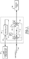
- High performance mass flow controller (MFC) 160 such as a ⁇ MFC manufactured and sold by the present assignee, includes a flow sensor 170 and an adjustable control valve 190.
- the sensor 170 senses the mass flow through the sensor, and provides a signal representative of the measured flow to the dedicated MFC controller 180.
- the dedicated controller 180 compares the measured flow with a flow set point so as to provide a control signal used to control the adjustable control valve 190 so that the output flow of the valve to the process tool 200, such as a process chamber, is maintained at the set point value.
- the MFC 160 has two modes of operation, providing one significant advantage over pressure based pulse gas delivery devices.
- a first mode is a traditional mass flow controller (MFC) mode, where a host controller 150 sends flow set point signals to the MFC 160 to control the flow delivered to the processing tool 200.
- a second mode is a pulse gas delivery (PGD) mode.
- PGD pulse gas delivery
- MFC 160 is arranged to receive the pulse profile and the necessary profile and sequencing of pulses so that the MFC can deliver a gas from the supply 140 to the chamber 200 in accordance with a recipe including a profile and sequence of timed pulses provided by the user.
- the profile and sequencing of the pulses can be initially programmed by the information being downloaded from the user interface/host controller 150 to the dedicated MFC controller 180.
- the downloaded profile and sequencing allows the MFC to carry out all of the sequencing steps in response to a single trigger signal from the interface/controller 150.
- the dedicated controller can be configured and arranged so as to carry out all of the sequencing steps in a well controlled and timely manner, freeing the host controller /interface to carry out all of its other functions without interfering with the pulse gas delivery.
- the PGD mode provides operational steps for three delivery types of pulse gas delivery processes- time based delivery, mole based delivery, and profile based delivery providing a further advantage over the pressure based gas pulse delivery devices.
- the user is required to configure and arrange the dedicated MFC controller 180 with the following parameters for the process that is to be controlled: (1) at least one targeted flow set point ( Q sp ), (2) at least one time length of the pulse-on period ( T on ), (3) at least one time length of the pulse-off period ( T off ), and (4) the total number of pulses (N) required to complete the process.
- the parameters are configured or downloaded from the host controller to the dedicated MFC controller of the MFC so that the MFC controller controls the pulse delivery as a function of these parameters.
- the host computer simply provides a trigger signal to the MFC, and the MFC carries out the sequence of pulses.
- the MFC 160 controls the PGD process according to the recipe by turning the MFC on (controlling the flow to the targeted flow set point by regulating the openness of the valve) and off (controlling the flow to zero by closing the valve) based on the prescribed pulse on period and the pulse off period for each pulse period. This results in very good control of the sequencing, timing and duration of the pulses.
- a user specifies the following parameters: (1) mole delivery set point ( n sp ), (2) the targeted time length of the pulse-on period ( T on ), (3) the targeted time length of the pulse-off period ( T off ), and (4) the number of pulses (N).
- the MFC 160 controls, and adjusts as necessary, the flow set point so as to control the number of moles delivered with each pulse. Based on these parameters, the MFC 160 automatically delivers N pulses of flow in a precise timing sequence, with each pulse delivering ⁇ n moles during the portion of each pulse on period ( T on ) that the MFC is on, and turning the MFC off for the pulse off period ( T off ).
- the MFC 160 will automatically adjust the flow set point ( Q sp ) based on the calculated mole amount of gas delivered of Eq. (1) using the flow sensor measurement ( Q ) in order to precisely deliver the desired number of moles within the targeted pulse-on period ( T on ) for each pulse.
- Mole based delivery is preferred (but not required) when multiple process tools are being used, or flow to different parts or devices of a process tool are required to be matched.
- multiple high performance MFCs are used to provide flow through the corresponding multiple delivery channels.
- each MFC 160 uses feedback control loop from its flow sensor 170 to control its valve 190.
- mole based pulse delivery can be used to ensure that the amount (moles) of gas delivered with each pulse in each delivery channel is the same, regardless of these factors, since mole delivery will be independent of these factors.
- feedback is used to correct the errors in the amount of gas delivered caused by valve response times.
- an off flow set point can be entered for delivery of gas during the T off period, instead of defaulting to zero.
- the third mode of operation is the profile pulse mode.
- a user creates a profile characterizing one or more pulses. For each pulse in the profile, the user specifies the flow set point and the corresponding on and off pulse period, i.e., (1) the flow set point Q sp1 and a corresponding first pulse on and off period ( T on1 T off1 ), (2) the flow set point Q sp2 and a corresponding second pulse on and off period ( T on2 T off2 ), ... (m) the flow set point Q spm and a corresponding m -th pulse on and off period ( T onm T offm ), etc..
- a set of parameters are provided for each pulse of the entire set of pulses, allowing the pulses to vary depending on the type of process being run.
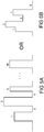
- Figs. 5A and 5B illustrate two examples of sets of pulse profiles. While in some embodiments, a user can define an ordinary on/off pulse with varying set points during T on (as seen in Fig. 5A ), in other embodiments, the user may enter more than one flow set point for both the on period and off period such that a stair-step type profile can be created as seen in Fig. 5B . The latter is possible because the MFC employs a proportional control valve.
- the proportional control valve can be set at any position between a totally open position and a totally closed position, providing a further advantage over the pressure based PGD device, such as the one shown in Fig. 1 .
- the user can also specify the mole delivery set point ( n spi ) instead of the flow set point Q spi along with the corresponding pulse on and off period ( T oni T offi ) for each of the pulses in the profile recipe.
- the MFC 160 coordinates the opening and closings operation of the control valve 190 and, accordingly, gas delivery.
- MFCs were analog devices incapable of accurately performing such PDG control responsibilities with such relatively short pulses.
- Newer, digital MFCs are capable of taking on the responsibility of controlling the proportional control valve of the MFC.
- higher repeatability and accuracy is achieved using the dedicated MFC controller 180 to run the PGD delivery process than would otherwise be possible.
- the host controller having to send signals to turn on and off the MFC, the process functions are carried out alone by the MFC 160 of Fig. 3 , eliminating a significant amount of hardware while assuring more accurate delivery.
- the required control recipe parameters vary based on the type of PGD mode being used, as described in more detail below.
- the host controller 150 may also send an abort signal to the MFC controller 180 at any time to abort pulse gas delivery. For example, if a safety check fails, the host controller 150 may demand the MFC 160 to immediately stop triggered gas delivery sequencing that is in process. Similarly, if the host controller 150 detects that incorrect gas delivery is being performed, then the host controller 150 may send an abort signal. In this way the host computer 150 can continue to monitor other processes, while the gas delivery steps are dedicated to the dedicated controller 180 of MFC 160.
- a host controller 150 can be used in conjunction with a plurality of MFCs 160 used with a corresponding number of delivery channels as mentioned above.
- the host controller 150 sends timely trigger signals to each MFC 160.
- the host controller 150 thus, can offset trigger signals to sequentially or simultaneously trigger the plurality of MFCs 160.
- the host controller 150 may stagger the trigger signals so that the delivery channels do not deliver gas simultaneously. For example, suppose control parameters define a T on of 0.25s and T off of 0.75s in each of two MFCs 160.
- the process tool 200 will receive delivery of gas equivalent to a T on of 0.25s and T off of 0.25s (if the two gas chambers are filled with the same gas).
- Test results using the disclosed approach indicated an improvement in the repeatability error over the experimental approach using a host computer to control the process by two orders of magnitude.
- a high performance MFC 220 can include one or more interfaces 230 which can be configured to provide communication ports capable of receiving both at least one digital signal input as shown at 240, and at least one analog signal input 250; and at least one digital signal output as shown at 310, and at least one analog signal output 300.
- a recipe can be downloaded to the MFC memory 260 through the digital input 240 of the interface, and the trigger signal can be provided through the analog input 240 of the interface to start the MFC delivery gas in accordance with the stored recipe.
- the processor/controller 270 receives signals from the flow sensor 280 of the MFC and controls the control valve 290 according to the recipe and the sensed flow.
- the one or more interfaces 230 can also be configured to include at least one analog signal output 300 and digital signal output 310. These outputs can be used for example as signals provided to other devices or tools.
- the illustrated embodiment of the mass flow controller (MFC) 220 is thus a programmable MFC, including at least an input (such as the analog signal input shown at 250) configured to receive an input signal, an output (such as analog signal output 300 or digital signal output 310) configured to provide an output signal, and a communication port (such as digital signal input 240) configured to receive program instructions including instructions for the programmed or operational configuration of the MFC 220, and programming data used by the MFC.
- an input such as the analog signal input shown at 250
- an output such as analog signal output 300 or digital signal output 310
- a communication port such as digital signal input 240
- MFC 220 also includes flow sensor 280 configured to sense the flow of gas through the mass flow controller, a control valve 290 configured to control the flow of gas though the mass flow controller and memory 260 configured and arranged to receive programming data including data determining the programmed configuration of the mass flow controller as either a digital or analog configuration for trigging the gas delivery.
- the processor/controller 270 operates the mass flow controller 220 in accordance with the programmed configuration.
- the programmed digital configuration enables the mass flow controller to respond to digital signals applied to the input 240.
- the programmed analog configuration enables the mass flow controller to respond to analog signals applied to the input 250.
- the input configured as a communication port in the illustrated embodiment is also configured to receive data relating to parameters associated with at least one of two modes of operation of the mass flow controller.
- the modes of operation of the mass flow controller can include a classic mass flow controller mode of operation, wherein the input signal represents the set point setting for operating the MFC in the classic mass flow controller mode of operation.
- the other mode of operation can include a pulse gas delivery mode of operation, wherein the input signal represents a pulse trigger signal for operating the MFC so as to deliver a sequence of pulses in the pulse gas delivery mode of operation.
- the communication port is configured to receive parameters for pulse gas delivery.
- the parameters can be associated with a mole delivery mode of gas pulse delivery operation.
- the parameters can also include the pulse-on period, pulse-off period, the mole delivery set point, and the number of pulses.
- the illustrated embodiment of the communication interface 230 thus includes the digital communication port, an analog input or pin for forming an input arranged to receive an analog trigger signal input, and an analog output or pin configured to form the output for providing an analog signal output.
- the analog signal output can be used to synchronize the operation of the MFC with the operation of another device or tool. This is particularly useful where two devices each provide a sequence of pulses (which can be the same or different sequence) which must be synchronized with each other, or the two devices each provide a pulse synchronized with the pulse of the other device.
- the other device can be, for example, another high performance MFC and/or a RF generator and/or a pressure controller. This enables the synchronization of the various tool devices when they are being used to simultaneously carry out parallel steps for a common process or different processes.
- a host computer at 350 can download the pulse sequences to each of the MFCs 360 over the digital communication bus 370.
- the outputs of the MFCs are connected in a successive daisy chain arrangement, and each output signal 380 can also be split and re-routed to provide to other devices on a process tool, such as a RF generator, a plasma generator or a pressure controller, and/or in other embodiments to tool devices on different process tools .
- a trigger signal is sent to the first MFC 360a.
- the first MFC 360a delivers a sequence of pulses in accordance with the sequence programmed in its memory.
- the synchronization output of the first MFC 360a is provided as a trigger signal input to the second MFC 360b as well as to the tool device of, for example, a RF generator,
- the sequence proceeds with each successive MFC 360.
- Each trigger signal thus synchronizes the operation of one MFC with the next MFC in the daisy chain arrangement of any number of MFCs (generally indicated in Fig. 7 by N).
- the synchronization signal of one MFC can be generated prior to the completion of the delivery of the sequence of pulses by the MFC.
- the synchronization signal can be generated simultaneously with the completion of the delivery of the sequence of pulses, or the synchronization signal can be generated after the completion of the delivery of the sequence of pulses by a predetermined delay.
- the pulse trigger signal can be a digital or an analog signal.
- the output signal is a TTL synchronization output signal for use by another device.
- the illustrated system embodiment shown can operate as a multi-channel gas delivery system including a plurality N of flow channels 380, each channel comprising a mass flow controller 360 configured to control the flow of gas through the corresponding channel.
- each MFC can be arranged to provide at least one pulse of gas, with the MFCs being connected in series (a daisy chain arrangement). In this way each MFC can provide the same or different gases to the tool, each as a pulse of a prescribed duration as best seen in Fig. 8 .
- the quantity (e.g., mass) of gas of each delivered pulse can vary from channel to the channel.
- the MFCs 360 can be synchronized to simultaneously deliver each pulse when the previous pulse ends.
- each successive pulse can be delayed relative to the previous pulse, or commence prior to the end of the previous pulse, or some combination of any two or all three synchronization arrangements.
- the digital communication port of each mass flow controller can be configured to receive data relating to parameters associated with at least one of two modes of operation of the mass flow controller.
- the MFC can be configured to operate in a classic mode of gas delivery operation, or pulse mode of gas delivery operation.
- a classic mode of gas delivery operation or pulse mode of gas delivery operation.
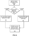
- the MFC when an input trigger is received at step 400, if the MFC is configured to operate in the classic mass flow controller mode at 402 it proceeds to step 404 and delivers a prescribed amount of gas by sensing the actual flow with the sensor, and controlling the control valve based on the sensed flow and the received flow setpoint.
- the MFC then proceeds to the step 406 and provides an output signal for the next MFC, or if functioning alone or if the last MFC in the chain, the process ends.
- the pulse mode the process proceeds from step 402 to 408 to deliver the prescribed amount of gas in pulses.
- the process then proceeds to step 406.
- the parameters can be associated with a mole delivery mode of gas pulse delivery operation.
- the parameters include the pulse-on period, pulse-off period, the mole delivery setpoint, and the number of pulses.
- the gas delivery system reliably measures the amount of material (mass) flowing into the semiconductor tool, and provides for accurate delivery of the mass of a gas in pulses of relatively short duration in a reliable and repeatable fashion. Further, the system employs a more simplified operation, while providing delivery of the desired number of moles of gas over a wide range of values, without the need to divert gas to achieve the accurate, reliable and repeatable results.
Landscapes
- Chemical & Material Sciences (AREA)
- Engineering & Computer Science (AREA)
- General Chemical & Material Sciences (AREA)
- Chemical Kinetics & Catalysis (AREA)
- Materials Engineering (AREA)
- Mechanical Engineering (AREA)
- Metallurgy (AREA)
- Organic Chemistry (AREA)
- Physics & Mathematics (AREA)
- General Physics & Mathematics (AREA)
- Automation & Control Theory (AREA)
- Flow Control (AREA)
- Drying Of Semiconductors (AREA)
- Chemical Vapour Deposition (AREA)
- Measuring Volume Flow (AREA)
- Transition And Organic Metals Composition Catalysts For Addition Polymerization (AREA)
Applications Claiming Priority (3)
| Application Number | Priority Date | Filing Date | Title |
|---|---|---|---|
| US14/209,216 US10126760B2 (en) | 2011-02-25 | 2014-03-13 | System for and method of fast pulse gas delivery |
| EP15760881.1A EP3117023B1 (de) | 2014-03-13 | 2015-02-11 | System und verfahren zur schnellen impulsgaszufuhr |
| PCT/US2015/015363 WO2015138073A1 (en) | 2014-03-13 | 2015-02-11 | System for and method of fast pulse gas delivery |
Related Parent Applications (1)
| Application Number | Title | Priority Date | Filing Date |
|---|---|---|---|
| EP15760881.1A Division EP3117023B1 (de) | 2014-03-13 | 2015-02-11 | System und verfahren zur schnellen impulsgaszufuhr |
Publications (2)
| Publication Number | Publication Date |
|---|---|
| EP3556903A1 true EP3556903A1 (de) | 2019-10-23 |
| EP3556903B1 EP3556903B1 (de) | 2021-09-22 |
Family
ID=54072260
Family Applications (2)
| Application Number | Title | Priority Date | Filing Date |
|---|---|---|---|
| EP15760881.1A Active EP3117023B1 (de) | 2014-03-13 | 2015-02-11 | System und verfahren zur schnellen impulsgaszufuhr |
| EP19161633.3A Active EP3556903B1 (de) | 2014-03-13 | 2015-02-11 | System und verfahren zur schnellen impulsgaszufuhr |
Family Applications Before (1)
| Application Number | Title | Priority Date | Filing Date |
|---|---|---|---|
| EP15760881.1A Active EP3117023B1 (de) | 2014-03-13 | 2015-02-11 | System und verfahren zur schnellen impulsgaszufuhr |
Country Status (7)
| Country | Link |
|---|---|
| EP (2) | EP3117023B1 (de) |
| JP (2) | JP6672160B2 (de) |
| KR (2) | KR102446557B1 (de) |
| CN (1) | CN106103796B (de) |
| SG (1) | SG11201607251XA (de) |
| TW (2) | TWI615698B (de) |
| WO (1) | WO2015138073A1 (de) |
Families Citing this family (8)
| Publication number | Priority date | Publication date | Assignee | Title |
|---|---|---|---|---|
| JP6978865B2 (ja) | 2017-07-05 | 2021-12-08 | 株式会社堀場エステック | 流体制御装置、流体制御方法、及び、流体制御装置用プログラム |
| JP7107648B2 (ja) * | 2017-07-11 | 2022-07-27 | 株式会社堀場エステック | 流体制御装置、流体制御システム、流体制御方法、及び、流体制御装置用プログラム |
| US11429409B2 (en) * | 2018-09-04 | 2022-08-30 | Lam Research Corporation | Software emulator for hardware components in a gas delivery system of substrate processing system |
| JP6896682B2 (ja) * | 2018-09-04 | 2021-06-30 | 株式会社Kokusai Electric | 基板処理装置および半導体装置の製造方法 |
| US10725484B2 (en) | 2018-09-07 | 2020-07-28 | Mks Instruments, Inc. | Method and apparatus for pulse gas delivery using an external pressure trigger |
| JP7243960B2 (ja) * | 2019-01-11 | 2023-03-22 | Smc株式会社 | 電磁弁システム |
| US11404290B2 (en) * | 2019-04-05 | 2022-08-02 | Mks Instruments, Inc. | Method and apparatus for pulse gas delivery |
| US11487304B2 (en) * | 2021-01-08 | 2022-11-01 | Applied Materials, Inc. | Process fluid path switching in recipe operations |
Citations (3)
| Publication number | Priority date | Publication date | Assignee | Title |
|---|---|---|---|---|
| US20060130744A1 (en) * | 2004-12-17 | 2006-06-22 | Clark William R | Pulsed mass flow delivery system and method |
| US20080167748A1 (en) * | 2007-01-10 | 2008-07-10 | Mks Instruments, Inc. | Integrated pressure and flow ratio control system |
| US20130186332A1 (en) * | 2012-01-25 | 2013-07-25 | Tokyo Electron Limited | Processing apparatus and process status checking method |
Family Cites Families (18)
| Publication number | Priority date | Publication date | Assignee | Title |
|---|---|---|---|---|
| JP2848188B2 (ja) * | 1993-05-18 | 1999-01-20 | 株式会社日立製作所 | 単独及び協調制御機能を有する制御システム |
| JP2000012464A (ja) * | 1998-06-23 | 2000-01-14 | Kokusai Electric Co Ltd | 処理装置のコントローラ |
| US6389364B1 (en) * | 1999-07-10 | 2002-05-14 | Mykrolis Corporation | System and method for a digital mass flow controller |
| US6405745B1 (en) * | 2000-03-22 | 2002-06-18 | Delphi Technologies, Inc. | Ultra accurate gas injection system |
| US6418954B1 (en) * | 2001-04-17 | 2002-07-16 | Mks Instruments, Inc. | System and method for dividing flow |
| US6766260B2 (en) * | 2002-01-04 | 2004-07-20 | Mks Instruments, Inc. | Mass flow ratio system and method |
| US6973508B2 (en) * | 2002-02-12 | 2005-12-06 | Fisher-Rosemount Systems, Inc. | Highly versatile process control system controller |
| WO2004010234A2 (en) * | 2002-07-19 | 2004-01-29 | Celerity Group, Inc. | Methods and apparatus for pressure compensation in a mass flow controller |
| US7369959B2 (en) * | 2002-11-26 | 2008-05-06 | Intercat Equipment, Inc. | Fluid catalytic cracking catalyst injection system and method for communicating with same |
| US7628860B2 (en) * | 2004-04-12 | 2009-12-08 | Mks Instruments, Inc. | Pulsed mass flow delivery system and method |
| US10054444B2 (en) * | 2009-05-29 | 2018-08-21 | Qualcomm Incorporated | Method and apparatus for accurate acquisition of inertial sensor data |
| CN102804354B (zh) * | 2010-03-05 | 2015-07-08 | 应用材料公司 | 气体分布器的多个气体喷嘴的流动性质的测量 |
| CN103597325B (zh) * | 2010-08-24 | 2016-09-28 | 因万西斯系统股份有限公司 | 多相计量 |
| WO2012100181A1 (en) * | 2011-01-20 | 2012-07-26 | Hitachi Metals, Ltd. | Mass flow controller with onboard diagnostics, prognostics, and data logging |
| US10353408B2 (en) * | 2011-02-25 | 2019-07-16 | Mks Instruments, Inc. | System for and method of fast pulse gas delivery |
| US8849466B2 (en) * | 2011-10-04 | 2014-09-30 | Mks Instruments, Inc. | Method of and apparatus for multiple channel flow ratio controller system |
| CN202677205U (zh) * | 2012-04-23 | 2013-01-16 | 江苏迈拓智能仪表有限公司 | 一种超声计量和流量控制系统 |
| JP6094994B2 (ja) | 2013-02-04 | 2017-03-15 | 大陽日酸株式会社 | 原料ガス生成供給方法 |
-
2015
- 2015-02-11 CN CN201580013678.6A patent/CN106103796B/zh not_active Expired - Fee Related
- 2015-02-11 SG SG11201607251XA patent/SG11201607251XA/en unknown
- 2015-02-11 KR KR1020217041684A patent/KR102446557B1/ko active Active
- 2015-02-11 KR KR1020167024706A patent/KR102363639B1/ko active Active
- 2015-02-11 JP JP2016556952A patent/JP6672160B2/ja active Active
- 2015-02-11 EP EP15760881.1A patent/EP3117023B1/de active Active
- 2015-02-11 EP EP19161633.3A patent/EP3556903B1/de active Active
- 2015-02-11 WO PCT/US2015/015363 patent/WO2015138073A1/en not_active Ceased
- 2015-02-26 TW TW105139795A patent/TWI615698B/zh active
- 2015-02-26 TW TW104106153A patent/TWI569121B/zh active
-
2020
- 2020-03-04 JP JP2020037091A patent/JP6923693B2/ja active Active
Patent Citations (3)
| Publication number | Priority date | Publication date | Assignee | Title |
|---|---|---|---|---|
| US20060130744A1 (en) * | 2004-12-17 | 2006-06-22 | Clark William R | Pulsed mass flow delivery system and method |
| US20080167748A1 (en) * | 2007-01-10 | 2008-07-10 | Mks Instruments, Inc. | Integrated pressure and flow ratio control system |
| US20130186332A1 (en) * | 2012-01-25 | 2013-07-25 | Tokyo Electron Limited | Processing apparatus and process status checking method |
Also Published As
| Publication number | Publication date |
|---|---|
| SG11201607251XA (en) | 2016-09-29 |
| JP2020109853A (ja) | 2020-07-16 |
| JP6923693B2 (ja) | 2021-08-25 |
| EP3556903B1 (de) | 2021-09-22 |
| JP2017509793A (ja) | 2017-04-06 |
| JP6672160B2 (ja) | 2020-03-25 |
| CN106103796B (zh) | 2019-10-22 |
| TWI615698B (zh) | 2018-02-21 |
| TWI569121B (zh) | 2017-02-01 |
| KR20210158405A (ko) | 2021-12-30 |
| WO2015138073A1 (en) | 2015-09-17 |
| KR20160132835A (ko) | 2016-11-21 |
| EP3117023A1 (de) | 2017-01-18 |
| EP3117023A4 (de) | 2017-11-29 |
| KR102446557B1 (ko) | 2022-09-23 |
| CN106103796A (zh) | 2016-11-09 |
| TW201719313A (zh) | 2017-06-01 |
| KR102363639B1 (ko) | 2022-02-16 |
| EP3117023B1 (de) | 2019-04-10 |
| TW201604670A (zh) | 2016-02-01 |
Similar Documents
| Publication | Publication Date | Title |
|---|---|---|
| US10969799B2 (en) | System for and method of fast pulse gas delivery | |
| US10353408B2 (en) | System for and method of fast pulse gas delivery | |
| EP3117023B1 (de) | System und verfahren zur schnellen impulsgaszufuhr | |
| US10031531B2 (en) | System for and method of multiple channel fast pulse gas delivery | |
| US20130025786A1 (en) | Systems for and methods of controlling time-multiplexed deep reactive-ion etching processes | |
| CN103221575B (zh) | 多通道脉冲气体输送系统的方法和装置 |
Legal Events
| Date | Code | Title | Description |
|---|---|---|---|
| PUAI | Public reference made under article 153(3) epc to a published international application that has entered the european phase |
Free format text: ORIGINAL CODE: 0009012 |
|
| STAA | Information on the status of an ep patent application or granted ep patent |
Free format text: STATUS: REQUEST FOR EXAMINATION WAS MADE |
|
| 17P | Request for examination filed |
Effective date: 20190308 |
|
| AC | Divisional application: reference to earlier application |
Ref document number: 3117023 Country of ref document: EP Kind code of ref document: P |
|
| AK | Designated contracting states |
Kind code of ref document: A1 Designated state(s): AL AT BE BG CH CY CZ DE DK EE ES FI FR GB GR HR HU IE IS IT LI LT LU LV MC MK MT NL NO PL PT RO RS SE SI SK SM TR |
|
| RIC1 | Information provided on ipc code assigned before grant |
Ipc: C23C 16/52 20060101ALI20200923BHEP Ipc: C23C 16/455 20060101AFI20200923BHEP Ipc: C23C 16/448 20060101ALI20200923BHEP Ipc: G05D 7/06 20060101ALI20200923BHEP |
|
| GRAP | Despatch of communication of intention to grant a patent |
Free format text: ORIGINAL CODE: EPIDOSNIGR1 |
|
| STAA | Information on the status of an ep patent application or granted ep patent |
Free format text: STATUS: GRANT OF PATENT IS INTENDED |
|
| INTG | Intention to grant announced |
Effective date: 20201201 |
|
| GRAJ | Information related to disapproval of communication of intention to grant by the applicant or resumption of examination proceedings by the epo deleted |
Free format text: ORIGINAL CODE: EPIDOSDIGR1 |
|
| STAA | Information on the status of an ep patent application or granted ep patent |
Free format text: STATUS: REQUEST FOR EXAMINATION WAS MADE |
|
| INTC | Intention to grant announced (deleted) | ||
| GRAP | Despatch of communication of intention to grant a patent |
Free format text: ORIGINAL CODE: EPIDOSNIGR1 |
|
| STAA | Information on the status of an ep patent application or granted ep patent |
Free format text: STATUS: GRANT OF PATENT IS INTENDED |
|
| INTG | Intention to grant announced |
Effective date: 20210429 |
|
| GRAS | Grant fee paid |
Free format text: ORIGINAL CODE: EPIDOSNIGR3 |
|
| GRAA | (expected) grant |
Free format text: ORIGINAL CODE: 0009210 |
|
| STAA | Information on the status of an ep patent application or granted ep patent |
Free format text: STATUS: THE PATENT HAS BEEN GRANTED |
|
| AC | Divisional application: reference to earlier application |
Ref document number: 3117023 Country of ref document: EP Kind code of ref document: P |
|
| AK | Designated contracting states |
Kind code of ref document: B1 Designated state(s): AL AT BE BG CH CY CZ DE DK EE ES FI FR GB GR HR HU IE IS IT LI LT LU LV MC MK MT NL NO PL PT RO RS SE SI SK SM TR |
|
| REG | Reference to a national code |
Ref country code: GB Ref legal event code: FG4D |
|
| REG | Reference to a national code |
Ref country code: IE Ref legal event code: FG4D |
|
| REG | Reference to a national code |
Ref country code: DE Ref legal event code: R096 Ref document number: 602015073626 Country of ref document: DE |
|
| REG | Reference to a national code |
Ref country code: CH Ref legal event code: EP Ref country code: AT Ref legal event code: REF Ref document number: 1432394 Country of ref document: AT Kind code of ref document: T Effective date: 20211015 |
|
| REG | Reference to a national code |
Ref country code: LT Ref legal event code: MG9D |
|
| REG | Reference to a national code |
Ref country code: NL Ref legal event code: MP Effective date: 20210922 |
|
| PG25 | Lapsed in a contracting state [announced via postgrant information from national office to epo] |
Ref country code: LT Free format text: LAPSE BECAUSE OF FAILURE TO SUBMIT A TRANSLATION OF THE DESCRIPTION OR TO PAY THE FEE WITHIN THE PRESCRIBED TIME-LIMIT Effective date: 20210922 Ref country code: BG Free format text: LAPSE BECAUSE OF FAILURE TO SUBMIT A TRANSLATION OF THE DESCRIPTION OR TO PAY THE FEE WITHIN THE PRESCRIBED TIME-LIMIT Effective date: 20211222 Ref country code: HR Free format text: LAPSE BECAUSE OF FAILURE TO SUBMIT A TRANSLATION OF THE DESCRIPTION OR TO PAY THE FEE WITHIN THE PRESCRIBED TIME-LIMIT Effective date: 20210922 Ref country code: NO Free format text: LAPSE BECAUSE OF FAILURE TO SUBMIT A TRANSLATION OF THE DESCRIPTION OR TO PAY THE FEE WITHIN THE PRESCRIBED TIME-LIMIT Effective date: 20211222 Ref country code: FI Free format text: LAPSE BECAUSE OF FAILURE TO SUBMIT A TRANSLATION OF THE DESCRIPTION OR TO PAY THE FEE WITHIN THE PRESCRIBED TIME-LIMIT Effective date: 20210922 Ref country code: SE Free format text: LAPSE BECAUSE OF FAILURE TO SUBMIT A TRANSLATION OF THE DESCRIPTION OR TO PAY THE FEE WITHIN THE PRESCRIBED TIME-LIMIT Effective date: 20210922 Ref country code: RS Free format text: LAPSE BECAUSE OF FAILURE TO SUBMIT A TRANSLATION OF THE DESCRIPTION OR TO PAY THE FEE WITHIN THE PRESCRIBED TIME-LIMIT Effective date: 20210922 |
|
| REG | Reference to a national code |
Ref country code: AT Ref legal event code: MK05 Ref document number: 1432394 Country of ref document: AT Kind code of ref document: T Effective date: 20210922 |
|
| PG25 | Lapsed in a contracting state [announced via postgrant information from national office to epo] |
Ref country code: LV Free format text: LAPSE BECAUSE OF FAILURE TO SUBMIT A TRANSLATION OF THE DESCRIPTION OR TO PAY THE FEE WITHIN THE PRESCRIBED TIME-LIMIT Effective date: 20210922 Ref country code: GR Free format text: LAPSE BECAUSE OF FAILURE TO SUBMIT A TRANSLATION OF THE DESCRIPTION OR TO PAY THE FEE WITHIN THE PRESCRIBED TIME-LIMIT Effective date: 20211223 |
|
| PG25 | Lapsed in a contracting state [announced via postgrant information from national office to epo] |
Ref country code: AT Free format text: LAPSE BECAUSE OF FAILURE TO SUBMIT A TRANSLATION OF THE DESCRIPTION OR TO PAY THE FEE WITHIN THE PRESCRIBED TIME-LIMIT Effective date: 20210922 |
|
| PG25 | Lapsed in a contracting state [announced via postgrant information from national office to epo] |
Ref country code: IS Free format text: LAPSE BECAUSE OF FAILURE TO SUBMIT A TRANSLATION OF THE DESCRIPTION OR TO PAY THE FEE WITHIN THE PRESCRIBED TIME-LIMIT Effective date: 20220122 Ref country code: SK Free format text: LAPSE BECAUSE OF FAILURE TO SUBMIT A TRANSLATION OF THE DESCRIPTION OR TO PAY THE FEE WITHIN THE PRESCRIBED TIME-LIMIT Effective date: 20210922 Ref country code: RO Free format text: LAPSE BECAUSE OF FAILURE TO SUBMIT A TRANSLATION OF THE DESCRIPTION OR TO PAY THE FEE WITHIN THE PRESCRIBED TIME-LIMIT Effective date: 20210922 Ref country code: PT Free format text: LAPSE BECAUSE OF FAILURE TO SUBMIT A TRANSLATION OF THE DESCRIPTION OR TO PAY THE FEE WITHIN THE PRESCRIBED TIME-LIMIT Effective date: 20220124 Ref country code: PL Free format text: LAPSE BECAUSE OF FAILURE TO SUBMIT A TRANSLATION OF THE DESCRIPTION OR TO PAY THE FEE WITHIN THE PRESCRIBED TIME-LIMIT Effective date: 20210922 Ref country code: NL Free format text: LAPSE BECAUSE OF FAILURE TO SUBMIT A TRANSLATION OF THE DESCRIPTION OR TO PAY THE FEE WITHIN THE PRESCRIBED TIME-LIMIT Effective date: 20210922 Ref country code: ES Free format text: LAPSE BECAUSE OF FAILURE TO SUBMIT A TRANSLATION OF THE DESCRIPTION OR TO PAY THE FEE WITHIN THE PRESCRIBED TIME-LIMIT Effective date: 20210922 Ref country code: EE Free format text: LAPSE BECAUSE OF FAILURE TO SUBMIT A TRANSLATION OF THE DESCRIPTION OR TO PAY THE FEE WITHIN THE PRESCRIBED TIME-LIMIT Effective date: 20210922 Ref country code: CZ Free format text: LAPSE BECAUSE OF FAILURE TO SUBMIT A TRANSLATION OF THE DESCRIPTION OR TO PAY THE FEE WITHIN THE PRESCRIBED TIME-LIMIT Effective date: 20210922 Ref country code: AL Free format text: LAPSE BECAUSE OF FAILURE TO SUBMIT A TRANSLATION OF THE DESCRIPTION OR TO PAY THE FEE WITHIN THE PRESCRIBED TIME-LIMIT Effective date: 20210922 |
|
| REG | Reference to a national code |
Ref country code: DE Ref legal event code: R097 Ref document number: 602015073626 Country of ref document: DE |
|
| PG25 | Lapsed in a contracting state [announced via postgrant information from national office to epo] |
Ref country code: DK Free format text: LAPSE BECAUSE OF FAILURE TO SUBMIT A TRANSLATION OF THE DESCRIPTION OR TO PAY THE FEE WITHIN THE PRESCRIBED TIME-LIMIT Effective date: 20210922 |
|
| PLBE | No opposition filed within time limit |
Free format text: ORIGINAL CODE: 0009261 |
|
| STAA | Information on the status of an ep patent application or granted ep patent |
Free format text: STATUS: NO OPPOSITION FILED WITHIN TIME LIMIT |
|
| 26N | No opposition filed |
Effective date: 20220623 |
|
| PG25 | Lapsed in a contracting state [announced via postgrant information from national office to epo] |
Ref country code: MC Free format text: LAPSE BECAUSE OF FAILURE TO SUBMIT A TRANSLATION OF THE DESCRIPTION OR TO PAY THE FEE WITHIN THE PRESCRIBED TIME-LIMIT Effective date: 20210922 |
|
| REG | Reference to a national code |
Ref country code: CH Ref legal event code: PL |
|
| REG | Reference to a national code |
Ref country code: BE Ref legal event code: MM Effective date: 20220228 |
|
| PG25 | Lapsed in a contracting state [announced via postgrant information from national office to epo] |
Ref country code: LU Free format text: LAPSE BECAUSE OF NON-PAYMENT OF DUE FEES Effective date: 20220211 |
|
| PG25 | Lapsed in a contracting state [announced via postgrant information from national office to epo] |
Ref country code: SI Free format text: LAPSE BECAUSE OF FAILURE TO SUBMIT A TRANSLATION OF THE DESCRIPTION OR TO PAY THE FEE WITHIN THE PRESCRIBED TIME-LIMIT Effective date: 20210922 |
|
| PG25 | Lapsed in a contracting state [announced via postgrant information from national office to epo] |
Ref country code: FR Free format text: LAPSE BECAUSE OF NON-PAYMENT OF DUE FEES Effective date: 20220228 |
|
| PG25 | Lapsed in a contracting state [announced via postgrant information from national office to epo] |
Ref country code: LI Free format text: LAPSE BECAUSE OF NON-PAYMENT OF DUE FEES Effective date: 20220228 Ref country code: IT Free format text: LAPSE BECAUSE OF FAILURE TO SUBMIT A TRANSLATION OF THE DESCRIPTION OR TO PAY THE FEE WITHIN THE PRESCRIBED TIME-LIMIT Effective date: 20210922 Ref country code: IE Free format text: LAPSE BECAUSE OF NON-PAYMENT OF DUE FEES Effective date: 20220211 Ref country code: CH Free format text: LAPSE BECAUSE OF NON-PAYMENT OF DUE FEES Effective date: 20220228 |
|
| PG25 | Lapsed in a contracting state [announced via postgrant information from national office to epo] |
Ref country code: BE Free format text: LAPSE BECAUSE OF NON-PAYMENT OF DUE FEES Effective date: 20220228 |
|
| PG25 | Lapsed in a contracting state [announced via postgrant information from national office to epo] |
Ref country code: SM Free format text: LAPSE BECAUSE OF FAILURE TO SUBMIT A TRANSLATION OF THE DESCRIPTION OR TO PAY THE FEE WITHIN THE PRESCRIBED TIME-LIMIT Effective date: 20210922 Ref country code: MK Free format text: LAPSE BECAUSE OF FAILURE TO SUBMIT A TRANSLATION OF THE DESCRIPTION OR TO PAY THE FEE WITHIN THE PRESCRIBED TIME-LIMIT Effective date: 20210922 Ref country code: CY Free format text: LAPSE BECAUSE OF FAILURE TO SUBMIT A TRANSLATION OF THE DESCRIPTION OR TO PAY THE FEE WITHIN THE PRESCRIBED TIME-LIMIT Effective date: 20210922 |
|
| PG25 | Lapsed in a contracting state [announced via postgrant information from national office to epo] |
Ref country code: HU Free format text: LAPSE BECAUSE OF FAILURE TO SUBMIT A TRANSLATION OF THE DESCRIPTION OR TO PAY THE FEE WITHIN THE PRESCRIBED TIME-LIMIT; INVALID AB INITIO Effective date: 20150211 |
|
| PG25 | Lapsed in a contracting state [announced via postgrant information from national office to epo] |
Ref country code: MT Free format text: LAPSE BECAUSE OF FAILURE TO SUBMIT A TRANSLATION OF THE DESCRIPTION OR TO PAY THE FEE WITHIN THE PRESCRIBED TIME-LIMIT Effective date: 20210922 |
|
| PG25 | Lapsed in a contracting state [announced via postgrant information from national office to epo] |
Ref country code: TR Free format text: LAPSE BECAUSE OF FAILURE TO SUBMIT A TRANSLATION OF THE DESCRIPTION OR TO PAY THE FEE WITHIN THE PRESCRIBED TIME-LIMIT Effective date: 20210922 |
|
| PGFP | Annual fee paid to national office [announced via postgrant information from national office to epo] |
Ref country code: GB Payment date: 20260223 Year of fee payment: 12 |
|
| PGFP | Annual fee paid to national office [announced via postgrant information from national office to epo] |
Ref country code: DE Payment date: 20260220 Year of fee payment: 12 |