EP3556718B1 - Concrete pump vehicle - Google Patents
Concrete pump vehicle Download PDFInfo
- Publication number
- EP3556718B1 EP3556718B1 EP19169023.9A EP19169023A EP3556718B1 EP 3556718 B1 EP3556718 B1 EP 3556718B1 EP 19169023 A EP19169023 A EP 19169023A EP 3556718 B1 EP3556718 B1 EP 3556718B1
- Authority
- EP
- European Patent Office
- Prior art keywords
- leg
- truck
- concrete pump
- mounted concrete
- legs
- Prior art date
- Legal status (The legal status is an assumption and is not a legal conclusion. Google has not performed a legal analysis and makes no representation as to the accuracy of the status listed.)
- Active
Links
- 210000003414 extremity Anatomy 0.000 claims 8
- 210000003141 lower extremity Anatomy 0.000 claims 1
- 210000001364 upper extremity Anatomy 0.000 claims 1
- 230000002787 reinforcement Effects 0.000 description 12
- 239000003351 stiffener Substances 0.000 description 10
- 239000000463 material Substances 0.000 description 4
- 238000005452 bending Methods 0.000 description 2
- 238000004519 manufacturing process Methods 0.000 description 2
- 229910052751 metal Inorganic materials 0.000 description 2
- OKTJSMMVPCPJKN-UHFFFAOYSA-N Carbon Chemical compound [C] OKTJSMMVPCPJKN-UHFFFAOYSA-N 0.000 description 1
- 229910000831 Steel Inorganic materials 0.000 description 1
- 230000001154 acute effect Effects 0.000 description 1
- 108010081181 calcium-binding protein (brain) Proteins 0.000 description 1
- 229910052799 carbon Inorganic materials 0.000 description 1
- 239000002131 composite material Substances 0.000 description 1
- 238000010276 construction Methods 0.000 description 1
- 230000008878 coupling Effects 0.000 description 1
- 238000010168 coupling process Methods 0.000 description 1
- 238000005859 coupling reaction Methods 0.000 description 1
- 230000001419 dependent effect Effects 0.000 description 1
- 239000000835 fiber Substances 0.000 description 1
- 239000002184 metal Substances 0.000 description 1
- 239000007769 metal material Substances 0.000 description 1
- 150000002739 metals Chemical class 0.000 description 1
- 238000005086 pumping Methods 0.000 description 1
- 230000003014 reinforcing effect Effects 0.000 description 1
- 239000010959 steel Substances 0.000 description 1
- 230000007704 transition Effects 0.000 description 1
Images
Classifications
-
- B—PERFORMING OPERATIONS; TRANSPORTING
- B66—HOISTING; LIFTING; HAULING
- B66C—CRANES; LOAD-ENGAGING ELEMENTS OR DEVICES FOR CRANES, CAPSTANS, WINCHES, OR TACKLES
- B66C23/00—Cranes comprising essentially a beam, boom, or triangular structure acting as a cantilever and mounted for translatory of swinging movements in vertical or horizontal planes or a combination of such movements, e.g. jib-cranes, derricks, tower cranes
- B66C23/62—Constructional features or details
- B66C23/72—Counterweights or supports for balancing lifting couples
- B66C23/78—Supports, e.g. outriggers, for mobile cranes
-
- E—FIXED CONSTRUCTIONS
- E04—BUILDING
- E04G—SCAFFOLDING; FORMS; SHUTTERING; BUILDING IMPLEMENTS OR AIDS, OR THEIR USE; HANDLING BUILDING MATERIALS ON THE SITE; REPAIRING, BREAKING-UP OR OTHER WORK ON EXISTING BUILDINGS
- E04G21/00—Preparing, conveying, or working-up building materials or building elements in situ; Other devices or measures for constructional work
- E04G21/02—Conveying or working-up concrete or similar masses able to be heaped or cast
- E04G21/04—Devices for both conveying and distributing
- E04G21/0418—Devices for both conveying and distributing with distribution hose
- E04G21/0436—Devices for both conveying and distributing with distribution hose on a mobile support, e.g. truck
Definitions
- the invention relates to a truck-mounted concrete pump with at least one rear pivoting leg and at least one front pivoting leg, the front pivoting leg comprising a leg box and at least one inner part that can be telescoped thereto, and the rear pivoting leg comprising an outer part with an upper and a lower leg, between which the inner part of the front swivel leg can be stored in a telescoping and swiveled-in state.
- State-of-the-art truck-mounted concrete pumps typically include pivoting legs for supporting the truck-mounted concrete pump in a working condition.
- a placing boom of the truck-mounted concrete pump can be extended and concrete can be placed in a construction site area, for example, by means of the concrete pump and the placing boom.
- the swivel legs of the truck-mounted concrete pump can be arranged or combined in different ways.
- a retracted and pivoted front telescopic leg or swivel leg of a truck-mounted concrete pump is required in one Driving condition of the machine usually space in the rear pivoting leg or space in the area of a recess in the rear pivoting leg.
- the space requirement depends on the length of the pivoting legs and the design of the truck-mounted concrete pump's mast bracket.
- the rear swivel legs of all truck-mounted concrete pumps that are similar to those in the EP 1 090 195 B1 correspond to the type shown, in the joint areas very long, openings.
- the two legs of the opening act as a bending beam when the corresponding pivot leg is loaded.
- This opening proves to be unfavorable for dissipating the loads of the placing boom acting on the rear swivel legs during pumping operation into the subsoil, since the load-bearing cross-sections in the area of the opening can only have very small cross-sections for geometric reasons, which is caused by comparatively large wall thicknesses in the corresponding areas must be balanced.
- the object of the invention is to provide an improved truck-mounted concrete pump in which, in particular, lower production costs and a lower component weight are achieved by correspondingly improving the structure of the pivoting legs.
- a truck-mounted concrete pump is provided with at least one rear pivoting leg and at least one front pivoting leg, the front Pivoting leg comprises a leg box and at least one inner part telescopic thereto. It is also conceivable that the pivoting legs are designed to be telescopic several times.
- the rear pivoting leg comprises an outer part with an upper and a lower leg between which the inner part of the front pivoting leg can be stored in a telescoped and pivoted state. According to the invention, it is provided that the two legs are coupled to one another by means of at least one diagonal reinforcement on the outside of the rear pivoting leg. According to the invention, exactly one diagonal bracing can of course also be provided.
- the idea on which the invention is based is therefore to connect the lower leg of the rear pivoting leg on its outside diagonally from a lower hinge point of the rear pivoting leg to the leg-side end of the upper leg and/or in the opposite direction. In this way a very stable, truss-like triangle is created. As a result, the rear swivel leg can be stiffened with relatively little outlay on material and thus in a way that saves weight and costs.
- the outside of the rear swing leg is the side not penetrated by the telescopic leg when angling the front and rear legs toward each other to support the machine.
- the two legs in the height direction at least in sections or over their entirety Length are coupled solely by the diagonal bracing.
- the diagonal bracing is the sole connection of the legs and no other connecting means or connections are provided.
- a pivot axis can be provided at the ends of the legs, about which the pivoting leg is or both pivoting legs can be pivoted and which inevitably represents a further, albeit different, type of connection between the two legs.
- the diagonal bracing extends to an innermost section of one of the legs.
- This innermost portion may include the portion of the leg in which the pivot axis of the leg is located and which is the portion of the pivot leg closest to the truck-mounted concrete pump.
- the diagonal bracing extends up to a pivot axis of the rear pivot leg.
- the pivot axis can be arranged in the area of the innermost section of the pivot leg and set up to pivot the pivot leg relative to the truck-mounted concrete pump.
- a U-shaped, triangular or polygonal opening is formed between the legs, which is open in particular to the outside.
- an arcuate or angular area can form the outer part of the opening.
- the opening itself can be aligned horizontally, so that the inner part of the front pivoting leg can be pushed at least partially into the opening of the rear pivoting leg.
- the radius of the opening may be between one-fourth and one-half the height of the rear pivot leg.
- the inner part of the front pivoting leg is framed by the legs and the diagonal bracing of the rear pivoting leg in its telescoped state.
- the legs and the diagonal bracing thus at least partially enclose the inner part of the pivoting leg in the telescoped-in state.
- the inner part of the swivel leg or the inner telescoping part can be visible from the outside in the telescoped state through recesses in the area of the outer part.
- the diagonal bracing is at least as long as the distance between the two legs and/or at most twice as long as one of the legs. In the shortest version, the diagonal bracing is just as long as the distance between the two legs. The diagonal bracing can thus be arranged perpendicularly to the legs. The concept of diagonal bracing is therefore not to be understood as limiting. It is alternatively or additionally conceivable that the diagonal bracing extends at least half and at most twice as far in the height direction as one of the legs.
- the diagonal reinforcement has at least partially a constant profile in its longitudinal direction and/or has a greater length than width.
- the diagonal stiffener can thus be designed as a part that is elongated overall.
- diagonal stiffeners are provided on the rear swivel leg.
- the diagonal braces may be located on opposite sides of the pivot leg or on the same side of the pivot leg.
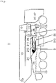
- figure 1 shows a truck-mounted concrete pump 1 according to the invention with a placing boom 10, via which concrete can be transported or pumped from a concrete mixer to a placement site.
- the placing boom 10 is coupled to the rest of the structure of the truck-mounted concrete pump 1 via a boom bracket 11 .
- the truck-mounted concrete pump according to figure 1 comprises two front pivoting legs 3 and two rear pivoting legs 2, the front pivoting legs 3 being able to comprise an in particular closed leg box 26.
- a front swivel leg 3 and a rear swivel leg 2 of the right side of the truck-mounted concrete pump 1 are shown.
- the truck-mounted concrete pump 1 can be designed as a truck 27 or as a working device with a driver's cab 27'.
- the truck-mounted concrete pump 1 comprises at least one rear pivoting leg 2 with an outer part 21.
- the front pivoting leg 3 has a leg box 26 in which an inner part 22 is slidably or telescopically mounted.
- the outer part 21 of the rear pivoting leg 2 comprises an upper leg 211 and a lower leg 212. Between the two legs 211, 212, the inner part 22 of the front pivoting leg 3 is in a figure 1 Can be stored in the telescoped and pivoted-in state shown.
- the inner part 22 of the front swivel leg 3 can also be referred to as a telescopic leg 22 .
- the two legs 211, 212 are coupled to one another by means of at least one diagonal stiffener 213.
- the two legs 211, 212 define an opening 24 together with a rounded or angular section.
- the two legs 211, 212 run in the longitudinal direction of the pivoting leg between the curved or angular area of the opening 24 and the pivot axis 23.
- the pivot axis 23 is set up for this purpose to pivot the pivoting legs 2, 3 relative to the truck-mounted concrete pump 1. It is conceivable that both pivoting legs 2, 3 can be pivoted relative to the rest of the structure of the truck-mounted concrete pump 1 via a common bolt or a corresponding common pivot axis 23.
- the two legs 211, 212 are in the height direction or in the vertical direction in the figure 1 shown embodiment coupled over its entire length solely by the diagonal brace 213. Only the pivot axis 23, which is arranged in the innermost area of the pivot leg 2, can be regarded as an additional coupling.
- the pivot axis 23 can be made movable relative to the components of the pivot leg 2 mentioned, while the legs 211, 212 and the diagonal reinforcement 213 can be made in one piece and/or cannot be adjusted relative to one another or can be rigid. It is conceivable to provide or cover the side area or intermediate space defined by the legs 211, 212 together with the diagonal reinforcement 213 with a cover plate.
- the legs 211, 212 and/or the diagonal stiffener 213 can be designed in one piece with one another, for example as burnt-out metal elements or as a single sheet. In addition or as an alternative, materials other than metals can also be used. It is conceivable that the diagonal reinforcement 213 is produced, for example, as a strut made of a metallic or non-metallic material such as a fiber composite material (eg based on carbon). This strut can be screwed and/or bolted to the legs 211, 212 and be set up in particular to absorb tensile loads.
- the diagonal stiffener 213 runs from the outside above, that is to say in the figure at the top left, to the inside below, that is to say in the figure at the bottom right. This results in a Z- or S-shaped stiffening.
- An alternative or additional reverse arrangement of the diagonal bracing is also conceivable.
- the diagonal bracing 213 can run on a single side of the rear pivoting leg 2 so that the diagonal bracing 213 cannot collide with the inner part 22 of the front pivoting leg 3 .
- diagonal reinforcements 213 these can run in the same way or differently from one another.
- several diagonal reinforcements 213 can be arranged parallel to one another or crossed and/or can be provided on opposite sides of the rear pivoting leg 2 .
- the reinforcements can thus be X-shaped or K-shaped.
- the pivot axis 23 is arranged in an innermost portion of the legs 211, 212 and the diagonal stiffener 213 can extend to this innermost region. As can be seen from the figures, an opening 24 extends between the two legs 211, 212, which is diagonally and partially covered by the diagonal reinforcement 213.
- the inner part 22 of the front pivoting leg 3 in the telescoped state shown therein can be bordered by the legs 211, 212 at the top and bottom and by the diagonal reinforcement 213 and/or guided therein. It can also be seen that the legs 211, 212 and the diagonal stiffener 213 extend approximately the same distance in the vertical direction or in the height direction, or that the components mentioned are manufactured to approximately the same thickness in the vertical direction.
- the acute angles 25 between the legs 211, 212 and the diagonal stiffener 213 are filled with reinforcing means which reduce the stress in the areas of these angles 25. It is conceivable that the transition areas of the diagonal reinforcement 213 to the legs 211, 212 are rounded or are made with fillets, whereby their dynamic load can be reduced.
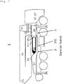
- figure 2 shows a truck-mounted concrete pump 1 known from the prior art, in which there is no diagonal reinforcement 213 between the legs 211, 212 and as a result the pivoting leg 2 must be made more massive, heavier and therefore more expensive in order to be able to withstand the same loads as in figure 1 shown vehicle according to the invention.
Description
Die Erfindung betrifft eine Autobetonpumpe mit wenigstens einem hinteren Schwenkbein und wenigstens einem vorderen Schwenkbein, wobei das vordere Schwenkbein einen Beinkasten und wenigstens einen dazu teleskopierbaren inneren Teil umfasst und wobei das hintere Schwenkbein ein äußeres Teil mit einem oberen und einem unteren Schenkel umfasst, zwischen denen der innere Teil des vorderen Schwenkbeins in einem einteleskopierbaren und eingeschwenkten Zustand lagerbar ist.The invention relates to a truck-mounted concrete pump with at least one rear pivoting leg and at least one front pivoting leg, the front pivoting leg comprising a leg box and at least one inner part that can be telescoped thereto, and the rear pivoting leg comprising an outer part with an upper and a lower leg, between which the inner part of the front swivel leg can be stored in a telescoping and swiveled-in state.
Aus dem Stand der Technik bekannte Autobetonpumpen umfassen üblicherweise Schwenkbeine zum Abstützen der Autobetonpumpe in einem Arbeitszustand. In dem Arbeitszustand der Autobetonpumpe kann ein Verteilermast der Autobetonpumpe ausgefahren sein und es kann mittels der Betonpumpe und dem Verteilermast Beton beispielsweise in einem Baustellenbereich ausgebracht werden. Die Schwenkbeine der Autobetonpumpe können je nach Bauart in unterschiedlichen Varianten angeordnet beziehungsweise kombiniert werden.State-of-the-art truck-mounted concrete pumps typically include pivoting legs for supporting the truck-mounted concrete pump in a working condition. In the working state of the truck-mounted concrete pump, a placing boom of the truck-mounted concrete pump can be extended and concrete can be placed in a construction site area, for example, by means of the concrete pump and the placing boom. Depending on the design, the swivel legs of the truck-mounted concrete pump can be arranged or combined in different ways.
Als Beispiel offenbart Dokument
Aufgrund der kompakten Bauweise benötigt ein eingefahrenes und eingeschwenktes vorderes Teleskopbein bzw. Schwenkbein einer Autobetonpumpe in einem Fahrzustand der Maschine üblicherweise Platz im hinteren Schwenkbein beziehungsweise Platz im Bereich einer Ausnehmung des hinteren Schwenkbeins. Der Platzbedarf hängt dabei von der Länge der Schwenkbeine und der Gestaltung des Mastbocks der Autobetonpumpe ab.Due to the compact design, a retracted and pivoted front telescopic leg or swivel leg of a truck-mounted concrete pump is required in one Driving condition of the machine usually space in the rear pivoting leg or space in the area of a recess in the rear pivoting leg. The space requirement depends on the length of the pivoting legs and the design of the truck-mounted concrete pump's mast bracket.
Aus diesem Grund weisen die hinteren Schwenkbeine aller Autobetonpumpen, die dem in der
Vor diesem Hintergrund ist es Aufgabe der Erfindung eine verbesserte Autobetonpumpe bereitzustellen, bei der insbesondere geringere Herstellungskosten und ein geringeres Bauteilgewicht erreicht werden, indem die Struktur der Schwenkbeine entsprechend verbessert wird.Against this background, the object of the invention is to provide an improved truck-mounted concrete pump in which, in particular, lower production costs and a lower component weight are achieved by correspondingly improving the structure of the pivoting legs.
Diese Aufgabe wird erfindungsgemäß durch eine Autobetonpumpe mit den Merkmalen des Anspruchs 1 gelöst. Vorteilhafte Ausgestaltungen sind Gegenstand der Unteransprüche.According to the invention, this object is achieved by a truck-mounted concrete pump with the features of
Demnach ist eine Autobetonpumpe mit wenigstens einem hinteren Schwenkbein und wenigstens einem vorderen Schwenkbein vorgesehen, wobei das vordere Schwenkbein einen Beinkasten und wenigstens einen dazu teleskopierbaren inneren Teil umfasst. Es ist auch denkbar, dass die Schwenkbeine mehrfach teleskopierbar ausgeführt sind.Accordingly, a truck-mounted concrete pump is provided with at least one rear pivoting leg and at least one front pivoting leg, the front Pivoting leg comprises a leg box and at least one inner part telescopic thereto. It is also conceivable that the pivoting legs are designed to be telescopic several times.
Das hintere Schwenkbein umfasst ein äußeres Teil mit einem oberen und einem unteren Schenkel, zwischen denen der innere Teil des vorderen Schwenkbeins in einem einteleskopierten und eingeschwenkten Zustand lagerbar ist. Erfindungsgemäß ist vorgesehen, dass die beiden Schenkel mittels wenigstens einer Diagonalaussteifung auf der Außerseite des hinteren Schwenkbeins miteinander gekoppelt sind. Erfindungsgemäß kann dabei selbstverständlich auch genau eine Diagonalaussteifung vorgesehen sein.The rear pivoting leg comprises an outer part with an upper and a lower leg between which the inner part of the front pivoting leg can be stored in a telescoped and pivoted state. According to the invention, it is provided that the two legs are coupled to one another by means of at least one diagonal reinforcement on the outside of the rear pivoting leg. According to the invention, exactly one diagonal bracing can of course also be provided.
Die der Erfindung zu Grunde liegende Idee besteht somit darin, den unteren Schenkel des hinteren Schwenkbeins auf dessen Außenseite von einem unteren Gelenkpunkt des hinteren Schwenkbeins diagonal mit dem beinseitigen Ende des oberen Schenkels zu verbinden und/oder in umgekehrter Richtung. Auf diese Art wird ein sehr tragfähiges, fachwerkartiges Dreieck erzeugt. Hierdurch kann das hintere Schwenkbein mit verhältnismäßig geringem Materialaufwand und damit gewicht- und kostensparend versteift werden. Die Außenseite des hinteren Schwenkbeins ist die Seite, die beim Abwinkeln der vorderen und hinteren Beine zueinander zum Abstützen der Maschine nicht vom Teleskopbein durchdrungen wird.The idea on which the invention is based is therefore to connect the lower leg of the rear pivoting leg on its outside diagonally from a lower hinge point of the rear pivoting leg to the leg-side end of the upper leg and/or in the opposite direction. In this way a very stable, truss-like triangle is created. As a result, the rear swivel leg can be stiffened with relatively little outlay on material and thus in a way that saves weight and costs. The outside of the rear swing leg is the side not penetrated by the telescopic leg when angling the front and rear legs toward each other to support the machine.
Dabei macht man sich den Umstand zunutze, dass Schwenkbeine mobiler Betonpumpen vorrangig in einer Richtung belastet werden. Eine Zugbelastung an der Unterseite des Schwenkbeins ist die vorherrschende Belastung im Pumpenbetrieb bzw. im Arbeitszustand der Autobetonpumpe. Durch die diagonale Aussteifung der Öffnung zwischen dem oberen und dem unteren Schenkel des hinteren Schwenkbeins wird insbesondere der untere Schenkel der Öffnung deutlich von Biegungen entlastet und der gesamte Öffnungsbereich kann damit vorteilhafterweise leichter ausgeführt werden.This takes advantage of the fact that the swivel legs of mobile concrete pumps are primarily loaded in one direction. A tensile load on the underside of the swivel leg is the predominant load in pump operation or in the working condition of the truck-mounted concrete pump. Due to the diagonal bracing of the opening between the upper and the lower leg of the rear swivel leg, the lower leg of the opening in particular is significantly relieved of bending and the entire opening area can thus advantageously be made lighter.
In einer bevorzugten Ausführung der Erfindung ist denkbar, dass die beiden Schenkel in Höhenrichtung wenigstens abschnittsweise oder über ihre gesamte Länge allein durch die Diagonalaussteifung gekoppelt sind. Dies bedeutet, dass in den beschriebenen Abschnitten des hinteren Schwenkbeins die Diagonalaussteifung die alleinige Verbindung der Schenkel ist und keine sonstigen Verbindungsmittel beziehungsweise Verbindungen vorgesehen sind. An den Schenkelenden kann selbstverständlich eine Schwenkachse vorgesehen sein, um die das Schwenkbein ist bzw. beide Schwenkbeine schwenkbar sind und die zwangsläufig eine weitere allerdings unterschiedliche Verbindungsart zwischen den beiden Schenkeln darstellt.In a preferred embodiment of the invention it is conceivable that the two legs in the height direction at least in sections or over their entirety Length are coupled solely by the diagonal bracing. This means that in the described sections of the rear pivoting leg, the diagonal bracing is the sole connection of the legs and no other connecting means or connections are provided. Of course, a pivot axis can be provided at the ends of the legs, about which the pivoting leg is or both pivoting legs can be pivoted and which inevitably represents a further, albeit different, type of connection between the two legs.
In einer weiteren bevorzugten Ausführung ist denkbar, dass sich die Diagonalaussteifung bis zu einem innersten Abschnitt eines der Schenkel erstreckt. Dieser innerste Abschnitt kann den Bereich des Schenkels umfassen, in welchem die Schwenkachse des Schenkels angeordnet ist und welcher der der Autobetonpumpe am nächsten angeordnete Bereich des Schwenkbeins ist.In a further preferred embodiment it is conceivable that the diagonal bracing extends to an innermost section of one of the legs. This innermost portion may include the portion of the leg in which the pivot axis of the leg is located and which is the portion of the pivot leg closest to the truck-mounted concrete pump.
In einer weiteren bevorzugten Ausführung ist denkbar, dass sich die Diagonalaussteifung bis zu einer Schwenkachse des hinteren Schwenkbeins erstreckt. Wie erwähnt kann die Schwenkachse im Bereich des innersten Abschnitts des Schwenkbeins angeordnet sein und dazu eingerichtet sein, das Schwenkbein relativ zur Autobetonpumpe zu verschwenken.In a further preferred embodiment it is conceivable that the diagonal bracing extends up to a pivot axis of the rear pivot leg. As mentioned, the pivot axis can be arranged in the area of the innermost section of the pivot leg and set up to pivot the pivot leg relative to the truck-mounted concrete pump.
In einer weiteren bevorzugten Ausführung ist denkbar, dass zwischen den Schenkeln eine U-förmige, dreieckige oder mehreckige Öffnung ausgebildet ist, die insbesondere nach außen hin offen ist. Somit kann zwischen den Schenkeln ein bogenförmiger oder eckiger Bereich den äußeren Teil der Öffnung bilden. Die Öffnung selbst kann dabei horizontal ausgerichtet sein, sodass der innere Teil des vorderen Schwenkbeins wenigstens teilweise in die Öffnung des hinteren Schwenkbeins einschiebbar ist. Bei einer U-förmigen Öffnung kann der Radius der Öffnung beispielsweise zwischen einem Vierte und der Hälfte der Höhe des hinteren Schwenkbeins betragen.In a further preferred embodiment, it is conceivable that a U-shaped, triangular or polygonal opening is formed between the legs, which is open in particular to the outside. Thus, between the legs, an arcuate or angular area can form the outer part of the opening. The opening itself can be aligned horizontally, so that the inner part of the front pivoting leg can be pushed at least partially into the opening of the rear pivoting leg. For example, with a U-shaped opening, the radius of the opening may be between one-fourth and one-half the height of the rear pivot leg.
In einer weiteren bevorzugten Ausführung ist denkbar, dass das innere Teil des vorderen Schwenkbeins in dessen einteleskopierten Zustand von den Schenkeln und der Diagonalaussteifung des hinteren Schwenkbeins eingefasst ist. Die Schenkel und die Diagonalaussteifung umfassen damit den inneren Teil des Schwenkbeins im einteleskopierten Zustand wenigstens teilweise. Der innere Teil des Schwenkbeins bzw. das innere teleskopierbare Teil kann dabei im einteleskopierten Zustand durch Ausnehmungen im Bereich des äußeren Teils von außen sichtbar sein.In a further preferred embodiment it is conceivable that the inner part of the front pivoting leg is framed by the legs and the diagonal bracing of the rear pivoting leg in its telescoped state. The legs and the diagonal bracing thus at least partially enclose the inner part of the pivoting leg in the telescoped-in state. The inner part of the swivel leg or the inner telescoping part can be visible from the outside in the telescoped state through recesses in the area of the outer part.
In einer weiteren bevorzugten Ausführung ist denkbar, dass die Diagonalaussteifung mindestens so lang wie der Abstand der beiden Schenkel und/oder höchstens doppelt so lang wie einer der Schenkel ist. In der kürzesten Ausführung ist die Diagonalaussteifung dabei gerade so lang, wie der Abstand der beiden Schenkel zueinander. Die Diagonalaussteifung kann damit senkrecht zu den Schenkeln angeordnet sein. Der Begriff der Diagonalaussteifung ist also nicht einschränkend zu verstehen. Es ist alternativ oder zusätzlich denkbar, dass sich die Diagonalaussteifung in Höhenrichtung mindestens halb und höchstens doppelt so weit erstreckt wie einer der Schenkel.In a further preferred embodiment it is conceivable that the diagonal bracing is at least as long as the distance between the two legs and/or at most twice as long as one of the legs. In the shortest version, the diagonal bracing is just as long as the distance between the two legs. The diagonal bracing can thus be arranged perpendicularly to the legs. The concept of diagonal bracing is therefore not to be understood as limiting. It is alternatively or additionally conceivable that the diagonal bracing extends at least half and at most twice as far in the height direction as one of the legs.
In einer weiteren bevorzugten Ausführung ist denkbar, dass die Diagonalaussteifung in ihrer Längsrichtung wenigstens teilweise ein gleichbleibendes Profil aufweist und/oder eine größere Länge als Breite aufweist. Damit kann die Diagonalaussteifung als insgesamt längliches Teil ausgebildet sein.In a further preferred embodiment, it is conceivable that the diagonal reinforcement has at least partially a constant profile in its longitudinal direction and/or has a greater length than width. The diagonal stiffener can thus be designed as a part that is elongated overall.
Es kann ferner vorgesehen sein, dass nicht nur eine einzige sondern wenigstens zwei Diagonalaussteifungen an dem hinteren Schwenkbein vorgesehen sind. Die Diagonalaussteifungen können an einander gegenüberliegenden Seiten des Schwenkbeins oder an derselben Seite des Schwenkbeins angeordnet sein.It can also be provided that not just a single but at least two diagonal stiffeners are provided on the rear swivel leg. The diagonal braces may be located on opposite sides of the pivot leg or on the same side of the pivot leg.
Weitere Einzelheiten und Vorteile der Erfindung sind anhand der in den Figuren beispielhaft gezeigten Ausführungen erläutert. Dabei zeigen:
- Figur 1:
- eine schematische Ansicht einer erfindungsgemäßen Autobetonpumpe; und
- Figur 2:
- eine schematische Ansicht einer aus dem Stand der Technik bekannten Betonpumpe.
- Figure 1:
- a schematic view of a truck-mounted concrete pump according to the invention; and
- Figure 2:
- a schematic view of a concrete pump known from the prior art.
Der Verteilermast 10 ist über einen Mastbock 11 mit dem restlichen Gefüge der Autobetonpumpe 1 gekoppelt. Die Autobetonpumpe gemäß
Die Autobetonpumpe 1 kann als Lastwagen 27 bzw. als Arbeitsgerät mit einer Fahrerkabine 27' ausgeführt sein.The truck-mounted
Die Autobetonpumpe 1 umfasst wenigstens ein hinteres Schwenkbein 2 mit einem äußeren Teil 21. Das vordere Schwenkbein 3 weist einen Beinkasten 26 auf, in dem ein inneres Teil 22 verschieblich bzw. teleskopierbar gelagert ist. Das äußere Teil 21 des hinteren Schwenkbeins 2 umfasst einen oberen Schenkel 211 und einen unteren Schenkel 212. Zwischen den beiden Schenkeln 211, 212 ist der innere Teil 22 des vorderen Schwenkbeins 3 in einem in
Erfindungsgemäß ist vorgesehen, dass die beiden Schenkel 211, 212 mittels wenigstens einer Diagonalaussteifung 213 miteinander gekoppelt sind.According to the invention, it is provided that the two
Die beiden Schenkel 211, 212 definieren gemeinsam mit einem abgerundeten oder eckigen Abschnitt eine Öffnung 24. Die beiden Schenkel 211, 212 verlaufen dabei in Längsrichtung des Schwenkbeins zwischen dem gebogenen oder eckigen Bereich der Öffnung 24 und der Schwenkachse 23. Die Schwenkachse 23 ist dazu eingerichtet, die Schwenkbeine 2, 3 relativ zur Autobetonpumpe 1 zu verschwenken. Es ist denkbar, dass beide Schwenkbeine 2, 3 über einen gemeinsamen Bolzen bzw. eine entsprechende gemeinsame Schwenkachse 23 relativ zum restlichen Gefüge der Autobetonpumpe 1 schwenkbar sind.The two
Die beiden Schenkel 211, 212 sind in Höhenrichtung beziehungsweise in der vertikalen Richtung in der in
Die Schenkel 211, 212 und/oder die Diagonalaussteifung 213 können einstückig miteinander beispielsweise als ausgebrannte Metallelemente bzw. als einzelnes Blech ausgeführt sein. Es können zusätzlich oder alternativ auch anderer Werkstoffe als Metalle Verwendung finden. Denkbar ist, dass die Diagonalaussteifung 213 beispielsweise als Strebe aus einem metallischen oder nichtmetallischen Werkstoff wie Faserverbundwerkstoff (z.B. auf Carbonbasis) gefertigt ist. Diese Strebe kann mit den Schenkeln 211, 212 verschraubt und/oder verbolzt sein und insbesondere zur Aufnahme von Zugbelastungen eingerichtet sein.The
Im Ausführungsbeispiel der
Bei einer Ausführung mit mehreren Diagonalaussteifungen 213 können diese gleich oder unterschiedlich zueinander verlaufen. So können mehrere Diagonalaussteifungen 213 parallel zueinander oder über Kreuz angeordnet sein und/oder an einander gegenüberliegenden Seiten des hinteren Schwenkbeins 2 vorgesehen sein. Die Aussteifungen können damit X- oder K-förmig ausgebildet sein.In an embodiment with a plurality of
Die Schwenkachse 23 ist in einem innersten Abschnitt der Schenkel 211, 212 angeordnet und die Diagonalaussteifung 213 kann sich bis zu diesem innersten Bereich erstrecken. Wie den Figuren zu entnehmen ist, erstreckt sich zwischen den beiden Schenkeln 211, 212 eine Öffnung 24, die von der Diagonalaussteifung 213 diagonal und teilweise abgedeckt ist.The
Wie
Ferner ist es denkbar, dass die spitzen Winkel 25 zwischen den Schenkeln 211, 212 und der Diagonalaussteifung 213 mit Verstärkungsmitteln gefüllt sind, welche die Belastung in den Bereichen dieser Winkel 25 reduzieren. Denkbar ist, dass die Übergangsbereiche der Diagonalaussteifung 213 zu den Schenkeln 211, 212 abgerundet bzw. mit Ausrundungen gefertigt sind, wodurch deren dynamische Belastung verringert werden kann.Furthermore, it is conceivable that the
Es ist auch denkbar mehr als eine Diagonalaussteifung 213 an dem Schwenkbein 2 vorzusehen, wobei die Diagonalaussteifungen 213 an einander gegenüberliegenden Seiten des Schwenkbeins 2 oder an derselben Seite des Schwenkbeins 2 angeordnet sein können.It is also conceivable to provide more than one
Claims (9)
- Truck-mounted concrete pump (1) comprising at least one rear pivotable leg (2) and at least one front pivotable leg (3), wherein the front pivotable leg (3) comprises a leg box (26) and at least one inner part (22) that is telescopic with respect thereto, and wherein the rear pivotable leg (2) comprises an outer part (21) having a upper (211) and a lower (212) limb, between which the inner part (22) of the front pivotable leg (3) can be mounted in a state telescoped and pivoted in, characterised in that the two limbs (211, 212) are coupled together by means of at least one diagonal bracing (213), wherein the lower limb (212) of the rear pivotable leg (2) is connected diagonally, on the outside thereof, by a lower articulation point of the rear pivotable leg (2), to the leg-side end of the upper limb (212), and/or in the reverse direction.
- Truck-mounted concrete pump (1) according to claim 1, characterised in that the two limbs (211, 212) are coupled in the height direction, at least in portions or over the entire length thereof, only by the diagonal bracing (213).
- Truck-mounted concrete pump (1) according to either of the preceding claims, characterised in that the diagonal bracing (213) extends as far as an innermost portion of one of the limbs (211, 212).
- Truck-mounted concrete pump (1) according to any of the preceding claims, characterised in that the diagonal bracing (213) extends as far as a swivel pin (23) of the rear pivotable leg (2).
- Truck-mounted concrete pump (1) according to any of the preceding claims, characterised in that a U-shaped, biangular, triangular or polygonal opening (24) is formed between the limbs (211, 212), which opening is in particular open towards the outside.
- Truck-mounted concrete pump (1) according to any of the preceding claims, characterised in that the inner part (22) of the front pivotable leg (3) is surrounded, in the telescoped-in state thereof, by the limbs (211, 212) and the diagonal bracing (213) of the rear pivotable leg (2).
- Truck-mounted concrete pump (1) according to any of the preceding claims, characterised in that the diagonal bracing (213) is at least as long as the spacing of the two limbs (211, 212) and/or at most twice as long as one of the limbs (211, 212).
- Truck-mounted concrete pump (1) according to any of the preceding claims, characterised in that the diagonal bracing (213) has a uniform profile, at least in part, in the longitudinal direction thereof, and/or is larger in length than in width.
- Truck-mounted concrete pump (1) according to any of the preceding claims, characterised in that at least two diagonal bracings (213) are provided on the rear pivotable leg (2).
Applications Claiming Priority (1)
| Application Number | Priority Date | Filing Date | Title |
|---|---|---|---|
| DE102018109223.7A DE102018109223A1 (en) | 2018-04-18 | 2018-04-18 | Concrete pump |
Publications (2)
| Publication Number | Publication Date |
|---|---|
| EP3556718A1 EP3556718A1 (en) | 2019-10-23 |
| EP3556718B1 true EP3556718B1 (en) | 2022-06-15 |
Family
ID=66175284
Family Applications (1)
| Application Number | Title | Priority Date | Filing Date |
|---|---|---|---|
| EP19169023.9A Active EP3556718B1 (en) | 2018-04-18 | 2019-04-12 | Concrete pump vehicle |
Country Status (3)
| Country | Link |
|---|---|
| EP (1) | EP3556718B1 (en) |
| DE (1) | DE102018109223A1 (en) |
| ES (1) | ES2926456T3 (en) |
Families Citing this family (2)
| Publication number | Priority date | Publication date | Assignee | Title |
|---|---|---|---|---|
| FR3102785B1 (en) | 2019-11-04 | 2021-10-08 | Quali Parts & Services | Concrete pump equipped with danger detection means |
| FR3106825B1 (en) | 2020-02-04 | 2022-04-08 | Quali Parts & Services | Concrete pump with concreting mast equipped with an electrical manifold and electrical manifold for such a mast |
Family Cites Families (7)
| Publication number | Priority date | Publication date | Assignee | Title |
|---|---|---|---|---|
| GB722703A (en) * | 1951-11-23 | 1955-01-26 | British Hoist And Crane Compan | Improvements in and relating to cranes |
| GB865102A (en) * | 1958-10-01 | 1961-04-12 | Shannon Kerr Clements | Attachments for supporting booms carried by vehicles |
| DE4344779C2 (en) * | 1993-12-28 | 1999-12-09 | Schwing Gmbh F | Vehicle with a swiveling mast and frame support |
| DE29811097U1 (en) | 1998-06-20 | 1998-08-20 | Waitzinger Baumaschinen Vertri | Mobile concrete pump |
| EP1351877B1 (en) * | 2001-01-18 | 2008-10-08 | KGW Förder- und Servicetechnik Gmbh | Lifting device |
| DE202007018214U1 (en) * | 2007-12-19 | 2008-07-10 | Waitzinger Baumaschinen Gmbh | Mobile concrete pump |
| DE102013205888A1 (en) * | 2013-04-03 | 2014-10-09 | Putzmeister Engineering Gmbh | Mobile working machine, in particular truck-mounted concrete pump and manufacturing process |
-
2018
- 2018-04-18 DE DE102018109223.7A patent/DE102018109223A1/en active Pending
-
2019
- 2019-04-12 EP EP19169023.9A patent/EP3556718B1/en active Active
- 2019-04-12 ES ES19169023T patent/ES2926456T3/en active Active
Also Published As
| Publication number | Publication date |
|---|---|
| DE102018109223A1 (en) | 2019-10-24 |
| EP3556718A1 (en) | 2019-10-23 |
| ES2926456T3 (en) | 2022-10-26 |
Similar Documents
| Publication | Publication Date | Title |
|---|---|---|
| EP2888422B1 (en) | Mobile concrete pump | |
| EP1477451B1 (en) | Uncoiling device for an extension jib of a mobile crane | |
| EP2640911B1 (en) | Mobile work appliance with a supporting structure | |
| DE2702243C2 (en) | ||
| DE202008004663U1 (en) | Lattice boom crane and lattice boom | |
| DE2346003C2 (en) | Telescopic crane boom | |
| DE102011115355B4 (en) | Boom element, telescopic boom and construction vehicle | |
| EP3556718B1 (en) | Concrete pump vehicle | |
| DE2254290A1 (en) | MOBILE, MOVABLE LOADING EQUIPMENT, PREFERABLY TOWER CRANES | |
| DE102013225228A1 (en) | Articulated mast, especially for stationary or mobile concrete pumps | |
| EP2772418B1 (en) | Means to widen a transport device, and transport device | |
| EP3290264B1 (en) | Conveyor trolley | |
| DE102015104139B4 (en) | Turntable for a large manipulator | |
| EP3477018A1 (en) | Hollow two point lever | |
| DE202010013544U1 (en) | Telescopic weft and crane with telescopic weft | |
| EP3157720B1 (en) | Truck mixer concrete pump | |
| DE102017001128B4 (en) | Support for a crane | |
| DE202013001898U1 (en) | Means for widening a means of transport and means of transport | |
| DE202004016639U1 (en) | mobile crane | |
| DE2639621A1 (en) | Mobile crane outrigger assembly - has two:section outriggers telescoped by rams with pivoting and retracting feet | |
| DE102019134637A1 (en) | Mobile crane | |
| DE102013003317B4 (en) | Means for widening a means of transport and means of transport | |
| EP4330493A1 (en) | Boom-arm segment for a concrete pump | |
| DE102012215767A1 (en) | Wall reinforcement component for board wall of transport container of load transport vehicle, has reinforcement structure connected with stiffening profile sections, and storage to store tilting cylinder for tilting container | |
| EP1084981A1 (en) | Articulated trussed beam with triangular section |
Legal Events
| Date | Code | Title | Description |
|---|---|---|---|
| PUAI | Public reference made under article 153(3) epc to a published international application that has entered the european phase |
Free format text: ORIGINAL CODE: 0009012 |
|
| STAA | Information on the status of an ep patent application or granted ep patent |
Free format text: STATUS: THE APPLICATION HAS BEEN PUBLISHED |
|
| AK | Designated contracting states |
Kind code of ref document: A1 Designated state(s): AL AT BE BG CH CY CZ DE DK EE ES FI FR GB GR HR HU IE IS IT LI LT LU LV MC MK MT NL NO PL PT RO RS SE SI SK SM TR |
|
| AX | Request for extension of the european patent |
Extension state: BA ME |
|
| RIN1 | Information on inventor provided before grant (corrected) |
Inventor name: BOGOLIUBOV, SERGII Inventor name: HABERKORN, RAINER |
|
| STAA | Information on the status of an ep patent application or granted ep patent |
Free format text: STATUS: REQUEST FOR EXAMINATION WAS MADE |
|
| 17P | Request for examination filed |
Effective date: 20200423 |
|
| RAP1 | Party data changed (applicant data changed or rights of an application transferred) |
Owner name: LIEBHERR-MISCHTECHNIK GMBH |
|
| GRAP | Despatch of communication of intention to grant a patent |
Free format text: ORIGINAL CODE: EPIDOSNIGR1 |
|
| STAA | Information on the status of an ep patent application or granted ep patent |
Free format text: STATUS: GRANT OF PATENT IS INTENDED |
|
| INTG | Intention to grant announced |
Effective date: 20220117 |
|
| GRAS | Grant fee paid |
Free format text: ORIGINAL CODE: EPIDOSNIGR3 |
|
| GRAA | (expected) grant |
Free format text: ORIGINAL CODE: 0009210 |
|
| STAA | Information on the status of an ep patent application or granted ep patent |
Free format text: STATUS: THE PATENT HAS BEEN GRANTED |
|
| AK | Designated contracting states |
Kind code of ref document: B1 Designated state(s): AL AT BE BG CH CY CZ DE DK EE ES FI FR GB GR HR HU IE IS IT LI LT LU LV MC MK MT NL NO PL PT RO RS SE SI SK SM TR |
|
| REG | Reference to a national code |
Ref country code: CH Ref legal event code: EP Ref country code: GB Ref legal event code: FG4D Free format text: NOT ENGLISH |
|
| REG | Reference to a national code |
Ref country code: IE Ref legal event code: FG4D Free format text: LANGUAGE OF EP DOCUMENT: GERMAN |
|
| REG | Reference to a national code |
Ref country code: DE Ref legal event code: R096 Ref document number: 502019004621 Country of ref document: DE |
|
| REG | Reference to a national code |
Ref country code: AT Ref legal event code: REF Ref document number: 1498292 Country of ref document: AT Kind code of ref document: T Effective date: 20220715 |
|
| REG | Reference to a national code |
Ref country code: LT Ref legal event code: MG9D |
|
| REG | Reference to a national code |
Ref country code: NL Ref legal event code: MP Effective date: 20220615 |
|
| REG | Reference to a national code |
Ref country code: ES Ref legal event code: FG2A Ref document number: 2926456 Country of ref document: ES Kind code of ref document: T3 Effective date: 20221026 |
|
| PG25 | Lapsed in a contracting state [announced via postgrant information from national office to epo] |
Ref country code: SE Free format text: LAPSE BECAUSE OF FAILURE TO SUBMIT A TRANSLATION OF THE DESCRIPTION OR TO PAY THE FEE WITHIN THE PRESCRIBED TIME-LIMIT Effective date: 20220615 Ref country code: NO Free format text: LAPSE BECAUSE OF FAILURE TO SUBMIT A TRANSLATION OF THE DESCRIPTION OR TO PAY THE FEE WITHIN THE PRESCRIBED TIME-LIMIT Effective date: 20220915 Ref country code: LT Free format text: LAPSE BECAUSE OF FAILURE TO SUBMIT A TRANSLATION OF THE DESCRIPTION OR TO PAY THE FEE WITHIN THE PRESCRIBED TIME-LIMIT Effective date: 20220615 Ref country code: HR Free format text: LAPSE BECAUSE OF FAILURE TO SUBMIT A TRANSLATION OF THE DESCRIPTION OR TO PAY THE FEE WITHIN THE PRESCRIBED TIME-LIMIT Effective date: 20220615 Ref country code: GR Free format text: LAPSE BECAUSE OF FAILURE TO SUBMIT A TRANSLATION OF THE DESCRIPTION OR TO PAY THE FEE WITHIN THE PRESCRIBED TIME-LIMIT Effective date: 20220916 Ref country code: FI Free format text: LAPSE BECAUSE OF FAILURE TO SUBMIT A TRANSLATION OF THE DESCRIPTION OR TO PAY THE FEE WITHIN THE PRESCRIBED TIME-LIMIT Effective date: 20220615 Ref country code: BG Free format text: LAPSE BECAUSE OF FAILURE TO SUBMIT A TRANSLATION OF THE DESCRIPTION OR TO PAY THE FEE WITHIN THE PRESCRIBED TIME-LIMIT Effective date: 20220915 |
|
| PG25 | Lapsed in a contracting state [announced via postgrant information from national office to epo] |
Ref country code: RS Free format text: LAPSE BECAUSE OF FAILURE TO SUBMIT A TRANSLATION OF THE DESCRIPTION OR TO PAY THE FEE WITHIN THE PRESCRIBED TIME-LIMIT Effective date: 20220615 Ref country code: LV Free format text: LAPSE BECAUSE OF FAILURE TO SUBMIT A TRANSLATION OF THE DESCRIPTION OR TO PAY THE FEE WITHIN THE PRESCRIBED TIME-LIMIT Effective date: 20220615 |
|
| PG25 | Lapsed in a contracting state [announced via postgrant information from national office to epo] |
Ref country code: NL Free format text: LAPSE BECAUSE OF FAILURE TO SUBMIT A TRANSLATION OF THE DESCRIPTION OR TO PAY THE FEE WITHIN THE PRESCRIBED TIME-LIMIT Effective date: 20220615 |
|
| PG25 | Lapsed in a contracting state [announced via postgrant information from national office to epo] |
Ref country code: SM Free format text: LAPSE BECAUSE OF FAILURE TO SUBMIT A TRANSLATION OF THE DESCRIPTION OR TO PAY THE FEE WITHIN THE PRESCRIBED TIME-LIMIT Effective date: 20220615 Ref country code: SK Free format text: LAPSE BECAUSE OF FAILURE TO SUBMIT A TRANSLATION OF THE DESCRIPTION OR TO PAY THE FEE WITHIN THE PRESCRIBED TIME-LIMIT Effective date: 20220615 Ref country code: RO Free format text: LAPSE BECAUSE OF FAILURE TO SUBMIT A TRANSLATION OF THE DESCRIPTION OR TO PAY THE FEE WITHIN THE PRESCRIBED TIME-LIMIT Effective date: 20220615 Ref country code: PT Free format text: LAPSE BECAUSE OF FAILURE TO SUBMIT A TRANSLATION OF THE DESCRIPTION OR TO PAY THE FEE WITHIN THE PRESCRIBED TIME-LIMIT Effective date: 20221017 Ref country code: EE Free format text: LAPSE BECAUSE OF FAILURE TO SUBMIT A TRANSLATION OF THE DESCRIPTION OR TO PAY THE FEE WITHIN THE PRESCRIBED TIME-LIMIT Effective date: 20220615 Ref country code: CZ Free format text: LAPSE BECAUSE OF FAILURE TO SUBMIT A TRANSLATION OF THE DESCRIPTION OR TO PAY THE FEE WITHIN THE PRESCRIBED TIME-LIMIT Effective date: 20220615 |
|
| PG25 | Lapsed in a contracting state [announced via postgrant information from national office to epo] |
Ref country code: PL Free format text: LAPSE BECAUSE OF FAILURE TO SUBMIT A TRANSLATION OF THE DESCRIPTION OR TO PAY THE FEE WITHIN THE PRESCRIBED TIME-LIMIT Effective date: 20220615 Ref country code: IS Free format text: LAPSE BECAUSE OF FAILURE TO SUBMIT A TRANSLATION OF THE DESCRIPTION OR TO PAY THE FEE WITHIN THE PRESCRIBED TIME-LIMIT Effective date: 20221015 |
|
| REG | Reference to a national code |
Ref country code: DE Ref legal event code: R097 Ref document number: 502019004621 Country of ref document: DE |
|
| PG25 | Lapsed in a contracting state [announced via postgrant information from national office to epo] |
Ref country code: AL Free format text: LAPSE BECAUSE OF FAILURE TO SUBMIT A TRANSLATION OF THE DESCRIPTION OR TO PAY THE FEE WITHIN THE PRESCRIBED TIME-LIMIT Effective date: 20220615 |
|
| PLBE | No opposition filed within time limit |
Free format text: ORIGINAL CODE: 0009261 |
|
| STAA | Information on the status of an ep patent application or granted ep patent |
Free format text: STATUS: NO OPPOSITION FILED WITHIN TIME LIMIT |
|
| PG25 | Lapsed in a contracting state [announced via postgrant information from national office to epo] |
Ref country code: DK Free format text: LAPSE BECAUSE OF FAILURE TO SUBMIT A TRANSLATION OF THE DESCRIPTION OR TO PAY THE FEE WITHIN THE PRESCRIBED TIME-LIMIT Effective date: 20220615 |
|
| 26N | No opposition filed |
Effective date: 20230316 |
|
| PG25 | Lapsed in a contracting state [announced via postgrant information from national office to epo] |
Ref country code: SI Free format text: LAPSE BECAUSE OF FAILURE TO SUBMIT A TRANSLATION OF THE DESCRIPTION OR TO PAY THE FEE WITHIN THE PRESCRIBED TIME-LIMIT Effective date: 20220615 |
|
| P01 | Opt-out of the competence of the unified patent court (upc) registered |
Effective date: 20230530 |
|
| PGFP | Annual fee paid to national office [announced via postgrant information from national office to epo] |
Ref country code: IT Payment date: 20230428 Year of fee payment: 5 Ref country code: FR Payment date: 20230425 Year of fee payment: 5 Ref country code: ES Payment date: 20230503 Year of fee payment: 5 Ref country code: DE Payment date: 20230426 Year of fee payment: 5 Ref country code: CH Payment date: 20230502 Year of fee payment: 5 |
|
| PGFP | Annual fee paid to national office [announced via postgrant information from national office to epo] |
Ref country code: TR Payment date: 20230406 Year of fee payment: 5 |
|
| GBPC | Gb: european patent ceased through non-payment of renewal fee |
Effective date: 20230412 |
|
| PG25 | Lapsed in a contracting state [announced via postgrant information from national office to epo] |
Ref country code: LU Free format text: LAPSE BECAUSE OF NON-PAYMENT OF DUE FEES Effective date: 20230412 |
|
| REG | Reference to a national code |
Ref country code: BE Ref legal event code: MM Effective date: 20230430 |
|
| PG25 | Lapsed in a contracting state [announced via postgrant information from national office to epo] |
Ref country code: MC Free format text: LAPSE BECAUSE OF FAILURE TO SUBMIT A TRANSLATION OF THE DESCRIPTION OR TO PAY THE FEE WITHIN THE PRESCRIBED TIME-LIMIT Effective date: 20220615 |
|
| PG25 | Lapsed in a contracting state [announced via postgrant information from national office to epo] |
Ref country code: GB Free format text: LAPSE BECAUSE OF NON-PAYMENT OF DUE FEES Effective date: 20230412 |
|
| PG25 | Lapsed in a contracting state [announced via postgrant information from national office to epo] |
Ref country code: MC Free format text: LAPSE BECAUSE OF FAILURE TO SUBMIT A TRANSLATION OF THE DESCRIPTION OR TO PAY THE FEE WITHIN THE PRESCRIBED TIME-LIMIT Effective date: 20220615 Ref country code: GB Free format text: LAPSE BECAUSE OF NON-PAYMENT OF DUE FEES Effective date: 20230412 |
|
| REG | Reference to a national code |
Ref country code: IE Ref legal event code: MM4A |
|
| PG25 | Lapsed in a contracting state [announced via postgrant information from national office to epo] |
Ref country code: BE Free format text: LAPSE BECAUSE OF NON-PAYMENT OF DUE FEES Effective date: 20230430 |
|
| PG25 | Lapsed in a contracting state [announced via postgrant information from national office to epo] |
Ref country code: IE Free format text: LAPSE BECAUSE OF NON-PAYMENT OF DUE FEES Effective date: 20230412 |