EP3556718B1 - Vehicule de pompe à béton - Google Patents
Vehicule de pompe à béton Download PDFInfo
- Publication number
- EP3556718B1 EP3556718B1 EP19169023.9A EP19169023A EP3556718B1 EP 3556718 B1 EP3556718 B1 EP 3556718B1 EP 19169023 A EP19169023 A EP 19169023A EP 3556718 B1 EP3556718 B1 EP 3556718B1
- Authority
- EP
- European Patent Office
- Prior art keywords
- leg
- truck
- concrete pump
- mounted concrete
- legs
- Prior art date
- Legal status (The legal status is an assumption and is not a legal conclusion. Google has not performed a legal analysis and makes no representation as to the accuracy of the status listed.)
- Active
Links
- 210000003414 extremity Anatomy 0.000 claims 8
- 210000003141 lower extremity Anatomy 0.000 claims 1
- 210000001364 upper extremity Anatomy 0.000 claims 1
- 230000002787 reinforcement Effects 0.000 description 12
- 239000003351 stiffener Substances 0.000 description 10
- 239000000463 material Substances 0.000 description 4
- 238000005452 bending Methods 0.000 description 2
- 238000004519 manufacturing process Methods 0.000 description 2
- 229910052751 metal Inorganic materials 0.000 description 2
- OKTJSMMVPCPJKN-UHFFFAOYSA-N Carbon Chemical compound [C] OKTJSMMVPCPJKN-UHFFFAOYSA-N 0.000 description 1
- 229910000831 Steel Inorganic materials 0.000 description 1
- 230000001154 acute effect Effects 0.000 description 1
- 108010081181 calcium-binding protein (brain) Proteins 0.000 description 1
- 229910052799 carbon Inorganic materials 0.000 description 1
- 239000002131 composite material Substances 0.000 description 1
- 238000010276 construction Methods 0.000 description 1
- 230000008878 coupling Effects 0.000 description 1
- 238000010168 coupling process Methods 0.000 description 1
- 238000005859 coupling reaction Methods 0.000 description 1
- 230000001419 dependent effect Effects 0.000 description 1
- 239000000835 fiber Substances 0.000 description 1
- 239000002184 metal Substances 0.000 description 1
- 239000007769 metal material Substances 0.000 description 1
- 150000002739 metals Chemical class 0.000 description 1
- 238000005086 pumping Methods 0.000 description 1
- 230000003014 reinforcing effect Effects 0.000 description 1
- 239000010959 steel Substances 0.000 description 1
- 230000007704 transition Effects 0.000 description 1
Images
Classifications
-
- B—PERFORMING OPERATIONS; TRANSPORTING
- B66—HOISTING; LIFTING; HAULING
- B66C—CRANES; LOAD-ENGAGING ELEMENTS OR DEVICES FOR CRANES, CAPSTANS, WINCHES, OR TACKLES
- B66C23/00—Cranes comprising essentially a beam, boom, or triangular structure acting as a cantilever and mounted for translatory of swinging movements in vertical or horizontal planes or a combination of such movements, e.g. jib-cranes, derricks, tower cranes
- B66C23/62—Constructional features or details
- B66C23/72—Counterweights or supports for balancing lifting couples
- B66C23/78—Supports, e.g. outriggers, for mobile cranes
-
- E—FIXED CONSTRUCTIONS
- E04—BUILDING
- E04G—SCAFFOLDING; FORMS; SHUTTERING; BUILDING IMPLEMENTS OR AIDS, OR THEIR USE; HANDLING BUILDING MATERIALS ON THE SITE; REPAIRING, BREAKING-UP OR OTHER WORK ON EXISTING BUILDINGS
- E04G21/00—Preparing, conveying, or working-up building materials or building elements in situ; Other devices or measures for constructional work
- E04G21/02—Conveying or working-up concrete or similar masses able to be heaped or cast
- E04G21/04—Devices for both conveying and distributing
- E04G21/0418—Devices for both conveying and distributing with distribution hose
- E04G21/0436—Devices for both conveying and distributing with distribution hose on a mobile support, e.g. truck
Definitions
- the invention relates to a truck-mounted concrete pump with at least one rear pivoting leg and at least one front pivoting leg, the front pivoting leg comprising a leg box and at least one inner part that can be telescoped thereto, and the rear pivoting leg comprising an outer part with an upper and a lower leg, between which the inner part of the front swivel leg can be stored in a telescoping and swiveled-in state.
- State-of-the-art truck-mounted concrete pumps typically include pivoting legs for supporting the truck-mounted concrete pump in a working condition.
- a placing boom of the truck-mounted concrete pump can be extended and concrete can be placed in a construction site area, for example, by means of the concrete pump and the placing boom.
- the swivel legs of the truck-mounted concrete pump can be arranged or combined in different ways.
- a retracted and pivoted front telescopic leg or swivel leg of a truck-mounted concrete pump is required in one Driving condition of the machine usually space in the rear pivoting leg or space in the area of a recess in the rear pivoting leg.
- the space requirement depends on the length of the pivoting legs and the design of the truck-mounted concrete pump's mast bracket.
- the rear swivel legs of all truck-mounted concrete pumps that are similar to those in the EP 1 090 195 B1 correspond to the type shown, in the joint areas very long, openings.
- the two legs of the opening act as a bending beam when the corresponding pivot leg is loaded.
- This opening proves to be unfavorable for dissipating the loads of the placing boom acting on the rear swivel legs during pumping operation into the subsoil, since the load-bearing cross-sections in the area of the opening can only have very small cross-sections for geometric reasons, which is caused by comparatively large wall thicknesses in the corresponding areas must be balanced.
- the object of the invention is to provide an improved truck-mounted concrete pump in which, in particular, lower production costs and a lower component weight are achieved by correspondingly improving the structure of the pivoting legs.
- a truck-mounted concrete pump is provided with at least one rear pivoting leg and at least one front pivoting leg, the front Pivoting leg comprises a leg box and at least one inner part telescopic thereto. It is also conceivable that the pivoting legs are designed to be telescopic several times.
- the rear pivoting leg comprises an outer part with an upper and a lower leg between which the inner part of the front pivoting leg can be stored in a telescoped and pivoted state. According to the invention, it is provided that the two legs are coupled to one another by means of at least one diagonal reinforcement on the outside of the rear pivoting leg. According to the invention, exactly one diagonal bracing can of course also be provided.
- the idea on which the invention is based is therefore to connect the lower leg of the rear pivoting leg on its outside diagonally from a lower hinge point of the rear pivoting leg to the leg-side end of the upper leg and/or in the opposite direction. In this way a very stable, truss-like triangle is created. As a result, the rear swivel leg can be stiffened with relatively little outlay on material and thus in a way that saves weight and costs.
- the outside of the rear swing leg is the side not penetrated by the telescopic leg when angling the front and rear legs toward each other to support the machine.
- the two legs in the height direction at least in sections or over their entirety Length are coupled solely by the diagonal bracing.
- the diagonal bracing is the sole connection of the legs and no other connecting means or connections are provided.
- a pivot axis can be provided at the ends of the legs, about which the pivoting leg is or both pivoting legs can be pivoted and which inevitably represents a further, albeit different, type of connection between the two legs.
- the diagonal bracing extends to an innermost section of one of the legs.
- This innermost portion may include the portion of the leg in which the pivot axis of the leg is located and which is the portion of the pivot leg closest to the truck-mounted concrete pump.
- the diagonal bracing extends up to a pivot axis of the rear pivot leg.
- the pivot axis can be arranged in the area of the innermost section of the pivot leg and set up to pivot the pivot leg relative to the truck-mounted concrete pump.
- a U-shaped, triangular or polygonal opening is formed between the legs, which is open in particular to the outside.
- an arcuate or angular area can form the outer part of the opening.
- the opening itself can be aligned horizontally, so that the inner part of the front pivoting leg can be pushed at least partially into the opening of the rear pivoting leg.
- the radius of the opening may be between one-fourth and one-half the height of the rear pivot leg.
- the inner part of the front pivoting leg is framed by the legs and the diagonal bracing of the rear pivoting leg in its telescoped state.
- the legs and the diagonal bracing thus at least partially enclose the inner part of the pivoting leg in the telescoped-in state.
- the inner part of the swivel leg or the inner telescoping part can be visible from the outside in the telescoped state through recesses in the area of the outer part.
- the diagonal bracing is at least as long as the distance between the two legs and/or at most twice as long as one of the legs. In the shortest version, the diagonal bracing is just as long as the distance between the two legs. The diagonal bracing can thus be arranged perpendicularly to the legs. The concept of diagonal bracing is therefore not to be understood as limiting. It is alternatively or additionally conceivable that the diagonal bracing extends at least half and at most twice as far in the height direction as one of the legs.
- the diagonal reinforcement has at least partially a constant profile in its longitudinal direction and/or has a greater length than width.
- the diagonal stiffener can thus be designed as a part that is elongated overall.
- diagonal stiffeners are provided on the rear swivel leg.
- the diagonal braces may be located on opposite sides of the pivot leg or on the same side of the pivot leg.
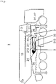
- figure 1 shows a truck-mounted concrete pump 1 according to the invention with a placing boom 10, via which concrete can be transported or pumped from a concrete mixer to a placement site.
- the placing boom 10 is coupled to the rest of the structure of the truck-mounted concrete pump 1 via a boom bracket 11 .
- the truck-mounted concrete pump according to figure 1 comprises two front pivoting legs 3 and two rear pivoting legs 2, the front pivoting legs 3 being able to comprise an in particular closed leg box 26.
- a front swivel leg 3 and a rear swivel leg 2 of the right side of the truck-mounted concrete pump 1 are shown.
- the truck-mounted concrete pump 1 can be designed as a truck 27 or as a working device with a driver's cab 27'.
- the truck-mounted concrete pump 1 comprises at least one rear pivoting leg 2 with an outer part 21.
- the front pivoting leg 3 has a leg box 26 in which an inner part 22 is slidably or telescopically mounted.
- the outer part 21 of the rear pivoting leg 2 comprises an upper leg 211 and a lower leg 212. Between the two legs 211, 212, the inner part 22 of the front pivoting leg 3 is in a figure 1 Can be stored in the telescoped and pivoted-in state shown.
- the inner part 22 of the front swivel leg 3 can also be referred to as a telescopic leg 22 .
- the two legs 211, 212 are coupled to one another by means of at least one diagonal stiffener 213.
- the two legs 211, 212 define an opening 24 together with a rounded or angular section.
- the two legs 211, 212 run in the longitudinal direction of the pivoting leg between the curved or angular area of the opening 24 and the pivot axis 23.
- the pivot axis 23 is set up for this purpose to pivot the pivoting legs 2, 3 relative to the truck-mounted concrete pump 1. It is conceivable that both pivoting legs 2, 3 can be pivoted relative to the rest of the structure of the truck-mounted concrete pump 1 via a common bolt or a corresponding common pivot axis 23.
- the two legs 211, 212 are in the height direction or in the vertical direction in the figure 1 shown embodiment coupled over its entire length solely by the diagonal brace 213. Only the pivot axis 23, which is arranged in the innermost area of the pivot leg 2, can be regarded as an additional coupling.
- the pivot axis 23 can be made movable relative to the components of the pivot leg 2 mentioned, while the legs 211, 212 and the diagonal reinforcement 213 can be made in one piece and/or cannot be adjusted relative to one another or can be rigid. It is conceivable to provide or cover the side area or intermediate space defined by the legs 211, 212 together with the diagonal reinforcement 213 with a cover plate.
- the legs 211, 212 and/or the diagonal stiffener 213 can be designed in one piece with one another, for example as burnt-out metal elements or as a single sheet. In addition or as an alternative, materials other than metals can also be used. It is conceivable that the diagonal reinforcement 213 is produced, for example, as a strut made of a metallic or non-metallic material such as a fiber composite material (eg based on carbon). This strut can be screwed and/or bolted to the legs 211, 212 and be set up in particular to absorb tensile loads.
- the diagonal stiffener 213 runs from the outside above, that is to say in the figure at the top left, to the inside below, that is to say in the figure at the bottom right. This results in a Z- or S-shaped stiffening.
- An alternative or additional reverse arrangement of the diagonal bracing is also conceivable.
- the diagonal bracing 213 can run on a single side of the rear pivoting leg 2 so that the diagonal bracing 213 cannot collide with the inner part 22 of the front pivoting leg 3 .
- diagonal reinforcements 213 these can run in the same way or differently from one another.
- several diagonal reinforcements 213 can be arranged parallel to one another or crossed and/or can be provided on opposite sides of the rear pivoting leg 2 .
- the reinforcements can thus be X-shaped or K-shaped.
- the pivot axis 23 is arranged in an innermost portion of the legs 211, 212 and the diagonal stiffener 213 can extend to this innermost region. As can be seen from the figures, an opening 24 extends between the two legs 211, 212, which is diagonally and partially covered by the diagonal reinforcement 213.
- the inner part 22 of the front pivoting leg 3 in the telescoped state shown therein can be bordered by the legs 211, 212 at the top and bottom and by the diagonal reinforcement 213 and/or guided therein. It can also be seen that the legs 211, 212 and the diagonal stiffener 213 extend approximately the same distance in the vertical direction or in the height direction, or that the components mentioned are manufactured to approximately the same thickness in the vertical direction.
- the acute angles 25 between the legs 211, 212 and the diagonal stiffener 213 are filled with reinforcing means which reduce the stress in the areas of these angles 25. It is conceivable that the transition areas of the diagonal reinforcement 213 to the legs 211, 212 are rounded or are made with fillets, whereby their dynamic load can be reduced.
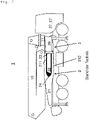
- figure 2 shows a truck-mounted concrete pump 1 known from the prior art, in which there is no diagonal reinforcement 213 between the legs 211, 212 and as a result the pivoting leg 2 must be made more massive, heavier and therefore more expensive in order to be able to withstand the same loads as in figure 1 shown vehicle according to the invention.
Claims (9)
- Pompe à béton automotrice (1) avec au moins une béquille arrière (2) et au moins une béquille avant (3), dans laquelle la béquille avant (3) comprend une boîte à béquille (26) et au moins une partie intérieure (22) télescopique par rapport à celle-ci et dans laquelle la béquille arrière (2) comprend une partie extérieure (21) avec une branche supérieure (211) et une branche inférieure (212), entre lesquelles la partie intérieure (22) de la béquille avant (3) peut être montée dans un état rentré de manière télescopique et rentrée par pivotement, caractérisée en ce que les deux branches (211, 212) sont couplées l'une à l'autre au moyen d'au moins un renfort diagonal (213), dans laquelle la branche inférieure (212) de la béquille arrière (2) est reliée, sur son côté extérieur, de manière diagonale à l'extrémité côté béquille de la branche supérieure (212) et/ou dans le sens inverse par un point d'articulation inférieur de la béquille arrière (2).
- Pompe à béton automotrice (1) selon la revendication 1, caractérisée en ce que les deux branches (211, 212) sont couplées dans le sens de la hauteur au moins par endroits ou sur la totalité de leur longueur seulement par le renfort diagonal (213).
- Pompe à béton automotrice (1) selon l'une quelconque des revendications précédentes, caractérisée en ce que le renfort diagonal (213) s'étend jusqu'à une section la plus intérieure d'une des branches (211, 212).
- Pompe à béton automotrice (1) selon l'une quelconque des revendications précédentes, caractérisée en ce que le renfort diagonal (213) s'étend jusqu'à un axe de pivotement (23) de la béquille arrière (2).
- Pompe à béton automotrice (1) selon l'une quelconque des revendications précédentes, caractérisée en ce qu'est réalisée entre les branches (211, 212) une ouverture (24) en forme de U à deux angles, à trois angles ou à angles multiples, qui est ouverte en particulier vers l'extérieur.
- Pompe à béton automotrice (1) selon l'une quelconque des revendications précédentes, caractérisée en ce que la partie intérieure (22) de la béquille avant (3) est encadrée, dans son état rentré de manière télescopique, par les branches (211, 212) et le renfort diagonal (213) de la béquille arrière (2).
- Pompe à béton automotrice (1) selon l'une quelconque des revendications précédentes, caractérisée en ce que le renfort diagonal (213) est au moins aussi long que la distance des deux branches (211, 212) et/ou est deux fois plus grand au maximum qu'une des branches (211, 212).
- Pompe à béton automotrice (1) selon l'une quelconque des revendications précédentes, caractérisée en ce que le renfort diagonal (213) présente dans son sens longitudinal au moins en partie un profil constant et/ou une longueur plus grande que la largeur.
- Pompe à béton automotrice (1) selon l'une quelconque des revendications précédentes, caractérisée en ce qu'au moins deux renforts diagonaux (213) sont prévus sur la béquille arrière (2).
Applications Claiming Priority (1)
| Application Number | Priority Date | Filing Date | Title |
|---|---|---|---|
| DE102018109223.7A DE102018109223A1 (de) | 2018-04-18 | 2018-04-18 | Autobetonpumpe |
Publications (2)
| Publication Number | Publication Date |
|---|---|
| EP3556718A1 EP3556718A1 (fr) | 2019-10-23 |
| EP3556718B1 true EP3556718B1 (fr) | 2022-06-15 |
Family
ID=66175284
Family Applications (1)
| Application Number | Title | Priority Date | Filing Date |
|---|---|---|---|
| EP19169023.9A Active EP3556718B1 (fr) | 2018-04-18 | 2019-04-12 | Vehicule de pompe à béton |
Country Status (3)
| Country | Link |
|---|---|
| EP (1) | EP3556718B1 (fr) |
| DE (1) | DE102018109223A1 (fr) |
| ES (1) | ES2926456T3 (fr) |
Families Citing this family (2)
| Publication number | Priority date | Publication date | Assignee | Title |
|---|---|---|---|---|
| FR3102785B1 (fr) | 2019-11-04 | 2021-10-08 | Quali Parts & Services | Pompe à béton équipée de moyens de détection de dangers |
| FR3106825B1 (fr) | 2020-02-04 | 2022-04-08 | Quali Parts & Services | Pompe à béton à mât de bétonnage équipé d’un collecteur électrique et collecteur électrique pour un tel mât |
Family Cites Families (7)
| Publication number | Priority date | Publication date | Assignee | Title |
|---|---|---|---|---|
| GB722703A (en) * | 1951-11-23 | 1955-01-26 | British Hoist And Crane Compan | Improvements in and relating to cranes |
| GB865102A (en) * | 1958-10-01 | 1961-04-12 | Shannon Kerr Clements | Attachments for supporting booms carried by vehicles |
| DE4344779C2 (de) * | 1993-12-28 | 1999-12-09 | Schwing Gmbh F | Fahrzeug mit schwenkbar aufgebautem Mast und Rahmenabstützung |
| DE29811097U1 (de) | 1998-06-20 | 1998-08-20 | Waitzinger Baumaschinen Vertri | Fahrbare Betonpumpe |
| US20030168871A1 (en) * | 2001-01-18 | 2003-09-11 | Gerhard Geis | Lifting device |
| DE202007018214U1 (de) * | 2007-12-19 | 2008-07-10 | Waitzinger Baumaschinen Gmbh | Fahrbare Betonpumpe |
| DE102013205888A1 (de) * | 2013-04-03 | 2014-10-09 | Putzmeister Engineering Gmbh | Fahrbare Arbeitsmaschine, insbesondere Autobetonpumpe und Herstellungsverfahren |
-
2018
- 2018-04-18 DE DE102018109223.7A patent/DE102018109223A1/de active Pending
-
2019
- 2019-04-12 ES ES19169023T patent/ES2926456T3/es active Active
- 2019-04-12 EP EP19169023.9A patent/EP3556718B1/fr active Active
Also Published As
| Publication number | Publication date |
|---|---|
| DE102018109223A1 (de) | 2019-10-24 |
| EP3556718A1 (fr) | 2019-10-23 |
| ES2926456T3 (es) | 2022-10-26 |
Similar Documents
| Publication | Publication Date | Title |
|---|---|---|
| EP2888422B1 (fr) | Pompe a beton mobile | |
| EP1477451B1 (fr) | Dispositif de déroulement pour une flèchette de grue mobile | |
| EP2640911B1 (fr) | Engin de travail mobile avec construction de soutien | |
| DE202008004663U1 (de) | Gittermastkran und Gittermastausleger | |
| DE2702243C2 (fr) | ||
| DE2346003C2 (de) | Teleskop-Kranausleger | |
| DE102011115355B4 (de) | Auslegerelement, Teleskopausleger sowie Baufahrzeug | |
| EP3556718B1 (fr) | Vehicule de pompe à béton | |
| DE2254290A1 (de) | Fahrbare, bewegliche belastungsmittel, vorzugsweise turmkraene | |
| DE102013225228A1 (de) | Knickmast, insbesondere für stationäre oder mobile Betonpumpen | |
| EP2772418B1 (fr) | Dispositif pour élargir un moyen de transport et moyen de transport | |
| EP3290264B1 (fr) | Chariot de transport | |
| DE102015104139B4 (de) | Drehschemel für einen Großmanipulator | |
| EP3477018A1 (fr) | Levier creux à deux points | |
| DE202010013544U1 (de) | Teleskopschuß und Kran mit Teleskopschuß | |
| EP3157720B1 (fr) | Camion mixo-pompe | |
| DE102017001128B4 (de) | Abstützung für einen Kran | |
| DE202013001898U1 (de) | Mittel zur Verbreiterung eines Transportmittels sowie Transportmittel | |
| DE2535948A1 (de) | Industriekran | |
| DE202004016639U1 (de) | Mobilkran | |
| DE2639621A1 (de) | Stuetzauslegeranordnung fuer einen fahrzeugkran | |
| DE102019134637A1 (de) | Fahrzeugkran | |
| DE102013003317B4 (de) | Mittel zur Verbreiterung eines Transportmittels sowie Transportmittel | |
| EP4330493A1 (fr) | Segment de bras de flèche destiné à une pompe à béton | |
| DE102012215767A1 (de) | Stirnwandbauteil mit integrierter Stirnwandstütze und Pressenlageraufnahme |
Legal Events
| Date | Code | Title | Description |
|---|---|---|---|
| PUAI | Public reference made under article 153(3) epc to a published international application that has entered the european phase |
Free format text: ORIGINAL CODE: 0009012 |
|
| STAA | Information on the status of an ep patent application or granted ep patent |
Free format text: STATUS: THE APPLICATION HAS BEEN PUBLISHED |
|
| AK | Designated contracting states |
Kind code of ref document: A1 Designated state(s): AL AT BE BG CH CY CZ DE DK EE ES FI FR GB GR HR HU IE IS IT LI LT LU LV MC MK MT NL NO PL PT RO RS SE SI SK SM TR |
|
| AX | Request for extension of the european patent |
Extension state: BA ME |
|
| RIN1 | Information on inventor provided before grant (corrected) |
Inventor name: BOGOLIUBOV, SERGII Inventor name: HABERKORN, RAINER |
|
| STAA | Information on the status of an ep patent application or granted ep patent |
Free format text: STATUS: REQUEST FOR EXAMINATION WAS MADE |
|
| 17P | Request for examination filed |
Effective date: 20200423 |
|
| RAP1 | Party data changed (applicant data changed or rights of an application transferred) |
Owner name: LIEBHERR-MISCHTECHNIK GMBH |
|
| GRAP | Despatch of communication of intention to grant a patent |
Free format text: ORIGINAL CODE: EPIDOSNIGR1 |
|
| STAA | Information on the status of an ep patent application or granted ep patent |
Free format text: STATUS: GRANT OF PATENT IS INTENDED |
|
| INTG | Intention to grant announced |
Effective date: 20220117 |
|
| GRAS | Grant fee paid |
Free format text: ORIGINAL CODE: EPIDOSNIGR3 |
|
| GRAA | (expected) grant |
Free format text: ORIGINAL CODE: 0009210 |
|
| STAA | Information on the status of an ep patent application or granted ep patent |
Free format text: STATUS: THE PATENT HAS BEEN GRANTED |
|
| AK | Designated contracting states |
Kind code of ref document: B1 Designated state(s): AL AT BE BG CH CY CZ DE DK EE ES FI FR GB GR HR HU IE IS IT LI LT LU LV MC MK MT NL NO PL PT RO RS SE SI SK SM TR |
|
| REG | Reference to a national code |
Ref country code: CH Ref legal event code: EP Ref country code: GB Ref legal event code: FG4D Free format text: NOT ENGLISH |
|
| REG | Reference to a national code |
Ref country code: IE Ref legal event code: FG4D Free format text: LANGUAGE OF EP DOCUMENT: GERMAN |
|
| REG | Reference to a national code |
Ref country code: DE Ref legal event code: R096 Ref document number: 502019004621 Country of ref document: DE |
|
| REG | Reference to a national code |
Ref country code: AT Ref legal event code: REF Ref document number: 1498292 Country of ref document: AT Kind code of ref document: T Effective date: 20220715 |
|
| REG | Reference to a national code |
Ref country code: LT Ref legal event code: MG9D |
|
| REG | Reference to a national code |
Ref country code: NL Ref legal event code: MP Effective date: 20220615 |
|
| REG | Reference to a national code |
Ref country code: ES Ref legal event code: FG2A Ref document number: 2926456 Country of ref document: ES Kind code of ref document: T3 Effective date: 20221026 |
|
| PG25 | Lapsed in a contracting state [announced via postgrant information from national office to epo] |
Ref country code: SE Free format text: LAPSE BECAUSE OF FAILURE TO SUBMIT A TRANSLATION OF THE DESCRIPTION OR TO PAY THE FEE WITHIN THE PRESCRIBED TIME-LIMIT Effective date: 20220615 Ref country code: NO Free format text: LAPSE BECAUSE OF FAILURE TO SUBMIT A TRANSLATION OF THE DESCRIPTION OR TO PAY THE FEE WITHIN THE PRESCRIBED TIME-LIMIT Effective date: 20220915 Ref country code: LT Free format text: LAPSE BECAUSE OF FAILURE TO SUBMIT A TRANSLATION OF THE DESCRIPTION OR TO PAY THE FEE WITHIN THE PRESCRIBED TIME-LIMIT Effective date: 20220615 Ref country code: HR Free format text: LAPSE BECAUSE OF FAILURE TO SUBMIT A TRANSLATION OF THE DESCRIPTION OR TO PAY THE FEE WITHIN THE PRESCRIBED TIME-LIMIT Effective date: 20220615 Ref country code: GR Free format text: LAPSE BECAUSE OF FAILURE TO SUBMIT A TRANSLATION OF THE DESCRIPTION OR TO PAY THE FEE WITHIN THE PRESCRIBED TIME-LIMIT Effective date: 20220916 Ref country code: FI Free format text: LAPSE BECAUSE OF FAILURE TO SUBMIT A TRANSLATION OF THE DESCRIPTION OR TO PAY THE FEE WITHIN THE PRESCRIBED TIME-LIMIT Effective date: 20220615 Ref country code: BG Free format text: LAPSE BECAUSE OF FAILURE TO SUBMIT A TRANSLATION OF THE DESCRIPTION OR TO PAY THE FEE WITHIN THE PRESCRIBED TIME-LIMIT Effective date: 20220915 |
|
| PG25 | Lapsed in a contracting state [announced via postgrant information from national office to epo] |
Ref country code: RS Free format text: LAPSE BECAUSE OF FAILURE TO SUBMIT A TRANSLATION OF THE DESCRIPTION OR TO PAY THE FEE WITHIN THE PRESCRIBED TIME-LIMIT Effective date: 20220615 Ref country code: LV Free format text: LAPSE BECAUSE OF FAILURE TO SUBMIT A TRANSLATION OF THE DESCRIPTION OR TO PAY THE FEE WITHIN THE PRESCRIBED TIME-LIMIT Effective date: 20220615 |
|
| PG25 | Lapsed in a contracting state [announced via postgrant information from national office to epo] |
Ref country code: NL Free format text: LAPSE BECAUSE OF FAILURE TO SUBMIT A TRANSLATION OF THE DESCRIPTION OR TO PAY THE FEE WITHIN THE PRESCRIBED TIME-LIMIT Effective date: 20220615 |
|
| PG25 | Lapsed in a contracting state [announced via postgrant information from national office to epo] |
Ref country code: SM Free format text: LAPSE BECAUSE OF FAILURE TO SUBMIT A TRANSLATION OF THE DESCRIPTION OR TO PAY THE FEE WITHIN THE PRESCRIBED TIME-LIMIT Effective date: 20220615 Ref country code: SK Free format text: LAPSE BECAUSE OF FAILURE TO SUBMIT A TRANSLATION OF THE DESCRIPTION OR TO PAY THE FEE WITHIN THE PRESCRIBED TIME-LIMIT Effective date: 20220615 Ref country code: RO Free format text: LAPSE BECAUSE OF FAILURE TO SUBMIT A TRANSLATION OF THE DESCRIPTION OR TO PAY THE FEE WITHIN THE PRESCRIBED TIME-LIMIT Effective date: 20220615 Ref country code: PT Free format text: LAPSE BECAUSE OF FAILURE TO SUBMIT A TRANSLATION OF THE DESCRIPTION OR TO PAY THE FEE WITHIN THE PRESCRIBED TIME-LIMIT Effective date: 20221017 Ref country code: EE Free format text: LAPSE BECAUSE OF FAILURE TO SUBMIT A TRANSLATION OF THE DESCRIPTION OR TO PAY THE FEE WITHIN THE PRESCRIBED TIME-LIMIT Effective date: 20220615 Ref country code: CZ Free format text: LAPSE BECAUSE OF FAILURE TO SUBMIT A TRANSLATION OF THE DESCRIPTION OR TO PAY THE FEE WITHIN THE PRESCRIBED TIME-LIMIT Effective date: 20220615 |
|
| PG25 | Lapsed in a contracting state [announced via postgrant information from national office to epo] |
Ref country code: PL Free format text: LAPSE BECAUSE OF FAILURE TO SUBMIT A TRANSLATION OF THE DESCRIPTION OR TO PAY THE FEE WITHIN THE PRESCRIBED TIME-LIMIT Effective date: 20220615 Ref country code: IS Free format text: LAPSE BECAUSE OF FAILURE TO SUBMIT A TRANSLATION OF THE DESCRIPTION OR TO PAY THE FEE WITHIN THE PRESCRIBED TIME-LIMIT Effective date: 20221015 |
|
| REG | Reference to a national code |
Ref country code: DE Ref legal event code: R097 Ref document number: 502019004621 Country of ref document: DE |
|
| PG25 | Lapsed in a contracting state [announced via postgrant information from national office to epo] |
Ref country code: AL Free format text: LAPSE BECAUSE OF FAILURE TO SUBMIT A TRANSLATION OF THE DESCRIPTION OR TO PAY THE FEE WITHIN THE PRESCRIBED TIME-LIMIT Effective date: 20220615 |
|
| PLBE | No opposition filed within time limit |
Free format text: ORIGINAL CODE: 0009261 |
|
| STAA | Information on the status of an ep patent application or granted ep patent |
Free format text: STATUS: NO OPPOSITION FILED WITHIN TIME LIMIT |
|
| PG25 | Lapsed in a contracting state [announced via postgrant information from national office to epo] |
Ref country code: DK Free format text: LAPSE BECAUSE OF FAILURE TO SUBMIT A TRANSLATION OF THE DESCRIPTION OR TO PAY THE FEE WITHIN THE PRESCRIBED TIME-LIMIT Effective date: 20220615 |
|
| 26N | No opposition filed |
Effective date: 20230316 |
|
| PG25 | Lapsed in a contracting state [announced via postgrant information from national office to epo] |
Ref country code: SI Free format text: LAPSE BECAUSE OF FAILURE TO SUBMIT A TRANSLATION OF THE DESCRIPTION OR TO PAY THE FEE WITHIN THE PRESCRIBED TIME-LIMIT Effective date: 20220615 |
|
| P01 | Opt-out of the competence of the unified patent court (upc) registered |
Effective date: 20230530 |
|
| PGFP | Annual fee paid to national office [announced via postgrant information from national office to epo] |
Ref country code: IT Payment date: 20230428 Year of fee payment: 5 Ref country code: FR Payment date: 20230425 Year of fee payment: 5 Ref country code: ES Payment date: 20230503 Year of fee payment: 5 Ref country code: DE Payment date: 20230426 Year of fee payment: 5 Ref country code: CH Payment date: 20230502 Year of fee payment: 5 |
|
| PGFP | Annual fee paid to national office [announced via postgrant information from national office to epo] |
Ref country code: TR Payment date: 20230406 Year of fee payment: 5 |
|
| GBPC | Gb: european patent ceased through non-payment of renewal fee |
Effective date: 20230412 |
|
| PG25 | Lapsed in a contracting state [announced via postgrant information from national office to epo] |
Ref country code: LU Free format text: LAPSE BECAUSE OF NON-PAYMENT OF DUE FEES Effective date: 20230412 |
|
| REG | Reference to a national code |
Ref country code: BE Ref legal event code: MM Effective date: 20230430 |
|
| PG25 | Lapsed in a contracting state [announced via postgrant information from national office to epo] |
Ref country code: MC Free format text: LAPSE BECAUSE OF FAILURE TO SUBMIT A TRANSLATION OF THE DESCRIPTION OR TO PAY THE FEE WITHIN THE PRESCRIBED TIME-LIMIT Effective date: 20220615 |
|
| PG25 | Lapsed in a contracting state [announced via postgrant information from national office to epo] |
Ref country code: GB Free format text: LAPSE BECAUSE OF NON-PAYMENT OF DUE FEES Effective date: 20230412 |
|
| PG25 | Lapsed in a contracting state [announced via postgrant information from national office to epo] |
Ref country code: MC Free format text: LAPSE BECAUSE OF FAILURE TO SUBMIT A TRANSLATION OF THE DESCRIPTION OR TO PAY THE FEE WITHIN THE PRESCRIBED TIME-LIMIT Effective date: 20220615 Ref country code: GB Free format text: LAPSE BECAUSE OF NON-PAYMENT OF DUE FEES Effective date: 20230412 |
|
| REG | Reference to a national code |
Ref country code: IE Ref legal event code: MM4A |
|
| PG25 | Lapsed in a contracting state [announced via postgrant information from national office to epo] |
Ref country code: BE Free format text: LAPSE BECAUSE OF NON-PAYMENT OF DUE FEES Effective date: 20230430 |
|
| PG25 | Lapsed in a contracting state [announced via postgrant information from national office to epo] |
Ref country code: IE Free format text: LAPSE BECAUSE OF NON-PAYMENT OF DUE FEES Effective date: 20230412 |