EP3556596A1 - Système et procédé de charge de batterie de véhicule électrique utilisant un schéma de division multicouche - Google Patents
Système et procédé de charge de batterie de véhicule électrique utilisant un schéma de division multicouche Download PDFInfo
- Publication number
- EP3556596A1 EP3556596A1 EP16924095.9A EP16924095A EP3556596A1 EP 3556596 A1 EP3556596 A1 EP 3556596A1 EP 16924095 A EP16924095 A EP 16924095A EP 3556596 A1 EP3556596 A1 EP 3556596A1
- Authority
- EP
- European Patent Office
- Prior art keywords
- charging
- battery
- electric vehicle
- battery cells
- connection portion
- Prior art date
- Legal status (The legal status is an assumption and is not a legal conclusion. Google has not performed a legal analysis and makes no representation as to the accuracy of the status listed.)
- Withdrawn
Links
- 238000000034 method Methods 0.000 title claims abstract description 51
- CURLTUGMZLYLDI-UHFFFAOYSA-N Carbon dioxide Chemical compound O=C=O CURLTUGMZLYLDI-UHFFFAOYSA-N 0.000 description 6
- 238000010586 diagram Methods 0.000 description 6
- 230000000694 effects Effects 0.000 description 5
- 230000008569 process Effects 0.000 description 5
- OKTJSMMVPCPJKN-UHFFFAOYSA-N Carbon Chemical compound [C] OKTJSMMVPCPJKN-UHFFFAOYSA-N 0.000 description 3
- 229910052799 carbon Inorganic materials 0.000 description 3
- 229910002092 carbon dioxide Inorganic materials 0.000 description 3
- 239000001569 carbon dioxide Substances 0.000 description 3
- 238000005516 engineering process Methods 0.000 description 3
- 230000008859 change Effects 0.000 description 2
- 238000010792 warming Methods 0.000 description 2
- 206010014357 Electric shock Diseases 0.000 description 1
- 230000005611 electricity Effects 0.000 description 1
- 230000007613 environmental effect Effects 0.000 description 1
- 238000004880 explosion Methods 0.000 description 1
- 239000000446 fuel Substances 0.000 description 1
- 230000014509 gene expression Effects 0.000 description 1
- 239000000463 material Substances 0.000 description 1
- 238000012986 modification Methods 0.000 description 1
- 230000004048 modification Effects 0.000 description 1
- 239000003208 petroleum Substances 0.000 description 1
- 230000009467 reduction Effects 0.000 description 1
- 230000004044 response Effects 0.000 description 1
Images

Classifications
-
- B—PERFORMING OPERATIONS; TRANSPORTING
- B60—VEHICLES IN GENERAL
- B60L—PROPULSION OF ELECTRICALLY-PROPELLED VEHICLES; SUPPLYING ELECTRIC POWER FOR AUXILIARY EQUIPMENT OF ELECTRICALLY-PROPELLED VEHICLES; ELECTRODYNAMIC BRAKE SYSTEMS FOR VEHICLES IN GENERAL; MAGNETIC SUSPENSION OR LEVITATION FOR VEHICLES; MONITORING OPERATING VARIABLES OF ELECTRICALLY-PROPELLED VEHICLES; ELECTRIC SAFETY DEVICES FOR ELECTRICALLY-PROPELLED VEHICLES
- B60L58/00—Methods or circuit arrangements for monitoring or controlling batteries or fuel cells, specially adapted for electric vehicles
- B60L58/10—Methods or circuit arrangements for monitoring or controlling batteries or fuel cells, specially adapted for electric vehicles for monitoring or controlling batteries
-
- G—PHYSICS
- G05—CONTROLLING; REGULATING
- G05B—CONTROL OR REGULATING SYSTEMS IN GENERAL; FUNCTIONAL ELEMENTS OF SUCH SYSTEMS; MONITORING OR TESTING ARRANGEMENTS FOR SUCH SYSTEMS OR ELEMENTS
- G05B19/00—Programme-control systems
- G05B19/02—Programme-control systems electric
- G05B19/04—Programme control other than numerical control, i.e. in sequence controllers or logic controllers
- G05B19/042—Programme control other than numerical control, i.e. in sequence controllers or logic controllers using digital processors
-
- B—PERFORMING OPERATIONS; TRANSPORTING
- B60—VEHICLES IN GENERAL
- B60L—PROPULSION OF ELECTRICALLY-PROPELLED VEHICLES; SUPPLYING ELECTRIC POWER FOR AUXILIARY EQUIPMENT OF ELECTRICALLY-PROPELLED VEHICLES; ELECTRODYNAMIC BRAKE SYSTEMS FOR VEHICLES IN GENERAL; MAGNETIC SUSPENSION OR LEVITATION FOR VEHICLES; MONITORING OPERATING VARIABLES OF ELECTRICALLY-PROPELLED VEHICLES; ELECTRIC SAFETY DEVICES FOR ELECTRICALLY-PROPELLED VEHICLES
- B60L53/00—Methods of charging batteries, specially adapted for electric vehicles; Charging stations or on-board charging equipment therefor; Exchange of energy storage elements in electric vehicles
- B60L53/60—Monitoring or controlling charging stations
- B60L53/62—Monitoring or controlling charging stations in response to charging parameters, e.g. current, voltage or electrical charge
-
- B—PERFORMING OPERATIONS; TRANSPORTING
- B60—VEHICLES IN GENERAL
- B60L—PROPULSION OF ELECTRICALLY-PROPELLED VEHICLES; SUPPLYING ELECTRIC POWER FOR AUXILIARY EQUIPMENT OF ELECTRICALLY-PROPELLED VEHICLES; ELECTRODYNAMIC BRAKE SYSTEMS FOR VEHICLES IN GENERAL; MAGNETIC SUSPENSION OR LEVITATION FOR VEHICLES; MONITORING OPERATING VARIABLES OF ELECTRICALLY-PROPELLED VEHICLES; ELECTRIC SAFETY DEVICES FOR ELECTRICALLY-PROPELLED VEHICLES
- B60L53/00—Methods of charging batteries, specially adapted for electric vehicles; Charging stations or on-board charging equipment therefor; Exchange of energy storage elements in electric vehicles
- B60L53/10—Methods of charging batteries, specially adapted for electric vehicles; Charging stations or on-board charging equipment therefor; Exchange of energy storage elements in electric vehicles characterised by the energy transfer between the charging station and the vehicle
- B60L53/14—Conductive energy transfer
- B60L53/16—Connectors, e.g. plugs or sockets, specially adapted for charging electric vehicles
-
- B—PERFORMING OPERATIONS; TRANSPORTING
- B60—VEHICLES IN GENERAL
- B60L—PROPULSION OF ELECTRICALLY-PROPELLED VEHICLES; SUPPLYING ELECTRIC POWER FOR AUXILIARY EQUIPMENT OF ELECTRICALLY-PROPELLED VEHICLES; ELECTRODYNAMIC BRAKE SYSTEMS FOR VEHICLES IN GENERAL; MAGNETIC SUSPENSION OR LEVITATION FOR VEHICLES; MONITORING OPERATING VARIABLES OF ELECTRICALLY-PROPELLED VEHICLES; ELECTRIC SAFETY DEVICES FOR ELECTRICALLY-PROPELLED VEHICLES
- B60L53/00—Methods of charging batteries, specially adapted for electric vehicles; Charging stations or on-board charging equipment therefor; Exchange of energy storage elements in electric vehicles
- B60L53/50—Charging stations characterised by energy-storage or power-generation means
- B60L53/53—Batteries
-
- B—PERFORMING OPERATIONS; TRANSPORTING
- B60—VEHICLES IN GENERAL
- B60L—PROPULSION OF ELECTRICALLY-PROPELLED VEHICLES; SUPPLYING ELECTRIC POWER FOR AUXILIARY EQUIPMENT OF ELECTRICALLY-PROPELLED VEHICLES; ELECTRODYNAMIC BRAKE SYSTEMS FOR VEHICLES IN GENERAL; MAGNETIC SUSPENSION OR LEVITATION FOR VEHICLES; MONITORING OPERATING VARIABLES OF ELECTRICALLY-PROPELLED VEHICLES; ELECTRIC SAFETY DEVICES FOR ELECTRICALLY-PROPELLED VEHICLES
- B60L58/00—Methods or circuit arrangements for monitoring or controlling batteries or fuel cells, specially adapted for electric vehicles
- B60L58/10—Methods or circuit arrangements for monitoring or controlling batteries or fuel cells, specially adapted for electric vehicles for monitoring or controlling batteries
- B60L58/18—Methods or circuit arrangements for monitoring or controlling batteries or fuel cells, specially adapted for electric vehicles for monitoring or controlling batteries of two or more battery modules
- B60L58/21—Methods or circuit arrangements for monitoring or controlling batteries or fuel cells, specially adapted for electric vehicles for monitoring or controlling batteries of two or more battery modules having the same nominal voltage
-
- H—ELECTRICITY
- H01—ELECTRIC ELEMENTS
- H01M—PROCESSES OR MEANS, e.g. BATTERIES, FOR THE DIRECT CONVERSION OF CHEMICAL ENERGY INTO ELECTRICAL ENERGY
- H01M10/00—Secondary cells; Manufacture thereof
- H01M10/42—Methods or arrangements for servicing or maintenance of secondary cells or secondary half-cells
- H01M10/44—Methods for charging or discharging
- H01M10/441—Methods for charging or discharging for several batteries or cells simultaneously or sequentially
-
- H—ELECTRICITY
- H01—ELECTRIC ELEMENTS
- H01M—PROCESSES OR MEANS, e.g. BATTERIES, FOR THE DIRECT CONVERSION OF CHEMICAL ENERGY INTO ELECTRICAL ENERGY
- H01M10/00—Secondary cells; Manufacture thereof
- H01M10/42—Methods or arrangements for servicing or maintenance of secondary cells or secondary half-cells
- H01M10/46—Accumulators structurally combined with charging apparatus
-
- H—ELECTRICITY
- H02—GENERATION; CONVERSION OR DISTRIBUTION OF ELECTRIC POWER
- H02J—CIRCUIT ARRANGEMENTS OR SYSTEMS FOR SUPPLYING OR DISTRIBUTING ELECTRIC POWER; SYSTEMS FOR STORING ELECTRIC ENERGY
- H02J7/00—Circuit arrangements for charging or depolarising batteries or for supplying loads from batteries
- H02J7/0013—Circuit arrangements for charging or depolarising batteries or for supplying loads from batteries acting upon several batteries simultaneously or sequentially
-
- H—ELECTRICITY
- H02—GENERATION; CONVERSION OR DISTRIBUTION OF ELECTRIC POWER
- H02J—CIRCUIT ARRANGEMENTS OR SYSTEMS FOR SUPPLYING OR DISTRIBUTING ELECTRIC POWER; SYSTEMS FOR STORING ELECTRIC ENERGY
- H02J7/00—Circuit arrangements for charging or depolarising batteries or for supplying loads from batteries
- H02J7/14—Circuit arrangements for charging or depolarising batteries or for supplying loads from batteries for charging batteries from dynamo-electric generators driven at varying speed, e.g. on vehicle
- H02J7/1423—Circuit arrangements for charging or depolarising batteries or for supplying loads from batteries for charging batteries from dynamo-electric generators driven at varying speed, e.g. on vehicle with multiple batteries
-
- B—PERFORMING OPERATIONS; TRANSPORTING
- B60—VEHICLES IN GENERAL
- B60Y—INDEXING SCHEME RELATING TO ASPECTS CROSS-CUTTING VEHICLE TECHNOLOGY
- B60Y2200/00—Type of vehicle
- B60Y2200/90—Vehicles comprising electric prime movers
- B60Y2200/91—Electric vehicles
-
- B—PERFORMING OPERATIONS; TRANSPORTING
- B60—VEHICLES IN GENERAL
- B60Y—INDEXING SCHEME RELATING TO ASPECTS CROSS-CUTTING VEHICLE TECHNOLOGY
- B60Y2300/00—Purposes or special features of road vehicle drive control systems
- B60Y2300/91—Battery charging
-
- G—PHYSICS
- G05—CONTROLLING; REGULATING
- G05B—CONTROL OR REGULATING SYSTEMS IN GENERAL; FUNCTIONAL ELEMENTS OF SUCH SYSTEMS; MONITORING OR TESTING ARRANGEMENTS FOR SUCH SYSTEMS OR ELEMENTS
- G05B2219/00—Program-control systems
- G05B2219/20—Pc systems
- G05B2219/26—Pc applications
- G05B2219/2637—Vehicle, car, auto, wheelchair
-
- H—ELECTRICITY
- H01—ELECTRIC ELEMENTS
- H01M—PROCESSES OR MEANS, e.g. BATTERIES, FOR THE DIRECT CONVERSION OF CHEMICAL ENERGY INTO ELECTRICAL ENERGY
- H01M2220/00—Batteries for particular applications
- H01M2220/20—Batteries in motive systems, e.g. vehicle, ship, plane
-
- Y—GENERAL TAGGING OF NEW TECHNOLOGICAL DEVELOPMENTS; GENERAL TAGGING OF CROSS-SECTIONAL TECHNOLOGIES SPANNING OVER SEVERAL SECTIONS OF THE IPC; TECHNICAL SUBJECTS COVERED BY FORMER USPC CROSS-REFERENCE ART COLLECTIONS [XRACs] AND DIGESTS
- Y02—TECHNOLOGIES OR APPLICATIONS FOR MITIGATION OR ADAPTATION AGAINST CLIMATE CHANGE
- Y02E—REDUCTION OF GREENHOUSE GAS [GHG] EMISSIONS, RELATED TO ENERGY GENERATION, TRANSMISSION OR DISTRIBUTION
- Y02E60/00—Enabling technologies; Technologies with a potential or indirect contribution to GHG emissions mitigation
- Y02E60/10—Energy storage using batteries
-
- Y—GENERAL TAGGING OF NEW TECHNOLOGICAL DEVELOPMENTS; GENERAL TAGGING OF CROSS-SECTIONAL TECHNOLOGIES SPANNING OVER SEVERAL SECTIONS OF THE IPC; TECHNICAL SUBJECTS COVERED BY FORMER USPC CROSS-REFERENCE ART COLLECTIONS [XRACs] AND DIGESTS
- Y02—TECHNOLOGIES OR APPLICATIONS FOR MITIGATION OR ADAPTATION AGAINST CLIMATE CHANGE
- Y02P—CLIMATE CHANGE MITIGATION TECHNOLOGIES IN THE PRODUCTION OR PROCESSING OF GOODS
- Y02P70/00—Climate change mitigation technologies in the production process for final industrial or consumer products
- Y02P70/50—Manufacturing or production processes characterised by the final manufactured product
-
- Y—GENERAL TAGGING OF NEW TECHNOLOGICAL DEVELOPMENTS; GENERAL TAGGING OF CROSS-SECTIONAL TECHNOLOGIES SPANNING OVER SEVERAL SECTIONS OF THE IPC; TECHNICAL SUBJECTS COVERED BY FORMER USPC CROSS-REFERENCE ART COLLECTIONS [XRACs] AND DIGESTS
- Y02—TECHNOLOGIES OR APPLICATIONS FOR MITIGATION OR ADAPTATION AGAINST CLIMATE CHANGE
- Y02T—CLIMATE CHANGE MITIGATION TECHNOLOGIES RELATED TO TRANSPORTATION
- Y02T10/00—Road transport of goods or passengers
- Y02T10/60—Other road transportation technologies with climate change mitigation effect
- Y02T10/70—Energy storage systems for electromobility, e.g. batteries
-
- Y—GENERAL TAGGING OF NEW TECHNOLOGICAL DEVELOPMENTS; GENERAL TAGGING OF CROSS-SECTIONAL TECHNOLOGIES SPANNING OVER SEVERAL SECTIONS OF THE IPC; TECHNICAL SUBJECTS COVERED BY FORMER USPC CROSS-REFERENCE ART COLLECTIONS [XRACs] AND DIGESTS
- Y02—TECHNOLOGIES OR APPLICATIONS FOR MITIGATION OR ADAPTATION AGAINST CLIMATE CHANGE
- Y02T—CLIMATE CHANGE MITIGATION TECHNOLOGIES RELATED TO TRANSPORTATION
- Y02T10/00—Road transport of goods or passengers
- Y02T10/60—Other road transportation technologies with climate change mitigation effect
- Y02T10/7072—Electromobility specific charging systems or methods for batteries, ultracapacitors, supercapacitors or double-layer capacitors
-
- Y—GENERAL TAGGING OF NEW TECHNOLOGICAL DEVELOPMENTS; GENERAL TAGGING OF CROSS-SECTIONAL TECHNOLOGIES SPANNING OVER SEVERAL SECTIONS OF THE IPC; TECHNICAL SUBJECTS COVERED BY FORMER USPC CROSS-REFERENCE ART COLLECTIONS [XRACs] AND DIGESTS
- Y02—TECHNOLOGIES OR APPLICATIONS FOR MITIGATION OR ADAPTATION AGAINST CLIMATE CHANGE
- Y02T—CLIMATE CHANGE MITIGATION TECHNOLOGIES RELATED TO TRANSPORTATION
- Y02T90/00—Enabling technologies or technologies with a potential or indirect contribution to GHG emissions mitigation
- Y02T90/10—Technologies relating to charging of electric vehicles
- Y02T90/12—Electric charging stations
-
- Y—GENERAL TAGGING OF NEW TECHNOLOGICAL DEVELOPMENTS; GENERAL TAGGING OF CROSS-SECTIONAL TECHNOLOGIES SPANNING OVER SEVERAL SECTIONS OF THE IPC; TECHNICAL SUBJECTS COVERED BY FORMER USPC CROSS-REFERENCE ART COLLECTIONS [XRACs] AND DIGESTS
- Y02—TECHNOLOGIES OR APPLICATIONS FOR MITIGATION OR ADAPTATION AGAINST CLIMATE CHANGE
- Y02T—CLIMATE CHANGE MITIGATION TECHNOLOGIES RELATED TO TRANSPORTATION
- Y02T90/00—Enabling technologies or technologies with a potential or indirect contribution to GHG emissions mitigation
- Y02T90/10—Technologies relating to charging of electric vehicles
- Y02T90/14—Plug-in electric vehicles
Definitions
- the present invention relates to electric vehicle battery charging system and method using a multi-layer division method, and more specifically, to electric vehicle battery charging system and method using a multi-layer division method which may reduce time required when charging a battery of an electric vehicle and may increase an overall battery capacity by efficiently connecting, arranging, and charging battery cells of the electric vehicle having a limited capacity.
- a petroleum-based automobile in the automobile industry is required to increase fuel efficiency of an automobile and to reduce carbon emissions of the automobile, and accordingly, the automobile moves by means of electricity, an electric vehicle that does not generate exhaust gas are developed in various forms, and demand thereof is also rapidly increasing.
- the time required to charge the battery of the electric vehicle is much longer than the time for refueling the general vehicle, it is preferable to charge the electric vehicle during the time when the electric vehicle does not travel.
- an external charger may provide electric capacity of approximately50 kW at a time, which is the amount of electric power considering the risk of electric shock or explosion which may occur during the charging. In such a situation, it takes a long time to charge the battery of the electric vehicle, and it is impossible to increase the overall battery capacity due to the above-described risk even if capacity of the external charger is sufficient.
- the technology of related art aims to reduce the charging time of a battery pack by effectively performing a battery balancing process and still has a problem that does not propose an alternative to effectively reduce charging time of a battery pack when an external charging power is sufficient and to increase an overall capacity of the battery pack installed in an electric vehicle.
- An object of the present invention is to provide electric vehicle battery charging system and method using a multi-layer division method which may reduce time required when charging a battery of an electric vehicle and may increase an overall battery capacity by efficiently connecting, arranging, and charging battery cells of the electric vehicle having a limited capacity.
- an electric vehicle battery charging system using a multi-layer division method is an electric vehicle battery charging system for charging a battery pack configured with a plurality of battery cells
- electric vehicle battery charging system includes the battery pack configured with the plurality of battery cells; at least one connection portion including switching means for electrically connecting the plurality of battery cells to allow a current to flow between the plurality of battery cells or to block the electrical connection state; a plurality of charge terminals which are connected to the plurality of battery cells respectively; and a control unit that controls on/off states of the switching means of the connection portion.
- connection portion may connect in series the plurality of battery cells to each other.
- control unit may control on/off states of the switching means according to a connection state between each charging terminal connected to each of the plurality of battery cells and an external charging terminal.
- control unit may control the switching means so as to be maintained as an off state in a case where each charging terminal connected to each of the plurality of battery cells is connected to the external charging terminal, and the control unit may control the switching means of the connection portion of the connected battery cell so as to be maintained as an on state in a case where any one of the charging terminals is connected to the external charging terminal.
- the respective battery cells configuring the battery pack may have different charging capacities
- the control unit may control the connection state between the charging terminal and the external charging terminal such that the amount of power that may be supplied from the external charging terminal connected to the charging terminal of each battery cell is proportional to the charging capacity of each battery cell.
- the plurality of battery cells of the battery pack may have the same charging capacity.
- An electric vehicle battery charging method using a multi-layer division method is an electric vehicle battery charging method of an electric vehicle battery charging system for charging a battery pack configured with a plurality of battery cells, and the electric vehicle battery charging method includes a first step of forming a charging terminal in each of the plurality of battery cells; a second step of forming a connection portion that allows a current to flow or not to flow between the plurality of battery cells; a third step of controlling on/off state of the connection portion according to whether or not an external charging terminal is connected to the charging terminal formed in each battery cell; and a fourth step of charging the battery pack according to the on/off state of the connection portion.
- connection portion may be controlled to enter an on state in a case where one external charging terminal is connected to the charging terminal formed in each battery cell, and the connection portion may be controlled to enter an off state in a case where a plurality of external charging terminals are connected to the charging terminals formed in the respective battery cells.
- battery charging time of an electric vehicle may be effectively reduced.
- the charging time may be effectively reduced, and a total capacity of the battery pack itself may be increased.
- an electric vehicle battery charging system for charging a battery pack configured with a plurality of battery cells includes the battery pack configured with the plurality of battery cells; at least one connection portion including switching means for electrically connecting the plurality of battery cells to allow a current to flow between the plurality of battery cells or to block the electrical connection state; a plurality of charge terminals which are connected to the plurality of battery cells respectively; and a control unit that controls on/off states of the switching means of the connection portion.
- first and second are used to describe various configuration elements, are not limited to their own meaning, and are used only for the purpose of distinguishing one configuration element from another configuration element.
- like reference numerals which are used throughout the specification denote like configuration elements.
- FIG. 1 is a block diagram illustrating the configuration of the electric vehicle battery charging system using the multi-layer division method according to the embodiment of the present invention
- FIG. 2 is a schematic diagram illustrating the configuration of the electric vehicle battery charging system using the multi-layer division method according to the embodiment of the present invention.
- the electric vehicle battery charging system using the multi-layer division method according to the embodiment of the present invention includes a battery pack (100), a control unit (10), and a plurality of external charging terminals.
- the battery pack (100) includes a plurality of battery cells and may include N battery cells of a battery cell1 (1), a battery cell2 (2), ..., and a battery cellN (N) as illustrated in FIG. 1 .
- the respective battery cells may be divided so as to have a proper charge amount in consideration of stability of the battery pack itself or charging power of an external charging device.
- a charging device for an electric vehicle which are generally in circulation at present, has a charging capacity of 50 kW, and unless a battery pack provided in the electric vehicle has a structure of a multi-layer division battery cell, the entire battery pack needs to be charged and takes a long time to charge.
- connection portion (A) may be provided between the plurality of battery cells configuring the battery pack (100), and the connection portion (A) may include a switching means which electrically connects the plurality of battery cells to allow a current to flow between the plurality of battery cells or blocks the electrical connection.
- the switching means may be a type of an electrical or mechanical switch operating in response to an electrical signal.
- connection portion (A) may be provided in a number smaller than the number of provided battery cells by one and any material and any method may be applied to the connection portion if each battery cell is electrically connected.
- control unit (10) controls an on/off state (operation) of the switching means included in the connection portion (A). That is, the control unit (10) may maintain or block the electrical connection between the battery cells by controlling the on/off state of the switching means included in the connection portion (A).
- connection portion (A) may connect the plurality of battery cells to each other in series. That is, as illustrated in FIGS. 1 and 2 , the battery cells may be sequentially connected in series. Each of the battery cells may be charged through the series method.
- the battery cells (1, 2, ..., N) may include charging terminals (1-1, 2-1, ..., N-1), respectively, and the charging terminals may be connected to external terminals (1-2, 2-2, ..., N-2) of an external charging device such that a charging process of each battery cell may be performed.
- the control unit (10) may turn on the connection state of the connection portion (A), the external charging terminal may be connected to any one of the charging terminals formed in each of the battery cells such that the entire battery pack may be charged.
- the control unit (10) turns off the switching means provided in the connection portion (A). Accordingly, if the respective battery cells are individually charged by the connected external charging device, the control unit (10) again turns on the switching means of the connection portion (A) after the charging is completed, and thereby, the electric power stored in the entire battery pack may be used by the electric vehicle.
- control unit (10) may control the on/off states of the switching means according to the connection state between each charging terminal connected to each of the plurality of battery cells and the external charging terminal. That is, the control unit (10) may control the on/off state of the switching unit of the connection portion (A) according to the connection state between the external charging terminals and the charging terminals provided in each battery cell. Specifically, if the external charging terminal is connected to one of the charging terminals provided in the respective battery cells, the control unit (10) determines as the charging mode (slow charging mode) for the entire battery pack (100) and controls the state of the switching means of the connection portion (A) so as to be turned on.
- the respective battery cells configuring the entire battery pack (100) are individually charged, and thereby, the state of the switching means of the connection portion (A) is controlled to be turned off.
- control unit controls the switching means to maintain the off state, and if any one of the charging terminals is connected to the external charging terminal, the control unit controls the switching means to maintain the on state.
- the control unit (10) controls the connection portion (A) connecting the battery cell connected to the external charging terminal to the adjacent battery cell so as to be in the on state and controls the connection portion (A) connected to other battery cell to which the other external charging terminal is connected so as to be in the off state.
- the respective battery cells configuring the battery pack (100) may have charging capacities different from each other, and at this time, the control unit (10) may control the connection state of the charging terminals and the external charging terminals such that the amount of available power of the external charging terminals connected to the charging terminals of the respective battery cells is proportional to the charging capacities of the respective battery cells.
- control unit (10) may control the external battery charging terminal having a relatively large available charging capacity so as to be connected to the battery cell having a large charging capacity in proportion to the charging capacities of the respective battery cells having different charging capacities, based on information on the amount of available power of the external charging terminals connected to the charging terminals of the respective battery cells, and may control the external battery charging terminal having the amount of relatively small available power so as to be connected to the battery cell having a small charging capacity.
- charging terminals of a plurality of external charging devices having the amount of different available powers may be connected to the charging terminals according to characteristics (capacity size) of the respective battery cells, and thereby, charging time may be effectively improved.
- each of the plurality of battery cells configuring the battery pack (100) may have the same charging capacity. That is, the external charging devices that may be generally provided usually have the same amount of available power, and when considering this situation, the respective battery cells of the battery charging system according to the embodiment of the present invention may have the same charging capacity.
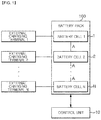
- FIG. 3 is a schematic diagram illustrating the case where three battery cells are provided in the electric vehicle battery charging system using the multi-layer division method according to the embodiment of the present invention.
- the battery pack may be configured by three battery cells (1, 2, and 3) in the electric vehicle battery charging system using the multi-layer division method according to the embodiment of the present invention.
- each of the battery cells (1, 2, and 3) may have the same charging capacity
- the battery cells (1, 2, and 3) may include charging terminals (1-1, 2-1, and 3-1), respectively, and external charging terminals (1-2, 2-2, and 3-2) may be connected to the charging terminals (1-1, 2-1, and 3-1).
- connection portions (A) may be provided between the respective battery cells (1, 2, and 3), and a connection state of the connection portion (A) may be on and off through a switching means included in the connection portion (A). An operation of the switching means may be performed by the control unit (10).
- a specific operation process is as follows. That is, in a case where the external charging terminals (1-2, 2-2, and 3-2) are connected to the charging terminals (1-1, 2-1, and 3-1) of the three battery cells (1, 2, and 3), the battery cells (1, 2, and 3) need to be charged independently, and thus, the control unit (10) turns off the switching means such that connection states of the two connection portions (A) become off states.
- the external charging terminal 1 (1-2) is connected to the charging terminal (1-1) of the battery cell 1 which is one of the three battery cells (1, 2, and 3)
- the external charging device is in a state of being connected to the battery cell 1
- the control unit (10) performs a control such that the connection state of the connection portion (A) is turned on so as to maintain a state in which the other battery cells (2 and 3) are connected to the battery cell 1 (1). That is, this case corresponds to a case where there is only one external charging device or a case where there is no problem that it takes a long time in charging (a situation in which slow charging is requested).
- the battery cell 1 (1) and the battery cell 2 (2) may be charged through separate charging devices, the connection portion (A) connecting the two battery cells may be controlled by the control unit (10) such that the state is off, and the remaining battery cell 3 (3) has to be charged in connection with the charging of the battery cell 2 (2) because the remaining battery cell is not connected to a separate external charging device.
- the connection portion A connecting the battery cell 2 (2) to the battery cell 3 (3) has to be maintained in the on state.
- the battery cells may be charged individually or in a group according to situations of the external charging device or intention of a user which uses the electric vehicle, and the electric vehicle battery may be charged in various ways through the present system.
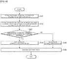
- FIG. 4 is a flowchart illustrating the electric vehicle battery charging method using the multi-layer division method according to another embodiment of the present invention.
- the electric vehicle battery charging method using the multi-layer division method according to another embodiment of the present invention may be implemented by including a first step of forming charging terminal in a plurality of battery cells, respectively, a second step of forming a connection portion through which a current may flow or may not flow between the plurality of battery cells, a third step of controlling on/off states of the connection portion according to whether there is an external charging terminal connected to a charging terminal formed in each of the battery cells, and a fourth step of charging the battery pack according to the on/off state of the connection portion.
- charging terminals are formed in a plurality of battery cells respectively (S41), the connection portion (A) through which a current may flow or may be blocked is formed between the plurality of battery cells (S42), whether or not an external charging terminal is connected to the charging terminal formed in each battery cell is determined (S43), a state of the connection portion (A) is controlled to be off if the external charging terminal is connected (S44), the state of the connection portion (A) is controlled to be on if the external charging terminal is not connected (S45), and after the processes, the battery pack is charged (S46), as illustrated in FIG. 4 .
- steps S43 and S44 in a case where the external charging terminal is connected to the battery cell, the connection state of other battery cells that may be connected to the relevant battery cell becomes an off state (through on/off operations of the connection portion (A)). That is, the battery cell connected to the external charging terminal is separated from the other battery cells. However, if the other battery cells that may be connected to the relevant battery cell is not connected to the external charging terminal, the other battery cells are not charged separately, and thus, in this case, the connection with the relevant battery cell connected to the external charging terminal has to be maintained, and thereby, the connection portion (A) between two battery cells may be turned on.
- steps S43 and S45 in a case where the external charging terminal is not connected to the battery cell, the connection state of other battery cells that may be connected to the battery cell is on (through on/off operations of the connection portion (A)). That is, as described above, in a state where the external charging terminal is not separately connected to the relevant battery cell, the connection state with the other battery cells that may be connected to the relevant battery cell has to be maintained, and the connection portion (A) may be maintained in the on state.
- charging time of a car with a battery of a large capacity is effectively reduced.
- a battery pack of an electric vehicle has a capacity of 100 kW, it takes 2 to 3 hours to charge the battery pack with a fast charger of 50 kW.
- the battery pack may be simultaneously charged through two terminals, and thereby, the total charging time may be reduced by half compared with the battery pack of related art.
- the charging time may be reduced as the number of simultaneous charging terminals (the terminals formed in the respective battery cells and the external charging terminals) increases.
- the battery pack is divided into a plurality of battery cells and each battery cell includes each charging terminal because the recommended battery capacity of an electric vehicle requiring a traveling distance of 500 km in the future will be more than or equal to 100 kW.
- the buffer time more than or equal to 40 hours is usually required.
- charging time of 2 to 3 hours is required even if the battery is charged with the fast charger of 50 kW class, and for this reason, the charging system of the present invention will be more useful.
- the battery pack will have a capacity greater than or equal to 400 kW, and for this reason, charging time will be remarkably reduced by dividing the battery pack into a plurality of battery cells and by simultaneously charging each battery cell (battery compartment).
Landscapes
- Engineering & Computer Science (AREA)
- Power Engineering (AREA)
- Mechanical Engineering (AREA)
- Transportation (AREA)
- Sustainable Energy (AREA)
- Sustainable Development (AREA)
- Life Sciences & Earth Sciences (AREA)
- Manufacturing & Machinery (AREA)
- General Chemical & Material Sciences (AREA)
- Electrochemistry (AREA)
- Chemical Kinetics & Catalysis (AREA)
- Chemical & Material Sciences (AREA)
- Physics & Mathematics (AREA)
- Automation & Control Theory (AREA)
- General Physics & Mathematics (AREA)
- Charge And Discharge Circuits For Batteries Or The Like (AREA)
- Electric Propulsion And Braking For Vehicles (AREA)
Applications Claiming Priority (2)
| Application Number | Priority Date | Filing Date | Title |
|---|---|---|---|
| KR1020160169730A KR101751236B1 (ko) | 2016-12-13 | 2016-12-13 | 다층 분할 방식을 이용한 전기자동차 배터리 충전 시스템 및 방법 |
| PCT/KR2016/014683 WO2018110734A1 (fr) | 2016-12-13 | 2016-12-15 | Système et procédé de charge de batterie de véhicule électrique utilisant un schéma de division multicouche |
Publications (2)
| Publication Number | Publication Date |
|---|---|
| EP3556596A1 true EP3556596A1 (fr) | 2019-10-23 |
| EP3556596A4 EP3556596A4 (fr) | 2020-07-15 |
Family
ID=59514611
Family Applications (1)
| Application Number | Title | Priority Date | Filing Date |
|---|---|---|---|
| EP16924095.9A Withdrawn EP3556596A4 (fr) | 2016-12-13 | 2016-12-15 | Système et procédé de charge de batterie de véhicule électrique utilisant un schéma de division multicouche |
Country Status (5)
| Country | Link |
|---|---|
| US (1) | US20190275908A1 (fr) |
| EP (1) | EP3556596A4 (fr) |
| JP (1) | JP2020501498A (fr) |
| KR (1) | KR101751236B1 (fr) |
| WO (1) | WO2018110734A1 (fr) |
Cited By (1)
| Publication number | Priority date | Publication date | Assignee | Title |
|---|---|---|---|---|
| EP4503251A4 (fr) * | 2022-05-27 | 2025-08-06 | Lg Energy Solution Ltd | Bloc-batterie ayant une fonction de charge rapide améliorée |
Families Citing this family (4)
| Publication number | Priority date | Publication date | Assignee | Title |
|---|---|---|---|---|
| KR102465069B1 (ko) | 2017-11-15 | 2022-11-09 | 삼성전자주식회사 | 배터리 충전 방법 및 장치 |
| DE102018202589A1 (de) * | 2018-02-21 | 2019-08-22 | Audi Ag | Batterie für ein elektrisch angetriebenes Kraftfahrzeug und Ladevorrichtung zum Aufladen einer Batterie eines elektrisch angetriebenen Kraftfahrzeugs |
| KR102106574B1 (ko) * | 2018-07-11 | 2020-05-06 | 성균관대학교산학협력단 | 충전 효율 개선된 전기 자동차용 급속 충전 장치 및 그 충전 방법 |
| CN109927585B (zh) * | 2019-03-21 | 2022-07-01 | 唐国齐 | 电动车携便式自动充电装置 |
Family Cites Families (14)
| Publication number | Priority date | Publication date | Assignee | Title |
|---|---|---|---|---|
| JP3208655B2 (ja) * | 1996-08-13 | 2001-09-17 | 富士通電装株式会社 | 電気自動車用充電装置 |
| KR200189819Y1 (ko) | 1999-10-13 | 2000-07-15 | 엘지전자주식회사 | 셀의 균형 충전이 가능한 배터리 팩 |
| JP2008278635A (ja) | 2007-04-27 | 2008-11-13 | Mitsubishi Motors Corp | 電気自動車用バッテリ充電装置及び方法 |
| TWI350019B (en) * | 2007-09-11 | 2011-10-01 | Yen Chung Jao | Battery structure and power supply device of the battery structure |
| KR20100132583A (ko) * | 2009-06-10 | 2010-12-20 | 주식회사 엘지화학 | 휴대폰용 데이터 케이블을 이용하여 충전할 수 있는 것을 특징으로 하는 노트북용 배터리 팩 |
| JP5552817B2 (ja) | 2010-01-25 | 2014-07-16 | ソニー株式会社 | 電力管理システム、電力管理装置、電力管理方法、蓄電装置、及び電動移動体 |
| KR101184752B1 (ko) | 2010-06-03 | 2012-09-20 | 정윤이 | 배터리 팩 그리고 배터리 팩의 충전 방법 |
| KR101574548B1 (ko) * | 2010-12-13 | 2015-12-07 | 주식회사 엘지화학 | 배터리 팩의 충전 장치 및 방법 |
| US9444118B2 (en) * | 2011-05-26 | 2016-09-13 | Samsung Sdi Co., Ltd. | Battery pack |
| KR101241670B1 (ko) * | 2011-09-05 | 2013-03-11 | 에스케이씨앤씨 주식회사 | 분리 충전할 배터리 셀들을 적응적으로 가변시키는 배터리 충전 장치 및 그의 배터리 충전 제어방법 |
| JP2014146418A (ja) * | 2013-01-25 | 2014-08-14 | Toyota Motor Corp | 組電池の処理装置及び組電池の処理方法 |
| KR101508180B1 (ko) | 2013-10-18 | 2015-11-20 | 주식회사 이지트로닉스 | 마일드 하이브리드 전기자동차용 충전장치 |
| DE102014109430A1 (de) * | 2014-07-07 | 2016-01-07 | Dr. Ing. H.C. F. Porsche Aktiengesellschaft | Energiespeichersystem und Verfahren zum Betrieb eines Energiespeichersystems |
| DE102015004119A1 (de) * | 2015-03-31 | 2016-10-06 | Audi Ag | Kraftfahrzeug mit einem elektrischen Energiespeicher und zwei Ladeschnittstellen, Ladesystem sowie Verfahren |
-
2016
- 2016-12-13 KR KR1020160169730A patent/KR101751236B1/ko not_active Expired - Fee Related
- 2016-12-15 EP EP16924095.9A patent/EP3556596A4/fr not_active Withdrawn
- 2016-12-15 WO PCT/KR2016/014683 patent/WO2018110734A1/fr not_active Ceased
- 2016-12-15 US US16/349,074 patent/US20190275908A1/en not_active Abandoned
- 2016-12-15 JP JP2019531152A patent/JP2020501498A/ja active Pending
Cited By (1)
| Publication number | Priority date | Publication date | Assignee | Title |
|---|---|---|---|---|
| EP4503251A4 (fr) * | 2022-05-27 | 2025-08-06 | Lg Energy Solution Ltd | Bloc-batterie ayant une fonction de charge rapide améliorée |
Also Published As
| Publication number | Publication date |
|---|---|
| JP2020501498A (ja) | 2020-01-16 |
| EP3556596A4 (fr) | 2020-07-15 |
| US20190275908A1 (en) | 2019-09-12 |
| WO2018110734A1 (fr) | 2018-06-21 |
| KR101751236B1 (ko) | 2017-06-27 |
Similar Documents
| Publication | Publication Date | Title |
|---|---|---|
| JP6419992B2 (ja) | ハイブリッドエネルギー貯蔵モジュールシステム | |
| KR101680526B1 (ko) | 배터리 제어 장치 및 방법 | |
| US9783037B2 (en) | Vehicle | |
| US9365114B2 (en) | High voltage system of electric vehicles | |
| US10513200B2 (en) | Vehicle battery system and method of controlling charge of battery in the system | |
| US9799873B2 (en) | Battery assembly of a battery having two different cell types | |
| EP3556596A1 (fr) | Système et procédé de charge de batterie de véhicule électrique utilisant un schéma de division multicouche | |
| EP2670018B1 (fr) | Système de batterie de véhicule électrique | |
| US20180345806A1 (en) | Vehicle battery system and method of controlling same | |
| US20160046201A1 (en) | System and method for controlling battery to extend driving mileage | |
| CN112078417B (zh) | 用于控制对车辆的高压电网结构进行充电的装置和方法 | |
| CN114940075A (zh) | 车载太阳能充电控制系统、车载太阳能充电控制方法以及记录介质 | |
| US9048050B2 (en) | Electric power supply control apparatus for vehicle | |
| EP3188342A1 (fr) | Système de charge intelligent des blocs de batteries de véhicule électrique | |
| KR20190027450A (ko) | 전기 자동차 트랙션 배터리의 두 가지 모드의 직렬/병렬 스위칭 구조 | |
| WO2018153431A1 (fr) | Procédé et agencement d'équilibrage d'un bloc-batterie | |
| CN111746278A (zh) | 电池控制器和电池控制方法 | |
| US11964620B2 (en) | Vehicular power supply device | |
| CN104908604B (zh) | 机载电网 | |
| EP3674129B1 (fr) | Système de commande de charge de véhicule | |
| US20240235214A9 (en) | Equalization control device for battery | |
| JP2020167027A (ja) | 電源装置 | |
| JP6186845B2 (ja) | 補助電池システム | |
| JP2012147617A (ja) | 車両用バッテリ充電装置 | |
| JP6295942B2 (ja) | 充電装置 |
Legal Events
| Date | Code | Title | Description |
|---|---|---|---|
| STAA | Information on the status of an ep patent application or granted ep patent |
Free format text: STATUS: THE INTERNATIONAL PUBLICATION HAS BEEN MADE |
|
| PUAI | Public reference made under article 153(3) epc to a published international application that has entered the european phase |
Free format text: ORIGINAL CODE: 0009012 |
|
| STAA | Information on the status of an ep patent application or granted ep patent |
Free format text: STATUS: REQUEST FOR EXAMINATION WAS MADE |
|
| 17P | Request for examination filed |
Effective date: 20190619 |
|
| AK | Designated contracting states |
Kind code of ref document: A1 Designated state(s): AL AT BE BG CH CY CZ DE DK EE ES FI FR GB GR HR HU IE IS IT LI LT LU LV MC MK MT NL NO PL PT RO RS SE SI SK SM TR |
|
| AX | Request for extension of the european patent |
Extension state: BA ME |
|
| DAV | Request for validation of the european patent (deleted) | ||
| DAX | Request for extension of the european patent (deleted) | ||
| A4 | Supplementary search report drawn up and despatched |
Effective date: 20200615 |
|
| RIC1 | Information provided on ipc code assigned before grant |
Ipc: H02J 7/00 20060101ALI20200608BHEP Ipc: H01M 10/44 20060101AFI20200608BHEP Ipc: B60L 58/10 20190101ALI20200608BHEP Ipc: G05B 19/042 20060101ALI20200608BHEP Ipc: B60L 58/19 20190101ALI20200608BHEP Ipc: B60L 58/21 20190101ALI20200608BHEP Ipc: H01M 10/04 20060101ALI20200608BHEP Ipc: B60L 53/53 20190101ALI20200608BHEP Ipc: H01M 10/46 20060101ALI20200608BHEP Ipc: B60L 53/16 20190101ALI20200608BHEP Ipc: B60L 53/14 20190101ALI20200608BHEP Ipc: H02J 7/14 20060101ALI20200608BHEP |
|
| STAA | Information on the status of an ep patent application or granted ep patent |
Free format text: STATUS: THE APPLICATION IS DEEMED TO BE WITHDRAWN |
|
| 18D | Application deemed to be withdrawn |
Effective date: 20210113 |