EP3556536A1 - Thermoformungsmaschine und -verfahren - Google Patents
Thermoformungsmaschine und -verfahren Download PDFInfo
- Publication number
- EP3556536A1 EP3556536A1 EP18168490.3A EP18168490A EP3556536A1 EP 3556536 A1 EP3556536 A1 EP 3556536A1 EP 18168490 A EP18168490 A EP 18168490A EP 3556536 A1 EP3556536 A1 EP 3556536A1
- Authority
- EP
- European Patent Office
- Prior art keywords
- mold
- cavities
- thermoforming
- sheet
- machine according
- Prior art date
- Legal status (The legal status is an assumption and is not a legal conclusion. Google has not performed a legal analysis and makes no representation as to the accuracy of the status listed.)
- Withdrawn
Links
Images

Classifications
-
- B—PERFORMING OPERATIONS; TRANSPORTING
- B29—WORKING OF PLASTICS; WORKING OF SUBSTANCES IN A PLASTIC STATE IN GENERAL
- B29C—SHAPING OR JOINING OF PLASTICS; SHAPING OF MATERIAL IN A PLASTIC STATE, NOT OTHERWISE PROVIDED FOR; AFTER-TREATMENT OF THE SHAPED PRODUCTS, e.g. REPAIRING
- B29C51/00—Shaping by thermoforming, i.e. shaping sheets or sheet like preforms after heating, e.g. shaping sheets in matched moulds or by deep-drawing; Apparatus therefor
- B29C51/26—Component parts, details or accessories; Auxiliary operations
- B29C51/30—Moulds
-
- B—PERFORMING OPERATIONS; TRANSPORTING
- B29—WORKING OF PLASTICS; WORKING OF SUBSTANCES IN A PLASTIC STATE IN GENERAL
- B29C—SHAPING OR JOINING OF PLASTICS; SHAPING OF MATERIAL IN A PLASTIC STATE, NOT OTHERWISE PROVIDED FOR; AFTER-TREATMENT OF THE SHAPED PRODUCTS, e.g. REPAIRING
- B29C2791/00—Shaping characteristics in general
- B29C2791/004—Shaping under special conditions
- B29C2791/007—Using fluid under pressure
-
- B—PERFORMING OPERATIONS; TRANSPORTING
- B29—WORKING OF PLASTICS; WORKING OF SUBSTANCES IN A PLASTIC STATE IN GENERAL
- B29C—SHAPING OR JOINING OF PLASTICS; SHAPING OF MATERIAL IN A PLASTIC STATE, NOT OTHERWISE PROVIDED FOR; AFTER-TREATMENT OF THE SHAPED PRODUCTS, e.g. REPAIRING
- B29C2793/00—Shaping techniques involving a cutting or machining operation
- B29C2793/0009—Cutting out
-
- B—PERFORMING OPERATIONS; TRANSPORTING
- B29—WORKING OF PLASTICS; WORKING OF SUBSTANCES IN A PLASTIC STATE IN GENERAL
- B29C—SHAPING OR JOINING OF PLASTICS; SHAPING OF MATERIAL IN A PLASTIC STATE, NOT OTHERWISE PROVIDED FOR; AFTER-TREATMENT OF THE SHAPED PRODUCTS, e.g. REPAIRING
- B29C2793/00—Shaping techniques involving a cutting or machining operation
- B29C2793/009—Shaping techniques involving a cutting or machining operation after shaping
-
- B—PERFORMING OPERATIONS; TRANSPORTING
- B29—WORKING OF PLASTICS; WORKING OF SUBSTANCES IN A PLASTIC STATE IN GENERAL
- B29C—SHAPING OR JOINING OF PLASTICS; SHAPING OF MATERIAL IN A PLASTIC STATE, NOT OTHERWISE PROVIDED FOR; AFTER-TREATMENT OF THE SHAPED PRODUCTS, e.g. REPAIRING
- B29C51/00—Shaping by thermoforming, i.e. shaping sheets or sheet like preforms after heating, e.g. shaping sheets in matched moulds or by deep-drawing; Apparatus therefor
- B29C51/10—Forming by pressure difference, e.g. vacuum
-
- B—PERFORMING OPERATIONS; TRANSPORTING
- B29—WORKING OF PLASTICS; WORKING OF SUBSTANCES IN A PLASTIC STATE IN GENERAL
- B29L—INDEXING SCHEME ASSOCIATED WITH SUBCLASS B29C, RELATING TO PARTICULAR ARTICLES
- B29L2031/00—Other particular articles
- B29L2031/712—Containers; Packaging elements or accessories, Packages
- B29L2031/7132—Bowls, Cups, Glasses
-
- B—PERFORMING OPERATIONS; TRANSPORTING
- B29—WORKING OF PLASTICS; WORKING OF SUBSTANCES IN A PLASTIC STATE IN GENERAL
- B29L—INDEXING SCHEME ASSOCIATED WITH SUBCLASS B29C, RELATING TO PARTICULAR ARTICLES
- B29L2031/00—Other particular articles
- B29L2031/74—Domestic articles
- B29L2031/7404—Dishes
Definitions
- the present invention relates to a thermoforming machine and a thermoforming process, in particular for the production of plastic articles.
- Thermoforming is a known process for hot-molding plastics, used to produce a large number of plastic articles such as plates, cups, trays, tubs, etc.
- thermoformable material is conveyed into a mold having a certain number of cavities which reproduce the form of the desired articles.
- the cavities in general follow a square array.
- the mold is typically formed by two half-molds, typically a bottom half-mold and a top half-mold, operated by a press.
- the cavities may be arranged to form an array such that a working cycle of the press produces a batch of articles (multiple forming).
- the sheet may adhere to the cavities under a suction effect (vacuum thermoforming) or under the action of a pressure exerted by a fluid, typically air (pressure thermoforming).
- one of the two half-molds contains the cavities and a suitable vacuum system; the other half-mold therefore has a relatively simple design.
- Vacuum thermoforming in fact may apply to the sheet a (negative) pressure whose theoretical maximum value is limited to atmospheric pressure; for some materials this force is not able to ensure the desired adhesion to the cavities and pressure thermoforming is required to apply a greater pressure to the sheet.
- polypropylene is a material which generally requires pressure thermoforming.
- thermoforming After thermoforming it is known to separate the thermoformed articles from the sheet by means of a punching or cutting operation using a suitable punch/die system.
- punching denotes a process which cuts out the contour of articles without however completely separating the articles from the waste sheet, i.e. leaving some parts of the original sheet (called “indicators”) connecting together the articles, such that they may be transported collectively together with the sheet.
- cutting denotes a process which separates completely the articles, such that each of the articles, after the cutting step, constitutes a separate object.
- thermoforming machine extends essentially in a longitudinal direction from a material loading side, for example where a reel of the thermoformable sheet is arranged or where an extruder for the said sheet is present, to a side of collecting and expelling the thermoformed articles.
- the transportation system of the sheet therefore is arranged to convey the sheet in a forward feeding direction and, in the thermoforming mold, it is possible to define an inlet side, where the sheet of material enters between the two half-molds, and an opposite outlet side of output of the articles.
- a punching or cutting station Downstream of the thermoforming mold a punching or cutting station may be provided.
- thermoforming In some embodiments it is known to perform both thermoforming and cutting inside the same mold.
- This technique of combined forming and cutting in a single mold is advantageous because it allows performing two machining steps in a single station of the machine and, in particular, because it avoids the need to remove the articles from the forming mold and the repositioning of the articles with appropriate centering in a cutting mold.
- said technique is not always feasible, mainly because the parts are thermoformed and cut in a single mold and therefore a removal or expulsion member is required to withdraw the single articles from the mold, which may not be easy to implement.
- thermoforming and cutting mold withdrawing the articles from the thermoforming and cutting mold is relatively easy in vacuum thermoforming process, because one of the two half-molds has an open structure which allows a removal member to pass through.
- both half-molds are sealed and closed and do not allow the withdrawal; in order to expel the parts it is necessary, for example, to open the mold and incline or turn over the bottom half-mold, which requires a tilting movement of the half-mold during each molding cycle, something which slows down the production cycle; moreover it involves putting a large mass into alternating movement, with the associated problems, in particular in machines with a high capacity which must perform several cycles per minute.
- thermoforming mold it is desirable to convey the sheet from the thermoforming mold to the cutting mold using the same transportation system which feeds the thermoforming mold.
- the sheet remains constantly engaged with the transportation system, without leaving it, during the steps of introduction into the thermoforming mold, thermoforming and transportation towards the cutting mold.
- the sheet inevitably cools during the transfer between the two molds; the consequent shrinkage of the material deforms the semi-finished product, modifies the relative position of the articles already thermoformed and makes more difficult centering the articles in the cutting mold. Lack of a precise centering during the cutting step may result in a non-conformity of the shape of the product or unacceptable quality defects, such as sharp edges.
- shrinkage indicates, as is known, the deformations induced by cooling of the plastic material. More generally, in addition to affecting centering during the cutting step, a shrinkage of the semi-finished product after thermoforming may produce defects in the finished product, for example may deform the articles.
- thermoforming mold may cause tensions and deformations due to shrinkage.
- the material is generally heated to a high temperature, in order to allow plastic deformation, in a heater located immediately upstream of the mold. Therefore the inlet side of the mold is a "hot” side, while the opposite outlet side of the mold is a "cold” side.
- the amount of the shrinkage depends on the material.
- polypropylene (PP) is subject to a shrinkage of approximately 18-20 parts per thousand, which is a relatively high value: it corresponds to about 2 mm per meter; if it is considered that the cutting step must have a very high precision (usually of the order of micrometers), it can be understood that shrinkage poses a major problem.
- the amount of shrinkage also depends on the specific weight of the material (and therefore the mass of the single articles) which is very variable depending on the applications.
- the specific weight of a multilayer material of this type may vary significantly according to the number and the composition of the layers and the degree of shrinkage may vary consequently.
- the shrinkage is not only significant, but also variable depending on the product made and the thermoformable material used.
- the machines of the prior art do not yet offer a solution to this problem which is also flexible and adaptable to different features of the materials. It should be considered that there is a growing interest in high-performance multilayer materials specific for the intended use of the articles and, consequently, there is a need to provide thermoforming machines able to adapt to different materials.
- the object of the invention is to overcome the limitations and drawbacks of the prior art mentioned further above.
- the main object of the present invention is to counteract the effects of shrinkage of the material during a thermoforming process. More particularly, an object of the invention is to solve the problem of centering of thermoformed articles for a cutting step in connection with machines and processes which perform thermoforming and cutting in two separate stages. Even more particularly, an object of the invention is to provide a thermoforming machine which is able to maintain correct centering during cutting also when using different materials which have different shrinkage values.
- thermoforming machine comprising:
- Said adjustable-position molds are termed hereinbelow movable cavities.
- the mold is provided with at least some movable cavities; preferably all the cavities of the mold are movable.
- said movable cavities are displaceable (adjustable) along at least a first adjustment axis.
- Said first adjustment axis is preferably perpendicular to said feeding direction.
- said movable cavities are displaceable along two axes, preferably two perpendicular axes.
- said movable cavities are displaceable along said first adjustment axis perpendicular to the feeding direction and along a second adjustment axis which is perpendicular to the first adjustment axis.
- the movable cavities have a predefined adjustment travel along said first axis and, where provided, along said second axis.
- the adjustment travel may be the same along two axes or, in other embodiments, the adjustment travel permitted along the first axis may be different (greater or smaller) than the adjustment travel allowed along the second axis.
- Said movable cavities can be locked in a desired position within the respective adjustment travel.
- the cavities may be arranged in an array.
- the displacement of the movable cavities allows modifying the configuration of said array.
- the cavities are arranged in a converging layout in the feeding direction which will be described below.
- said thermoforming mold comprises a first half-mold and a second half-mold, and one of said half-molds supports said movable cavities.
- the thermoforming mold comprises a bottom half-mold and a top half-mold. More preferably the movable cavities are inserted in the bottom half-mold.
- each of the movable cavities is associated with a respective holder and said holder is displaceable relative to the supporting half-mold.
- the holders are secured to the supporting half-molds by an adjustment system which defines an adjustment travel for the position of the holders on one axis or more preferably on two axes.
- the cavities are separated by recesses on the surface of the supporting half-mold, said recesses being preferably arranged to form a square grid. More preferably, said recesses are arranged between said form holders.
- the machine comprises a cutting station downstream of said thermoforming mold.
- the transportation system is configured to transport the sheet of thermoformable material, after the thermoforming step, from the thermoforming mold to the cutting station, while keeping a constant driving engagement with said sheet ("continuous" transportation). The sheet therefore passes from the forming step to the cutting step without leaving the engagement with the transportation system.
- the driving engagement between sheet and transportation system is for example mechanical.
- the transportation system comprises two motor-driven chains provided with teeth which engage the edges of the sheet and allow driving the sheet along the length of the machine.
- the array of cavities assumes an arrangement such that a pitch between the cavities, perpendicular to said feeding direction, decreases along said forward feeding direction, from an input side to an output side of the thermoforming mold.
- thermoforming cavities converge in the forward feeding direction of the sheet of material, i.e. in the direction from the inlet side towards the outlet side of the thermoforming mold.
- Said arrangement may be termed a trapezium arrangement.
- a closed line which connects the centers of the cavities which form the contour of the array defines a trapezium or essentially trapezium-like shape.
- said arrangement of converging cavities is able to compensate for the shrinkage deformation effect.
- said converging arrangement effectively offsets the shrinkage effect and, in particular, allows maintaining the desired centering of the articles during the transfer to a downstream cutting station.
- the movable cavities may be positioned by the operator before starting the production, depending on the characteristics of the material and/or of the article and the expected amount of shrinkage.
- the operator may arrange the movable cavities in the aforementioned trapezium-like configuration by adjusting the pitch between the cavities depending on the expected amount of shrinkage, which depends essentially on the type of material and thermoforming process conditions of the article.
- the fine adjustment of the position of the movable cavities, if necessary, may be determined by a person skilled in the art also by means of test runs.
- the separation recesses between the holders create tracks on the sheet which provide the sheet with a certain elasticity and better adaptation to the cutting process, as will be explained more clearly below, with the aid of an example.
- the invention allows to adapt the machine to the characteristics of the material and to compensate for the effects of the shrinkage.
- the invention is particularly advantageous for machines with a continuous transportation between thermoforming and cutting, since it avoids or in any case reduces the loss of centering caused by the shrinkage of the material.
- the invention is particularly advantageous for the thermoforming of articles made of polypropylene or made of a polypropylene multilayer.
- An aspect the invention also relates to a thermoforming process according to the attached claims.
- an aspect of the invention relates to a process for thermoforming articles comprising:
- the process comprises a cutting step which separates the thermoformed articles from said sheet, wherein said cutting step is performed in a cutting mold downstream of said thermoforming mold, and the sheet is conveyed from the thermoforming mold to the cutting mold while keeping a constant driving engagement with a transportation system.
- the process involves: arranging each of the movable cavities in a desired position within a respective adjustment travel; locking the movable cavities in the desired position; performing one or more thermoforming cycles.
- Said adjustment travel may be along one axis or along two axes.
- said process comprises arranging the cavities of the mold in a configuration such that a spacing pitch between the cavities, perpendicular to a feeding direction of the thermoformable sheet relative to the mold, decreases in a forward feeding direction of the sheet.
- the process provides that the cavities are arranged in parallel rows, perpendicular to the feeding direction, each row having a respective pitch between the cavities, and the pitch between the rows decreasing in said forward feeding direction, the cavities thus converging in the forward feeding direction.
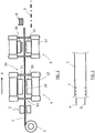
- thermoforming machine in a thermoforming machine, a sheet of thermoformable material 1 is conveyed from a reel 2 into a heating unit 3, which heats the material to a temperature sufficient for thermoforming. After heating, the sheet 1 is introduced into a thermoforming mold 4; downstream of said thermoforming mold 4 the sheet is conveyed into a cutting mold 5.
- Fig. 1 shows by way of example a reel 2, but the sheet 1 may be fed in a different way, for example by a film extruder.
- thermoformable material 1 is transported by a suitable transportation system, in an oriented feeding direction A, which also defines a forward feeding direction.
- a suitable transportation system in an oriented feeding direction A, which also defines a forward feeding direction.
- said forward feeding direction is left to right.
- the transportation system of the sheet 1 is configured to keep a constant engagement with the sheet 1 along the machine, and in particular without interruption, from the thermoforming mold 4 to the cutting mold 5. Consequently the sheet does not abandon the transportation system during the transfer between said two molds.
- FIG. 2 An example of a transportation system is schematically shown in Fig. 2 , wherein two chains 6 are provided with teeth 7 to engage the edges of the sheet 1.
- the sheet 1 for example is a multilayer sheet (or film).
- thermoforming step in the mold 4 generates, by means of plastic deformation of the sheet 1, a series of articles such as trays or small plates.
- the cutting mold 5 separates said articles from the sheet 1. Downstream of the cutting mold 5 a batch of thermoformed articles 8 and waste material 9 are therefore collected.
- the articles 8 are extracted from the cutting mold 5 by means of a suitable member known per se.
- the thermoforming mold 4 comprises essentially a bottom half-mold 10 and a top half-mold 11. Said half-molds are operated by a press 12. The figure shows the mold 4 open; the press 12 allows to close the two half-molds onto the sheet 1, thus performing the thermoforming process of said sheet.
- An inlet side 13 and an output side 14 of the mold 4 can be defined.
- the inlet inlet side 13 constitutes a hot side since the sheet comes directly from the heating unit 3; the outlet side 14, directed towards the cutting mold 5, may be termed cold side.
- the cutting mold 5 is structurally similar to the mold 4 and comprises a punch assembly 15 and a die 16 with an actuating press 17. Said mold 5 can be conventional and therefore is not further described.
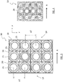
- thermoforming mold 4 comprises a plurality of cavities which are distributed on the upper face 18 of the bottom half-mold 10.
- Fig. 3 shows the half-mold 10 viewed from above and in a preferred embodiment.
- Said half-mold 10 has a frame 19 which carries a plurality of holders 20. Each of said holders 20 contains a cavity 21 intended to form one of the articles 8.
- the holders 20 have an adjustable position, i.e. are movable, relative to the frame 19. Each holder 20 is preferably movable, with a given adjustment travel, along two adjustment axes denoted by x and y in Fig. 3 .
- a first adjustment axis x is perpendicular to the feeding direction A
- a second adjustment axis y is parallel to said direction A.
- the holders 20 may be arranged, advantageously, in a converging setup as shown in Fig. 3 , wherein the spacing pitch between the centers of the cavities 21 decreases in the forward feeding direction A.
- the figure shows that the pitch p1 between two cavities adjacent to the inlet side 13 of the mold (hot side) is greater than a spacing p2 between two cavities adjacent to the output side 14 (cold side).
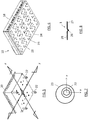
- the cavities are therefore arranged to converge in the forward feeding direction A, as can be noted in Fig. 3 , where the cavities converge and approach each other from left to right. It can be also noted that the cavities so arranged form substantially a trapezium. Connecting the centers of the cavities gives a closed line 29 defining a trapezium, as shown in Fig. 4 .
- a suitable adjustment system is provided. Said adjustment system allows displacing the movable cavities and locking the cavities in the desired position.
- FIGs. 5 to 7 show a preferred embodiment of said adjustment system.
- a movable holder 20 is provided with a plurality of supporting elements, for example four screws 22, which are received in seats 23 in the bottom 24 of the half-mold 10.
- Said seats 23 receive the screws 22 with a certain play which gives the adjustment travel along one or two axes.
- the seats 23 are formed by holes having a diameter greater than that of the screws 22; in other embodiments, for example, the seats 23 may have the form of eyelets with a shape other than circular, for example an elongated shape.
- the screws 22 grip the bottom side of the form holder 20 against the half-mold 10. By loosening the screws 22 the holder may be displaced, within the adjustment travel allowed by the size of the holes 23. By tightening the screws 22 the operator can lock the holder 20 in the desired position.
- Fig. 9 shows a holder 20 in the locked position. Said figure shows that, by tightening the screws 22, the form holder 20 is locked in a desired position, within the permitted adjustment travel.
- the operator may arrange the holders and modify the pitch of the cavities, preferably with the trapezium configuration described above, taking into account the type of material and therefore the shrinkage which will be encountered during transfer from the thermoforming mold 4 to the cutting mold 5.
- the transportation system remains continuously engaged with the sheet 1 between the two molds 4 and 5, i.e. for example the teeth 7 of the chains 6 remain engaged with the sheet 1.
- the suitable arrangement of the movable cavities compensates for the shrinkage of material and helps keep the articles centered in the cutting mold 5.
- FIG. 8 Another feature of the invention is given by a number of recesses between the holders 20 (shown in Fig. 3 ).
- the effect of said recesses 25 is shown in Fig. 8 : the recesses 25 form tracks 26 in the sheet 1 (as a result of the plastic material which penetrates into the recesses 25) and each of said tracks behaves substantially in the manner of a resilient bellows, allowing for example the portions 27 and 28 to slightly move away from or towards each other.
- This feature provides a further self-centering capacity of the thermoformed articles on the sheet 1 during the cutting step.
- a mold as shown in Fig. 3 , comprises twelve cavities for making articles with a circular shape (plates) having a diameter of 215 mm.
- the material is a polypropylene sheet with a width of 1045 mm and a thickness of 0.4 mm; thermoforming is performed at a temperature of about 145 °C (inlet temperature of the sheet into the mold).
- Each cavity is inserted in a holder and the holders are arranged in a 3x4 array.
- the holders form three parallel rows perpendicular to the feeding direction of the sheet.
- Each holder is secured to the half-mold by means of four screws inserted into holes or eyelets which allow an adjustment travel of 3.5 mm along the two axes.
- the holders are arranged in a trapezium, wherein the pitch of the row on the mold inlet side is 244.1 mm, the spacing of the central row is 243.5 mm and the spacing of the row on the output side is 242.9 mm.
Landscapes
- Engineering & Computer Science (AREA)
- Mechanical Engineering (AREA)
- Blow-Moulding Or Thermoforming Of Plastics Or The Like (AREA)
- Moulds For Moulding Plastics Or The Like (AREA)
Priority Applications (1)
| Application Number | Priority Date | Filing Date | Title |
|---|---|---|---|
| EP18168490.3A EP3556536A1 (de) | 2018-04-20 | 2018-04-20 | Thermoformungsmaschine und -verfahren |
Applications Claiming Priority (1)
| Application Number | Priority Date | Filing Date | Title |
|---|---|---|---|
| EP18168490.3A EP3556536A1 (de) | 2018-04-20 | 2018-04-20 | Thermoformungsmaschine und -verfahren |
Publications (1)
| Publication Number | Publication Date |
|---|---|
| EP3556536A1 true EP3556536A1 (de) | 2019-10-23 |
Family
ID=62620615
Family Applications (1)
| Application Number | Title | Priority Date | Filing Date |
|---|---|---|---|
| EP18168490.3A Withdrawn EP3556536A1 (de) | 2018-04-20 | 2018-04-20 | Thermoformungsmaschine und -verfahren |
Country Status (1)
| Country | Link |
|---|---|
| EP (1) | EP3556536A1 (de) |
Cited By (5)
| Publication number | Priority date | Publication date | Assignee | Title |
|---|---|---|---|---|
| CN114030199A (zh) * | 2021-11-09 | 2022-02-11 | 海允实业(上海)有限公司 | 用于塑料产品加工的生产线 |
| CN114654705A (zh) * | 2022-02-18 | 2022-06-24 | 成都领益科技有限公司 | 热压成型工艺、热压装置、扬声器网罩及耳机 |
| US20230051517A1 (en) * | 2021-08-11 | 2023-02-16 | Fabri-Kal Corporation | Trim tool with adjustable trim centers |
| CN116080048A (zh) * | 2023-03-13 | 2023-05-09 | 青岛铭毅智能科技有限公司 | 一种自动吸塑包装机及其使用方法 |
| EP4647238A1 (de) | 2024-05-06 | 2025-11-12 | WM Thermoforming Machines SA | Thermoformmaschine |
Citations (4)
| Publication number | Priority date | Publication date | Assignee | Title |
|---|---|---|---|---|
| US5385465A (en) * | 1990-12-28 | 1995-01-31 | Greiwe; Daniel | Verticle thermoforming apparatus |
| WO2001017753A1 (en) * | 1999-09-08 | 2001-03-15 | Weasy Pack International Ltd. | Releasing undercut moulded containers after a thermoforming process |
| WO2007088161A2 (en) * | 2006-02-02 | 2007-08-09 | Inovapak Srl | Apparatuses and methods for thermoforming containers from plastic foils |
| DE202016005408U1 (de) * | 2016-09-06 | 2017-10-09 | Multivac Sepp Haggenmüller Se & Co. Kg | Tiefziehverpackungsmaschine |
-
2018
- 2018-04-20 EP EP18168490.3A patent/EP3556536A1/de not_active Withdrawn
Patent Citations (4)
| Publication number | Priority date | Publication date | Assignee | Title |
|---|---|---|---|---|
| US5385465A (en) * | 1990-12-28 | 1995-01-31 | Greiwe; Daniel | Verticle thermoforming apparatus |
| WO2001017753A1 (en) * | 1999-09-08 | 2001-03-15 | Weasy Pack International Ltd. | Releasing undercut moulded containers after a thermoforming process |
| WO2007088161A2 (en) * | 2006-02-02 | 2007-08-09 | Inovapak Srl | Apparatuses and methods for thermoforming containers from plastic foils |
| DE202016005408U1 (de) * | 2016-09-06 | 2017-10-09 | Multivac Sepp Haggenmüller Se & Co. Kg | Tiefziehverpackungsmaschine |
Cited By (8)
| Publication number | Priority date | Publication date | Assignee | Title |
|---|---|---|---|---|
| US20230051517A1 (en) * | 2021-08-11 | 2023-02-16 | Fabri-Kal Corporation | Trim tool with adjustable trim centers |
| US12427689B2 (en) * | 2021-08-11 | 2025-09-30 | Fabri-Kal Llc | Trim tool with adjustable trim centers |
| CN114030199A (zh) * | 2021-11-09 | 2022-02-11 | 海允实业(上海)有限公司 | 用于塑料产品加工的生产线 |
| CN114030199B (zh) * | 2021-11-09 | 2023-08-22 | 海允实业(上海)有限公司 | 用于塑料产品加工的生产线 |
| CN114654705A (zh) * | 2022-02-18 | 2022-06-24 | 成都领益科技有限公司 | 热压成型工艺、热压装置、扬声器网罩及耳机 |
| CN114654705B (zh) * | 2022-02-18 | 2023-09-15 | 成都领益科技有限公司 | 热压成型工艺、扬声器网罩及耳机 |
| CN116080048A (zh) * | 2023-03-13 | 2023-05-09 | 青岛铭毅智能科技有限公司 | 一种自动吸塑包装机及其使用方法 |
| EP4647238A1 (de) | 2024-05-06 | 2025-11-12 | WM Thermoforming Machines SA | Thermoformmaschine |
Similar Documents
| Publication | Publication Date | Title |
|---|---|---|
| EP3556536A1 (de) | Thermoformungsmaschine und -verfahren | |
| US6719551B2 (en) | Thermoplastic molding process and apparatus | |
| US4477243A (en) | Thermoforming apparatus | |
| US4636348A (en) | System for thermoforming articles such as picnic plates in a pair of simultaneously fed, continuous thermoplastic webs which subsequently move into nested relation, and then dually trimming the nested articles from the webs | |
| JPH11506063A (ja) | プリカットダイ装置及び熱成形方法及び装置 | |
| US6394783B1 (en) | Continuous rotary melt thermoformer | |
| JP7463401B2 (ja) | 包装の包装本体を製造するための方法および装置 | |
| EP3946891B1 (de) | Mehrkavitätenform für eine thermoformmaschine zur verwendung in einem thermoformverfahren von dünnwandigen kunststoffprodukten in hohen mengen | |
| WO2020012721A1 (ja) | プレス成形物の連続成形方法及びプレス成形物の連続成形装置 | |
| US3964856A (en) | Vacuum moulding techniques | |
| EP0322697A1 (de) | Maschine zur Herstellung warmgeformter Gegenstände | |
| US9694533B2 (en) | Method and device for manufacturing containers by thermoforming | |
| US3548043A (en) | Method for vacuum forming hollow articles from two sheets of thermoplastic material | |
| CN222203935U (zh) | 一种隐形眼镜模具用的单排分料装置 | |
| US4830596A (en) | Vacuum thermoforming rotary machine | |
| US20100126901A1 (en) | Thermofrom a tray insitu with an article | |
| EP0970792B1 (de) | Verfahren und Vorrichtung zum Formen eines mit einer Folie beschichteten Schaumkunststoffes, insbesondere für einen Polsterkörper eines Kraftfahrzeuges | |
| EP0019005B1 (de) | Verfahren und Vorrichtung zum Herstellen von Verpackungsbehältern für Suppositorien | |
| US4952264A (en) | Method for producing plastic components | |
| JP7300773B1 (ja) | 熱成形装置 | |
| TWI749478B (zh) | 修整裝置 | |
| US20070063388A1 (en) | Method and device for transferring thermoformed articles | |
| JPS6245813B2 (de) | ||
| IT201800006051A1 (it) | Sistema per processare e movimentare un materiale plastico per la formatura di oggetti cavi. | |
| JPH1058536A (ja) | 熱可塑性樹脂シートの熱成形装置 |
Legal Events
| Date | Code | Title | Description |
|---|---|---|---|
| PUAI | Public reference made under article 153(3) epc to a published international application that has entered the european phase |
Free format text: ORIGINAL CODE: 0009012 |
|
| STAA | Information on the status of an ep patent application or granted ep patent |
Free format text: STATUS: THE APPLICATION HAS BEEN PUBLISHED |
|
| AK | Designated contracting states |
Kind code of ref document: A1 Designated state(s): AL AT BE BG CH CY CZ DE DK EE ES FI FR GB GR HR HU IE IS IT LI LT LU LV MC MK MT NL NO PL PT RO RS SE SI SK SM TR |
|
| AX | Request for extension of the european patent |
Extension state: BA ME |
|
| STAA | Information on the status of an ep patent application or granted ep patent |
Free format text: STATUS: REQUEST FOR EXAMINATION WAS MADE |
|
| 17P | Request for examination filed |
Effective date: 20200410 |
|
| RBV | Designated contracting states (corrected) |
Designated state(s): AL AT BE BG CH CY CZ DE DK EE ES FI FR GB GR HR HU IE IS IT LI LT LU LV MC MK MT NL NO PL PT RO RS SE SI SK SM TR |
|
| STAA | Information on the status of an ep patent application or granted ep patent |
Free format text: STATUS: EXAMINATION IS IN PROGRESS |
|
| 17Q | First examination report despatched |
Effective date: 20201201 |
|
| STAA | Information on the status of an ep patent application or granted ep patent |
Free format text: STATUS: THE APPLICATION IS DEEMED TO BE WITHDRAWN |
|
| 18D | Application deemed to be withdrawn |
Effective date: 20210413 |