EP3556496B1 - Outil de forage - Google Patents
Outil de forage Download PDFInfo
- Publication number
- EP3556496B1 EP3556496B1 EP18167758.4A EP18167758A EP3556496B1 EP 3556496 B1 EP3556496 B1 EP 3556496B1 EP 18167758 A EP18167758 A EP 18167758A EP 3556496 B1 EP3556496 B1 EP 3556496B1
- Authority
- EP
- European Patent Office
- Prior art keywords
- flute portion
- drilling tool
- flute
- tool
- tool body
- Prior art date
- Legal status (The legal status is an assumption and is not a legal conclusion. Google has not performed a legal analysis and makes no representation as to the accuracy of the status listed.)
- Active
Links
Images


Classifications
-
- B—PERFORMING OPERATIONS; TRANSPORTING
- B23—MACHINE TOOLS; METAL-WORKING NOT OTHERWISE PROVIDED FOR
- B23B—TURNING; BORING
- B23B51/00—Tools for drilling machines
-
- B—PERFORMING OPERATIONS; TRANSPORTING
- B23—MACHINE TOOLS; METAL-WORKING NOT OTHERWISE PROVIDED FOR
- B23B—TURNING; BORING
- B23B51/00—Tools for drilling machines
- B23B51/0006—Drills with cutting inserts
- B23B51/0011—Drills with cutting inserts with radially inner and outer cutting inserts
-
- B—PERFORMING OPERATIONS; TRANSPORTING
- B23—MACHINE TOOLS; METAL-WORKING NOT OTHERWISE PROVIDED FOR
- B23B—TURNING; BORING
- B23B51/00—Tools for drilling machines
- B23B51/06—Drills with lubricating or cooling equipment
-
- B—PERFORMING OPERATIONS; TRANSPORTING
- B23—MACHINE TOOLS; METAL-WORKING NOT OTHERWISE PROVIDED FOR
- B23B—TURNING; BORING
- B23B2251/00—Details of tools for drilling machines
- B23B2251/40—Flutes, i.e. chip conveying grooves
- B23B2251/4011—Two flutes merge into one flute
-
- B—PERFORMING OPERATIONS; TRANSPORTING
- B23—MACHINE TOOLS; METAL-WORKING NOT OTHERWISE PROVIDED FOR
- B23B—TURNING; BORING
- B23B2251/00—Details of tools for drilling machines
- B23B2251/40—Flutes, i.e. chip conveying grooves
- B23B2251/406—Flutes, i.e. chip conveying grooves of special form not otherwise provided for
Definitions
- the present invention belongs to the technical field of metal cutting. More specifically the present invention belongs to the field of drilling tools used for metal cutting in machines such as computer numerical control, i.e. CNC, machines.
- the present invention is related to a drilling tool according to the preamble of claim 1.
- a drilling tool is known from EP 1 419 839 A1 .
- the drilling tool according to the present invention is particularly designed for chip forming machining of metallic work pieces and for drilling composite materials.
- Such a drilling tool comprises a tool body having a center axis defining a longitudinal direction of the drilling tool, the tool body having an axially forward end and an axially rearward end, the distance in the longitudinal direction between the forward end and the rearward end defining a length of the drilling tool, and at least two indexable cutting inserts, which are arranged at the axially forward end, a first indexable cutting insert being arranged at a radially inner position and a second indexable cutting insert being arranged at a radially outer position, the tool body comprising a first flute portion extending axially rearward from the first indexable cutting insert, and a second flute portion extending axially rearward from the second indexable cutting insert.
- the cutting speed is rather low due to its location at a small radius while the cutting speed is much higher for a cutting insert at a radially outer position, i.e. located at a larger radius.
- the different cutting parameters which are strongly varying from the radially inner cutting insert to the radially outer cutting insert cause the formation of different types and sizes of chips, which have different chip transportation requirements.
- the forces acting on the chips lead to a repeated deformation of chips, which in turn results in the generation of additional heat and unbalanced and varying cutting forces.
- This in turn causes an unstable behavior of the drilling tool during a cutting operation and may even cause breaking of the drilling tool, in particular of small diameter drilling tools which are less stable and may not withstand unbalanced and varying cutting forces.
- Even for drilling tools having a larger diameter the unbalanced and varying cutting forces may result in vibrations and may cause an increase of wear.
- a main object of the present invention is to provide a drilling tool having increased stability and torsional rigidity in order to obviate or at least minimize some or all of the afore-mentioned problems.
- a further object is to provide a drilling tool having improved chip transport characteristics.
- a still further object is to provide a drilling tool which can be manufactured in an economical way.
- the first flute portion of the drilling tool according to claim 1 transitions into the second flute portion at an axially forward transition area of the tool body, thereby forming only one flute of the drilling tool.
- the chip transport of the drilling tool is improved.
- the larger chips produced by the radially outer cutting insert promote transportation of the smaller chips produced by the radially inner cutting insert in an advantageous way.
- said transition area By having said transition area at an axially forward location, the positive effect on the smaller chips is achieved close to the formation of these smaller chips.
- the transition area is located at an axial distance from the forward end amounting to no more than L/3.
- the transition area is located at an axial distance from the forward end amounting to no more than L/10.
- the first flute portion runs internally through the tool body forming a through hole from a front end surface to the second flute portion.
- the chips generated by the first, i.e. the radial inner, cutting insert are transported internally through the tool body to the second flute portion.
- these chips do not come in contact with the hole wall being generated during this transport and the surface finish of the hole wall is improved.
- the first flute portion opens into a front end surface of the tool body via a first opening.
- the second flute portion opens into a peripheral surface of the tool body, which improves chip transport as well as enables production of the drilling tool in an economical manner.
- the second flute portion is open to the peripheral surface along the entire extent thereof in the longitudinal direction. This further improves chip transport and further simplifies production of the drilling tool.
- the first opening intersects a first plane being perpendicular to the center axis, thereby defining a first area, which is no more than 80% of the area of the front end surface.
- the first opening intersects a first plane being perpendicular to the center axis, thereby defining a first area, which is no more than 60% of the area of the front end surface.
- a cross-section of the first flute portion in a second plane perpendicular to the center axis is smaller than a cross-section of the second flute portion in a third plane perpendicular to the center axis.
- the second flute portion is helical.
- first flute portion as well as the second flute portion are helical. Thereby, a smooth transition between the first and second flute portions is established. At the same time, chip transport is improved.
- the pitch of the first flute portion is substantially the same as the pitch of the second flute portion, which further improves chip transport. Also, this enables production of the drilling tool in an economical way.
- the tool body is a single-piece body made from one piece of material. Firstly, this enables production of the drilling tool in an economical way, since there is no need for connecting a plurality of different tool body parts. Secondly, a more rigid tool body is provided, without any connections between different tool body parts. Such connections are typically more prone to breakage at heavy loads.
- said second flute portion has a radial depth, which is larger than a radius of the tool body along at least a first longitudinal segment of the second flute portion. In this way a larger second flute portion is provided, which enables transport of larger quantities of chips and decreases problems with chip congestion.
- the tool body comprises a coolant channel, which opens into the front end surface of the tool body via a coolant channel opening, which is adjacent to the first indexable cutting insert.
- coolant may be provided close to first indexable cutting insert, thereby improving performance of the drilling tool.
- the second flute portion has a partly circular cross-section, a first intersection of the second flute portion and the peripheral surface and a second intersection of the second flute portion and the peripheral surface together forming an angle of no more than 80°.
- the second flute portion is somewhat closed, i.e. in cross-section the second flute portion is larger or wider towards the center of the drilling tool, than at its intersection with the peripheral surface. In this way, the chips are better contained within the flute portion during chip transport, thereby improving surface quality of the hole wall being generated by the drilling tool. Also, a more rigid drilling tool is obtained in this way.
- a cross-section of the first flute portion gradually increases from the front end surface to the second flute portion. In this way a more rigid drilling tool towards the front end surface is obtained.
- a drilling tool is a device which is adapted for use in metal or composite cutting operations, primarily drilling operations, but the drilling tool can also be used for helical interpolation, boring, plunging and turning operations.
- the drilling tool is arranged to be mounted or connected to a machine tool (not shown), such as a CNC machine, either directly or indirectly by one or more tool holders, to a tool spindle of the machine tool.
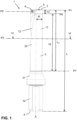
- the drilling tool 1 comprises a tool body 2, which has a center axis A defining a longitudinal direction of the drilling tool 1.
- the drilling tool 1 is rotatable around the center axis A in a rotational direction 23, see Fig 3 .
- the tool body 2 has an axially forward end 3 and an axially rearward end 4. The distance in the longitudinal direction between the forward end 3 and the rearward end 4 defines a total length L of the drilling tool 1.
- a peripheral surface 17 extends on a front cylindrical portion 30 of the tool body. Said front cylindrical portion, i.e.
- the mounting portion 32 has a generally cylindrical form.
- the front cylindrical portion 30 extends between a first plane P1, which is perpendicular to the center axis A, and a seventh plane P7, which is parallel with the plane P1, but is located axially behind or lower than the first plane P1, as illustrated in Fig 1 .
- the seventh plane P7 indicates the transition between the front cylindrical portion 30 and the collar portion 31.
- the axial distance between the first plane P1 and the seventh plane P7 defines a maximum cutting length Lc of the drilling tool, i.e. how deep a hole can be machined with the drilling tool without interfering with the collar portion 31.
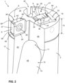
- the drilling tool further comprises at least two indexable cutting inserts 5, 6, which are arranged at the axially forward end .
- a first indexable cutting insert 5 is arranged at a radially inner position 7 and a second indexable cutting insert 6 is arranged at a radially outer position 8.
- the tool body 2 comprises a radially inner pocket 24 for receiving the first indexable cutting insert 5 and a radially outer pocket 25 for receiving the second indexable cutting insert 6.
- the cutting inserts 5, 6 are secured in their respective pockets 24, 25 by means of a suitable clamping arrangement, such as by a screw 26.
- the tool body 2 of the drilling tool is a single-piece body made from one piece of material, preferably tool steel, whereas the cutting inserts 5, 6 preferably are made of a hard metal such as cemented carbide.
- the indexable cutting inserts 5,6 include a front insert end surface 35, 35', a back insert end surface 36, 36' and an insert side surface 37,37'.
- the cutting inserts 5,6 further include at least one cutting edge 38, 38' defined by the intersection of a front insert end surface 35, 35' and an insert side surface 37, 37'.
- the exact shape and cutting geometry of the first indexable cutting insert 5 and the second indexable cutting insert 6 may vary based on user requirements.
- the cutting inserts 5, 6 as illustrated have a generally rectangular or square configuration, but also other shapes, such as triangular inserts, are conceivable.
- the cutting inserts 5,6 have an insert side surface 37,37' defining four sides, which meet in four corner surface portions 39, 39'.
- corner surface portions 39, 39' are curved.
- said cutting edge 38, 38' includes a straight cutting edge portion 40, 40', formed by the intersection of the front insert end surface 35, 35' and the insert side surface 37, 37'.
- said cutting edge 38, 38' includes one or more radiused or curved cutting edge portions 41, 41' formed by the intersection of the front insert end surface 35, 35' and the corner surface portions 39, 39' of the insert side surface 37, 37'.
- the cutting inserts 5, 6 are indexable, i.e. rotatable around the axis defined by the screw 26, into four different active positions. Also other configurations, such as cutting inserts having two or three different active positions are conceivable.
- first indexable cutting insert 5 and the second indexable cutting insert 6 may be of identical or different configuration.
- first, radially inner, indexable cutting insert 5 is different from the second, radially outer, indexable cutting insert 6. This is best illustrated in Fig. 2-3 , where each of the four sides of the radially inner cutting insert 5 includes more surface portions, than corresponding four sides of the radially outer cutting insert 6. Accordingly, the cutting edge 38 of the radially inner cutting insert 5 includes more cutting edge portions, of different configuration, than the cutting edge 38' of the radially outer cutting insert 6.
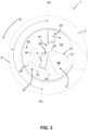
- the first, radially inner, indexable cutting insert 5 and the second, radially outer, indexable cutting insert 6 have radially overlapping working or active portions of their respective cutting edges 38, 38'.
- the radially overlapping working or active portions of the cutting edges 38, 38' together machine the full diameter 2R of the drilling tool.
- the first radially inner cutting insert 5 and the second radially outer cutting insert 6 are not mounted exactly 180° in relation to each other. Rather, in top view of the drilling tool, a fourth plane P4 being tangent to the front insert end surface 35 of the radially inner cutting insert 5 and parallel with the center axis A, and a fifth plane P5 being tangent to the front insert end surface 35' of the radially outer cutting insert 6 and parallel with the center axis A, together form an angle ⁇ amounting to 177°.
- the first radially inner cutting insert 5 and the second radially outer cutting insert 6 are slightly rotationally offset, i.e. offset in the rotational direction 23.
- the tool body 2 comprises a first flute portion 9 extending axially rearward from the first indexable cutting insert 5, and a second flute portion 10 extending axially rearward from the second indexable cutting insert 6.
- the first flute portion 9 transitions into the second flute portion 10 at an axially forward transition area 11 of the tool body 2, thereby forming only one flute 12 of the drilling tool 1.
- the transition area 11 is located at an axial distance 13 from the forward end 3 amounting to no more than L/3.
- the transition area 11 is located at an axial distance 13 from the forward end 3, which is smaller than L/10.
- the axial distance 13 is the distance between a first plane P1, which is perpendicular to the center axis A, and a sixth plane P6, which is parallel with said first plane P1, but located axially behind or lower than the first plane P1.
- the first flute portion 9 runs internally through the tool body 2 forming a through hole from a front end surface 14 of the tool body to the second flute portion 10.
- the peripheral surface 17 is continuous and not interrupted by the first flute portion 9.
- the first flute portion 9 opens into the front end surface 14 of the tool body 2 via a first opening 15.
- the first opening 15 has a generally round shape.
- the first opening 15 includes a large arc 27, roughly having the form of a half-circle, which is connected to two smaller arcs 28, 29, which each is connected to the radially inner insert pocket 24.
- the generally round shape of the first opening 15 is formed by said three arcs 27, 28, 29 together with the radially inner insert pocket 24.
- the area covered by said first opening 15 is smaller than the area of the front end surface 14.
- the front end surface 14 is perpendicular to the center axis A in a first plane P1.
- the first opening 15 intersects the first plane P1, which is perpendicular to the center axis A, thereby defining a first area 16.
- the first opening 15 intersects the front end surface 14, thereby defining the area 16 being delimited by the radially inner insert pocket 24 and the three arcs 27, 28, 29.
- the first area 16 is no more than 80% of the area of the front end surface 14. In the embodiment of Fig. 1-6 , the first area 16 is no more than 60% of the area of the front end surface 14.
- the second flute portion 10 opens into the peripheral surface 17 of the tool body 2.
- the second flute portion 10 is open to the peripheral surface 17 along the entire extent thereof in the longitudinal direction.
- the second flute portion 10 is open to the peripheral surface 17 along the front cylindrical portion 30 of the tool body.
- the second flute portion 10 continues from the front cylindrical portion 30 into the collar portion 31 and ends in the conical envelope surface of the collar portion 31.
- the first flute portion 9 has a generally smaller cross-section than the cross-section of second flute portion 10. More specifically, the cross-section of the first flute portion 9 in a second plane P2 perpendicular to the center axis A is smaller than a cross-section of the second flute portion 10 in a third plane P3 perpendicular to the center axis A.
- the first plane P1 is tangent with the forward end 3 of the drilling tool, and is also tangent with the front end surface 14.
- the plane P2 is parallel with the plane P1, but is located axially behind or lower than the plane P1, as illustrated in Fig 1 .
- the plane P3 is parallel with the planes P1 and P2, but is located axially behind or lower than the plane P2, which is also apparent from Fig. 1 .
- the first flute portion 9 may have varying or substantially constant cross-section along the axial extent of the first flute portion 9.
- the size of the first flute portion 9 may vary or be substantially constant along the axial extent thereof.
- the first flute portion 9 has a substantially constant cross-section.
- the cross-section of the first flute portion 9 increases gradually from the front end surface 14 to the second flute portion 10.
- the first flute portion 9 becomes gradually larger or has a generally conical configuration along its extent in the longitudinal direction from the front end surface 14 to the second flute portion 10.
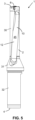
- the first flute portion 9 as well as the second flute portion 10 are helical.
- the first flute portion 9 and the second flute portion 10 run in a helical manner in the longitudinal direction of the drilling tool.
- the pitch of the first flute portion 9 is substantially the same as the pitch of the second flute portion 10, so as to form one continuous, helical flute 12 having one and the same pitch.
- the second flute portion 10 comprises a curved inner surface 45.
- the tool body 2 comprises a first flat surface 43 extending from the front end surface 14 and the radially outer insert pocket 25 to the curved inner surface 45.
- the first flat surface 43 intersects the peripheral surface 17 and is substantially parallel with the plane P5, i.e. substantially parallel with the front insert end surface 35' of the radially outer cutting insert 6.
- the tool body 2 further comprises a second flat surface 44 extending from the front end surface 14 to the curved inner surface 45.
- the second flat surface 44 intersects the peripheral surface 17 and is oriented in parallel with the center axis A and substantially at right angle with the first flat surface 43.
- the first flute portion comprises a curved inner surface 46, which adjoins the arc 27 at the front end surface 14.
- the second flute portion 10 has a radial depth RD, which is larger than a radius R of the tool body 2.
- a radial distance RD from an intersection between the second flute portion 10 and the peripheral surface 17 is larger than a radius of the tool body 2, i.e. the radial distance from the peripheral surface 17 to the center axis A.
- a first intersection 21 is formed between the second flute portion 10, more specifically, the curved surface 45 thereof, and the peripheral surface 17.
- a first radial distance RD 1 larger than the the radius R is formed between the first intersection 21 and the curved surface 45 of the second flute portion.
- a second intersection 22 is formed between the second flute portion 10, more specifically, the curved surface 45 thereof, and the peripheral surface 17.
- a second radial distance RD 2 larger than the the radius R is formed between the second intersection 22 and the curved surface 45 of the second flute portion 10.
- the first radial distance RD 1 may be equal to or different from the second radial distance RD 2 .
- the second flute portion 10 has a radial depth RD, which is larger than a radius R of the tool body 2, along at least a first longitudinal segment 18 of the second flute portion 10. In the embodiment illustrated in Fig. 1-6 , the first longitudinal segment 18 extends the between the sixth plane P6 and the seventh plane P7.
- the first longitudinal segment 18 extends between the transition area 11, i.e. where the first flute portion 9 transitions into the second flute portion 10, and the transition between the front cylindrical portion 30 and the collar portion 31.
- the first longitdunal segment 18 extends a major part of the maximum cutting length Lc of the drilling tool.
- the first longitdunal segment 18 is shorter, for example such that it extends from the sixth plane P6 but ends before, or above, the seventh plane P7.
- the tool body 2 comprises a coolant channel 19, which opens into the front end surface 14 of the tool body 2 via a coolant channel opening 20, which is adjacent to the first indexable cutting insert 5.
- the coolant channel opening is located close to the first indexable cutting insert 5, but more distant in relation to the second indexable cutting insert 6.
- the coolant channel opening 20 is substantially circular.
- the tool body 2 further comprises a first groove 33, which is arranged in the front end surface 14 and connects the coolant channel with the first flute portion 9.
- the tool body 2 comprises a second groove 34, which is arranged in the front end surface 14 and connects the coolant channel with the second flute portion 10.
- the tool body comprises an elongate recess 42, extending from the front end surface 14 in the longitudinal direction of the drilling tool and extending from the peripheral surface 17 to the first flute portion 9 in the radial direction.
- This recess 42 enables the insertion of a fastening tool, such as a screwdriver, from outside the drilling tool through this recess 42 into the first flute portion 9 reaching the screw 26 for fastening the radially inner cutting insert 5 in the radially inner insert pocket 24.
- the second flute portion 10 has a partly circular cross-section, i.e. a cross section of the curved surface 45 of the helical flute 12 will generate a curve being at least partly circular.
- the first intersection 21 of the second flute portion 10 and the peripheral surface 17 and the second intersection 22 of the second flute portion 10 and the peripheral surface 17 together form an angle ⁇ of no more than 80°.
- the first radial distance RD, and the second radial distance RD 2 together enclose the angle ⁇ being no more than 80°.
- the second flute portion 10 is somewhat closed.
- the second flute portion 10 is larger or wider towards the center axis A of the drilling tool, than at its intersection with the peripheral surface.
- the dimensions of the drilling tool as described above can be configured based on user requirements.
- the total cutting length Lc of the drilling tool 1 may be 30 mm or larger, but normally not larger than 540 mm.
- diameters 2R of the drilling tool include diameters from 10 mm to 60 mm.
- the relationship between drilling tool diameter 2R and maximum cutting length Lc is preferably configured such that Lc/2R is at least 3 but not more than 9.
- the flute of the drilling tool may be partly or completely coated with materials improving either the wear resistance and/or the chip transport.
- the second flute portion may be helical, whereas the first flute portion has a more straight configuration.
Landscapes
- Engineering & Computer Science (AREA)
- Mechanical Engineering (AREA)
- Drilling Tools (AREA)
Claims (14)
- Outil de forage (1) comprenant :un corps d'outil (2) comportant un axe central (A) qui définit une direction longitudinale de l'outil de forage (1) ;le corps d'outil comportant une extrémité axialement avant (3) et une extrémité axialement arrière (4), la distance dans la direction longitudinale entre l'extrémité axialement avant (3) et l'extrémité axialement arrière (4) définissant une longueur (L) de l'outil de forage (1) ; etau moins deux inserts de coupe pouvant être indexés (5, 6), lesquels inserts sont agencés au niveau de l'extrémité axialement avant (3), un premier insert de coupe pouvant être indexé (5) étant agencé au niveau d'une position radialement interne (7) et un second insert de coupe pouvant être indexé (6) étant agencé au niveau d'une position radialement externe (8) ;le corps d'outil (2) comprenant :une première partie de cannelure (9) qui est étendue axialement vers l'arrière depuis le premier insert de coupe pouvant être indexé (5) ; etune seconde partie de cannelure (10) qui est étendue axialement vers l'arrière depuis le second insert de coupe pouvant être indexé (6) ;dans lequel :la première partie de cannelure (9) réalise une transition selon et à l'intérieur de la seconde partie de cannelure (10) au niveau d'une zone de transition axialement avant (11) du corps d'outil (2), d'où ainsi la formation de seulement une cannelure (12) de l'outil de forage (1) ;la zone de transition axialement avant (11) est localisée à une distance axiale (13) de l'extrémité axialement avant (3) qui est égale à pas plus de L/3 ; etla seconde partie de cannelure (10) est ouverte et débouche sur une surface périphérique (17) le long de son étendue complète dans la direction longitudinale ; etcaractérisé en ce que :
la seconde partie de cannelure (10) présente une profondeur radiale (RD) qui est plus grande qu'un rayon (R) du corps d'outil (2) le long d'au moins un premier segment longitudinal (18) de la seconde partie de cannelure (10). - Outil de forage (1) selon la revendication 1, caractérisé en ce que la zone de transition axialement avant (11) est localisée à une distance axiale (13) de l'extrémité axialement avant (3) qui est égale à pas plus de L/10.
- Outil de forage (1) selon l'une quelconque des revendications précédentes, caractérisé en ce que la première partie de cannelure (9) est étendue de façon interne au travers du corps d'outil (2) en formant un trou traversant depuis une surface d'extrémité avant (14) jusqu'à la seconde partie de cannelure (10).
- Outil de forage (1) selon l'une quelconque des revendications précédentes, caractérisé en ce que la première partie de cannelure (9) est ouverte et débouche à l'intérieur d'une surface d'extrémité avant (14) du corps d'outil (2) via une première ouverture (15).
- Outil de forage (1) selon la revendication 4, caractérisé en ce que la première ouverture (15) intersecte un premier plan (P1) qui est perpendiculaire à l'axe central (A), d'où ainsi la définition d'une première zone (16) dont l'aire est égale à pas plus de 80 % de l'aire de la surface d'extrémité avant (14).
- Outil de forage (1) selon la revendication 5, caractérisé en ce que la première ouverture (15) intersecte un premier plan (P1) qui est perpendiculaire à l'axe central (A), d'où ainsi la définition d'une première zone (16) dont l'aire est égale à pas plus de 60 % de l'aire de la surface d'extrémité avant (14).
- Outil de forage (1) selon l'une quelconque des revendications précédentes, caractérisé en ce qu'une section en coupe transversale de la première partie de cannelure (9) dans un deuxième plan (P2) qui est perpendiculaire à l'axe central (A) est plus petite qu'une section en coupe transversale de la seconde partie de cannelure (10) dans un troisième plan (P3) qui est perpendiculaire à l'axe central (A).
- Outil de forage (1) selon l'une quelconque des revendications précédentes, caractérisé en ce que la seconde partie de cannelure (10) est en hélice.
- Outil de forage (1) selon l'une quelconque des revendications précédentes, caractérisé en ce que la première partie de cannelure (9) de même que la seconde partie de cannelure (10) sont en hélice.
- Outil de forage (1) selon la revendication 9, caractérisé en ce que le pas de la première partie de cannelure (9) est sensiblement le même que le pas de la seconde partie de cannelure (10).
- Outil de forage (1) selon l'une quelconque des revendications précédentes, caractérisé en ce que le corps d'outil (2) est un corps en une seule pièce réalisé à partir d'une pièce de matériau unique.
- Outil de forage (1) selon l'une quelconque des revendications précédentes, caractérisé en ce que le corps d'outil (2) comprend un canal d'agent de refroidissement (19), lequel canal est ouvert et débouche à l'intérieur de la surface d'extrémité avant (14) du corps d'outil (2) via une ouverture de canal d'agent de refroidissement (20), laquelle ouverture de canal est adjacente au premier insert de coupe pouvant être indexé (5).
- Outil de forage (1) selon l'une quelconque des revendications précédentes, caractérisé en ce que la seconde partie de cannelure (10) présente une section en coupe transversale partiellement circulaire, une première intersection (21) de la seconde partie de cannelure et de la surface périphérique (17) et une seconde intersection (22) de la seconde partie de cannelure et de la surface périphérique (17) formant en association un angle (β) de pas plus de 80°.
- Outil de forage (1) selon la revendication 3, caractérisé en ce qu'une section en coupe transversale de la première partie de cannelure (9) augmente de façon progressive depuis la surface d'extrémité avant (14) jusqu'à la seconde partie de cannelure (10).
Priority Applications (3)
| Application Number | Priority Date | Filing Date | Title |
|---|---|---|---|
| EP18167758.4A EP3556496B1 (fr) | 2018-04-17 | 2018-04-17 | Outil de forage |
| PCT/EP2019/056932 WO2019201538A1 (fr) | 2018-04-17 | 2019-03-20 | Outil de forage |
| US17/047,583 US11548078B2 (en) | 2018-04-17 | 2019-03-20 | Drilling tool |
Applications Claiming Priority (1)
| Application Number | Priority Date | Filing Date | Title |
|---|---|---|---|
| EP18167758.4A EP3556496B1 (fr) | 2018-04-17 | 2018-04-17 | Outil de forage |
Publications (2)
| Publication Number | Publication Date |
|---|---|
| EP3556496A1 EP3556496A1 (fr) | 2019-10-23 |
| EP3556496B1 true EP3556496B1 (fr) | 2024-10-09 |
Family
ID=62017238
Family Applications (1)
| Application Number | Title | Priority Date | Filing Date |
|---|---|---|---|
| EP18167758.4A Active EP3556496B1 (fr) | 2018-04-17 | 2018-04-17 | Outil de forage |
Country Status (3)
| Country | Link |
|---|---|
| US (1) | US11548078B2 (fr) |
| EP (1) | EP3556496B1 (fr) |
| WO (1) | WO2019201538A1 (fr) |
Families Citing this family (1)
| Publication number | Priority date | Publication date | Assignee | Title |
|---|---|---|---|---|
| CN115846730A (zh) * | 2022-12-08 | 2023-03-28 | 株洲钻石切削刀具股份有限公司 | 一种排屑能力强的高效钻孔刀具 |
Citations (1)
| Publication number | Priority date | Publication date | Assignee | Title |
|---|---|---|---|---|
| US5782587A (en) * | 1995-06-23 | 1998-07-21 | August Beck Gmbh & Co. | Drilling tool |
Family Cites Families (12)
| Publication number | Priority date | Publication date | Assignee | Title |
|---|---|---|---|---|
| US1104989A (en) * | 1914-01-15 | 1914-07-28 | Pratt & Whitney Co | Drill. |
| US2912887A (en) * | 1958-03-17 | 1959-11-17 | Rudolf W Andreasson | Single-double spiral drill |
| US3045513A (en) * | 1960-07-05 | 1962-07-24 | Rudolf W Andreasson | Drill |
| US3040605A (en) * | 1960-08-01 | 1962-06-26 | Rudolf W Andreasson | Drill |
| US3824026A (en) * | 1973-03-19 | 1974-07-16 | T Gaskins | Cutting lead tips for drill bits |
| SE411310B (sv) * | 1976-11-17 | 1979-12-17 | Sandvik Ab | Borr, foretredesvis med vendsker |
| US4536107A (en) * | 1983-08-29 | 1985-08-20 | Ex-Cell-O Corporation | Drill bit |
| US5174691A (en) * | 1989-09-05 | 1992-12-29 | Ford Motor Company | High feed rate deep penetration drill |
| SE504339C2 (sv) * | 1994-06-13 | 1997-01-13 | Sandvik Ab | Borrverktyg |
| US7004691B2 (en) * | 2002-11-15 | 2006-02-28 | Unitac Incorporated | Deep hole cutter |
| JP5359066B2 (ja) * | 2008-07-01 | 2013-12-04 | 株式会社タンガロイ | 穴あけ工具 |
| DE102010021212B4 (de) * | 2010-05-21 | 2015-08-13 | Audi Ag | Bohrwerkzeug |
-
2018
- 2018-04-17 EP EP18167758.4A patent/EP3556496B1/fr active Active
-
2019
- 2019-03-20 WO PCT/EP2019/056932 patent/WO2019201538A1/fr not_active Ceased
- 2019-03-20 US US17/047,583 patent/US11548078B2/en active Active
Patent Citations (1)
| Publication number | Priority date | Publication date | Assignee | Title |
|---|---|---|---|---|
| US5782587A (en) * | 1995-06-23 | 1998-07-21 | August Beck Gmbh & Co. | Drilling tool |
Also Published As
| Publication number | Publication date |
|---|---|
| US11548078B2 (en) | 2023-01-10 |
| WO2019201538A1 (fr) | 2019-10-24 |
| EP3556496A1 (fr) | 2019-10-23 |
| US20210114119A1 (en) | 2021-04-22 |
Similar Documents
| Publication | Publication Date | Title |
|---|---|---|
| EP1908543B1 (fr) | Fraise à crayon et procédé de découpe | |
| US5855458A (en) | Rotary cutter | |
| US7909545B2 (en) | Ballnose end mill | |
| EP2181787B1 (fr) | Fraise en bout | |
| JP2013252610A (ja) | ドリル工具用ビット | |
| US20150093207A1 (en) | Deep hole drill tool | |
| EP1930107A2 (fr) | Perceuse | |
| JP2018534159A (ja) | 旋削インサートおよび方法 | |
| US5664914A (en) | Drill | |
| JP6892503B2 (ja) | 回転工具 | |
| EP1679143B1 (fr) | Foret | |
| US7320566B2 (en) | Cutting tool including detachable cutter head | |
| JP5287426B2 (ja) | 切削工具 | |
| US10821526B2 (en) | Rotary tool and method for manufacturing machined product | |
| WO2021230176A1 (fr) | Foret et procédé de fabrication de pièce découpée | |
| EP3556496B1 (fr) | Outil de forage | |
| JP6977228B1 (ja) | 回転切削工具用切削インサートおよび回転切削工具 | |
| JP5286928B2 (ja) | エンドミル | |
| JP7052176B1 (ja) | 切削工具 | |
| RU2771284C2 (ru) | Сверлильная вставка | |
| US20250214155A1 (en) | Drill and method of manufacturing machined product | |
| JP7488349B2 (ja) | 切削インサート、回転工具及び切削加工物の製造方法 | |
| WO2019220778A9 (fr) | Plaquette de coupe pour foret, et foret | |
| JPWO2019189415A1 (ja) | ドリル及び切削加工物の製造方法 | |
| JP7706561B2 (ja) | 回転工具、及び切削加工物の製造方法 |
Legal Events
| Date | Code | Title | Description |
|---|---|---|---|
| PUAI | Public reference made under article 153(3) epc to a published international application that has entered the european phase |
Free format text: ORIGINAL CODE: 0009012 |
|
| STAA | Information on the status of an ep patent application or granted ep patent |
Free format text: STATUS: THE APPLICATION HAS BEEN PUBLISHED |
|
| AK | Designated contracting states |
Kind code of ref document: A1 Designated state(s): AL AT BE BG CH CY CZ DE DK EE ES FI FR GB GR HR HU IE IS IT LI LT LU LV MC MK MT NL NO PL PT RO RS SE SI SK SM TR |
|
| AX | Request for extension of the european patent |
Extension state: BA ME |
|
| STAA | Information on the status of an ep patent application or granted ep patent |
Free format text: STATUS: REQUEST FOR EXAMINATION WAS MADE |
|
| 17P | Request for examination filed |
Effective date: 20200423 |
|
| RBV | Designated contracting states (corrected) |
Designated state(s): AL AT BE BG CH CY CZ DE DK EE ES FI FR GB GR HR HU IE IS IT LI LT LU LV MC MK MT NL NO PL PT RO RS SE SI SK SM TR |
|
| STAA | Information on the status of an ep patent application or granted ep patent |
Free format text: STATUS: EXAMINATION IS IN PROGRESS |
|
| 17Q | First examination report despatched |
Effective date: 20220718 |
|
| REG | Reference to a national code |
Ref legal event code: R079 Ref country code: DE Ref legal event code: R079 Ref document number: 602018075117 Country of ref document: DE Free format text: PREVIOUS MAIN CLASS: B23B0051040000 Ipc: B23B0051000000 |
|
| GRAP | Despatch of communication of intention to grant a patent |
Free format text: ORIGINAL CODE: EPIDOSNIGR1 |
|
| STAA | Information on the status of an ep patent application or granted ep patent |
Free format text: STATUS: GRANT OF PATENT IS INTENDED |
|
| RIC1 | Information provided on ipc code assigned before grant |
Ipc: B23B 51/00 20060101AFI20240417BHEP |
|
| INTG | Intention to grant announced |
Effective date: 20240507 |
|
| GRAS | Grant fee paid |
Free format text: ORIGINAL CODE: EPIDOSNIGR3 |
|
| GRAA | (expected) grant |
Free format text: ORIGINAL CODE: 0009210 |
|
| STAA | Information on the status of an ep patent application or granted ep patent |
Free format text: STATUS: THE PATENT HAS BEEN GRANTED |
|
| P01 | Opt-out of the competence of the unified patent court (upc) registered |
Free format text: CASE NUMBER: APP_45773/2024 Effective date: 20240807 |
|
| AK | Designated contracting states |
Kind code of ref document: B1 Designated state(s): AL AT BE BG CH CY CZ DE DK EE ES FI FR GB GR HR HU IE IS IT LI LT LU LV MC MK MT NL NO PL PT RO RS SE SI SK SM TR |
|
| REG | Reference to a national code |
Ref country code: CH Ref legal event code: EP |
|
| REG | Reference to a national code |
Ref country code: DE Ref legal event code: R096 Ref document number: 602018075117 Country of ref document: DE |
|
| REG | Reference to a national code |
Ref country code: IE Ref legal event code: FG4D |
|
| REG | Reference to a national code |
Ref country code: LT Ref legal event code: MG9D |
|
| REG | Reference to a national code |
Ref country code: NL Ref legal event code: MP Effective date: 20241009 |
|
| REG | Reference to a national code |
Ref country code: AT Ref legal event code: MK05 Ref document number: 1730043 Country of ref document: AT Kind code of ref document: T Effective date: 20241009 |
|
| PG25 | Lapsed in a contracting state [announced via postgrant information from national office to epo] |
Ref country code: NL Free format text: LAPSE BECAUSE OF FAILURE TO SUBMIT A TRANSLATION OF THE DESCRIPTION OR TO PAY THE FEE WITHIN THE PRESCRIBED TIME-LIMIT Effective date: 20241009 |
|
| PG25 | Lapsed in a contracting state [announced via postgrant information from national office to epo] |
Ref country code: NL Free format text: LAPSE BECAUSE OF FAILURE TO SUBMIT A TRANSLATION OF THE DESCRIPTION OR TO PAY THE FEE WITHIN THE PRESCRIBED TIME-LIMIT Effective date: 20241009 |
|
| PG25 | Lapsed in a contracting state [announced via postgrant information from national office to epo] |
Ref country code: PT Free format text: LAPSE BECAUSE OF FAILURE TO SUBMIT A TRANSLATION OF THE DESCRIPTION OR TO PAY THE FEE WITHIN THE PRESCRIBED TIME-LIMIT Effective date: 20250210 Ref country code: HR Free format text: LAPSE BECAUSE OF FAILURE TO SUBMIT A TRANSLATION OF THE DESCRIPTION OR TO PAY THE FEE WITHIN THE PRESCRIBED TIME-LIMIT Effective date: 20241009 Ref country code: IS Free format text: LAPSE BECAUSE OF FAILURE TO SUBMIT A TRANSLATION OF THE DESCRIPTION OR TO PAY THE FEE WITHIN THE PRESCRIBED TIME-LIMIT Effective date: 20250209 |
|
| PG25 | Lapsed in a contracting state [announced via postgrant information from national office to epo] |
Ref country code: FI Free format text: LAPSE BECAUSE OF FAILURE TO SUBMIT A TRANSLATION OF THE DESCRIPTION OR TO PAY THE FEE WITHIN THE PRESCRIBED TIME-LIMIT Effective date: 20241009 |
|
| PG25 | Lapsed in a contracting state [announced via postgrant information from national office to epo] |
Ref country code: BG Free format text: LAPSE BECAUSE OF FAILURE TO SUBMIT A TRANSLATION OF THE DESCRIPTION OR TO PAY THE FEE WITHIN THE PRESCRIBED TIME-LIMIT Effective date: 20241009 |
|
| PG25 | Lapsed in a contracting state [announced via postgrant information from national office to epo] |
Ref country code: ES Free format text: LAPSE BECAUSE OF FAILURE TO SUBMIT A TRANSLATION OF THE DESCRIPTION OR TO PAY THE FEE WITHIN THE PRESCRIBED TIME-LIMIT Effective date: 20241009 |
|
| PG25 | Lapsed in a contracting state [announced via postgrant information from national office to epo] |
Ref country code: NO Free format text: LAPSE BECAUSE OF FAILURE TO SUBMIT A TRANSLATION OF THE DESCRIPTION OR TO PAY THE FEE WITHIN THE PRESCRIBED TIME-LIMIT Effective date: 20250109 |
|
| PG25 | Lapsed in a contracting state [announced via postgrant information from national office to epo] |
Ref country code: LV Free format text: LAPSE BECAUSE OF FAILURE TO SUBMIT A TRANSLATION OF THE DESCRIPTION OR TO PAY THE FEE WITHIN THE PRESCRIBED TIME-LIMIT Effective date: 20241009 Ref country code: GR Free format text: LAPSE BECAUSE OF FAILURE TO SUBMIT A TRANSLATION OF THE DESCRIPTION OR TO PAY THE FEE WITHIN THE PRESCRIBED TIME-LIMIT Effective date: 20250110 Ref country code: AT Free format text: LAPSE BECAUSE OF FAILURE TO SUBMIT A TRANSLATION OF THE DESCRIPTION OR TO PAY THE FEE WITHIN THE PRESCRIBED TIME-LIMIT Effective date: 20241009 |
|
| PG25 | Lapsed in a contracting state [announced via postgrant information from national office to epo] |
Ref country code: PL Free format text: LAPSE BECAUSE OF FAILURE TO SUBMIT A TRANSLATION OF THE DESCRIPTION OR TO PAY THE FEE WITHIN THE PRESCRIBED TIME-LIMIT Effective date: 20241009 |
|
| PGFP | Annual fee paid to national office [announced via postgrant information from national office to epo] |
Ref country code: FR Payment date: 20250321 Year of fee payment: 8 |
|
| PGFP | Annual fee paid to national office [announced via postgrant information from national office to epo] |
Ref country code: IT Payment date: 20250320 Year of fee payment: 8 Ref country code: GB Payment date: 20250306 Year of fee payment: 8 |
|
| PG25 | Lapsed in a contracting state [announced via postgrant information from national office to epo] |
Ref country code: RS Free format text: LAPSE BECAUSE OF FAILURE TO SUBMIT A TRANSLATION OF THE DESCRIPTION OR TO PAY THE FEE WITHIN THE PRESCRIBED TIME-LIMIT Effective date: 20250109 |
|
| PG25 | Lapsed in a contracting state [announced via postgrant information from national office to epo] |
Ref country code: SM Free format text: LAPSE BECAUSE OF FAILURE TO SUBMIT A TRANSLATION OF THE DESCRIPTION OR TO PAY THE FEE WITHIN THE PRESCRIBED TIME-LIMIT Effective date: 20241009 |
|
| PGFP | Annual fee paid to national office [announced via postgrant information from national office to epo] |
Ref country code: DE Payment date: 20250305 Year of fee payment: 8 |
|
| PG25 | Lapsed in a contracting state [announced via postgrant information from national office to epo] |
Ref country code: DK Free format text: LAPSE BECAUSE OF FAILURE TO SUBMIT A TRANSLATION OF THE DESCRIPTION OR TO PAY THE FEE WITHIN THE PRESCRIBED TIME-LIMIT Effective date: 20241009 |
|
| REG | Reference to a national code |
Ref country code: DE Ref legal event code: R097 Ref document number: 602018075117 Country of ref document: DE |
|
| PG25 | Lapsed in a contracting state [announced via postgrant information from national office to epo] |
Ref country code: EE Free format text: LAPSE BECAUSE OF FAILURE TO SUBMIT A TRANSLATION OF THE DESCRIPTION OR TO PAY THE FEE WITHIN THE PRESCRIBED TIME-LIMIT Effective date: 20241009 |
|
| PG25 | Lapsed in a contracting state [announced via postgrant information from national office to epo] |
Ref country code: RO Free format text: LAPSE BECAUSE OF FAILURE TO SUBMIT A TRANSLATION OF THE DESCRIPTION OR TO PAY THE FEE WITHIN THE PRESCRIBED TIME-LIMIT Effective date: 20241009 |
|
| PG25 | Lapsed in a contracting state [announced via postgrant information from national office to epo] |
Ref country code: SK Free format text: LAPSE BECAUSE OF FAILURE TO SUBMIT A TRANSLATION OF THE DESCRIPTION OR TO PAY THE FEE WITHIN THE PRESCRIBED TIME-LIMIT Effective date: 20241009 |
|
| PG25 | Lapsed in a contracting state [announced via postgrant information from national office to epo] |
Ref country code: CZ Free format text: LAPSE BECAUSE OF FAILURE TO SUBMIT A TRANSLATION OF THE DESCRIPTION OR TO PAY THE FEE WITHIN THE PRESCRIBED TIME-LIMIT Effective date: 20241009 |
|
| PLBE | No opposition filed within time limit |
Free format text: ORIGINAL CODE: 0009261 |
|
| STAA | Information on the status of an ep patent application or granted ep patent |
Free format text: STATUS: NO OPPOSITION FILED WITHIN TIME LIMIT |
|
| PG25 | Lapsed in a contracting state [announced via postgrant information from national office to epo] |
Ref country code: SE Free format text: LAPSE BECAUSE OF FAILURE TO SUBMIT A TRANSLATION OF THE DESCRIPTION OR TO PAY THE FEE WITHIN THE PRESCRIBED TIME-LIMIT Effective date: 20241009 |
|
| 26N | No opposition filed |
Effective date: 20250710 |
|
| REG | Reference to a national code |
Ref country code: CH Ref legal event code: H13 Free format text: ST27 STATUS EVENT CODE: U-0-0-H10-H13 (AS PROVIDED BY THE NATIONAL OFFICE) Effective date: 20251125 |