EP3555384B1 - Equerre de fixation d'un panneau isolant - Google Patents
Equerre de fixation d'un panneau isolant Download PDFInfo
- Publication number
- EP3555384B1 EP3555384B1 EP17822001.8A EP17822001A EP3555384B1 EP 3555384 B1 EP3555384 B1 EP 3555384B1 EP 17822001 A EP17822001 A EP 17822001A EP 3555384 B1 EP3555384 B1 EP 3555384B1
- Authority
- EP
- European Patent Office
- Prior art keywords
- insulating panel
- bracket
- holding plate
- plate
- wall
- Prior art date
- Legal status (The legal status is an assumption and is not a legal conclusion. Google has not performed a legal analysis and makes no representation as to the accuracy of the status listed.)
- Active
Links
Images


Classifications
-
- E—FIXED CONSTRUCTIONS
- E04—BUILDING
- E04B—GENERAL BUILDING CONSTRUCTIONS; WALLS, e.g. PARTITIONS; ROOFS; FLOORS; CEILINGS; INSULATION OR OTHER PROTECTION OF BUILDINGS
- E04B1/00—Constructions in general; Structures which are not restricted either to walls, e.g. partitions, or floors or ceilings or roofs
- E04B1/62—Insulation or other protection; Elements or use of specified material therefor
- E04B1/74—Heat, sound or noise insulation, absorption, or reflection; Other building methods affording favourable thermal or acoustical conditions, e.g. accumulating of heat within walls
- E04B1/76—Heat, sound or noise insulation, absorption, or reflection; Other building methods affording favourable thermal or acoustical conditions, e.g. accumulating of heat within walls specifically with respect to heat only
- E04B1/762—Exterior insulation of exterior walls
- E04B1/7637—Anchoring of separate elements through the lining to the wall
-
- F—MECHANICAL ENGINEERING; LIGHTING; HEATING; WEAPONS; BLASTING
- F16—ENGINEERING ELEMENTS AND UNITS; GENERAL MEASURES FOR PRODUCING AND MAINTAINING EFFECTIVE FUNCTIONING OF MACHINES OR INSTALLATIONS; THERMAL INSULATION IN GENERAL
- F16B—DEVICES FOR FASTENING OR SECURING CONSTRUCTIONAL ELEMENTS OR MACHINE PARTS TOGETHER, e.g. NAILS, BOLTS, CIRCLIPS, CLAMPS, CLIPS OR WEDGES; JOINTS OR JOINTING
- F16B5/00—Joining sheets or plates, e.g. panels, to one another or to strips or bars parallel to them
- F16B5/06—Joining sheets or plates, e.g. panels, to one another or to strips or bars parallel to them by means of clamps or clips
- F16B5/0607—Joining sheets or plates, e.g. panels, to one another or to strips or bars parallel to them by means of clamps or clips joining sheets or plates to each other
- F16B5/0621—Joining sheets or plates, e.g. panels, to one another or to strips or bars parallel to them by means of clamps or clips joining sheets or plates to each other in parallel relationship
- F16B5/0642—Joining sheets or plates, e.g. panels, to one another or to strips or bars parallel to them by means of clamps or clips joining sheets or plates to each other in parallel relationship the plates being arranged one on top of the other and in full close contact with each other
-
- E—FIXED CONSTRUCTIONS
- E04—BUILDING
- E04B—GENERAL BUILDING CONSTRUCTIONS; WALLS, e.g. PARTITIONS; ROOFS; FLOORS; CEILINGS; INSULATION OR OTHER PROTECTION OF BUILDINGS
- E04B1/00—Constructions in general; Structures which are not restricted either to walls, e.g. partitions, or floors or ceilings or roofs
- E04B1/62—Insulation or other protection; Elements or use of specified material therefor
- E04B1/74—Heat, sound or noise insulation, absorption, or reflection; Other building methods affording favourable thermal or acoustical conditions, e.g. accumulating of heat within walls
- E04B1/76—Heat, sound or noise insulation, absorption, or reflection; Other building methods affording favourable thermal or acoustical conditions, e.g. accumulating of heat within walls specifically with respect to heat only
- E04B1/7608—Heat, sound or noise insulation, absorption, or reflection; Other building methods affording favourable thermal or acoustical conditions, e.g. accumulating of heat within walls specifically with respect to heat only comprising a prefabricated insulating layer, disposed between two other layers or panels
- E04B1/7612—Heat, sound or noise insulation, absorption, or reflection; Other building methods affording favourable thermal or acoustical conditions, e.g. accumulating of heat within walls specifically with respect to heat only comprising a prefabricated insulating layer, disposed between two other layers or panels in combination with an air space
Definitions
- the present invention relates to the field of brackets used in insulation. These brackets are used to maintain insulation on a wall.
- the documents DE9010503U and WO2016094955 disclose a method for laying insulating panels on the wall of a wall using a bracket comprising a fixing plate and a retaining plate with teeth to prevent the insulating panel from tipping over on itself.
- This insulation comes in the form of insulating panels (rolled or not). For example, it is possible to fix these insulating panels by stapling or gluing them.
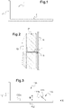
- bracket 1 As seen in figures 1 and 2 .
- Such a bracket 1 consists of a fixing plate 2 designed to be fixed to the wall and a plug-in plate 3 in one piece with said fixing plate. This plug-in plate 3 extends perpendicularly from the fixing plate 2 to give the whole an L shape.
- the insulating panel P is then plugged in or wedged on the edge of the plugging-in plate 3 on said bracket 1 then pressed against the wall M as visible on the figure 2 depicting a top view.
- the bracket is then used to support a metal or wooden structure S allowing the assembly of additional elements such as a second set of secondary frameworks H or directly covering elements of the type (façade facings of any kind, cassettes, clapboard, cladding, plasterboard, etc.)
- brackets have the disadvantage of not allowing the insulating panel to be held against tilting.
- the insulating panel is capable, under the effect of its own weight, of tilting, thus creating an air space between the insulating panel and the wall.
- This tilting causes, firstly, a variation in the performance of the insulation of the final system due to the air gap created between the wall M and the insulating panel P since the contact surface of the latter with the wall decreases and n is more continuous
- this tilting can lead to greater damage such as, for example, tearing of a possible vapor barrier film or a possible rain barrier film associated with said insulating panel or a deformation of said bracket following a poor distribution of the stress exerted by said insulating panel.
- the present invention therefore proposes to solve these drawbacks by providing a bracket for mounting insulating panels allowing better support against tilting and more reliable contact of the insulating panel against the wall.
- the invention relates to a method according to claim 1, an assembly according to claim 5, and a bracket according to claim 6, said bracket for laying an insulating panel on a wall of a wall comprising, between others, a fixing plate intended to be fixed to said wall and a holding plate, said holding plate extending substantially perpendicularly to said fixing plate in order to hold said insulating panel, said bracket further comprising means for holding anti - tilting arranged to prevent the insulating panel from tilting on itself.
- This invention advantageously makes it possible to provide a bracket provided with means for retaining the panel when the latter tends to tilt under its own weight or because of forces due to the wind or to its handling on site. Indeed, the anti-tipping holding means tend to exert a resistance and/or constraint preventing such a tipping.
- said anti-tipping holding means comprise at least one tooth extending projecting from one face of said plug-in plate, in particular perpendicularly from said plug-in plate. holding or forming an acute angle with the holding plate in the direction of the fixing plate.
- said anti-tipping holding means comprise at least two teeth arranged at different distances from the fixing plate.
- said anti-tipping holding means comprise at least two teeth arranged parallel to one another.
- each tooth is in the form of a blade.
- the tooth is in the form of a profile extending over at least part of the width of the retaining plate.
- each tooth has the profile of a right-angled triangle having one of its legs facing the fixing plate.
- said anti-tilt holding means comprise at least one flap arranged in a housing, crossing or not, made in the thickness of the holding plate.
- said anti-tipping holding means comprise at least two flaps, each of said flaps being arranged at a particular distance from said fixing plate.
- said anti-tipping holding means comprise at least two flaps arranged side by side at the same distance from said fixing plate.
- the anti-tipping holding means are integral with the holding plate.
- said anti-tipping holding means are attached to said holding plate.
- said retaining plate is provided with an opening in which a support is attached, said anti-tipping retaining means being arranged on said support.
- the bracket further comprises anti-sagging holding means comprising at least one anti-sagging surface generated by a blade extending from the holding plate so as to substantially perpendicular and horizontal relative to the wall of the wall on which the bracket is fixed.
- the insulating panel is plugged into the bracket.
- the bracket passes through the entire thickness of the insulating panel.
- the anti-tilt means are located, at least in part, on the outside of the insulating panel and cooperate with one face of the insulating panel (its face opposite the wall) to hold the panel and prevent it from tilting.
- said at least one insulating panel is plugged into said bracket.
- said bracket comprises at least two flaps arranged side by side at the same distance from said fixing plate, said bracket being arranged to be in contact with two insulating panels, the flaps being pivoted so that each flap maintains an insulating panel .
- each insulating panel is held by two brackets, for two insulating panels placed side by side, the brackets are fixed to the wall to be staggered, some brackets skewering an insulating panel while other brackets are arranged between two insulating panels.
- the application relates to an unclaimed method of lining a wall, comprising the laying of at least one thickness of insulating panel and comprising the assembly of a lining frame by fixing supports on the plates holding the brackets, and the fixing lining panels on said supports.
- the invention proceeds from the inventive general idea of providing a bracket for fixing a secondary structure on a wall making it possible to facilitate the installation of an insulator or insulating panel and to prevent the insulator from unexpected tilting.
- This bracket 100 comprises a fixing plate 101 intended to be fixed to a wall M and a holding plate 102.
- This holding plate 102 extends substantially perpendicularly from the fixing plate 101, in a so-called longitudinal direction X of the square.
- the bracket 100 can then have an L-shape or a T-shape.
- the fixing plate 101 and the retaining plate 102 can be one-piece or not.
- a lateral direction Y of the bracket is defined as a direction orthogonal to the longitudinal direction X and parallel to the retaining plate 102.
- a transverse plane of the square is a plane orthogonal to the longitudinal direction X.
- This bracket 100 or the various plates 101, 102 may be made of a material of the plastic type, a composite material, a metal or one of its alloys, or of wood.
- This bracket 100 is used for fixing to a wall of a wall M at least one insulating panel P of the glass wool or rock wool type, that is to say made of fibrous materials.
- the insulating panel P can be in the form of a plate or in the form of a roll.
- the bracket 100 can be fixed to the wall M so that the retaining plate 102 extends substantially or completely in a horizontal plane or, preferably, substantially or completely in a vertical plane.
- the bracket 100 can also be arranged for mounting a dubbing frame (not shown) by attaching supports S (visible in figure 9 ) on the retaining plates 102 of the brackets 100.
- this bracket 100 is provided with anti-tilt holding means 110.
- These anti-tilt holding means 110 are arranged to prevent the insulating panel P from tilting on itself and disturbing the insulating function of said insulating panel P once it is plugged in.
- the anti-tipping holding means 110 comprise at least one tooth 111.
- This tooth 111 is arranged on the holding plate 102 and, more particularly, on one of its faces 102a. This tooth 111 projects over a face 102a of said retaining plate 102, in particular perpendicularly from said retaining plate 102 or forms an acute angle with the retaining plate in the direction of the fixing plate.
- This tooth 111 has a profile such that it offers resistance to the displacement of said insulating panel P.
- a profile corresponding to this problem is, for example and without limitation, a triangular profile having the shape of a right triangle.
- This tooth 111 in the shape of a right triangle is then arranged to have one of its cathetes 111a opposite the fixing plate 101.
- the tooth 111 penetrates said panel insulator P via its hypotenuse offering a minimum of resistance to racking-in.
- the hold is ensured by said catheter 111a facing the fixing plate 101.
- this catheter 111a which extends perpendicularly to the retaining plate 102, offers a surface generating a resistance preventing the insulating panel P from tilting.
- This tooth 111 may be in one piece with the retaining plate 102 or added to the latter. In this case, it may be made of a different material.
- provision may be made to have one or more teeth 111 arranged on one or the other of the faces 102a of the retaining plate 102.
- the tooth 111' is in the form of a blade extending perpendicular to one of the faces 102a of the retaining plate 102.
- This blade configuration advantageously makes it possible to offer a sufficiently low resistance so as not to hinder the skewering of the insulating panel P while providing sufficient resistance preventing said insulating panel P from tipping over.
- the bracket 100 comprises at least two parallel teeth 111'. This variant advantageously makes it possible to increase the resistance to tipping without however making racking-in more difficult.
- the tooth is in the form of a profile 111" of triangular section extending over all or part of the width of said retaining plate 102.
- the profile 111" is of constant section in its main direction, which corresponds in the species to the Y lateral direction of the square.
- the dimension of the profile in this main direction is typically greater than the dimensions of its section.
- the length L of the profile is greater than the dimensions of the sides a, b, c of its section.
- This second embodiment has the advantage of presenting a larger surface facing the insulating panel P once the latter has been plugged in and therefore of offering better resistance to tilting.
- this profile 111" is designed to have a lower height than the tooth(s) 111' of the first embodiment. This lower height makes it possible to obtain a smaller frontal surface during racking-in while keeping a surface area of resistance to significant tilting. lateral direction of the square.
- This first embodiment using teeth 111 operates in the following way visible to figures 7 to 9 .
- the operator first fixes the bracket 100 to the wall M. Then, he takes the insulating panel P and pins it on said bracket 100.
- the insulating panel P can be previously and locally incised to facilitate pinning. He skewers the insulating panel P by exerting pressure on it until the tooth 111 passes through said insulating panel P and is visible. Therefore, he can release the pressure he exerts on said insulating panel P, the latter tending to resume its initial volume.
- the insulating panel P then comes into contact with the tooth 111.
- the latter because of its design and its configuration, offers, through its cathetus 111a facing the fixing plate 101, a resistance to the panel.
- the tooth 111 is arranged at a distance from the fixing plate 101 allowing it to prevent the whole of the insulating panel P from resuming its initial volume.
- the tooth is on the outside of the insulating panel and cooperates with one face of the insulating panel (its face opposite the wall). This makes it possible to exert a constraint on said insulating panel P improving the maintenance.
- the teeth 111 of the bracket 100 are arranged to be positioned at different distances from the fixing plate 101. It is understood by this that teeth 111 or series of teeth 111 parallel between they are positioned so that each tooth 111 or series of teeth 111 is at a particular distance from the fixing plate 101.
- each tooth 111 or series of teeth is used for fixing a particular insulating panel P as shown in figure 11 .
- the tooth 111 closest to the fixing plate 101 is used to hold in place a first panel P1 plugged into said bracket 100.
- a second insulating panel P2 is plugged in so as to come into contact with the first insulating panel P1, the second nearest tooth 111 being used to hold this second insulating panel P2 in place and so on.
- the distance between the fixing plate 101 and the first tooth 111 and the interval between the different teeth 111 are calculated to be identical or not to allow the installation of insulating panels Pi of the same thickness or not.
- This configuration can also be used to improve the holding of said insulating panel P or to allow the bracket to be used with panels of different thicknesses while ensuring that the panel is held from the outside by the anti-tipping means.
- the tooth 111 furthest from the fixing plate 101 is used to cross said insulating panel P and hold it while the intermediate tooth(s) 111, that is to say closer to the fixing 101, are used to be found in the thickness of said insulating panel P. In this case, they provide additional support by providing resistance inside the insulating panel P.
- the anti-tipping holding means 110 comprise at least one flap 112.
- the flap 112 may be arranged in a housing 103, crossing or not, made in the thickness of the retaining plate 102 or extend from a stud 106 arranged on said retaining plate 102 as visible in the figures 13a to 13d . In the case of the flap 112 arranged in a housing 103 of the retaining plate 102, the flap 112 may be cut or pre-cut.
- the flap 112 is made of the same material as said bracket 100.
- this stud 106 may be integral with the retaining plate 102 or attached thereto.
- the flap 112 is made of a material other than that of said bracket 100.
- the flap 112 is arranged on a support 104 attached to the retaining plate 102, via for example, an opening 105 made in said retaining plate 102.
- This support 104 comprises the housing 103' or the stud 106'.
- the support 104 is fixed by gluing, welding, brazing, riveting or any other possible method on said bracket.
- This embodiment makes it possible to have a flap 112 made of a material having different characteristics from that in which the bracket 100 is made. It is possible, for example, to imagine a bracket 100 made of a rigid material such as metal or ceramic while having a flap 112 made of an elastic, deformable material, such as plastic.
- This position of the flap 112 relative to the holding plate 102 makes it possible to operate the holding function.
- the operator releases the pressure which he exerts on the insulating panel P.
- This release causes a reaction of said insulating panel P which tends to resume its initial volume.
- the insulating panel P tending to return to its initial position comes into contact with the flap 112.
- the flap 112 has a surface blocking the resumption, by said insulating panel P, of its initial shape as visible at figure 17 .
- the distal end of the flap is directed towards the fixing plate, and the flap operates like a leaf spring which, once in its position substantially perpendicular to the retaining plate (deployed position), forms an anti -return stressing the insulating panel in compression.
- the bracket 100 will include at least two flaps 112.
- the flap 112 is divided into at least two parts 112a.
- This division of the flap 112 into two parts 112a allows them to extend oppositely.
- this first configuration allows the two constituent parts 112a of the flap 112 to be manipulated independently. In this way, it is possible for the parts 112a of the flap 112 to be manipulated to be placed on either side of the retaining plate 102 as seen in figure 20b .
- This possibility advantageously makes it possible to increase the length of the support surface, the latter being for example doubled. The support offered by this first configuration is therefore improved.
- the flaps 112 are mounted side by side so as to be at the same distance from the fixing plate 101.
- This alternative assembly consists of placing the bracket 100 according to the invention between two insulating panels P.
- the insulating panels P are no longer plugged in but simply in contact with said brackets 100. This contact is made between one of the faces of the retaining plate 102 and the edge/thickness of said insulating panel P.
- bracket 100 it then becomes possible to have two insulating panels P arranged next to each other with at least one bracket 100 arranged between them so that the insulating panels P are on either side of the retaining plate 102 as seen at figures 22a and 22b .
- This arrangement advantageously makes it possible to act on the flaps 112, 112a so that they deploy on either side of the retaining plate 102.
- the same bracket 100 can then help to maintain two different insulating panels P1, P2.
- This alternative mounting also works in the case of insulating panels P mounted one above the other.
- This alternative assembly also works in the case of brackets 100 provided with teeth 111.
- brackets 100 may be fixed to the wall so that certain brackets 100 interlock the insulating panel(s) P while other brackets 100 are arranged between two insulation panels P and be only in contact.
- the brackets 100 can thus be staggered.
- the shutters 112 are mounted so as to be at a different distance from the fixing plate 101.
- This second configuration makes it possible, as desired, to have the possibility of plugging in insulating panels P of different thicknesses (ie. the square is adapted to receive different thicknesses of insulating panels, arranged in a single layer on the wall) or to plug several insulating panels P onto the same bracket 100.
- a first insulating panel P is plugged in and then held by a flap 112 placed in a substantially vertical position with respect to the holding plate 102. Then, a second insulating panel P is plugged in so as to be in contact with the first panel insulation P. Pressure is exerted on the second insulating panel P so that the manipulation of a second component 112 can be done.
- This manipulation consists of placing the second flap 112 in a substantially perpendicular position with respect to the retaining plate. Following this, the pressure exerted on the second insulating panel is released so that it tends to resume its initial volume. This tendency is stopped by the flap which blocks the tilting of the insulating panel.
- each flap being composed of at least two parts 112a.
- the bracket 100 according to the invention further comprises anti-sagging holding means 120.
- These anti-sagging holding means 120 comprise at least one anti-sagging surface.
- this surface is generated by a strip 121 extending from the retaining plate 102 perpendicularly and horizontally relative to the wall of the wall M on which the bracket 100 is fixed.
- This anti-sagging surface advantageously makes it possible to provide a surface on which the insulating panel P can, in part, rest so as to prevent it from collapsing on itself.
- This anti-sagging surface will be chosen to be as large as possible without interfering with racking-in.
- This surface may be flat, convex or concave.
- this anti-sagging surface will be generated by a blade 120 extending in the same plane as the tooth 111 of the first embodiment.
- the front surface of this blade 121 generating the anti-sagging surface and the front surface of the holding tooth 111 of the first embodiment during racking-in merge at least in part. This configuration thus makes it possible to have the smallest possible frontal surface and therefore the least resistance during racking-in.
- This blade generating the anti-sag surface will preferably have a trapezoidal shape.
- anti-sagging surfaces it is possible to have several anti-sagging surfaces.
- the maintenance of the panel is optimal when the total contact width of the anti-tipping means in at least one transverse plane of the bracket located at a particular distance from the fixing plate, is greater than 1 cm. It is understood that this contact width corresponds to the width over which the insulating panel is effectively retained by the anti-tipping means.
- the anti-tipping means located in said transverse plane are preferably intended to hold the panel from the outside, cooperating with its face opposite the wall.
- total contact width of the anti-tilt means is meant, where appropriate, the sum of the widths (measured in the lateral direction) of the elements constituting the anti-tilt means (shutters, teeth) in the same transverse plane of the bracket.
- the anti-tipping means comprise, in the lateral direction, a succession of teeth in the form of blades of the type illustrated for example on the figures 4 or 5 , one or more profiles of the type illustrated for example on the figure 6 , one or more flaps of the type illustrated for example on the figure 12 , 18 , 20a .
- the height of the anti-tipping means is preferably at least 5 mm.
- the anti-tilt means are teeth, as on the figure 3 and 6
- this height corresponds to the height H of legs 111a.
- the anti-tipping means are shutters, as for example on the figure 12
- this height corresponds to the maximum height of the flap in the deployed position, in other words to the length of the flap measured between its fixed proximal end 112b and its free distal end 112c.
Landscapes
- Engineering & Computer Science (AREA)
- General Engineering & Computer Science (AREA)
- Physics & Mathematics (AREA)
- Architecture (AREA)
- Mechanical Engineering (AREA)
- Acoustics & Sound (AREA)
- Electromagnetism (AREA)
- Civil Engineering (AREA)
- Structural Engineering (AREA)
- Finishing Walls (AREA)
- Vehicle Interior And Exterior Ornaments, Soundproofing, And Insulation (AREA)
Applications Claiming Priority (2)
| Application Number | Priority Date | Filing Date | Title |
|---|---|---|---|
| FR1662548A FR3060623B1 (fr) | 2016-12-15 | 2016-12-15 | Equerre de fixation d'un panneau isolant |
| PCT/FR2017/053570 WO2018109399A1 (fr) | 2016-12-15 | 2017-12-14 | Equerre de fixation d'un panneau isolant |
Publications (2)
| Publication Number | Publication Date |
|---|---|
| EP3555384A1 EP3555384A1 (fr) | 2019-10-23 |
| EP3555384B1 true EP3555384B1 (fr) | 2022-04-20 |
Family
ID=58401741
Family Applications (1)
| Application Number | Title | Priority Date | Filing Date |
|---|---|---|---|
| EP17822001.8A Active EP3555384B1 (fr) | 2016-12-15 | 2017-12-14 | Equerre de fixation d'un panneau isolant |
Country Status (5)
| Country | Link |
|---|---|
| EP (1) | EP3555384B1 (da) |
| DK (1) | DK3555384T3 (da) |
| ES (1) | ES2921232T3 (da) |
| FR (1) | FR3060623B1 (da) |
| WO (1) | WO2018109399A1 (da) |
Families Citing this family (3)
| Publication number | Priority date | Publication date | Assignee | Title |
|---|---|---|---|---|
| FR3093523B1 (fr) * | 2019-03-06 | 2021-06-04 | Michel Dufresne | Dispositif et procédé pour la pose d'une isolation intérieure. |
| DE102022134713A1 (de) | 2022-12-23 | 2024-07-04 | Saint-Gobain Isover G+H Aktiengesellschaft | Befestigungsset für eine hinterlüftete Fassade |
| EP4575115A1 (en) * | 2023-12-21 | 2025-06-25 | Hilti Aktiengesellschaft | Air gap shield |
Citations (1)
| Publication number | Priority date | Publication date | Assignee | Title |
|---|---|---|---|---|
| WO2016094955A1 (en) * | 2014-12-19 | 2016-06-23 | Hwh Green Hot Water Pty Ltd | Wall cladding system and fastener |
Family Cites Families (4)
| Publication number | Priority date | Publication date | Assignee | Title |
|---|---|---|---|---|
| SE395941B (sv) * | 1974-04-25 | 1977-08-29 | Fast Devel Ab | Festelement for fastsettning av skiv-, platt- eller mattformigt genomstickbart material, i synnerhet isolationsmaterial, vid ett underlag |
| DE3335702A1 (de) * | 1983-10-01 | 1985-04-11 | Schürmann & Hilleke GmbH, 5982 Neuenrade | Aus einem stahlblechstreifen geformtes befestigungselement wie nagel od. dgl. |
| DE9010503U1 (de) * | 1990-07-13 | 1990-09-20 | Trümper, Hans-Jürgen, 5227 Windeck | Befestigungswinkel |
| FR2987421B1 (fr) * | 2012-02-28 | 2014-12-05 | Lr Etanco Atel | Patte d'accrochage d'elements d'isolation. |
-
2016
- 2016-12-15 FR FR1662548A patent/FR3060623B1/fr active Active
-
2017
- 2017-12-14 EP EP17822001.8A patent/EP3555384B1/fr active Active
- 2017-12-14 WO PCT/FR2017/053570 patent/WO2018109399A1/fr not_active Ceased
- 2017-12-14 DK DK17822001.8T patent/DK3555384T3/da active
- 2017-12-14 ES ES17822001T patent/ES2921232T3/es active Active
Patent Citations (1)
| Publication number | Priority date | Publication date | Assignee | Title |
|---|---|---|---|---|
| WO2016094955A1 (en) * | 2014-12-19 | 2016-06-23 | Hwh Green Hot Water Pty Ltd | Wall cladding system and fastener |
Also Published As
| Publication number | Publication date |
|---|---|
| ES2921232T3 (es) | 2022-08-22 |
| DK3555384T3 (da) | 2022-06-20 |
| WO2018109399A1 (fr) | 2018-06-21 |
| FR3060623A1 (fr) | 2018-06-22 |
| EP3555384A1 (fr) | 2019-10-23 |
| FR3060623B1 (fr) | 2022-08-12 |
Similar Documents
| Publication | Publication Date | Title |
|---|---|---|
| WO2010037938A2 (fr) | Procede de pose de panneaux sandwich | |
| EP3555384B1 (fr) | Equerre de fixation d'un panneau isolant | |
| CA2385268C (fr) | Structure acoustique de batiment | |
| EP2791440B1 (fr) | Système d'isolation thermique avec appuis intermédiaires pour maintenir des panneaux piv et procédé d'assemblage associé | |
| EP0764749A1 (fr) | Dispositif de support d'un élément en porte à faux vis-à-vis de la façade verticale d'un mur rideau d'un batiment ou construction analogue | |
| EP0271400B1 (fr) | Revêtement de façade à lame d'air ventilée | |
| EP2634324A1 (fr) | Patte pour l'accrochage d'éléments d'isolation sur un support | |
| EP3347545A1 (fr) | Dispositif de maintien d'un élément de parement a distance d'une membrane pare-vapeur et système constructif a double armature comprenant un tel dispositif | |
| EP3610094B1 (fr) | Equerre de fixation d'un panneau isolant | |
| FR2930315A1 (fr) | Dispositif pour le raccordement de deux elements profiles selon un angle quelconque. | |
| EP3017121A2 (fr) | Profilé à retour et languettes et entretoise associée | |
| EP3810866B1 (fr) | Procédé et kit de réalisation d'un parement pour une structure | |
| EP0636752A1 (fr) | Ensemble à panneaux sandwich destiné principalement au bardage de bâtiments | |
| EP3916168B1 (fr) | Dispositif d'entretoisement pour le doublage d'une paroi | |
| EP3372752B1 (fr) | Ensemble d'ancrage destiné à ancrer à travers une ouverture une portion de paroi sèche prédécoupée | |
| FR2657380A1 (fr) | Agrafe pour la mise en place d'un habillage sur un profile presentant au moins une aile. | |
| FR2743595A1 (fr) | Porte blindee perfectionnee | |
| FR2988753A1 (fr) | Dispositif de montage et de fixation de panneaux de revetement | |
| WO2016108025A1 (fr) | Procédé d'isolation, suspente et ensemble associés | |
| WO2015082776A1 (fr) | Dispositif de cloison murale coupe-feu et ensemble de cloison murale avec bloc-porte comprenant un tel dispositif | |
| FR2896002A1 (fr) | Accessoire pour la pose de panneaux sandwich et de panneaux isolants et procede de pose utilisant cet accessoire | |
| WO2015086650A1 (fr) | Dispositif de maintien d'une presse contre un objet | |
| EP3916169A1 (fr) | Accessoire d'entretoisement pour le doublage d'une paroi | |
| FR2885376A1 (fr) | Systeme mecanique d'alignement de panneaux multicouches | |
| FR2997111A1 (fr) | Lambris panneau avec cadre et panneau de remplissage. |
Legal Events
| Date | Code | Title | Description |
|---|---|---|---|
| STAA | Information on the status of an ep patent application or granted ep patent |
Free format text: STATUS: UNKNOWN |
|
| STAA | Information on the status of an ep patent application or granted ep patent |
Free format text: STATUS: THE INTERNATIONAL PUBLICATION HAS BEEN MADE |
|
| PUAI | Public reference made under article 153(3) epc to a published international application that has entered the european phase |
Free format text: ORIGINAL CODE: 0009012 |
|
| STAA | Information on the status of an ep patent application or granted ep patent |
Free format text: STATUS: REQUEST FOR EXAMINATION WAS MADE |
|
| 17P | Request for examination filed |
Effective date: 20190715 |
|
| AK | Designated contracting states |
Kind code of ref document: A1 Designated state(s): AL AT BE BG CH CY CZ DE DK EE ES FI FR GB GR HR HU IE IS IT LI LT LU LV MC MK MT NL NO PL PT RO RS SE SI SK SM TR |
|
| AX | Request for extension of the european patent |
Extension state: BA ME |
|
| DAV | Request for validation of the european patent (deleted) | ||
| DAX | Request for extension of the european patent (deleted) | ||
| RAP1 | Party data changed (applicant data changed or rights of an application transferred) |
Owner name: SAINT-GOBAIN ISOVER |
|
| STAA | Information on the status of an ep patent application or granted ep patent |
Free format text: STATUS: EXAMINATION IS IN PROGRESS |
|
| 17Q | First examination report despatched |
Effective date: 20200722 |
|
| RIC1 | Information provided on ipc code assigned before grant |
Ipc: E04B 1/76 20060101AFI20210421BHEP Ipc: F16B 5/06 20060101ALI20210421BHEP |
|
| GRAP | Despatch of communication of intention to grant a patent |
Free format text: ORIGINAL CODE: EPIDOSNIGR1 |
|
| STAA | Information on the status of an ep patent application or granted ep patent |
Free format text: STATUS: GRANT OF PATENT IS INTENDED |
|
| INTG | Intention to grant announced |
Effective date: 20211110 |
|
| GRAS | Grant fee paid |
Free format text: ORIGINAL CODE: EPIDOSNIGR3 |
|
| GRAA | (expected) grant |
Free format text: ORIGINAL CODE: 0009210 |
|
| STAA | Information on the status of an ep patent application or granted ep patent |
Free format text: STATUS: THE PATENT HAS BEEN GRANTED |
|
| AK | Designated contracting states |
Kind code of ref document: B1 Designated state(s): AL AT BE BG CH CY CZ DE DK EE ES FI FR GB GR HR HU IE IS IT LI LT LU LV MC MK MT NL NO PL PT RO RS SE SI SK SM TR |
|
| REG | Reference to a national code |
Ref country code: GB Ref legal event code: FG4D Free format text: NOT ENGLISH |
|
| REG | Reference to a national code |
Ref country code: CH Ref legal event code: EP |
|
| REG | Reference to a national code |
Ref country code: DE Ref legal event code: R096 Ref document number: 602017056325 Country of ref document: DE |
|
| REG | Reference to a national code |
Ref country code: IE Ref legal event code: FG4D Free format text: LANGUAGE OF EP DOCUMENT: FRENCH |
|
| REG | Reference to a national code |
Ref country code: AT Ref legal event code: REF Ref document number: 1485238 Country of ref document: AT Kind code of ref document: T Effective date: 20220515 |
|
| REG | Reference to a national code |
Ref country code: DK Ref legal event code: T3 Effective date: 20220613 |
|
| REG | Reference to a national code |
Ref country code: FI Ref legal event code: FGE |
|
| REG | Reference to a national code |
Ref country code: SE Ref legal event code: TRGR |
|
| REG | Reference to a national code |
Ref country code: NL Ref legal event code: FP |
|
| REG | Reference to a national code |
Ref country code: LT Ref legal event code: MG9D |
|
| REG | Reference to a national code |
Ref country code: NO Ref legal event code: T2 Effective date: 20220420 |
|
| REG | Reference to a national code |
Ref country code: ES Ref legal event code: FG2A Ref document number: 2921232 Country of ref document: ES Kind code of ref document: T3 Effective date: 20220822 |
|
| REG | Reference to a national code |
Ref country code: AT Ref legal event code: MK05 Ref document number: 1485238 Country of ref document: AT Kind code of ref document: T Effective date: 20220420 |
|
| PG25 | Lapsed in a contracting state [announced via postgrant information from national office to epo] |
Ref country code: PT Free format text: LAPSE BECAUSE OF FAILURE TO SUBMIT A TRANSLATION OF THE DESCRIPTION OR TO PAY THE FEE WITHIN THE PRESCRIBED TIME-LIMIT Effective date: 20220822 Ref country code: LT Free format text: LAPSE BECAUSE OF FAILURE TO SUBMIT A TRANSLATION OF THE DESCRIPTION OR TO PAY THE FEE WITHIN THE PRESCRIBED TIME-LIMIT Effective date: 20220420 Ref country code: HR Free format text: LAPSE BECAUSE OF FAILURE TO SUBMIT A TRANSLATION OF THE DESCRIPTION OR TO PAY THE FEE WITHIN THE PRESCRIBED TIME-LIMIT Effective date: 20220420 Ref country code: GR Free format text: LAPSE BECAUSE OF FAILURE TO SUBMIT A TRANSLATION OF THE DESCRIPTION OR TO PAY THE FEE WITHIN THE PRESCRIBED TIME-LIMIT Effective date: 20220721 Ref country code: BG Free format text: LAPSE BECAUSE OF FAILURE TO SUBMIT A TRANSLATION OF THE DESCRIPTION OR TO PAY THE FEE WITHIN THE PRESCRIBED TIME-LIMIT Effective date: 20220720 Ref country code: AT Free format text: LAPSE BECAUSE OF FAILURE TO SUBMIT A TRANSLATION OF THE DESCRIPTION OR TO PAY THE FEE WITHIN THE PRESCRIBED TIME-LIMIT Effective date: 20220420 |
|
| PG25 | Lapsed in a contracting state [announced via postgrant information from national office to epo] |
Ref country code: RS Free format text: LAPSE BECAUSE OF FAILURE TO SUBMIT A TRANSLATION OF THE DESCRIPTION OR TO PAY THE FEE WITHIN THE PRESCRIBED TIME-LIMIT Effective date: 20220420 Ref country code: PL Free format text: LAPSE BECAUSE OF FAILURE TO SUBMIT A TRANSLATION OF THE DESCRIPTION OR TO PAY THE FEE WITHIN THE PRESCRIBED TIME-LIMIT Effective date: 20220420 Ref country code: LV Free format text: LAPSE BECAUSE OF FAILURE TO SUBMIT A TRANSLATION OF THE DESCRIPTION OR TO PAY THE FEE WITHIN THE PRESCRIBED TIME-LIMIT Effective date: 20220420 Ref country code: IS Free format text: LAPSE BECAUSE OF FAILURE TO SUBMIT A TRANSLATION OF THE DESCRIPTION OR TO PAY THE FEE WITHIN THE PRESCRIBED TIME-LIMIT Effective date: 20220820 |
|
| REG | Reference to a national code |
Ref country code: DE Ref legal event code: R097 Ref document number: 602017056325 Country of ref document: DE |
|
| PG25 | Lapsed in a contracting state [announced via postgrant information from national office to epo] |
Ref country code: SM Free format text: LAPSE BECAUSE OF FAILURE TO SUBMIT A TRANSLATION OF THE DESCRIPTION OR TO PAY THE FEE WITHIN THE PRESCRIBED TIME-LIMIT Effective date: 20220420 Ref country code: SK Free format text: LAPSE BECAUSE OF FAILURE TO SUBMIT A TRANSLATION OF THE DESCRIPTION OR TO PAY THE FEE WITHIN THE PRESCRIBED TIME-LIMIT Effective date: 20220420 Ref country code: RO Free format text: LAPSE BECAUSE OF FAILURE TO SUBMIT A TRANSLATION OF THE DESCRIPTION OR TO PAY THE FEE WITHIN THE PRESCRIBED TIME-LIMIT Effective date: 20220420 Ref country code: EE Free format text: LAPSE BECAUSE OF FAILURE TO SUBMIT A TRANSLATION OF THE DESCRIPTION OR TO PAY THE FEE WITHIN THE PRESCRIBED TIME-LIMIT Effective date: 20220420 Ref country code: CZ Free format text: LAPSE BECAUSE OF FAILURE TO SUBMIT A TRANSLATION OF THE DESCRIPTION OR TO PAY THE FEE WITHIN THE PRESCRIBED TIME-LIMIT Effective date: 20220420 |
|
| PLBE | No opposition filed within time limit |
Free format text: ORIGINAL CODE: 0009261 |
|
| STAA | Information on the status of an ep patent application or granted ep patent |
Free format text: STATUS: NO OPPOSITION FILED WITHIN TIME LIMIT |
|
| 26N | No opposition filed |
Effective date: 20230123 |
|
| PG25 | Lapsed in a contracting state [announced via postgrant information from national office to epo] |
Ref country code: AL Free format text: LAPSE BECAUSE OF FAILURE TO SUBMIT A TRANSLATION OF THE DESCRIPTION OR TO PAY THE FEE WITHIN THE PRESCRIBED TIME-LIMIT Effective date: 20220420 |
|
| PG25 | Lapsed in a contracting state [announced via postgrant information from national office to epo] |
Ref country code: SI Free format text: LAPSE BECAUSE OF FAILURE TO SUBMIT A TRANSLATION OF THE DESCRIPTION OR TO PAY THE FEE WITHIN THE PRESCRIBED TIME-LIMIT Effective date: 20220420 |
|
| P01 | Opt-out of the competence of the unified patent court (upc) registered |
Effective date: 20230421 |
|
| GBPC | Gb: european patent ceased through non-payment of renewal fee |
Effective date: 20221214 |
|
| PG25 | Lapsed in a contracting state [announced via postgrant information from national office to epo] |
Ref country code: LU Free format text: LAPSE BECAUSE OF NON-PAYMENT OF DUE FEES Effective date: 20221214 |
|
| PG25 | Lapsed in a contracting state [announced via postgrant information from national office to epo] |
Ref country code: IE Free format text: LAPSE BECAUSE OF NON-PAYMENT OF DUE FEES Effective date: 20221214 Ref country code: GB Free format text: LAPSE BECAUSE OF NON-PAYMENT OF DUE FEES Effective date: 20221214 |
|
| PG25 | Lapsed in a contracting state [announced via postgrant information from national office to epo] |
Ref country code: HU Free format text: LAPSE BECAUSE OF FAILURE TO SUBMIT A TRANSLATION OF THE DESCRIPTION OR TO PAY THE FEE WITHIN THE PRESCRIBED TIME-LIMIT; INVALID AB INITIO Effective date: 20171214 |
|
| PG25 | Lapsed in a contracting state [announced via postgrant information from national office to epo] |
Ref country code: CY Free format text: LAPSE BECAUSE OF FAILURE TO SUBMIT A TRANSLATION OF THE DESCRIPTION OR TO PAY THE FEE WITHIN THE PRESCRIBED TIME-LIMIT Effective date: 20220420 |
|
| PG25 | Lapsed in a contracting state [announced via postgrant information from national office to epo] |
Ref country code: MK Free format text: LAPSE BECAUSE OF FAILURE TO SUBMIT A TRANSLATION OF THE DESCRIPTION OR TO PAY THE FEE WITHIN THE PRESCRIBED TIME-LIMIT Effective date: 20220420 |
|
| PG25 | Lapsed in a contracting state [announced via postgrant information from national office to epo] |
Ref country code: MC Free format text: LAPSE BECAUSE OF FAILURE TO SUBMIT A TRANSLATION OF THE DESCRIPTION OR TO PAY THE FEE WITHIN THE PRESCRIBED TIME-LIMIT Effective date: 20220420 |
|
| PG25 | Lapsed in a contracting state [announced via postgrant information from national office to epo] |
Ref country code: MC Free format text: LAPSE BECAUSE OF FAILURE TO SUBMIT A TRANSLATION OF THE DESCRIPTION OR TO PAY THE FEE WITHIN THE PRESCRIBED TIME-LIMIT Effective date: 20220420 |
|
| PG25 | Lapsed in a contracting state [announced via postgrant information from national office to epo] |
Ref country code: MT Free format text: LAPSE BECAUSE OF FAILURE TO SUBMIT A TRANSLATION OF THE DESCRIPTION OR TO PAY THE FEE WITHIN THE PRESCRIBED TIME-LIMIT Effective date: 20220420 |
|
| PG25 | Lapsed in a contracting state [announced via postgrant information from national office to epo] |
Ref country code: BG Free format text: LAPSE BECAUSE OF FAILURE TO SUBMIT A TRANSLATION OF THE DESCRIPTION OR TO PAY THE FEE WITHIN THE PRESCRIBED TIME-LIMIT Effective date: 20220420 |
|
| PG25 | Lapsed in a contracting state [announced via postgrant information from national office to epo] |
Ref country code: BG Free format text: LAPSE BECAUSE OF FAILURE TO SUBMIT A TRANSLATION OF THE DESCRIPTION OR TO PAY THE FEE WITHIN THE PRESCRIBED TIME-LIMIT Effective date: 20220420 |
|
| PGFP | Annual fee paid to national office [announced via postgrant information from national office to epo] |
Ref country code: NL Payment date: 20251112 Year of fee payment: 9 |
|
| REG | Reference to a national code |
Ref country code: CH Ref legal event code: U11 Free format text: ST27 STATUS EVENT CODE: U-0-0-U10-U11 (AS PROVIDED BY THE NATIONAL OFFICE) Effective date: 20260101 |
|
| PGFP | Annual fee paid to national office [announced via postgrant information from national office to epo] |
Ref country code: DE Payment date: 20251104 Year of fee payment: 9 |
|
| PGFP | Annual fee paid to national office [announced via postgrant information from national office to epo] |
Ref country code: NO Payment date: 20251210 Year of fee payment: 9 |
|
| PGFP | Annual fee paid to national office [announced via postgrant information from national office to epo] |
Ref country code: IT Payment date: 20251121 Year of fee payment: 9 Ref country code: FI Payment date: 20251211 Year of fee payment: 9 Ref country code: DK Payment date: 20251212 Year of fee payment: 9 |
|
| PGFP | Annual fee paid to national office [announced via postgrant information from national office to epo] |
Ref country code: FR Payment date: 20251110 Year of fee payment: 9 |
|
| PGFP | Annual fee paid to national office [announced via postgrant information from national office to epo] |
Ref country code: TR Payment date: 20251205 Year of fee payment: 9 Ref country code: BE Payment date: 20251117 Year of fee payment: 9 |
|
| PGFP | Annual fee paid to national office [announced via postgrant information from national office to epo] |
Ref country code: SE Payment date: 20251112 Year of fee payment: 9 |
|
| PGFP | Annual fee paid to national office [announced via postgrant information from national office to epo] |
Ref country code: ES Payment date: 20260112 Year of fee payment: 9 |
|
| PGFP | Annual fee paid to national office [announced via postgrant information from national office to epo] |
Ref country code: CH Payment date: 20260101 Year of fee payment: 9 |