EP2634324A1 - Patte pour l'accrochage d'éléments d'isolation sur un support - Google Patents
Patte pour l'accrochage d'éléments d'isolation sur un support Download PDFInfo
- Publication number
- EP2634324A1 EP2634324A1 EP13155767.0A EP13155767A EP2634324A1 EP 2634324 A1 EP2634324 A1 EP 2634324A1 EP 13155767 A EP13155767 A EP 13155767A EP 2634324 A1 EP2634324 A1 EP 2634324A1
- Authority
- EP
- European Patent Office
- Prior art keywords
- support
- blade
- insulation
- elements
- fastening
- Prior art date
- Legal status (The legal status is an assumption and is not a legal conclusion. Google has not performed a legal analysis and makes no representation as to the accuracy of the status listed.)
- Withdrawn
Links
- 238000009413 insulation Methods 0.000 claims abstract description 33
- 238000000034 method Methods 0.000 claims abstract description 10
- 230000002512 anti-withdrawal effect Effects 0.000 claims abstract description 5
- 238000005192 partition Methods 0.000 claims description 3
- 238000002955 isolation Methods 0.000 description 7
- 239000000463 material Substances 0.000 description 7
- 239000011810 insulating material Substances 0.000 description 4
- 238000012550 audit Methods 0.000 description 2
- 239000002131 composite material Substances 0.000 description 2
- 230000001681 protective effect Effects 0.000 description 2
- 229910000831 Steel Inorganic materials 0.000 description 1
- 241000826860 Trapezium Species 0.000 description 1
- 240000008042 Zea mays Species 0.000 description 1
- 238000004026 adhesive bonding Methods 0.000 description 1
- 238000005452 bending Methods 0.000 description 1
- 239000011449 brick Substances 0.000 description 1
- 239000000470 constituent Substances 0.000 description 1
- 239000011491 glass wool Substances 0.000 description 1
- 238000009434 installation Methods 0.000 description 1
- 239000002184 metal Substances 0.000 description 1
- 239000011490 mineral wool Substances 0.000 description 1
- 230000000149 penetrating effect Effects 0.000 description 1
- 230000035515 penetration Effects 0.000 description 1
- 238000007665 sagging Methods 0.000 description 1
- 239000010959 steel Substances 0.000 description 1
- 238000003466 welding Methods 0.000 description 1
Images

Classifications
-
- E—FIXED CONSTRUCTIONS
- E04—BUILDING
- E04B—GENERAL BUILDING CONSTRUCTIONS; WALLS, e.g. PARTITIONS; ROOFS; FLOORS; CEILINGS; INSULATION OR OTHER PROTECTION OF BUILDINGS
- E04B1/00—Constructions in general; Structures which are not restricted either to walls, e.g. partitions, or floors or ceilings or roofs
- E04B1/62—Insulation or other protection; Elements or use of specified material therefor
- E04B1/74—Heat, sound or noise insulation, absorption, or reflection; Other building methods affording favourable thermal or acoustical conditions, e.g. accumulating of heat within walls
- E04B1/76—Heat, sound or noise insulation, absorption, or reflection; Other building methods affording favourable thermal or acoustical conditions, e.g. accumulating of heat within walls specifically with respect to heat only
- E04B1/762—Exterior insulation of exterior walls
- E04B1/7629—Details of the mechanical connection of the insulation to the wall
-
- E—FIXED CONSTRUCTIONS
- E04—BUILDING
- E04B—GENERAL BUILDING CONSTRUCTIONS; WALLS, e.g. PARTITIONS; ROOFS; FLOORS; CEILINGS; INSULATION OR OTHER PROTECTION OF BUILDINGS
- E04B1/00—Constructions in general; Structures which are not restricted either to walls, e.g. partitions, or floors or ceilings or roofs
- E04B1/62—Insulation or other protection; Elements or use of specified material therefor
- E04B1/74—Heat, sound or noise insulation, absorption, or reflection; Other building methods affording favourable thermal or acoustical conditions, e.g. accumulating of heat within walls
- E04B1/76—Heat, sound or noise insulation, absorption, or reflection; Other building methods affording favourable thermal or acoustical conditions, e.g. accumulating of heat within walls specifically with respect to heat only
- E04B1/7608—Heat, sound or noise insulation, absorption, or reflection; Other building methods affording favourable thermal or acoustical conditions, e.g. accumulating of heat within walls specifically with respect to heat only comprising a prefabricated insulating layer, disposed between two other layers or panels
- E04B1/7612—Heat, sound or noise insulation, absorption, or reflection; Other building methods affording favourable thermal or acoustical conditions, e.g. accumulating of heat within walls specifically with respect to heat only comprising a prefabricated insulating layer, disposed between two other layers or panels in combination with an air space
- E04B1/7616—Heat, sound or noise insulation, absorption, or reflection; Other building methods affording favourable thermal or acoustical conditions, e.g. accumulating of heat within walls specifically with respect to heat only comprising a prefabricated insulating layer, disposed between two other layers or panels in combination with an air space with insulation-layer locating devices combined with wall ties
Definitions
- the invention is in the field of devices for attaching insulation elements on a vertical building surface. It also relates to a method for hanging such insulating elements on such a surface.
- the thermal and / or sound insulation of a building can be done from the outside or from the inside. Many specific devices have been proposed to fix the insulating elements to the wall according to these two methods.
- An insulating process from the inside consists of inserting the insulating elements on parts previously fixed to the wall, whether it is a load-bearing wall or a partition, then raising a bulkhead, for example in bricks, along the exposed face of the insulating elements, with or without a blade of air between the two.
- a flat fastening tab comprising three parts separated by two fold lines, a part intended to be glued to the wall, a part intended to serve as a support for the insulating elements, and an end part intended to perforate an element. insulation and to be folded parallel to the wall. These brackets are complicated to implement.
- a pin for hanging flexible elements comprising a hooking element capable of pivoting according to a axis of rotation to be placed at about 90 ° from the spindle.
- the pivot is a point of weakness of the device.
- the insulation elements are for example panels of light material such as glass wool or rock wool, which can also be in the form of rollers, which perform a function of thermal insulation and / or sound.
- the bracket is primarily intended for insulating installation from the inside, but could be used for exterior insulation.
- the support can be any type of substantially vertical support in a building, such as load-bearing wall, partition wall, masonry or metal pillar or other.
- the support means of the latching lug is intended to penetrate the insulating elements, and consequently provide support for these elements in the mass of the insulating material.
- Insulating materials are in fact generally soft and light materials that can be pierced by a fastening element element, but they do not have sufficient rigidity to maintain themselves vertically, it is necessary to provide support means to prevent them from sinking under their own weight.
- the anti-removal means act inside the insulating elements by taking hold of the material that constitutes these elements and not on one side of these elements.
- the fastening means may comprise a substantially flat plate for fixing it to the support, forming a heel.
- the plate may comprise at least one through opening.
- the support means may further comprise a blade rigidly connected by a first end to said plate substantially orthogonal manner.
- the blade extends substantially orthogonally with respect to the heel, the blade and the heel being rigidly connected by a connecting fold.
- the blade therefore comprises a direction of longitudinal extension orthogonal to the heel, a first end connected to the heel at a second free end, and a direction of transverse extension, substantially parallel to the heel, this direction of transverse extension being limited by two edges.
- the fact that the blade has a direction of transverse extension gives the hooking tab, when the blade is disposed substantially horizontally, a sufficient surface to support the insulating elements and prevent them from sagging under their own control. weight.
- the blade may comprise a second free end opposite said first end, this second end having a tip.
- This tip is intended to perforate the insulation and the protective sheets between which it is held when it is placed against the wall.
- said anti-withdrawal means may comprise at least one protruding protrusion protruding from an edge of the blade and directed towards said first end of said blade, in the manner of a harpoon barb.
- the insulating elements When the insulating elements are applied by the operator on the hooking lugs, they are first pierced by the tip of the blade of the hooking lugs, then traversed by the blade, the tip-shaped protrusions are not not opposing their penetration in view of their orientation.
- these protuberances are designed to catch in the material of the insulating elements and possibly the protective sheets, and thus prevent these elements from moving away from the wall once they have been applied to them. They avoid a withdrawal movement once the insulating elements skewered on the blade of the latching lug. They act in this material like the barbs of a harpoon or the barb of a hook.
- the hooking tab may comprise a row of barbs on each of the edges of the blade.
- the hooking lug can then be symmetrical.
- attachment lug when the thickness of the insulating elements is greater than the length of the blade in that it does not constitute a thermal bridge: the second pointed end of the blade does not exceed the material insulating.
- This connecting part can take different forms depending on the shape of a cross section of the blade.
- the attachment lugs When fixing, the attachment lugs must be oriented about an orthogonal axis to the support so that the support means provided for the insulation elements performs its function better. This objective is achieved when the projection on a horizontal plane of the support means of the attachment tabs has a maximum surface to provide support for the insulating elements and they do not sag under their own weight.
- the hooking lug has a heel and a blade connected by a binding fold, this objective is achieved when it is fixed to the wall so that the binding fold is substantially horizontal, the heel is located above or below the blade.
- the thickness of the insulating elements is strictly greater than the length of the blade of said fastening tabs.
- the fastening tabs thus avoid forming a thermal bridge.
- the bulkhead can be raised against the insulation elements; it then participates in maintaining these elements by friction. But advantageously, the bulkhead can be raised by providing an air gap between the insulating elements and the against wall, so as to ventilate the space between the support and the bulkhead. In this case, the latching lugs fully play their role because the insulating elements are no longer held by friction against the bulkhead.
- the support is a wall having an outer face and the insulation elements are hung on the inner face of this wall.
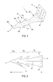
- the attachment tab 1 for insulation elements illustrated in Figures 1 to 3 It generally has the shape of an L. It comprises a plate 10 forming a heel, which represents the small branch of the L, and a blade 20, rigidly connected by a connecting fold 30 which extends along one side of the plate 10.
- the blade has a longitudinal extension D, in a direction orthogonal to the plate 10 and a transverse extension parallel to the plate 10.
- the hooking lug 1 is metallic, for example steel. It is for example manufactured by stamping.
- the heel 10 is in the form of a flat plate of substantially square shape with beveled corners.
- the heel 10 has nine through openings 10a, 10b ... 10i to facilitate its attachment to the wall by screwing or riveting.
- the blade 20 has a first end 20a, at the connecting fold 30 of the blade and the heel 10 and a second free end 20b.
- the first end 20a has a transverse extension equal to the length of the connecting fold 30.
- the second end 20b has a tip 21 which is intended to pierce the insulating material and its protection.
- the blade 20 of the attachment tab illustrated in figure 2 extends in two planes P1, P2, connected by a longitudinal stop 25, these two planes being angularly offset by an angle A substantially equal to 120 °, which gives good resistance to bending to the blade.
- the hooking lug 1 has a longitudinal plane of symmetry passing through this stop 25.
- the edges 22, 23 each comprise two points, respectively 22a, 22b and 23a, 23b.
- these tips are inclined towards the first end 20a of the blade - and thus towards the heel 10 - by an angle B substantially equal to 35 °, and they are respectively located in the planes P1, P2 of the blade.
- the length of the tips, measured from the edge of the blade 20 is not small in front of the length D of the blade, about 15%, nor in front of its width, about 100%, so that these points constitute barbs or barbs and generally give the blade 20 a harpoon shape. These barbs or barbs thus cling to the material within the insulation elements and prevent their withdrawal once they have been skewered on the blade 20.
Landscapes
- Physics & Mathematics (AREA)
- Engineering & Computer Science (AREA)
- Architecture (AREA)
- Acoustics & Sound (AREA)
- Electromagnetism (AREA)
- Civil Engineering (AREA)
- Structural Engineering (AREA)
- Building Environments (AREA)
Abstract
L'invention concerne une patte (1) pour l'accrochage d'éléments d'isolation sur un support sensiblement vertical comportant :
- un moyen de fixation (10) de la patte au support,
- un moyen d'appui (20) des éléments d'isolation, ledit moyen d'appui étant rigidement relié audit moyen de fixation et prévu pour pénétrer les éléments d'isolation,
le moyen d'appui (20) comportant des moyens d'anti-retrait (22a, 22b, 23a, 23b) pour les éléments d'isolation, lesdits moyens d'anti-retrait étant prévus pour agir à l'intérieur des éléments d'isolation. L'invention porte également sur un procédé d'isolation utilisant la patte d'accrochage.
Description
- L'invention se situe dans le domaine des dispositifs d'accrochage d'éléments d'isolation sur une surface verticale de bâtiment. Elle porte également sur un procédé pour accrocher de tels éléments d'isolation sur une telle surface.
- L'isolation thermique et/ou phonique d'un bâtiment peut s'effectuer par l'extérieur ou par l'intérieur. De nombreux dispositifs spécifiques ont été proposés pour fixer les éléments isolants au mur selon ces deux procédés.
- Un procédé d'isolation par l'intérieur consiste à embrocher les éléments isolants sur des pièces préalablement fixées au mur, qu'il s'agisse d'un mur porteur ou d'une cloison, puis à élever une contre cloison, par exemple en briques, le long de la face apparente des éléments isolants, en ménageant ou non une lame d'air entre les deux.
- De
FR 2 677 411 FR 2 268 971 - De
FR 2 928 949 - De
US 4 244 269 on connaît une attache pour accrocher des éléments d'isolation, comportant deux parties, une lame pointue et une pièce de blocage. Les côtés de la lame comportent des encoches dans lesquelles la pièce de blocage s'encliquette parallèlement au mur. Cette attache est également compliquée à mettre en oeuvre et elle comporte deux éléments. - L'invention vise à supprimer ces inconvénients. A cet effet, elle propose une patte pour l'accrochage d'éléments d'isolation sur un support sensiblement vertical pouvant comporter :
- un moyen de fixation de la patte au support,
- un moyen d'appui des éléments d'isolation, ledit moyen d'appui étant rigidement relié audit moyen de fixation et prévu pour pénétrer les éléments d'isolation,
- Les éléments d'isolation sont par exemple des panneaux de matériau léger tel que laine de verre ou laine de roche, pouvant également se présenter sous forme de rouleaux, qui remplissent une fonction d'isolation thermique et/ou phonique. La patte d'accrochage est principalement destinée à la pose d'isolant par l'intérieur, mais elle pourrait être utilisée pour l'isolation par l' extérieur.
- Le support peut être tout type de support sensiblement vertical dans un bâtiment, tel que mur porteur, cloison, pilier en maçonnerie ou métallique ou autre.
- Le moyen d'appui de la patte d'accrochage est prévu pour pénétrer les éléments d'isolation, et en conséquence procurer un appui à ces éléments dans la masse du matériau isolant. Les matériaux isolants sont en effet généralement des matériaux souples et légers qui peuvent se laisser transpercer par un élément de patte d'accrochage, mais ils n'ont pas une rigidité suffisante pour se maintenir verticalement par eux mêmes, il est nécessaire de leur procurer des moyens d'appui pour éviter qu'ils s'affaissent sous leur propre poids.
- Les moyens d'anti-retrait agissent à l'intérieur des éléments d'isolation en prenant prise sur le matériau qui constitue ces éléments et non sur une face de ces éléments.
- Le moyen de fixation peut comporter une plaque sensiblement plane, destiné à sa fixation au support, formant talon.
- Tout mode de fixation est envisageable, tel que collage, vissage, rivetage, soudage... En vue de faciliter le vissage ou le rivetage, la plaque peut comporter au moins une ouverture traversante.
- Le moyen d'appui peut en outre comporter une lame rigidement reliée par une première extrémité à ladite plaque de façon sensiblement orthogonale.
- La lame s'étend sensiblement orthogonalement par rapport au talon, la lame et le talon étant rigidement reliés par un pli de liaison. La lame comporte donc une direction d'extension longitudinale orthogonale au talon, d'une première extrémité reliée au talon à une seconde extrémité libre, et une direction d'extension transversale, sensiblement parallèle au talon, cette direction d'extension transversale étant limitée par deux bords. Le fait que la lame possède une direction d'extension transversale donne à la patte d'accrochage, lorsque la lame est disposée sensiblement horizontalement, une surface suffisante pour soutenir les éléments d'isolation et éviter qu'ils ne s'affaissent sous leur propre poids.
- La lame peut comporter une seconde extrémité libre opposée à ladite première extrémité, cette seconde extrémité comportant une pointe.
- Cette pointe est destinée à perforer l'isolant et les feuilles de protection entre lesquelles il est maintenu au moment de sa mise en place contre le mur.
- Avantageusement, lesdits moyens d'anti-retrait peuvent comprendre au moins une excroissance en forme de pointe saillante d'un bord de la lame et dirigée vers ladite première extrémité de ladite lame, à la façon d'une barbelure de harpon.
- Lorsque les éléments isolants sont appliqués par l'opérateur sur les pattes d'accrochage, ils sont tout d'abord percés par la pointe de la lame des pattes d'accrochage, puis traversés par la lame, les excroissances en forme de pointe ne s'opposant pas à leur pénétration compte tenu de leur orientation. En revanche, ces excroissances sont prévues pour s'accrocher dans le matériau des éléments isolant et éventuellement les feuilles de protection, et ainsi éviter que ces éléments s'écartent du mur une fois qu'ils y ont été appliqués. Elles évitent un mouvement de retrait une fois les éléments isolants embrochés sur la lame de la patte d'accrochage. Ils agissent dans ce matériau comme les barbelures d'un harpon ou l'ardillon d'un hameçon.
- Avantageusement la patte d'accrochage peut comporter une rangée de barbelures sur chacun des bords de la lame.
- La patte d'accrochage peut alors être symétrique.
- Un avantage particulier est procuré par la patte d'accrochage lorsque l'épaisseur des éléments isolants est supérieure à la longueur de la lame en ce qu'elle ne constitue pas de pont thermique : la deuxième extrémité pointue de la lame ne dépasse pas du matériau isolant.
- La lame peut présenter plusieurs profils transversaux :
- elle peut être plane, auquel cas son profil transversal est simplement une droite qui se confond, au niveau de sa jonction avec le talon, avec le pli de liaison,
- elle peut s'étendre, sur au moins une partie de sa longueur à partir de ladite deuxième extrémité, selon deux plans décalés d'un angle prédéterminé et reliés par une arrête.
- Ceci n'exclut pas d'autres formes de section transversale, pourvu que la lame comporte toujours une certaine extension transversale pour servir d'appui au matériau isolant.
- Dans le cas où la lame n'est pas plane, il doit exister une partie de raccordement entre la lame et le talon, qui est plan. Cette partie de raccordement peut prendre différentes formes en fonction de la forme d'une section transversale de la lame.
- L'invention porte également sur un procédé d'isolation d'un support sensiblement vertical, pouvant comporter les étapes consistant à :
- fixer audit support une pluralité de pattes d'accrochage selon l'invention, en les orientant autour d'un axe orthogonal au support de façon que la surface de la projection sur un plan horizontal dudit moyen d'appui soit maximale, de façon à former un appui pour un élément d'isolation,
- embrocher au moins un élément d'isolation sur lesdites pattes d'accrochage,
- élever une contre cloison le long de la face extérieure des éléments d'isolation.
- Lors de leur fixation, les pattes d'accrochage doivent être orientées autour d'un axe orthogonal au support de façon que le moyen d'appui prévu pour les éléments d'isolation remplisse au mieux sa fonction. Cet objectif est atteint lorsque la projection sur un plan horizontal du moyen d'appui des pattes d'accrochage présente une surface maximale pour procurer un appui aux éléments isolants et qu'ils ne s'affaissent pas sous leur propre poids. Quand la patte d'accrochage présente un talon et une lame reliés par un pli de liaison, cet objectif est atteint lorsqu'elle est fixée au mur de façon que le pli de liaison soit sensiblement horizontal, que le talon soit situé au-dessus ou au-dessous de la lame.
- Avantageusement, l'épaisseur des éléments d'isolation est strictement supérieure à la longueur de la lame desdites pattes d'accrochage.
- Les pattes d'accrochage évitent ainsi de constituer un pont thermique.
- La contre cloison peut être élevée tout contre les éléments d'isolation ; celle-ci participe alors au maintien de ces éléments par frottement. Mais avantageusement, la contre cloison peut être élevée en ménageant une lame d'air entre les éléments d'isolation et la contre cloison, de façon à ventiler l'espace entre le support et la contre cloison. Dans ce cas les pattes d'accrochage jouent pleinement leur rôle car les éléments isolants ne sont plus maintenus par frottement contre la contre cloison.
- Avantageusement, le support est un mur ayant une face extérieure et les éléments d'isolation sont accrochés sur la face intérieure de ce mur.
- Des modes de réalisation et des variantes seront décrits ci-après, à titre d'exemples non limitatifs, avec référence aux dessins annexés dans lesquels :
- La
figure 1 représente une patte d'accrochage en perspective, - La
figure 2 représente une patte d'accrochage vue de dessus, - La
figure 3 représente une patte d'accrochage en vue de face. - La patte d'accrochage 1 pour éléments d'isolation illustrée en
figures 1 à 3 présente globalement la forme d'un L. Elle comporte une plaque 10 formant talon, qui représente la petite branche du L, et une lame 20, rigidement reliés par un pli de liaison 30 qui s'étend selon un côté de la plaque 10. La lame possède une extension longitudinale D, selon une direction orthogonale à la plaque 10 et une extension transversale parallèle à la plaque 10. La patte d'accrochage 1 est métallique, par exemple en acier. Elle est par exemple fabriquée par emboutissage. - Le talon 10 se présente sous la forme d'une plaque plane de forme sensiblement carrée aux coins biseautés. Le talon 10 comporte neuf ouvertures traversantes 10a, 10b... 10i pour faciliter sa fixation au mur par vissage ou par rivetage.
- La lame 20 comporte une première extrémité 20a, au niveau du pli de liaison 30 de la lame et du talon 10 et une seconde extrémité libre 20b.
- La première extrémité 20a possède une extension transversale égale à la longueur du pli de liaison 30. En revanche, la seconde extrémité 20b comporte une pointe 21 qui est destinée à percer le matériau isolant et sa protection.
- La lame 20 de la patte d'accrochage illustrée en
figure 2 s'étend selon deux plans P1, P2, reliés par une arrête longitudinale 25, ces deux plans étant angulairement décalés d'un angle A sensiblement égal à 120°, ce qui confère une bonne résistance à la flexion à la lame. La patte d'accrochage 1 possède un plan de symétrie longitudinal passant par cette arrête 25. - La lame 20 comporte deux bords 22, 23, qui s'étendent entre une extrémité respective du pli de liaison 30 et la pointe 21. La lame 20 comporte trois sections longitudinales :
- une première section 20c à partir de la première extrémité 20a, qui va en se rétrécissant et qui a donc globalement la forme d'un trapèze en vue de dessus ; cette première section 20c de la lame comporte une section de raccordement entre le talon 10 qui est plan et la lame 20 qui n'est pas plane, cette section de raccordement comportant deux sections planes p1, p2 qui s'étendent entre le pli de liaison 30 et des lignes de jonction avec les plans P1, P2 de la lame,
- une deuxième section 20d dont les bords sont sensiblement parallèles,
- une troisième section 20e dont les bords convergent vers la seconde extrémité en forme de pointe 21.
- Au niveau de la deuxième section 20d de la lame, les bords 22, 23 comportent chacun deux pointes, respectivement 22a, 22b et 23a, 23b. Comme il est visible en
figures 2 et3 , ces pointes sont inclinées vers la première extrémité 20a de la lame - et donc vers le talon 10 - d'un angle B sensiblement égal à 35°, et elles sont situées respectivement dans les plans P1, P2 de la lame. La longueur des pointes, mesurée depuis le bord de la lame 20, n'est pas faible devant la longueur D de la lame, environ 15%, ni devant sa largeur, environ 100%, de sorte que ces pointes constituent des barbelures ou ardillons et confèrent globalement à la lame 20 une forme de harpon. Ces barbelures ou ardillons s'accrochent donc au matériau au sein des éléments d'isolation et évitent leur retrait une fois qu'ils ont été embrochés sur la lame 20. - Bien entendu, d'autres modes de réalisation sont couverts par l'invention :
- la plaque 10 pourrait prendre une autre forme, par exemple rectangulaire ou semi circulaire, et être dépourvue d'ouvertures traversantes pour sa fixation, par exemple si la patte d'accrochage est prévue pour être collée, ou simplement comporter un crochet,
- la lame 20 pourrait être plane, ou elle pourrait comporter une section transversale en arc de cercle, ou elle pourrait définir un volume, par exemple conique ou parallélépipédique,
- l'extension transversale de la première extrémité 20a pourrait ne pas être égale à la longueur du pli de liaison 30,
- les bords de la première section 20c pourraient être parallèles, inversement les bords de la deuxième section 20d pourraient ne pas être parallèles,
- les pointes ou barbelures 22a, 22b et 23a, 23b pourraient ne pas être coplanaires avec la lame ou les plans angulairement décalés P1, P2 qui constituent la lame, ni coplanaires entre elles,
- la patte d'accrochage pourrait comporter un nombre différent de pointes, et elles pourraient être situées sur des bords non parallèles de la lame 20,
- la patte d'accrochage pourrait ne pas posséder de plan de symétrie longitudinal,
- elle pourrait ne pas être métallique, mais réalisée par exemple en matériau composite.
Claims (14)
- Patte (1) pour l'accrochage d'éléments d'isolation sur un support sensiblement vertical comportant :- un moyen de fixation (10) de la patte au support,- un moyen d'appui (20) des éléments d'isolation, ledit moyen d'appui étant rigidement relié audit moyen de fixation et prévu pour pénétrer les éléments d'isolation,
caractérisée en ce que le moyen d'appui comporte des moyens d'anti-retrait (22a, 22b, 23a, 23b) pour les éléments d'isolation, lesdits moyens d'anti-retrait étant prévus pour agir à l'intérieur des éléments d'isolation. - Patte d'accrochage selon la revendication 1,
caractérisée en ce que ledit moyen de fixation comporte une plaque (10) sensiblement plane. - Patte d'accrochage selon la revendication 2,
caractérisée en ce que ladite plaque (10) comporte au moins une ouverture traversante (10a à 10i). - Patte d'accrochage selon l'une des revendications 2 ou 3, caractérisée en ce que ledit moyen d'appui comporte une lame (20) rigidement reliée par une première extrémité (20a) à ladite plaque (10) de façon sensiblement orthogonale.
- Patte d'accrochage selon la revendication 4,
caractérisée en ce que ladite lame (20) comporte une seconde extrémité (20b) libre opposée à ladite première extrémité (20a), cette seconde extrémité comportant une pointe (21). - Patte d'accrochage selon la revendication 5,
caractérisée en ce que lesdits moyens d'anti-retrait (22a, 22b, 23a, 23b) comprennent au moins une excroissance en forme de pointe saillante d'un bord (22, 23) de la lame et dirigée vers ladite première extrémité (20a) de ladite lame (20), à la façon d'une barbelure de harpon. - Patte d'accrochage selon la revendication 6,
caractérisée en ce qu'elle comporte une rangée de barbelures sur chacun des bords (22, 23) de la lame. - Patte d'accrochage selon l'une des revendications 4 à 7,
caractérisée en ce que ladite lame (20) est plane. - Patte d'accrochage selon l'une des revendications 4 à 7,
caractérisée en ce que sur au moins une partie de sa longueur à partir de ladite seconde extrémité (20b), ladite lame (20) s'étend selon deux plans décalés d'un angle prédéterminé (A) et reliés par une arrête (25). - Patte d'accrochage selon l'une des revendications précédentes, caractérisée en ce qu'elle est métallique.
- Procédé d'isolation d'un support sensiblement vertical,
caractérisé en ce qu'il comporte les étapes consistant à :- fixer audit support une pluralité de pattes d'accrochage (1) selon l'une des revendications 1 à 10, en les orientant autour d'un axe orthogonal au support de façon que la surface de la projection sur un plan horizontal dudit moyen d'appui (20) soit maximale, de façon à former un appui pour un élément d'isolation,- embrocher au moins un élément d'isolation sur lesdites pattes d'accrochage,- élever une contre cloison le long de la face extérieure des éléments d'isolation. - Procédé d'isolation d'un support selon la revendication 11, caractérisé en ce que l'épaisseur desdits éléments d'isolation est strictement supérieure à la longueur de la lame desdites pattes d'accrochage (1).
- Procédé d'isolation d'un support selon la revendication 11 ou 12, caractérisé en ce que la contre cloison est élevée en ménageant une lame d'air entre les éléments d'isolation et la contre cloison.
- Procédé d'isolation d'un support selon l'une des revendications 11 à 13,
caractérisé en ce que le support est un mur ayant une face extérieure, et en ce que les éléments d'isolation sont accrochés sur la face intérieure de ce mur.
Applications Claiming Priority (1)
| Application Number | Priority Date | Filing Date | Title |
|---|---|---|---|
| FR1251774A FR2987421B1 (fr) | 2012-02-28 | 2012-02-28 | Patte d'accrochage d'elements d'isolation. |
Publications (1)
| Publication Number | Publication Date |
|---|---|
| EP2634324A1 true EP2634324A1 (fr) | 2013-09-04 |
Family
ID=47710057
Family Applications (1)
| Application Number | Title | Priority Date | Filing Date |
|---|---|---|---|
| EP13155767.0A Withdrawn EP2634324A1 (fr) | 2012-02-28 | 2013-02-19 | Patte pour l'accrochage d'éléments d'isolation sur un support |
Country Status (2)
| Country | Link |
|---|---|
| EP (1) | EP2634324A1 (fr) |
| FR (1) | FR2987421B1 (fr) |
Cited By (4)
| Publication number | Priority date | Publication date | Assignee | Title |
|---|---|---|---|---|
| WO2016094955A1 (fr) * | 2014-12-19 | 2016-06-23 | Hwh Green Hot Water Pty Ltd | Système de revêtement mural, et élément de fixation |
| DE102016118491A1 (de) | 2015-11-10 | 2017-05-11 | WIDO–PROFIL – Spółka z ograniczoną odpowiedzialnością | Verfahren zur Montage von Isolierplatten an einer Gebäudewand und Satz von Elementen zur Montage von Isolierplatten an einer Gebäudewand |
| WO2018109399A1 (fr) * | 2016-12-15 | 2018-06-21 | Saint-Gobain Isover | Equerre de fixation d'un panneau isolant |
| WO2018189486A1 (fr) * | 2017-04-14 | 2018-10-18 | Saint-Gobain Isover | Equerre de fixation d'un panneau isolant |
Citations (9)
| Publication number | Priority date | Publication date | Assignee | Title |
|---|---|---|---|---|
| FR2268971A1 (fr) | 1974-04-25 | 1975-11-21 | Fast Devel Ab | |
| US4244269A (en) | 1978-10-30 | 1981-01-13 | Transco, Inc. | Prong-type fastener |
| WO1985000397A1 (fr) * | 1983-07-06 | 1985-01-31 | Insulhold, Inc. | Systeme pour soutenir et retenir une isolation |
| DE3335702A1 (de) * | 1983-10-01 | 1985-04-11 | Schürmann & Hilleke GmbH, 5982 Neuenrade | Aus einem stahlblechstreifen geformtes befestigungselement wie nagel od. dgl. |
| CH657652A5 (en) * | 1982-09-23 | 1986-09-15 | Wolfgang Schugk | Retainer for fastening insulating fibre mats - consists of plate with barbed plug inserted into mat |
| FR2677411A1 (fr) | 1991-06-04 | 1992-12-11 | Saint Gobain Isover | Systeme pour la fixation de produits isolants. |
| DE10229115A1 (de) * | 2002-06-28 | 2004-01-29 | Bever Gesellschaft für Befestigungsteile - Verbindungselemente mbH | Zweischaliges Mauerwerk und Verbindungselement dafür |
| WO2006114177A1 (fr) * | 2005-04-26 | 2006-11-02 | Rockwool International A/S | Paroi de cavite et fixation de paroi |
| FR2928949A1 (fr) | 2008-03-21 | 2009-09-25 | Lafarge Platres Sa | Broche pour accrochage d'isolants souples et equipements techniques |
-
2012
- 2012-02-28 FR FR1251774A patent/FR2987421B1/fr active Active
-
2013
- 2013-02-19 EP EP13155767.0A patent/EP2634324A1/fr not_active Withdrawn
Patent Citations (9)
| Publication number | Priority date | Publication date | Assignee | Title |
|---|---|---|---|---|
| FR2268971A1 (fr) | 1974-04-25 | 1975-11-21 | Fast Devel Ab | |
| US4244269A (en) | 1978-10-30 | 1981-01-13 | Transco, Inc. | Prong-type fastener |
| CH657652A5 (en) * | 1982-09-23 | 1986-09-15 | Wolfgang Schugk | Retainer for fastening insulating fibre mats - consists of plate with barbed plug inserted into mat |
| WO1985000397A1 (fr) * | 1983-07-06 | 1985-01-31 | Insulhold, Inc. | Systeme pour soutenir et retenir une isolation |
| DE3335702A1 (de) * | 1983-10-01 | 1985-04-11 | Schürmann & Hilleke GmbH, 5982 Neuenrade | Aus einem stahlblechstreifen geformtes befestigungselement wie nagel od. dgl. |
| FR2677411A1 (fr) | 1991-06-04 | 1992-12-11 | Saint Gobain Isover | Systeme pour la fixation de produits isolants. |
| DE10229115A1 (de) * | 2002-06-28 | 2004-01-29 | Bever Gesellschaft für Befestigungsteile - Verbindungselemente mbH | Zweischaliges Mauerwerk und Verbindungselement dafür |
| WO2006114177A1 (fr) * | 2005-04-26 | 2006-11-02 | Rockwool International A/S | Paroi de cavite et fixation de paroi |
| FR2928949A1 (fr) | 2008-03-21 | 2009-09-25 | Lafarge Platres Sa | Broche pour accrochage d'isolants souples et equipements techniques |
Cited By (6)
| Publication number | Priority date | Publication date | Assignee | Title |
|---|---|---|---|---|
| WO2016094955A1 (fr) * | 2014-12-19 | 2016-06-23 | Hwh Green Hot Water Pty Ltd | Système de revêtement mural, et élément de fixation |
| DE102016118491A1 (de) | 2015-11-10 | 2017-05-11 | WIDO–PROFIL – Spółka z ograniczoną odpowiedzialnością | Verfahren zur Montage von Isolierplatten an einer Gebäudewand und Satz von Elementen zur Montage von Isolierplatten an einer Gebäudewand |
| WO2018109399A1 (fr) * | 2016-12-15 | 2018-06-21 | Saint-Gobain Isover | Equerre de fixation d'un panneau isolant |
| FR3060623A1 (fr) * | 2016-12-15 | 2018-06-22 | Saint-Gobain Isover | Equerre de fixation d'un panneau isolant |
| WO2018189486A1 (fr) * | 2017-04-14 | 2018-10-18 | Saint-Gobain Isover | Equerre de fixation d'un panneau isolant |
| FR3065238A1 (fr) * | 2017-04-14 | 2018-10-19 | Saint-Gobain Isover | Equerre de fixation d'un panneau isolant |
Also Published As
| Publication number | Publication date |
|---|---|
| FR2987421B1 (fr) | 2014-12-05 |
| FR2987421A1 (fr) | 2013-08-30 |
Similar Documents
| Publication | Publication Date | Title |
|---|---|---|
| EP2634324A1 (fr) | Patte pour l'accrochage d'éléments d'isolation sur un support | |
| FR2940988A1 (fr) | Dalle pour plafond | |
| EP2456931B1 (fr) | Fausse paroi comprenant une lisse à double enclenchement | |
| FR2910509A1 (fr) | "revetement mural et piece de stabilisation pour un tel revetement mural" | |
| FR2992017A1 (fr) | Coffre-tunnel incorporant une patte de fixation entre un linteau et le dormant d'une menuiserie | |
| EP3009582A1 (fr) | Dispositif d'entretoisement pour la fixation d'un profilé de support d'une cloison de doublage d'une paroi à isoler | |
| EP3263813A1 (fr) | Dispositif de fixation d'une ferrure dans une rainure en t de menuiserie | |
| EP3555384B1 (fr) | Equerre de fixation d'un panneau isolant | |
| EP2683885B1 (fr) | Profile universel | |
| FR3012489A1 (fr) | Moyen de fixation d'une ossature a une paroi | |
| EP1993419B1 (fr) | Dispositif de fixation pour barre d'accrochage d'ustensiles de cuisine | |
| FR2989396A1 (fr) | Suspente extensible | |
| EP2907630A1 (fr) | Butée amovible pour un outil de coupe de plaque et outil de coupe comportant une telle butée amovible | |
| FR3023573A1 (fr) | Interface de fixation pour coffre de volet | |
| EP2949856B1 (fr) | Coffre-tunnel creusé d'une rainure de logement pour une patte de fixation et incorporant une armature de renfort | |
| EP2575182A1 (fr) | Dispositif de fixation d'au moins un module photovoltaïque sur une structure porteuse, panneau photovoltaïque et ensemble comprenant au moins deux panneaux photovoltaïques équipés chacun d'un tel dispositif | |
| FR2948163A1 (fr) | Dispositif de fixation d'elements distincts sur une structure rigide d'aeronef | |
| EP3485105B1 (fr) | Faux-plafond comprenant des moyens de calage de panneau(x) et procede pour la realisation d'un tel faux-plafond | |
| FR2885971A1 (fr) | Dispositif d'ancrage d'un element structural sur une poutre metallique profilee | |
| FR3093746A1 (fr) | Suspente plate longitudinale | |
| WO2015082776A1 (fr) | Dispositif de cloison murale coupe-feu et ensemble de cloison murale avec bloc-porte comprenant un tel dispositif | |
| EP1832708B1 (fr) | Console pour supporter un arbre de volet roulant, et montage de volet roulant avec une telle console | |
| FR3110924A1 (fr) | Accessoire d'entretoisement pour le doublage d'une paroi | |
| FR2897249A1 (fr) | Presentoir reversible | |
| FR2997111A1 (fr) | Lambris panneau avec cadre et panneau de remplissage. |
Legal Events
| Date | Code | Title | Description |
|---|---|---|---|
| PUAI | Public reference made under article 153(3) epc to a published international application that has entered the european phase |
Free format text: ORIGINAL CODE: 0009012 |
|
| 17P | Request for examination filed |
Effective date: 20130219 |
|
| AK | Designated contracting states |
Kind code of ref document: A1 Designated state(s): AL AT BE BG CH CY CZ DE DK EE ES FI FR GB GR HR HU IE IS IT LI LT LU LV MC MK MT NL NO PL PT RO RS SE SI SK SM TR |
|
| AX | Request for extension of the european patent |
Extension state: BA ME |
|
| STAA | Information on the status of an ep patent application or granted ep patent |
Free format text: STATUS: EXAMINATION IS IN PROGRESS |
|
| STAA | Information on the status of an ep patent application or granted ep patent |
Free format text: STATUS: THE APPLICATION IS DEEMED TO BE WITHDRAWN |
|
| 18D | Application deemed to be withdrawn |
Effective date: 20170321 |