EP3554985B1 - Machine de remplissage permettant de remplir des récipients - Google Patents
Machine de remplissage permettant de remplir des récipients Download PDFInfo
- Publication number
- EP3554985B1 EP3554985B1 EP17808453.9A EP17808453A EP3554985B1 EP 3554985 B1 EP3554985 B1 EP 3554985B1 EP 17808453 A EP17808453 A EP 17808453A EP 3554985 B1 EP3554985 B1 EP 3554985B1
- Authority
- EP
- European Patent Office
- Prior art keywords
- filling
- container
- light
- machine according
- light source
- Prior art date
- Legal status (The legal status is an assumption and is not a legal conclusion. Google has not performed a legal analysis and makes no representation as to the accuracy of the status listed.)
- Active
Links
Images
Classifications
-
- B—PERFORMING OPERATIONS; TRANSPORTING
- B67—OPENING, CLOSING OR CLEANING BOTTLES, JARS OR SIMILAR CONTAINERS; LIQUID HANDLING
- B67C—CLEANING, FILLING WITH LIQUIDS OR SEMILIQUIDS, OR EMPTYING, OF BOTTLES, JARS, CANS, CASKS, BARRELS, OR SIMILAR CONTAINERS, NOT OTHERWISE PROVIDED FOR; FUNNELS
- B67C3/00—Bottling liquids or semiliquids; Filling jars or cans with liquids or semiliquids using bottling or like apparatus; Filling casks or barrels with liquids or semiliquids
- B67C3/007—Applications of control, warning or safety devices in filling machinery
-
- B—PERFORMING OPERATIONS; TRANSPORTING
- B67—OPENING, CLOSING OR CLEANING BOTTLES, JARS OR SIMILAR CONTAINERS; LIQUID HANDLING
- B67C—CLEANING, FILLING WITH LIQUIDS OR SEMILIQUIDS, OR EMPTYING, OF BOTTLES, JARS, CANS, CASKS, BARRELS, OR SIMILAR CONTAINERS, NOT OTHERWISE PROVIDED FOR; FUNNELS
- B67C3/00—Bottling liquids or semiliquids; Filling jars or cans with liquids or semiliquids using bottling or like apparatus; Filling casks or barrels with liquids or semiliquids
- B67C3/02—Bottling liquids or semiliquids; Filling jars or cans with liquids or semiliquids using bottling or like apparatus
- B67C3/22—Details
- B67C3/28—Flow-control devices, e.g. using valves
- B67C3/282—Flow-control devices, e.g. using valves related to filling level control
- B67C3/284—Flow-control devices, e.g. using valves related to filling level control using non-liquid contact sensing means
Definitions
- the invention relates to a filling machine for filling containers.
- Filling machines for filling containers are known in principle. They typically have a transport element which is driven to revolve around a vertical vertical axis and on which a large number of filling stations are provided. A filling element is arranged at a respective filling station, by means of which a controlled feeding of the filling material to be filled into the container is made possible. In particular, filling machines are known which have an output of more than 10,000 containers per hour, in particular more than 50,000 containers per hour.
- free-jet filling machines are known in which the liquid filling material flows to the container to be filled in a free filling material jet in the direction of flow downstream of the liquid valve.
- Very high filling capacities volume of the filled product per unit of time
- attempts are increasingly being made to fill plastic containers, in particular PET bottles, as well as glass containers by means of free-jet filling.
- volumetric measuring methods and measuring methods that directly determine the filling level inside the container to be filled are known.
- the volumetric measuring method the volume of the filling material is measured before it is fed to the container to be filled, so that a defined volume of filling material is fed into it, regardless of the container volume.
- volumetric measuring method or volumetric filling principle is not suitable for glass bottles, since the empty bottle volume in glass bottles is subject to strong fluctuations due to the production process and thus filling bottles with different empty bottle volumes with the same filling volume leads to different filling heights in the bottles. However, this is perceived by consumers as degrading. For this reason, glass bottles are mainly filled with level filling systems that measure the filling level in the container using probes or return gas tubes and, depending on this, activate the liquid valve. However, this leads to lower filling performance.
- the light source is designed to emit light in the direction of the vertical axis of the container or essentially in the direction of the vertical axis of the container.
- the light can be directed from below or from above onto the filling material in the container, which has a positive effect on the level detection in the container.
- the light source is provided below the bottom of the container and/or the light source is provided in the area of the container mouth.
- the lighting can be from above, from below or from one side or from both sides.
- the underside lighting can, for example, be integrated into a container carrier (e.g. bottle plate). The result of this is that the container is advantageously illuminated for the level detection.
- the light source is provided on the side of the filling element that faces the container mouth.
- the light source can be integrated into the valve body of the filling valve contained in the filling element.
- it can be provided in the housing of the filling element in such a way that light is emitted in the direction of the interior of the container.
- the light source has a light guide which protrudes into the interior of the container via the container mouth and by means of which the light emitted by the light source can be supplied to the interior of the container.
- the light guide can be provided at least in sections in the valve body of the liquid valve.
- the light guide can, for example, protrude beyond the free end of the valve body downwards in the direction of the interior of the container and, for example, protrude through the container mouth into the latter.
- the free end of the light guide can come to rest on the free end of the valve body.
- the use of a light guide for the light supply means that the light-emitting element can be provided at a distance from the filling opening of the filling valve, which offers advantages with regard to the maintainability and construction of the filling machine.
- the light source is designed to provide light with a wavelength in the visible range, in the infrared range or to provide light in the UV range.
- a wavelength in the visible range in the infrared range or to provide light in the UV range.
- the filling machine has a large number of filling elements which are provided on a transport element which is driven in a rotating manner. At least one optical detection means in the form of a camera is provided for each filling element, which is permanently assigned to the filling element and is moved along with it in a circumferential manner. As a result, a continuous fill level measurement, in particular at the end of the filling process, can be achieved which is independent of the rotational position of the transport element.
- the light guide has a bundle of light-conducting fibers and the camera is designed to capture the image information supplied through the bundle of light-conducting fibers.
- a light guide constructed in such a way that the image information can be transmitted through the light guide can be used. This enables an endoscope-like detection of the filling level in the container.
- the light guide has at least a first light guide region for supplying light from a light source to the Container interior and at least a second light guide area for transmitting optical information from the container interior to the camera.
- the second light guide area can be formed by a fiber bundle containing a large number of individual fibers.
- the first and second light guide areas preferably run alongside one another, in particular parallel to one another.
- the light guide runs at least in sections in the filling jet of the filling medium. For example, it protrudes from the underside of the valve body and dips into the interior of the container, for example.
- the free end of the light guide facing the container to be filled is provided above the height level defining the desired fill level and at a distance from it, i.e. after the end of the filling process the free end of the light guide is at a distance from the level of the filling material. In this way, an exact filling level measurement can be achieved, since the light guide does not dip into the level of the filling material or the foam, even with foaming filling goods.
- the light source is integrated in the filling element, in particular in the movably arranged valve body or in the housing of the filling element surrounding the valve body, and the optical sensor or camera is provided laterally next to the container to be filled.
- the optical sensor or the camera can either move or be fixed.
- a large number of filling elements are provided, which are designed to fill the container in a free jet. As a result, a high filling capacity can be achieved with precise level measurement at the same time.
- a large number of filling elements are provided, which are designed to fill the containers in one process which the filling material is guided to the inner container wall via at least one flow guide element before or during the flow into the container, and thus flows as a thin filling material film to the container bottom.
- the at least one flow guide element can be, for example, a swirl body or a radiation screen.
- Containers within the meaning of the invention are in particular bottles, cans, barrels or other containers to be filled with a liquid product.
- Optical sensor is understood to mean any sensor by means of which brightness values or light intensity values can be detected.
- the term "camera” is understood to mean a measuring device by which two-dimensional image information (eg by a matrix-like sensor array) can be recorded.
- the image information can in particular include light intensity values and/or color information.
- free jet filling is understood to mean a filling process in which the liquid filling material flows towards the container to be filled from the liquid valve in a free filling jet or filling material jet, with the flow of the filling material not being restricted by guide elements such as deflector screens, swirl bodies, short or long filling tubes is influenced or changed. Jet filling can be done without pressure or under pressure. In the case of pressureless free-jet filling, the container is at ambient pressure, with the container mouth or opening generally not lying against the filling element, but rather being at a distance from the filling element or from a discharge opening provided.
- a gas path establishes a connection between the interior of the container and the environment, which enables pressureless filling.
- the gas contained in the container and displaced by the beverage flowing into the container also escapes into the environment via this gas path.
- the free jet filling takes place under a pressure that deviates from the ambient pressure, the container is pressed with its mouth against the filling element and sealed, the pressure in the interior of the container is adjusted to this pressure, which differs from the ambient pressure, by applying a clamping gas or by applying a negative pressure , which can be both above and below the ambient pressure.
- substantially or “approximately” in the context of the invention means deviations from the exact value in each case by +/-10%, preferably by +/-5% and/or deviations in the form of changes that are insignificant for the function.
- Filling machines of the rotary type have a transport element on which a large number of filling stations, each with a filling element 1, are provided.
- the containers 2 to be filled are fed to the filling machine in an upright position (container mouth aligned upwards) and picked up at a filling station in such a way that the container 2 is filled by the respective filling element 1 while the transport element is rotating.
- the filled container is then removed from the filling station and transported in a suitable manner to the next processing station (e.g. capper).
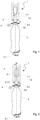
- FIG 1 shows schematically a filling element 1 of a filling machine according to a first embodiment.
- a container 2 is arranged below a filling element 1 shown in section.
- the filling element 1 consists, in a manner known per se, of a valve body 1.1 which is provided in a housing 1.2 so as to be axially displaceable in the vertical direction.
- a valve seat is formed in the housing 2.1, so that when the valve body 1.1 rests against the valve seat, the liquid valve of the Filling element 1 is closed and the liquid valve is opened when the valve body 1.1 is lifted from the valve seat, so that filling material can enter the container 2.
- the filling element 1 is designed in particular for free jet filling of the container 2 .
- the filling of the container 2 can take place when the container mouth 2.2 rests against a sealing surface formed on the filling element 1 or when the container mouth 2.2 is at a distance from the filling element 1.
- the filling machine is designed to detect the fill level inside the container 2 to be filled with optical detection means 4 .
- the optical detection means 4 are provided laterally next to the container 2 to be filled, in particular in such a way that they detect the area in which the target filling height FS of the container 2 should lie.
- the optical detection means 4 can in particular be formed by at least one optical sensor or by a camera.
- the optical detection means 4 can either be stationary and/or moved along with the respective filling element 1 .
- one or more optical detection means 4 can be provided circumferentially around the transport element having the plurality of filling elements 1, by means of which the fill level in the container 2 can be determined.
- a detection means 4 can be permanently assigned to a filling element 1 and moved with it, so that the fill level in the container 2 can be measured during its movement.
- a light source 3 is provided, by means of which light is emitted into the interior of the container.
- the light source 3 is integrated into the valve body 1.1 or provided on it.
- the light source 3 can also be provided in the area of the housing 1.2, in particular at the free end of the housing 1.2 facing the container 2. This ensures that the filling level measurement and the lighting of the interior of the container does not require a probe or the like protruding into the interior of the container, so that the entire free Cross section of the container mouth 2.2 is available for introducing the filling material.
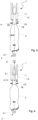
- FIG figure 2 shows a filling element 1 of a filling machine according to a second embodiment.
- the structure of the filling machine according to the second embodiment is essentially identical to the structure of the embodiment described above. Therefore, only the differences between the exemplary embodiments are described below. Otherwise, the statements made above in relation to the first exemplary embodiment also apply to the embodiment according to FIG figure 2 .
- the main difference of the embodiment according to figure 2 according to the embodiment figure 1 is that the light generated by the light source 3 is guided into the interior of the container by means of a light guide 3.1.
- the light guide 3.1 preferably runs at least in sections within the valve body 1.1.
- the light guide 3.1 can protrude downwards over the free end of the valve body 1.1 in the direction of the container 2, but still end within the housing 2.1, ie it cannot protrude beyond the container mouth 2.2 into the container interior.
- the light guide can end at the free end of the valve body 1.1 or protrude into the container interior via the container mouth 2.2. In such a case, however, the ends of the light guides protrude into the interior of the container, preferably above the target filling height FS.
- a bundled light beam can be supplied to the interior of the container, as a result of which greater detection accuracy is achieved.
- FIG. 3 shows a filling element 1 of a filling machine according to a third embodiment.
- the structure of the filling machine according to the third exemplary embodiment is essentially identical to the structure of the exemplary embodiments described above Figures 1 and 2 . Therefore, only the differences between the exemplary embodiments are described below. Otherwise, the statements made above in relation to the first or second exemplary embodiment also apply to the embodiment according to FIG figure 3 .
- the main difference of the embodiment according to figure 3 according to the embodiments Figure 1 and 2 is that the at least partial illumination of the interior of the container is not provided by a light source 3 provided above the container 2, but the light source 3 is provided below the container 2. As a result, the light beams emitted by the light source 3 are guided from below through the container floor 2.1 into the interior of the container. It goes without saying that the container bottom 2.1 is designed to be at least partially transparent for this purpose.
- the optical detection means 4 can in turn be provided laterally next to the container 2, either rotating with the filling element 1 or stationary.
- FIG. 4 shows a fourth embodiment of a filling element 1 of a filling machine.
- the interior of the container is illuminated in the same way as in the exemplary embodiment according to FIG figure 3 from below by means of a light source 3 arranged below the container bottom 2.1 figure 3
- the optical detection unit 4 is not arranged on the side next to the container, but the filling level FS in the container 2 is detected by means of a light guide 3.1, the first free end 3.1.3 of which faces the container mouth 2.2 or through this container mouth 2.2 into the container interior protrudes and is connected to the opposite free end with a camera 6.
- the first free end 3.1.3 of the light guide 3.1 can, as in figure 4 shown end within the housing 1.2 of the filling element or project into the container interior via the container mouth 2.2 in such a way that the free end 3.1.3 ends above the target filling height FS to be reached by the filling material.
- the light guide 3.1 together with the camera 6 forms an endoscope-like detection means, by means of which the fill level in the container 2 can be determined optically.
- the camera 6 is supplied with image information via the light guide 3.1, which is recorded by a sensor array provided inside the camera 6 (eg CCD sensor or the like). This information recorded by the camera 6 is then processed by suitable image processing means, in particular one on one Processing unit provided image processing program processed and based on the filling level of the filling material within the container 2 is determined.
- the light guide 3.1 is designed to transmit image information from the interior of the container to the camera 6. In other words, not only a brightness value or the received light intensity is evaluated by the camera 6, but a spatially resolved image is captured by means of a flat sensor, which has receiving units arranged in a matrix, which convert the incident light into an electrical signal by means of the photo effect.
- the light guide 3.1 can have a fiber bundle with a large number of individual fibers or can be formed by a single light guide containing a glass fiber or a gel or liquid light guide.
- the camera 6 can also be provided on the underside of the valve body 1.1 facing the container 2 or on an element protruding downwards like a probe from the valve body 1.1.
- the image information does not have to be fed to the camera 6 via a light guide 3.1, but the camera 6 records the image information directly in the vicinity of the container mouth 2.2.
- the camera 6 is protected against liquids, in particular provided in an encapsulated manner.
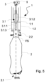
- FIG 5 shows a fifth exemplary embodiment, in which both the illumination of the container interior and the transmission of image information to the camera 6 take place by means of a light guide 3.1.
- the light guide 3.1 has a first light guide area 3.1.1 and a second light guide area 3.1.2.
- the first light guide area 3.1.1 is provided for supplying light from a light source 3 to the interior of the container, i.e. light is coupled into the first light guide area 3.1.1 at an end remote from the container 2 and fed to the container 2 (similar to the exemplary embodiment according to 2 ).
- the light guide preferably runs at least in sections within the valve body 1.1.
- the second light guide area 3.1.2 can in turn have a fiber bundle with a large number of individual fibers or be formed by a single light guide containing a glass fiber or a gel or liquid light guide.
- the first and second light guide areas 3.1.1, 3.1.2 preferably run alongside one another, in particular parallel to one another.
- the light source 3 can emit light in the visible wavelength range, but also light in the infrared range or in the UV wavelength range (eg UV black light), depending on requirements and the application.
Landscapes
- Filling Of Jars Or Cans And Processes For Cleaning And Sealing Jars (AREA)
- Basic Packing Technique (AREA)
Claims (12)
- Machine de remplissage permettant de remplir des contenants (2) avec un produit de remplissage liquide, dans laquelle le niveau de remplissage dans le contenant (2) à remplir peut être déterminé par des moyens de détection optiques, dans laquelle l'espace intérieur de contenant est éclairé au moins en partie par une source de lumière (3), et qu'une caméra (6) ou un guide de lumière (5) relié à une caméra (6) est prévue ou prévu dans la zone de l'élément de remplissage (1), et qu'au moins une unité de calcul avec des moyens de programme de traitement d'image est prévue, au moyen de laquelle la hauteur de remplissage (FS) dans le contenant (2) peut être calculée à partir des informations d'image fournies par la caméra (6) en exécutant un programme de traitement d'image, dans laquelle la source de lumière (3) est prévue dans la zone de l'embouchure de contenant (2.2),
caractérisée en ce que
la machine de remplissage présente une pluralité d'éléments de remplissage (1), qui sont prévus sur un élément de transport entraîné par rotation en périphérie, et que respectivement au moins un moyen de détection optique (4) est prévu sous la forme d'une caméra par élément de remplissage (1), laquelle est associée de manière fixe à l'élément de remplissage (1) et est déplacée conjointement en périphérie. - Machine de remplissage selon la revendication 1, caractérisée en ce que la source de lumière (3) est réalisée pour distribuer de la lumière en direction de l'axe en hauteur de contenant (BHA) ou sensiblement en direction de l'axe en hauteur de contenant (BHA).
- Machine de remplissage selon l'une quelconque des revendications précédentes, caractérisée en ce que la source de lumière (3) est prévue sur le côté, tourné vers l'embouchure de contenant (2.2), de l'élément de remplissage (1).
- Machine de remplissage selon l'une quelconque des revendications précédentes, caractérisée en ce que la source de lumière (3) présente un guide de lumière (3.1), qui dépasse à l'intérieur de l'espace intérieur de contenant par l'intermédiaire de l'embouchure de contenant (2.2) et au moyen duquel la lumière émise par la source de lumière (3) peut être amenée à l'espace intérieur de contenant.
- Machine de remplissage selon l'une quelconque des revendications précédentes, caractérisée en ce que la source de lumière (3) est réalisée pour fournir de la lumière avec une longueur d'onde dans la plage visible, dans la plage infrarouge ou pour fournir de la lumière dans la plage UV.
- Machine de remplissage selon la revendication 4, caractérisée en ce que le guide de lumière (3.1) présente un faisceau de fibres optiques, et que la caméra (6) est réalisée pour détecter les informations d'image amenées par le faisceau de fibres optiques.
- Machine de remplissage selon la revendication 4 ou 6, caractérisée en ce que le guide de lumière (3.1) présente au moins une première plage de guide de lumière pour amener de la lumière depuis une source de lumière (3) vers l'espace intérieur de contenant et au moins une deuxième plage de guide de lumière pour transmettre des informations optiques depuis l'espace intérieur de contenant vers la caméra (6).
- Machine de remplissage selon l'une quelconque des revendications 4 ou 6 ou 7, caractérisée en ce que le guide de lumière (3.1) s'étend au moins par endroits dans le jet de remplissage du milieu de remplissage.
- Machine de remplissage selon l'une quelconque des revendications 4 ou 6 ou 8, caractérisée en ce que l'extrémité libre, tournée vers le contenant à remplir, du guide de lumière (3.1) est prévue soit au-dessus du niveau en hauteur définissant la hauteur de remplissage et à distance de celui-ci soit toutefois sous ledit niveau en hauteur.
- Machine de remplissage selon l'une quelconque des revendications précédentes, caractérisée en ce que la source de lumière (3) est prévue de manière intégrée dans l'élément de remplissage (1), en particulier dans le corps de soupape (1.1) disposé de manière mobile ou dans le boîtier (1.2), entourant le corps de soupape (1.1), de l'élément de remplissage (1), et que la caméra (6) est prévue latéralement à côté du contenant (2) à remplir.
- Machine de remplissage selon l'une quelconque des revendications précédentes, caractérisée en ce qu'une pluralité d'éléments de remplissage (1) sont prévus, qui sont réalisés dans le jet libre pour remplir le contenant (2).
- Machine de remplissage selon l'une quelconque des revendications 1 à 11 précédentes, caractérisée en ce que le guide de lumière (3.1) s'étend au moins en partie l'intérieur de l'espace entouré par le produit de remplissage ou le milieu de remplissage circulant en tant que film de produit de remplissage par l'intermédiaire de la paroi intérieure du contenant vers le fond de contenant.
Priority Applications (1)
| Application Number | Priority Date | Filing Date | Title |
|---|---|---|---|
| SI201731348T SI3554985T1 (sl) | 2016-12-15 | 2017-12-01 | Polnilni stroj za polnjenje vsebnikov |
Applications Claiming Priority (2)
| Application Number | Priority Date | Filing Date | Title |
|---|---|---|---|
| DE102016124446.5A DE102016124446A1 (de) | 2016-12-15 | 2016-12-15 | Füllmaschine sowie Verfahren zum Befüllen von Behältern |
| PCT/EP2017/081136 WO2018108575A1 (fr) | 2016-12-15 | 2017-12-01 | Machine de remplissage et procédé permettant de remplir des récipients |
Publications (2)
| Publication Number | Publication Date |
|---|---|
| EP3554985A1 EP3554985A1 (fr) | 2019-10-23 |
| EP3554985B1 true EP3554985B1 (fr) | 2023-03-08 |
Family
ID=60569918
Family Applications (1)
| Application Number | Title | Priority Date | Filing Date |
|---|---|---|---|
| EP17808453.9A Active EP3554985B1 (fr) | 2016-12-15 | 2017-12-01 | Machine de remplissage permettant de remplir des récipients |
Country Status (4)
| Country | Link |
|---|---|
| EP (1) | EP3554985B1 (fr) |
| DE (1) | DE102016124446A1 (fr) |
| SI (1) | SI3554985T1 (fr) |
| WO (1) | WO2018108575A1 (fr) |
Families Citing this family (1)
| Publication number | Priority date | Publication date | Assignee | Title |
|---|---|---|---|---|
| US20230202824A1 (en) * | 2021-12-29 | 2023-06-29 | Pepsico, Inc. | Managing dispensement of fluid to a receptacle |
Family Cites Families (11)
| Publication number | Priority date | Publication date | Assignee | Title |
|---|---|---|---|---|
| JPS5844559B2 (ja) * | 1977-03-28 | 1983-10-04 | キッコーマン株式会社 | 液体の定量充填装置 |
| DE3605748A1 (de) * | 1986-02-22 | 1987-08-27 | Seitz Enzinger Noll Masch | Fuellrohrloses fuellelement |
| DE3909405A1 (de) | 1988-05-10 | 1989-11-16 | Seitz Enzinger Noll Masch | Fuellelement |
| DE3909398A1 (de) | 1988-05-10 | 1989-11-16 | Seitz Enzinger Noll Masch | Fuellelement |
| DE4239954A1 (de) * | 1992-11-27 | 1994-06-01 | Khs Masch & Anlagenbau Ag | Verfahren zum Abfüllen eines flüssigen Füllgutes in Flaschen sowie Füllmaschine zum Durchführen dieses Verfahrens |
| DE4343750C2 (de) * | 1993-02-27 | 1995-09-21 | Ortmann & Herbst Masch Gmbh | Getränkefüller mit Schaumsteuerung |
| DE4446548B4 (de) | 1994-12-24 | 2005-09-15 | Khs Maschinen- Und Anlagenbau Ag | Verfahren sowie Füllmaschine zum Füllen von Behältern mit einem flüssigen Füllgut |
| DE202005003281U1 (de) * | 2005-03-01 | 2005-10-06 | Krones Ag | Füllstation |
| JP4471286B2 (ja) * | 2005-03-02 | 2010-06-02 | 三菱重工食品包装機械株式会社 | 回転式充填装置 |
| FR2939119A1 (fr) * | 2008-12-01 | 2010-06-04 | Newtec Filling Systems | Dispositif de remplissage d'une bouteille et systeme automatique de remplissage de bouteilles correspondant |
| EP2942322B1 (fr) * | 2014-05-07 | 2016-09-14 | SIDEL S.p.A. CON SOCIO UNICO | Machine de remplissage de récipient avec une meilleure détection d'un niveau de remplissage et procédé associé |
-
2016
- 2016-12-15 DE DE102016124446.5A patent/DE102016124446A1/de not_active Withdrawn
-
2017
- 2017-12-01 SI SI201731348T patent/SI3554985T1/sl unknown
- 2017-12-01 WO PCT/EP2017/081136 patent/WO2018108575A1/fr not_active Ceased
- 2017-12-01 EP EP17808453.9A patent/EP3554985B1/fr active Active
Also Published As
| Publication number | Publication date |
|---|---|
| SI3554985T1 (sl) | 2023-07-31 |
| EP3554985A1 (fr) | 2019-10-23 |
| DE102016124446A1 (de) | 2018-06-21 |
| WO2018108575A1 (fr) | 2018-06-21 |
Similar Documents
| Publication | Publication Date | Title |
|---|---|---|
| EP3337667B1 (fr) | Machine d'impression directe et procédé pour effectuer une impression directe sur des contenants | |
| DE4123817C2 (de) | Strahlungsmeßgerät, insbesondere zur Messung der Lumineszenz | |
| DE102010018823B4 (de) | Schwebstofferkennung in mit Flüssigkeit befüllten Behältnissen | |
| DE3033531C2 (de) | Vorrichtung zur Prüfung von Glasbehältern | |
| EP2450696B1 (fr) | Dispositif et procédé destinés à l'inspection de récipients | |
| DE102014216576A1 (de) | Behälterbehandlungsmaschine mit einer Inspektionsvorrichtung | |
| EP0295371A2 (fr) | Dispositif pour l'inspection des bouteilles synthétiques | |
| WO2014029470A1 (fr) | Inspection de l'intérieur de récipients par le bas à travers le fond | |
| EP0341627B1 (fr) | Tête de remplissage | |
| EP1959228A1 (fr) | Dispositif et procédé destinés au remplissage de récipients | |
| DE102012214381A1 (de) | Markierungsvorrichtung zum Markieren von Behältern, Behälterbehandlungsvorrichtung und ein Verfahren zum Markieren von Behältern | |
| WO2017153012A1 (fr) | Dispositif d'impression de bouchons de récipients fermés | |
| DE102016109752A1 (de) | Vorrichtung und Verfahren zum Untersuchen von Schüttgut | |
| EP3110701B1 (fr) | Dispositif d'inspection de recipients | |
| EP3554985B1 (fr) | Machine de remplissage permettant de remplir des récipients | |
| EP2294368B1 (fr) | Procédé et dispositif pour détecter le profil de bord de bouteilles ou de récipients similaires | |
| DE202012005092U1 (de) | Vorrichtung zur Gestaltvermessung von Gegenständen | |
| WO2020008077A1 (fr) | Procédé et dispositif de contrôle optique de préformes | |
| DE102007036621A1 (de) | Verfahren und Vorrichtung zur Untersuchung von Flaschen aus Kunststoff oder Glas auf vorgewählte Eigenschaften | |
| DE102012207587B4 (de) | Verfahren und Vorrichtung zum Füllen von Karpulen mit einem Füllgut | |
| EP0345280B1 (fr) | Procede et dispositif de balayage optique d'objets | |
| DE3909405A1 (de) | Fuellelement | |
| EP2860515A1 (fr) | Dispositif d'inspection, procédé d'inspection optique d'une surface d'un objet cylindrique et dispositif d'impression jet d'encre numérique | |
| DE19605232A1 (de) | Vorrichtung und Verfahren zur automatischen Bestimmung einer Blutsenkung | |
| DE102024116812A1 (de) | Vorrichtung und Verfahren zum Etikettieren von Behältnissen mit integrierter Inspektion |
Legal Events
| Date | Code | Title | Description |
|---|---|---|---|
| STAA | Information on the status of an ep patent application or granted ep patent |
Free format text: STATUS: UNKNOWN |
|
| STAA | Information on the status of an ep patent application or granted ep patent |
Free format text: STATUS: THE INTERNATIONAL PUBLICATION HAS BEEN MADE |
|
| PUAI | Public reference made under article 153(3) epc to a published international application that has entered the european phase |
Free format text: ORIGINAL CODE: 0009012 |
|
| STAA | Information on the status of an ep patent application or granted ep patent |
Free format text: STATUS: REQUEST FOR EXAMINATION WAS MADE |
|
| 17P | Request for examination filed |
Effective date: 20190612 |
|
| AK | Designated contracting states |
Kind code of ref document: A1 Designated state(s): AL AT BE BG CH CY CZ DE DK EE ES FI FR GB GR HR HU IE IS IT LI LT LU LV MC MK MT NL NO PL PT RO RS SE SI SK SM TR |
|
| AX | Request for extension of the european patent |
Extension state: BA ME |
|
| RAP1 | Party data changed (applicant data changed or rights of an application transferred) |
Owner name: KHS GMBH |
|
| DAV | Request for validation of the european patent (deleted) | ||
| DAX | Request for extension of the european patent (deleted) | ||
| GRAP | Despatch of communication of intention to grant a patent |
Free format text: ORIGINAL CODE: EPIDOSNIGR1 |
|
| STAA | Information on the status of an ep patent application or granted ep patent |
Free format text: STATUS: GRANT OF PATENT IS INTENDED |
|
| RIC1 | Information provided on ipc code assigned before grant |
Ipc: B67C 3/28 20060101ALI20220630BHEP Ipc: B67C 3/00 20060101AFI20220630BHEP |
|
| INTG | Intention to grant announced |
Effective date: 20220720 |
|
| GRAS | Grant fee paid |
Free format text: ORIGINAL CODE: EPIDOSNIGR3 |
|
| GRAA | (expected) grant |
Free format text: ORIGINAL CODE: 0009210 |
|
| STAA | Information on the status of an ep patent application or granted ep patent |
Free format text: STATUS: THE PATENT HAS BEEN GRANTED |
|
| AK | Designated contracting states |
Kind code of ref document: B1 Designated state(s): AL AT BE BG CH CY CZ DE DK EE ES FI FR GB GR HR HU IE IS IT LI LT LU LV MC MK MT NL NO PL PT RO RS SE SI SK SM TR |
|
| REG | Reference to a national code |
Ref country code: GB Ref legal event code: FG4D Free format text: NOT ENGLISH |
|
| REG | Reference to a national code |
Ref country code: CH Ref legal event code: EP Ref country code: AT Ref legal event code: REF Ref document number: 1552475 Country of ref document: AT Kind code of ref document: T Effective date: 20230315 |
|
| REG | Reference to a national code |
Ref country code: DE Ref legal event code: R096 Ref document number: 502017014488 Country of ref document: DE |
|
| REG | Reference to a national code |
Ref country code: IE Ref legal event code: FG4D Free format text: LANGUAGE OF EP DOCUMENT: GERMAN |
|
| REG | Reference to a national code |
Ref country code: LT Ref legal event code: MG9D |
|
| REG | Reference to a national code |
Ref country code: NL Ref legal event code: MP Effective date: 20230308 |
|
| PG25 | Lapsed in a contracting state [announced via postgrant information from national office to epo] |
Ref country code: RS Free format text: LAPSE BECAUSE OF FAILURE TO SUBMIT A TRANSLATION OF THE DESCRIPTION OR TO PAY THE FEE WITHIN THE PRESCRIBED TIME-LIMIT Effective date: 20230308 Ref country code: NO Free format text: LAPSE BECAUSE OF FAILURE TO SUBMIT A TRANSLATION OF THE DESCRIPTION OR TO PAY THE FEE WITHIN THE PRESCRIBED TIME-LIMIT Effective date: 20230608 Ref country code: LV Free format text: LAPSE BECAUSE OF FAILURE TO SUBMIT A TRANSLATION OF THE DESCRIPTION OR TO PAY THE FEE WITHIN THE PRESCRIBED TIME-LIMIT Effective date: 20230308 Ref country code: LT Free format text: LAPSE BECAUSE OF FAILURE TO SUBMIT A TRANSLATION OF THE DESCRIPTION OR TO PAY THE FEE WITHIN THE PRESCRIBED TIME-LIMIT Effective date: 20230308 Ref country code: HR Free format text: LAPSE BECAUSE OF FAILURE TO SUBMIT A TRANSLATION OF THE DESCRIPTION OR TO PAY THE FEE WITHIN THE PRESCRIBED TIME-LIMIT Effective date: 20230308 Ref country code: ES Free format text: LAPSE BECAUSE OF FAILURE TO SUBMIT A TRANSLATION OF THE DESCRIPTION OR TO PAY THE FEE WITHIN THE PRESCRIBED TIME-LIMIT Effective date: 20230308 |
|
| PG25 | Lapsed in a contracting state [announced via postgrant information from national office to epo] |
Ref country code: SE Free format text: LAPSE BECAUSE OF FAILURE TO SUBMIT A TRANSLATION OF THE DESCRIPTION OR TO PAY THE FEE WITHIN THE PRESCRIBED TIME-LIMIT Effective date: 20230308 Ref country code: NL Free format text: LAPSE BECAUSE OF FAILURE TO SUBMIT A TRANSLATION OF THE DESCRIPTION OR TO PAY THE FEE WITHIN THE PRESCRIBED TIME-LIMIT Effective date: 20230308 Ref country code: GR Free format text: LAPSE BECAUSE OF FAILURE TO SUBMIT A TRANSLATION OF THE DESCRIPTION OR TO PAY THE FEE WITHIN THE PRESCRIBED TIME-LIMIT Effective date: 20230609 Ref country code: FI Free format text: LAPSE BECAUSE OF FAILURE TO SUBMIT A TRANSLATION OF THE DESCRIPTION OR TO PAY THE FEE WITHIN THE PRESCRIBED TIME-LIMIT Effective date: 20230308 |
|
| PG25 | Lapsed in a contracting state [announced via postgrant information from national office to epo] |
Ref country code: SM Free format text: LAPSE BECAUSE OF FAILURE TO SUBMIT A TRANSLATION OF THE DESCRIPTION OR TO PAY THE FEE WITHIN THE PRESCRIBED TIME-LIMIT Effective date: 20230308 Ref country code: RO Free format text: LAPSE BECAUSE OF FAILURE TO SUBMIT A TRANSLATION OF THE DESCRIPTION OR TO PAY THE FEE WITHIN THE PRESCRIBED TIME-LIMIT Effective date: 20230308 Ref country code: PT Free format text: LAPSE BECAUSE OF FAILURE TO SUBMIT A TRANSLATION OF THE DESCRIPTION OR TO PAY THE FEE WITHIN THE PRESCRIBED TIME-LIMIT Effective date: 20230710 Ref country code: EE Free format text: LAPSE BECAUSE OF FAILURE TO SUBMIT A TRANSLATION OF THE DESCRIPTION OR TO PAY THE FEE WITHIN THE PRESCRIBED TIME-LIMIT Effective date: 20230308 Ref country code: CZ Free format text: LAPSE BECAUSE OF FAILURE TO SUBMIT A TRANSLATION OF THE DESCRIPTION OR TO PAY THE FEE WITHIN THE PRESCRIBED TIME-LIMIT Effective date: 20230308 |
|
| PG25 | Lapsed in a contracting state [announced via postgrant information from national office to epo] |
Ref country code: SK Free format text: LAPSE BECAUSE OF FAILURE TO SUBMIT A TRANSLATION OF THE DESCRIPTION OR TO PAY THE FEE WITHIN THE PRESCRIBED TIME-LIMIT Effective date: 20230308 Ref country code: PL Free format text: LAPSE BECAUSE OF FAILURE TO SUBMIT A TRANSLATION OF THE DESCRIPTION OR TO PAY THE FEE WITHIN THE PRESCRIBED TIME-LIMIT Effective date: 20230308 Ref country code: IS Free format text: LAPSE BECAUSE OF FAILURE TO SUBMIT A TRANSLATION OF THE DESCRIPTION OR TO PAY THE FEE WITHIN THE PRESCRIBED TIME-LIMIT Effective date: 20230708 |
|
| REG | Reference to a national code |
Ref country code: DE Ref legal event code: R097 Ref document number: 502017014488 Country of ref document: DE |
|
| PLBE | No opposition filed within time limit |
Free format text: ORIGINAL CODE: 0009261 |
|
| STAA | Information on the status of an ep patent application or granted ep patent |
Free format text: STATUS: NO OPPOSITION FILED WITHIN TIME LIMIT |
|
| PG25 | Lapsed in a contracting state [announced via postgrant information from national office to epo] |
Ref country code: DK Free format text: LAPSE BECAUSE OF FAILURE TO SUBMIT A TRANSLATION OF THE DESCRIPTION OR TO PAY THE FEE WITHIN THE PRESCRIBED TIME-LIMIT Effective date: 20230308 |
|
| 26N | No opposition filed |
Effective date: 20231211 |
|
| REG | Reference to a national code |
Ref country code: CH Ref legal event code: PL |
|
| PG25 | Lapsed in a contracting state [announced via postgrant information from national office to epo] |
Ref country code: LU Free format text: LAPSE BECAUSE OF NON-PAYMENT OF DUE FEES Effective date: 20231201 |
|
| PG25 | Lapsed in a contracting state [announced via postgrant information from national office to epo] |
Ref country code: MC Free format text: LAPSE BECAUSE OF FAILURE TO SUBMIT A TRANSLATION OF THE DESCRIPTION OR TO PAY THE FEE WITHIN THE PRESCRIBED TIME-LIMIT Effective date: 20230308 |
|
| GBPC | Gb: european patent ceased through non-payment of renewal fee |
Effective date: 20231201 |
|
| REG | Reference to a national code |
Ref country code: BE Ref legal event code: MM Effective date: 20231231 |
|
| PG25 | Lapsed in a contracting state [announced via postgrant information from national office to epo] |
Ref country code: MC Free format text: LAPSE BECAUSE OF FAILURE TO SUBMIT A TRANSLATION OF THE DESCRIPTION OR TO PAY THE FEE WITHIN THE PRESCRIBED TIME-LIMIT Effective date: 20230308 Ref country code: LU Free format text: LAPSE BECAUSE OF NON-PAYMENT OF DUE FEES Effective date: 20231201 |
|
| REG | Reference to a national code |
Ref country code: IE Ref legal event code: MM4A |
|
| PG25 | Lapsed in a contracting state [announced via postgrant information from national office to epo] |
Ref country code: IE Free format text: LAPSE BECAUSE OF NON-PAYMENT OF DUE FEES Effective date: 20231201 |
|
| PG25 | Lapsed in a contracting state [announced via postgrant information from national office to epo] |
Ref country code: GB Free format text: LAPSE BECAUSE OF NON-PAYMENT OF DUE FEES Effective date: 20231201 |
|
| PG25 | Lapsed in a contracting state [announced via postgrant information from national office to epo] |
Ref country code: BE Free format text: LAPSE BECAUSE OF NON-PAYMENT OF DUE FEES Effective date: 20231231 |
|
| PG25 | Lapsed in a contracting state [announced via postgrant information from national office to epo] |
Ref country code: CH Free format text: LAPSE BECAUSE OF NON-PAYMENT OF DUE FEES Effective date: 20231231 |
|
| PG25 | Lapsed in a contracting state [announced via postgrant information from national office to epo] |
Ref country code: IE Free format text: LAPSE BECAUSE OF NON-PAYMENT OF DUE FEES Effective date: 20231201 Ref country code: GB Free format text: LAPSE BECAUSE OF NON-PAYMENT OF DUE FEES Effective date: 20231201 Ref country code: CH Free format text: LAPSE BECAUSE OF NON-PAYMENT OF DUE FEES Effective date: 20231231 Ref country code: BE Free format text: LAPSE BECAUSE OF NON-PAYMENT OF DUE FEES Effective date: 20231231 |
|
| PG25 | Lapsed in a contracting state [announced via postgrant information from national office to epo] |
Ref country code: BG Free format text: LAPSE BECAUSE OF FAILURE TO SUBMIT A TRANSLATION OF THE DESCRIPTION OR TO PAY THE FEE WITHIN THE PRESCRIBED TIME-LIMIT Effective date: 20230308 |
|
| PG25 | Lapsed in a contracting state [announced via postgrant information from national office to epo] |
Ref country code: BG Free format text: LAPSE BECAUSE OF FAILURE TO SUBMIT A TRANSLATION OF THE DESCRIPTION OR TO PAY THE FEE WITHIN THE PRESCRIBED TIME-LIMIT Effective date: 20230308 |
|
| PGFP | Annual fee paid to national office [announced via postgrant information from national office to epo] |
Ref country code: DE Payment date: 20241210 Year of fee payment: 8 |
|
| PGFP | Annual fee paid to national office [announced via postgrant information from national office to epo] |
Ref country code: FR Payment date: 20241224 Year of fee payment: 8 |
|
| REG | Reference to a national code |
Ref country code: AT Ref legal event code: MM01 Ref document number: 1552475 Country of ref document: AT Kind code of ref document: T Effective date: 20231201 |
|
| PGFP | Annual fee paid to national office [announced via postgrant information from national office to epo] |
Ref country code: SI Payment date: 20241121 Year of fee payment: 8 |
|
| PG25 | Lapsed in a contracting state [announced via postgrant information from national office to epo] |
Ref country code: AT Free format text: LAPSE BECAUSE OF NON-PAYMENT OF DUE FEES Effective date: 20231201 |
|
| PGFP | Annual fee paid to national office [announced via postgrant information from national office to epo] |
Ref country code: IT Payment date: 20241227 Year of fee payment: 8 |
|
| PG25 | Lapsed in a contracting state [announced via postgrant information from national office to epo] |
Ref country code: CY Free format text: LAPSE BECAUSE OF FAILURE TO SUBMIT A TRANSLATION OF THE DESCRIPTION OR TO PAY THE FEE WITHIN THE PRESCRIBED TIME-LIMIT; INVALID AB INITIO Effective date: 20171201 |
|
| PG25 | Lapsed in a contracting state [announced via postgrant information from national office to epo] |
Ref country code: HU Free format text: LAPSE BECAUSE OF FAILURE TO SUBMIT A TRANSLATION OF THE DESCRIPTION OR TO PAY THE FEE WITHIN THE PRESCRIBED TIME-LIMIT; INVALID AB INITIO Effective date: 20171201 |
|
| PG25 | Lapsed in a contracting state [announced via postgrant information from national office to epo] |
Ref country code: TR Free format text: LAPSE BECAUSE OF FAILURE TO SUBMIT A TRANSLATION OF THE DESCRIPTION OR TO PAY THE FEE WITHIN THE PRESCRIBED TIME-LIMIT Effective date: 20230308 |