EP3554964B1 - Emballage de sac en boîte et ensemble de découpes - Google Patents
Emballage de sac en boîte et ensemble de découpes Download PDFInfo
- Publication number
- EP3554964B1 EP3554964B1 EP17881270.7A EP17881270A EP3554964B1 EP 3554964 B1 EP3554964 B1 EP 3554964B1 EP 17881270 A EP17881270 A EP 17881270A EP 3554964 B1 EP3554964 B1 EP 3554964B1
- Authority
- EP
- European Patent Office
- Prior art keywords
- bag
- side wall
- box
- top flap
- flap
- Prior art date
- Legal status (The legal status is an assumption and is not a legal conclusion. Google has not performed a legal analysis and makes no representation as to the accuracy of the status listed.)
- Active
Links
- 238000004806 packaging method and process Methods 0.000 title claims description 59
- 239000000463 material Substances 0.000 claims description 12
- 239000012530 fluid Substances 0.000 description 7
- 238000000034 method Methods 0.000 description 7
- 239000000853 adhesive Substances 0.000 description 5
- 230000001070 adhesive effect Effects 0.000 description 5
- 239000007788 liquid Substances 0.000 description 5
- 235000013361 beverage Nutrition 0.000 description 4
- 239000003292 glue Substances 0.000 description 4
- 230000009969 flowable effect Effects 0.000 description 3
- 230000015572 biosynthetic process Effects 0.000 description 2
- 239000002131 composite material Substances 0.000 description 2
- 230000005484 gravity Effects 0.000 description 2
- 230000001105 regulatory effect Effects 0.000 description 2
- 238000009937 brining Methods 0.000 description 1
- 238000010276 construction Methods 0.000 description 1
- 238000006073 displacement reaction Methods 0.000 description 1
- 238000003780 insertion Methods 0.000 description 1
- 230000037431 insertion Effects 0.000 description 1
- 238000004519 manufacturing process Methods 0.000 description 1
- 239000011087 paperboard Substances 0.000 description 1
- 230000000087 stabilizing effect Effects 0.000 description 1
- 230000000007 visual effect Effects 0.000 description 1
Images

Classifications
-
- B—PERFORMING OPERATIONS; TRANSPORTING
- B65—CONVEYING; PACKING; STORING; HANDLING THIN OR FILAMENTARY MATERIAL
- B65D—CONTAINERS FOR STORAGE OR TRANSPORT OF ARTICLES OR MATERIALS, e.g. BAGS, BARRELS, BOTTLES, BOXES, CANS, CARTONS, CRATES, DRUMS, JARS, TANKS, HOPPERS, FORWARDING CONTAINERS; ACCESSORIES, CLOSURES, OR FITTINGS THEREFOR; PACKAGING ELEMENTS; PACKAGES
- B65D77/00—Packages formed by enclosing articles or materials in preformed containers, e.g. boxes, cartons, sacks or bags
- B65D77/04—Articles or materials enclosed in two or more containers disposed one within another
- B65D77/06—Liquids or semi-liquids or other materials or articles enclosed in flexible containers disposed within rigid containers
- B65D77/062—Flexible containers disposed within polygonal containers formed by folding a carton blank
- B65D77/065—Spouts, pouring necks or discharging tubes fixed to or integral with the flexible container
- B65D77/067—Spouts, pouring necks or discharging tubes fixed to or integral with the flexible container combined with a valve, a tap or a piercer
-
- B—PERFORMING OPERATIONS; TRANSPORTING
- B67—OPENING, CLOSING OR CLEANING BOTTLES, JARS OR SIMILAR CONTAINERS; LIQUID HANDLING
- B67D—DISPENSING, DELIVERING OR TRANSFERRING LIQUIDS, NOT OTHERWISE PROVIDED FOR
- B67D1/00—Apparatus or devices for dispensing beverages on draught
-
- B—PERFORMING OPERATIONS; TRANSPORTING
- B67—OPENING, CLOSING OR CLEANING BOTTLES, JARS OR SIMILAR CONTAINERS; LIQUID HANDLING
- B67D—DISPENSING, DELIVERING OR TRANSFERRING LIQUIDS, NOT OTHERWISE PROVIDED FOR
- B67D1/00—Apparatus or devices for dispensing beverages on draught
- B67D1/04—Apparatus utilising compressed air or other gas acting directly or indirectly on beverages in storage containers
- B67D1/0462—Squeezing collapsible or flexible beverage containers, e.g. bag-in-box containers
-
- B—PERFORMING OPERATIONS; TRANSPORTING
- B67—OPENING, CLOSING OR CLEANING BOTTLES, JARS OR SIMILAR CONTAINERS; LIQUID HANDLING
- B67D—DISPENSING, DELIVERING OR TRANSFERRING LIQUIDS, NOT OTHERWISE PROVIDED FOR
- B67D3/00—Apparatus or devices for controlling flow of liquids under gravity from storage containers for dispensing purposes
-
- B—PERFORMING OPERATIONS; TRANSPORTING
- B65—CONVEYING; PACKING; STORING; HANDLING THIN OR FILAMENTARY MATERIAL
- B65D—CONTAINERS FOR STORAGE OR TRANSPORT OF ARTICLES OR MATERIALS, e.g. BAGS, BARRELS, BOTTLES, BOXES, CANS, CARTONS, CRATES, DRUMS, JARS, TANKS, HOPPERS, FORWARDING CONTAINERS; ACCESSORIES, CLOSURES, OR FITTINGS THEREFOR; PACKAGING ELEMENTS; PACKAGES
- B65D5/00—Rigid or semi-rigid containers of polygonal cross-section, e.g. boxes, cartons or trays, formed by folding or erecting one or more blanks made of paper
- B65D5/02—Rigid or semi-rigid containers of polygonal cross-section, e.g. boxes, cartons or trays, formed by folding or erecting one or more blanks made of paper by folding or erecting a single blank to form a tubular body with or without subsequent folding operations, or the addition of separate elements, to close the ends of the body
- B65D5/0227—Rigid or semi-rigid containers of polygonal cross-section, e.g. boxes, cartons or trays, formed by folding or erecting one or more blanks made of paper by folding or erecting a single blank to form a tubular body with or without subsequent folding operations, or the addition of separate elements, to close the ends of the body with end closures formed by inward folding of flaps and securing them by heat-sealing, by applying adhesive to the flaps or by staples
-
- B—PERFORMING OPERATIONS; TRANSPORTING
- B65—CONVEYING; PACKING; STORING; HANDLING THIN OR FILAMENTARY MATERIAL
- B65D—CONTAINERS FOR STORAGE OR TRANSPORT OF ARTICLES OR MATERIALS, e.g. BAGS, BARRELS, BOTTLES, BOXES, CANS, CARTONS, CRATES, DRUMS, JARS, TANKS, HOPPERS, FORWARDING CONTAINERS; ACCESSORIES, CLOSURES, OR FITTINGS THEREFOR; PACKAGING ELEMENTS; PACKAGES
- B65D5/00—Rigid or semi-rigid containers of polygonal cross-section, e.g. boxes, cartons or trays, formed by folding or erecting one or more blanks made of paper
- B65D5/02—Rigid or semi-rigid containers of polygonal cross-section, e.g. boxes, cartons or trays, formed by folding or erecting one or more blanks made of paper by folding or erecting a single blank to form a tubular body with or without subsequent folding operations, or the addition of separate elements, to close the ends of the body
- B65D5/029—Rigid or semi-rigid containers of polygonal cross-section, e.g. boxes, cartons or trays, formed by folding or erecting one or more blanks made of paper by folding or erecting a single blank to form a tubular body with or without subsequent folding operations, or the addition of separate elements, to close the ends of the body the tubular body presenting a special shape
-
- B—PERFORMING OPERATIONS; TRANSPORTING
- B65—CONVEYING; PACKING; STORING; HANDLING THIN OR FILAMENTARY MATERIAL
- B65D—CONTAINERS FOR STORAGE OR TRANSPORT OF ARTICLES OR MATERIALS, e.g. BAGS, BARRELS, BOTTLES, BOXES, CANS, CARTONS, CRATES, DRUMS, JARS, TANKS, HOPPERS, FORWARDING CONTAINERS; ACCESSORIES, CLOSURES, OR FITTINGS THEREFOR; PACKAGING ELEMENTS; PACKAGES
- B65D5/00—Rigid or semi-rigid containers of polygonal cross-section, e.g. boxes, cartons or trays, formed by folding or erecting one or more blanks made of paper
- B65D5/32—Rigid or semi-rigid containers of polygonal cross-section, e.g. boxes, cartons or trays, formed by folding or erecting one or more blanks made of paper having bodies formed by folding and interconnecting two or more blanks each blank forming a body part, whereby each body part comprises at least one outside face of the box, carton or tray
- B65D5/326—Rigid or semi-rigid containers of polygonal cross-section, e.g. boxes, cartons or trays, formed by folding or erecting one or more blanks made of paper having bodies formed by folding and interconnecting two or more blanks each blank forming a body part, whereby each body part comprises at least one outside face of the box, carton or tray at least one container body part formed by folding a single blank to a permanently assembled tube
-
- B—PERFORMING OPERATIONS; TRANSPORTING
- B67—OPENING, CLOSING OR CLEANING BOTTLES, JARS OR SIMILAR CONTAINERS; LIQUID HANDLING
- B67D—DISPENSING, DELIVERING OR TRANSFERRING LIQUIDS, NOT OTHERWISE PROVIDED FOR
- B67D1/00—Apparatus or devices for dispensing beverages on draught
- B67D1/08—Details
- B67D1/0801—Details of beverage containers, e.g. casks, kegs
- B67D2001/0827—Bags in box
-
- B—PERFORMING OPERATIONS; TRANSPORTING
- B67—OPENING, CLOSING OR CLEANING BOTTLES, JARS OR SIMILAR CONTAINERS; LIQUID HANDLING
- B67D—DISPENSING, DELIVERING OR TRANSFERRING LIQUIDS, NOT OTHERWISE PROVIDED FOR
- B67D3/00—Apparatus or devices for controlling flow of liquids under gravity from storage containers for dispensing purposes
- B67D3/04—Liquid-dispensing taps or cocks adapted to seal and open tapping holes of casks, e.g. for beer
Definitions
- the field of the invention relates generally to bag-in-box packaging, and more particularly to a bag-in-box packaging suitable for use with a pressure-assisted dispensing device.
- Bag-in-box packaging has been used to allow a user to dispense a liquid, such as wine, from the bag-in-box packaging.
- a collapsible bag or pouch containing a fluid therewithin such as, for example, wine
- a dispensing tap is provided and sealed to the bag.
- the tap may comprise any number of different style taps are that are conventionally used in such an application.
- the filled bag is placed within an outer box that is typically formed from a corrugated material.
- the outer box includes a removable portion which corresponds to the location of the tap within the outer box.
- a container is disclosed which includes at least eight side panels having generally the same dimensions. The at least eight side panels form an enclosure.
- One of the at least eight side panels includes a first access opening that is integrally formed therein.
- a beverage bag which includes a pour spout for pouring the beverage from the beverage bag is housed within the container.
- a pop-out panel can be removed, defining the first access opening that is configured to receive the pour spout. Folding the fold-out panel along the fold line provides greater access to the interior of the container and facilitates insertion of the pour spout into the opening.
- a packaging container is used to package a regulated fluid dispensing system including a regulated fluid dispensing device and a beverage container.
- the packaging includes carry handles, and a perforation pattern that allows a front panel of the packaging container to be removed thus exposing working parts of the dispensing device.
- the dispensing system may remain housed within the packaging during use that assists in stabilizing and protecting the dispensing system.
- a dispenser which is characterized in that it comprises an enclosure for receiving a bag containing a fluid, where the side of the enclosure comprises a first take out for receiving the discharge valve, and inside the enclosure a pressure-imposed plate, is displaceably mounted for setting the fluid/wine under pressure, which allows the wine to be poured without need to raise the carton above the table surface, whereby the carton will not dominate the table setting visually.
- the pressure-imposed plate further comprises studs protruding through tracks in the enclosure, whereby visual control of the content of fluid in the package can be determined.
- the user punctures the box proximate the removable portion and reaches into the box for the tap.
- the tap is then directed out of the box and coupled to the box.
- the tap can then be actuated to dispense product.
- the tap is located near the bottom of the bag-in-box packaging such that gravity feeds the liquid from the pouch to the tap.
- This configuration typically requires the bag-in-box packaging to be placed at the edge of a table or other surface when dispensing liquid so as to allow a cup or other container to be positioned beneath the tap. This requirement may disadvantageously limit a user's options by requiring the user to position the bag-in-box packaging at an undesirable height or location.
- Another of the problems associated with conventional bag-in-box packaging is that the bag collapses upon itself as the liquid is withdrawn, which tends to create pockets of liquid that are isolated from the tap and cannot be withdrawn from the bag.
- a pressure-assisted dispensing device that is configured to apply constant, mild pressure to the pouch of a bag-in-box packaging so as facilitate complete dispensing of the pouch's contents.
- the use of applied pressure removes the need to rely on gravity for the dispensing action, permitting the bag-in-box packaging to be positioned in an "inverted" configuration with the tap at the top.
- the present invention is directed to a bag-in-box packaging that is suitable for use with such a device.
- a bag-in-box packaging including an outer box, a collapsible inner bag disposed within an interior of the outer box, and a dispensing tap coupled to the inner bag.
- the outer box includes a side wall, a tap access feature formed in the side wall, and a removable top wall.
- the top wall includes overlapping first and second top flaps, wherein the first top flap is hingedly connected to a front side of the side wall along a first tear line and the second top flap is hingedly connected to a rear side of the side wall along a second tear line.
- the rear side of the side wall is disposed opposite the front side.
- the top wall is separable from the side wall along the first and second tear lines.
- the side wall includes a front panel, a rear panel disposed opposite the front panel, and a side wall blank wrapped around the front and rear panels.
- the first top flap is hingedly connected to the front panel along the first tear line.
- the second top flap is hingedly connected to the rear panel along the second tear line.
- the front and rear panels are generally rectangular in shape.
- the outer box has a generally oblong cylindrical shape.
- the side wall blank includes a tap access aperture disposed over the tap access feature.
- the side wall blank is formed from a single faced corrugated material.
- the second top flap includes a fold line extending between opposite side edges of the second top flap and dividing the top flap into an inner portion and an outer portion, wherein the outer portion is larger in area than the inner portion.
- the fold line includes one or more partial-depth cuts formed on an interior surface of the second top flap.
- an interior surface of the outer portion is adhesively connected to the first top flap, and the inner portion is not adhesively connected to the first top flap.
- the outer box includes a bottom wall.
- the bottom wall is formed form overlapping first and second bottom flaps.
- the first bottom flap is hingedly connected to the front side of the side wall, and the second bottom flap is hingedly connected to the rear side of the side wall.
- the tap access feature includes at least one removable tab.
- the bag-in-box packaging is configured for use with a pressure-assisted dispensing device.
- a set of blanks is provided.
- the set of blanks is configured to form an outer box for use with bag-in-box packaging.
- the set of blanks include a side wall blank, a dispenser-side insert blank, and a rear-side insert blank.
- the dispenser-side insert blank includes a front panel that includes a tap access feature, a first top flap hingedly connected to a top end of the front panel along a first tear line, and a first bottom flap hingedly connected to a bottom end of the front panel.
- the rear-side insert blank includes a rear panel, a second top flap hingedly connected to a top end of the rear panel along a second tear line, and a second bottom flap hingedly connected to a bottom end of the rear panel.
- the first and second top flaps overlap to form a top wall of the set-up outer box
- the first and second bottom flaps overlap to form a bottom wall of the set-up outer box
- the front and rear panels are disposed opposite one another
- the side wall blank wraps around the front and rear panels to form a side wall of the outer box.
- the top wall is separable from the side wall along the first and second tear lines.
- the side wall blank is generally rectangular in shape.
- the front and rear panels are generally rectangular in shape.
- the set-up outer box has a generally oblong cylindrical shape.
- the side wall blank includes a tap access aperture configured to be disposed over the tap access feature in the set-up outer box.
- the side wall blank is formed from a single faced corrugated material.
- the second top flap includes a fold line extending between opposite side edges of the second top flap and dividing the top flap into an inner portion and an outer portion, wherein the outer portion is larger in area than the inner portion.
- the fold line is formed from one or more partial-depth cuts formed on an interior surface of the second top flap.
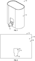
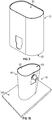
- bag-in-box packaging of the present disclosure is shown generally at 10.
- the bag-in-box packaging of the present disclosure is typically well suited for use in association with any number of different industries and for carrying any number of different flowable materials.
- the packaging is particularly well suited for use in association with the wine industry, for what is known as bag-in-box wine.
- the packaging is not limited for use in association with any particular type of industry or any particular flowable material.
- Bag-in-box packaging 10 includes an outer box 12 enclosing an inner bag 14 (see FIG. 8 ) paired with a dispensing tap 16.
- the outer box 12 has a generally oblong cylindrical configuration. However other shapes may be used, including but not limited to circular cross-sectional shapes, polygon cross-sectional shapes, square cross-sectional shapes and rectangular cross-sectional shapes.
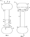
- the outer box 12 can be formed from three pieces of blank material that each preferably comprise a corrugated paperboard material: a side wall blank 18 ( FIG. 2 ), a dispenser-side insert blank 20 ( FIG. 3 ), and a rear-side insert blank 22 ( FIG. 4 ).
- a decorative and/or informational outer layer of printed material may be presented on the outer surface of outer box 12.
- Inner bag 14 may comprise a conventional collapsible prepackaged and vacuum-sealed plastic bag containing a flowable material such as, for example, wine.
- Dispensing tap 16 is disposed at one side of a lower end of inner bag 14 for dispensing the bag's contents. Any number of different configurations are contemplated for the dispensing tap, and the disclosure is not limited to any particular dispensing tap configuration, or any particular dispensing tap.
- One embodiment of a dispensing tap 16 is shown in FIG. 5 .
- dispensing tap 16 includes a neck portion 24 with a rear flange 26 which is sealed to the inner bag 14, an intermediate flange 28 spaced forwardly therefrom, and a radial front flange 30 spaced forwardly from the intermediate flange 28.
- the dispensing tap 16 includes a forward-most dispensing portion 32 that includes a dispensing opening 34.
- Dispensing portion 32 is preferably rotatable so as to enable a user to change the orientation of dispensing opening 34.
- Dispensing portion 32 also includes an actuator 36 that can be actuated to dispense the contents of inner bag 14 out through dispensing opening 34.
- side wall blank 18 is generally rectangular in shape and preferably comprises a single faced corrugated board.
- Side wall blank 18 has a flat linerboard side 38 that forms an exterior surface of the outer box side wall and a fluted side 40 (see FIG. 6 ) that forms an interior surface of the outer box side wall.
- Side wall blank 18 includes a tap access aperture 41 that has a generally "keyhole"-shaped configuration in the illustrated embodiment.
- Aperture 41 includes a generally circular lower portion 42 adjacent to and abutting a generally rectangular upper portion 44.
- dispenser-side insert blank 20 includes a generally rectangular front panel 46.
- Front panel 46 is hingedly connected along its upper edge to a first top flap 48 via tear line 50.
- Front panel 46 is hingedly connected along its lower edge to a first bottom flap 52 via fold line 54.
- First top flap 48 and first bottom flap 52 generally mirror one another and have a generally elliptical or oblong shape in the illustrated embodiment.
- First top flap 48 and first bottom flap 52 each have a substantially oblong shape in the illustrated embodiment, although other shapes may be used.
- First top flap 48 includes a notch 56 struck from its outermost free edge.
- An elongated aperture 58 is disposed along a central length of, and interrupts, fold line 54.
- aperture 58 is struck in part from first bottom flap 52 and in part from front panel 46.
- a tap access feature 60 is disposed on a lower portion of front panel 52.
- Tap access feature 60 has a generally keyhole-shaped configuration that may be identical or substantially similar to the shape of tap access aperture 41.
- Tap access feature 60 comprises a removable lower tab 72 that is generally circular in shape and defined by tear line 62.
- Lower tab 72 is adjacent to and abuts upper tab 70.
- Upper tab 70 is generally rectangular in shape and is defined by side tear lines 64 and 66 and a generally horizontal fold line 68.
- rear-side insert blank 22 generally mirrors dispenser-side insert blank 20.
- Rear-side insert blank 22 includes a generally rectangular rear panel 74.
- Rear panel 74 is hingedly connected along its upper edge to a second top flap 76 via tear line 78.
- Rear panel 74 is hingedly connected along its lower edge to a second bottom flap 80 via fold line 82.
- Second top flap 76 and second bottom flap 80 generally mirror one another and have a generally elliptical or oblong shape in the illustrated embodiment.
- Second top flap 76 and second bottom flap 80 each have a substantially oblong shape in the illustrated embodiment, although other shapes may be used.
- Second bottom flap 80 includes a tab 84 that projects from its outermost free edge.
- Second top flap 76 includes generally rectangular-shaped notches 86 and 88 that are struck from opposite side edges of front panel 74 along tear line 78. Thus, notches 86, 88 also extend partially into second top flap 76.
- a fold line 96 extends across the length of second top flap 76 between opposite side edges.
- Fold line 90 is preferably formed from a series of partial-depth cuts made on the interior surface of second top flap 76. Fold line 90 divides second top flap 76 into a smaller inner portion 91 and a larger outer portion 93.
- FIG. 1 One method of constructing the bag-in-box packaging 10 as illustrated in FIG. 1 will now be described.
- the forming process is not limited to that described below and may be altered according to particular manufacturing requirements.
- side wall blank 18 can be positioned with its interior surface / fluted side 40 face up.
- Glue or other adhesive treatment can be applied to the exterior surface of front panel 46 or, alternatively, to a corresponding portion of the interior surface of side wall blank 18.
- the exterior surface of front panel 46 is then positioned over the interior surface of side wall blank 18 so as to align tap access aperture 41 with tap access feature 60.
- the exterior surface of front panel 48 is brought into face-contacting relationship with the interior surface of side wall blank 18 and secured thereto.
- Glue or other adhesive treatment can be applied to the exterior surface of rear panel 74 or, alternatively, to a corresponding portion of the interior surface of side wall blank 18.
- Rear panel 74 is positioned in partially-overlapping alignment with a first outermost side edge portion 95 of side wall blank 18. An overlapping portion of the exterior surface of rear panel 74 is brought into face-contacting relationship with the interior surface of side wall blank 18 and secured thereto. Side wall blank 18 is then wrapped around so as to bring second outermost side edge portion 97 into face-contacting relationship with the exposed portion of rear panel's 74 exterior surface, securing the two together and forming a generally tubular enclosure.
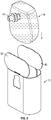
- First top flap 48 is folded inwardly about tear line 50 until it is substantially perpendicular to front panel 46. This positions reduced thickness portion 81 of rear-side insert blank 22 (i.e., the portion defined between notches 86 and 88) within notch 56 of dispenser-side insert blank 20. Projecting portions 83 and 85 adjacent to and defined by notch 56 catch on shoulders 87 and 89 of rear-side insert blank 22, thereby arresting further downward folding of first top flap 48. Glue or other adhesive treatment is applied to outer portion 93 of the interior surface of second top flap 76 or, alternatively, to a corresponding portion of the outer surface of first top flap 48.
- Second top flap 76 is then folded inwardly about tear line 78, thereby bringing its inner surface into face-contacting relationship with the outer surface of first top flap 48 and securing it thereto.
- inner portion 91 of second top flap 76 is not adhered to first top flap 48. This results in the formation of the partially-constructed outer box 12 as shown in FIG. 7 .
- First and second top flaps 48, 76 together form composite top wall 51 of outer box 12.
- Side wall blank 18 together with front and rear panels 46, 74 form a side wall 53 of outer box 12.
- filled inner bag 14 may be inserted into the interior of the outer box 12 through its open bottom end.
- Inner bag 14 is oriented so that tap 16 will be generally adjacent to tap access feature 60.
- Second bottom wall panel 80 is folded inwardly about fold line 82 until it is substantially perpendicular to rear panel 74.
- Tab 84 of rear-side insert blank 22 is received within aperture 58, thereby arresting further downward folding of second bottom flap 80.
- Glue or other adhesive treatment is applied to the outer surface of second bottom flap 80 or, alternatively, to the inner surface of first bottom flap 52.
- First bottom flap 52 is then folded inwardly about fold line 54, thereby brining its inner surface into face-contacting relationship with the outer surface of second bottom flap 80 and securing it thereto.
- First and second bottom flaps 52, 80 together form composite bottom wall 53 of the outer box 12. This completes formation of bag-in-box packaging 10 as shown in FIG. 9 .
- the bag-in-box packaging can be used in its upright configuration (as shown in FIG. 1 ) without requiring the use of a pressure-assisted dispensing advice.
- a user uses a finger or tool to puncture the outer box 12 along tear lines 62, 66, 64.
- Lower tab 72 may be completely removed from outer box 12 and discarded.
- Upper tab 70 may be folded back out of the way along fold line 68, allowing a user to reach into the interior of the box through the opening created by removal of lower tab 72 and the displacement of upper tab 70. The user grasps tab 16 and directs it out of the box through the opening.
- the tap can then be coupled to the box by positioning the tap within the circular portion of the opening so that an adjacent edge of outer box 12 is received within the slot defined between flanges 28 and 30.
- upper tab 70 may be folded back into place so that its lower free edge is received within an upper portion of the slot defined between flanges 28 and 30.
- the tap 16 can then be actuated via actuator 36 to dispense product.
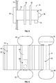
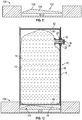
- the bag-in-box packaging 10 is also suitable for use in an inverted configuration when used with a pressure-assisted dispensing device 100.
- Pressure-assisted dispensing device 100 includes an aperture 102 configured to receive the top end of the bag-in-box packaging 10.
- a piston plate 104 is reciprocally disposed within the interior of aperture 102.
- Piston plate 104 preferably has an asymmetric triangular cross-sectional shape as shown in FIG. 10 . Piston plate 104 thus defines an off-center, upwardly-projecting ridge or crest 106.
- the bag-in-box packaging 10 can be inserted top-down into the aperture 102, bringing top wall 51 into contact with piston plate 104.
- Crest 106 is configured to be aligned with fold line 90 of second top flap 76.
- crest 106 is brought into contact with the portion of the outer surface of second top flap 76 that is opposite fold line 90.
- a top closure element (not shown) of pressure-assisted dispensing device may be used to hold outer box 12 in place within aperture 102. The user presses down firmly on the bag-in-box packaging 10, causing the top wall 51 to be severed from side wall 55 along tear lines 50, 78 and driven upwards into the interior of the outer box 12.
- Fold line 90 and the angled nature of piston plate 104 facilitate a controlled creasing of second top flap 76 along fold line 90, thereby facilitating the sliding of top wall 51 within the interior of the outer box 12.
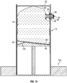
- Pressure-assisted dispensing device 100 is configured to drive piston plate 104 upwards so as to maintain a relatively constant amount of pressure on bag 14, thereby enabling the bag's contents to be dispensed from tap 16 upon its actuation.
- piston plate 104 extends further upwards into the interior of the outer box 12 (as shown in FIG. 13 ).
- piston plate 104 and the controlled creasing of second top flap 76 along fold line 90 facilitates an angling of the top wall's inner surface that advantageously tends to direct fluid towards the dispensing side of the bag-in-box packaging 10, and thus towards tap 16, as the bag 14 is emptied.
- a dispensing tap with a rotatable dispensing portion 32 may be particularly desirable to facilitate the use of the bag-in-box packaging 10 in either an upright or inverted configuration.
- it may be particularly desirable to make use of upper tab 70 to lock tap 16 in place.
- pressure-assisted dispensing device may include a feature configured to hold the tap 16 in place during use.
Landscapes
- Engineering & Computer Science (AREA)
- Mechanical Engineering (AREA)
- Cartons (AREA)
- Packages (AREA)
Claims (15)
- Caisse-outre (10) comprenant :une boîte extérieure (12) ;une poche intérieure souple (14) placée dans une partie intérieure de ladite boîte extérieure ;un robinet distributeur (16) couplé à ladite poche intérieure (14) ;dans laquelle la boîte extérieure (12) comprend une paroi latérale (18, 46, 74), un élément d'accès au robinet (60) formé dans ladite paroi latérale, et une paroi supérieure amovible (51), dans laquelle ladite paroi supérieure comprend des premier et deuxième rabats supérieurs se chevauchant (48, 76), dans laquelle ledit premier rabat supérieur (48) est connecté de manière articulée à un côté avant de ladite paroi latérale (18, 46, 74) le long d'une première ligne de déchirement (50), dans laquelle ledit deuxième rabat supérieur (76) est connecté de manière articulée à un côté arrière de ladite paroi latérale (18, 46, 74) le long d'une deuxième ligne de déchirement (78), dans laquelle ledit côté arrière de ladite paroi latérale (18, 46, 74) est placé à l'opposé dudit côté avant, dans laquelle ladite paroi supérieure (51) est séparable de ladite paroi latérale le long desdites première et deuxième lignes de déchirement.
- Caisse-outre (10) selon la revendication 1, dans laquelle ladite paroi latérale comprend un panneau avant (46), un panneau arrière (74) placé à l'opposé dudit panneau avant, et une découpe de paroi latérale (18) enveloppée autour desdits panneaux avant et arrière (46, 76), dans laquelle ledit premier rabat supérieur (48) est connecté de manière articulée audit panneau avant (46) le long de ladite première ligne de déchirement (50), dans laquelle ledit deuxième rabat supérieur (76) est connecté de manière articulée audit panneau arrière (74) le long de ladite deuxième ligne de déchirement (78).
- Caisse-outre (10) selon la revendication 2, dans laquelle lesdits panneaux avant et arrière sont de forme globalement rectangulaire, et/ou dans laquelle ladite boîte extérieure est de forme cylindrique globalement oblongue.
- Caisse-outre (10) selon la revendication 2, dans laquelle ladite découpe de paroi latérale (18) comprend une ouverture d'accès au robinet (41) disposée par dessus ledit élément d'accès au robinet (60), et/ou dans laquelle ladite découpe de paroi latérale (18) comprend un matériau ondulé à simple face.
- Caisse-outre (10) selon la revendication 1, dans laquelle ledit deuxième rabat supérieur (76) comprend une ligne de pliage (90) qui s'étend entre des bords latéraux opposés dudit deuxième rabat supérieur et qui divise ledit rabat supérieur en une partie intérieure (91) et une partie extérieure (93), ladite partie extérieure (93) ayant une surface plus grande que ladite partie intérieure (91).
- Caisse-outre (10) selon la revendication 5, dans laquelle ladite ligne de pliage (90) comprend une ou plusieurs entaille(s) de profondeur partielle formée(s) sur une surface intérieure dudit deuxième rabat supérieur.
- Caisse-outre (10) selon la revendication 5 ou 6, dans laquelle une surface intérieure de ladite partie extérieure (93) est connectée de manière adhésive audit premier rabat supérieur (48), et dans laquelle ladite partie intérieure (91) dudit deuxième rabat supérieur (76) n'est pas connectée de manière adhésive audit premier rabat supérieur (48).
- Caisse-outre (10) selon l'une quelconque des revendications précédentes, dans laquelle ladite boîte extérieure comprend une paroi inférieure (53), dans laquelle ladite paroi inférieure (53) comprend des premier et deuxième rabats inférieurs se chevauchant (52, 80), dans laquelle ledit premier rabat inférieur (52) est connecté de manière articulée audit côté avant de ladite paroi latérale (18, 46, 74), et dans laquelle ledit deuxième rabat inférieur (80) est connecté de manière articulée audit côté arrière de ladite paroi latérale (18, 46, 74).
- Caisse-outre (10) selon l'une quelconque des revendications précédentes, dans laquelle ledit élément d'accès au robinet (60) comprend au moins une patte amovible (72, 70).
- Caisse-outre (10) selon l'une quelconque des revendications précédentes, dans laquelle ladite caisse-outre (10) est configurée pour être utilisée avec un dispositif de distribution à pression.
- Ensemble de découpes (18, 20, 22) configuré pour former une boîte extérieure (12) destinée à être utilisée avec une caisse-outre (10), l'ensemble de découpes (18, 20, 22) comprenant :une découpe de paroi latérale (18) ;une découpe d'insert côté distributeur (20) comprenant un panneau avant (46) comportant un élément d'accès au robinet (60), un premier rabat supérieur (48) connecté de manière articulée à une extrémité supérieure dudit panneau avant le long d'une première ligne de déchirement (50), et un premier rabat inférieur (52) connecté de manière articulée à une extrémité inférieure dudit panneau avant (46) ; etune découpe d'insert de côté arrière (22) comprenant un panneau arrière (74), un deuxième rabat supérieur (76) connecté de manière articulée à une extrémité supérieure dudit panneau arrière le long d'une deuxième ligne de déchirement (78), et un deuxième rabat inférieur (80) connecté de manière articulée à une extrémité inférieure dudit panneau arrière ;dans lequel, dans une boîte extérieure (12) mise en forme, lesdits premier et deuxième rabats supérieurs (48, 76) se chevauchent pour former une paroi supérieure (51) de ladite boîte extérieure mise en forme (12), lesdits premier et deuxième rabats inférieurs (52, 80) se chevauchent pour former une paroi inférieure (53) de ladite boîte extérieure mise en forme (12), lesdits panneaux avant et arrière (46, 74) sont disposés à l'opposé l'un de l'autre, et ladite découpe de paroi latérale (18) s'enveloppe autour desdits panneaux avant et arrière pour former une paroi latérale de ladite boîte extérieure (12) ;dans lequel, dans ladite boîte extérieure mise en forme, ladite paroi supérieure est séparable de ladite paroi latérale le long desdites première et deuxième lignes de déchirement (50, 78).
- Ensemble de découpes selon la revendication 11, dans lequel ladite découpe de paroi latérale (18) est de forme globalement rectangulaire, et/ou dans lequel lesdits panneaux avant et arrière (46, 74) sont de forme globalement rectangulaire.
- Ensemble de découpes selon la revendication 11, dans lequel ladite boîte extérieure mise en forme est de forme cylindrique globalement oblongue, et/ou dans lequel ladite découpe de paroi latérale (18) comprend une ouverture d'accès au robinet (41) configurée pour être disposée par-dessus ledit élément d'accès au robinet (60) dans ladite boîte extérieure mise en forme.
- Ensemble de découpes selon la revendication 11, dans lequel ladite découpe de paroi latérale (18) comprend un matériau ondulé à simple face.
- Ensemble de découpes selon la revendication 11, dans lequel ledit deuxième rabat supérieur (76) comprend une ligne de pliage (90) qui s'étend entre des bords latéraux opposés dudit deuxième rabat supérieur et qui divise ledit rabat supérieur en une partie intérieure (91) et une partie extérieure (93), ladite partie extérieure (93) ayant une surface plus grande que ladite partie intérieure (91), et dans lequel ladite ligne de pliage (90) comprend une ou plusieurs entaille(s) de profondeur partielle formée(s) sur une surface intérieure dudit deuxième rabat supérieur (76).
Applications Claiming Priority (2)
| Application Number | Priority Date | Filing Date | Title |
|---|---|---|---|
| US201662434725P | 2016-12-15 | 2016-12-15 | |
| PCT/US2017/065749 WO2018111836A1 (fr) | 2016-12-15 | 2017-12-12 | Emballage de sac en boîte |
Publications (3)
| Publication Number | Publication Date |
|---|---|
| EP3554964A1 EP3554964A1 (fr) | 2019-10-23 |
| EP3554964A4 EP3554964A4 (fr) | 2020-06-17 |
| EP3554964B1 true EP3554964B1 (fr) | 2021-10-20 |
Family
ID=62559208
Family Applications (1)
| Application Number | Title | Priority Date | Filing Date |
|---|---|---|---|
| EP17881270.7A Active EP3554964B1 (fr) | 2016-12-15 | 2017-12-12 | Emballage de sac en boîte et ensemble de découpes |
Country Status (6)
| Country | Link |
|---|---|
| US (2) | US10981711B2 (fr) |
| EP (1) | EP3554964B1 (fr) |
| CA (1) | CA3046657A1 (fr) |
| ES (1) | ES2906082T3 (fr) |
| MX (1) | MX2019007001A (fr) |
| WO (1) | WO2018111836A1 (fr) |
Families Citing this family (2)
| Publication number | Priority date | Publication date | Assignee | Title |
|---|---|---|---|---|
| WO2021161082A1 (fr) | 2020-02-14 | 2021-08-19 | Georgia-Pacific Corrugated Llc | Ensembles boîtes en carton ondulé en plusieurs parties, décpoupes et systèmes pour des produits distribués en caisse-outre lourds |
| USD980069S1 (en) | 2020-07-14 | 2023-03-07 | Ball Corporation | Metallic dispensing lid |
Family Cites Families (13)
| Publication number | Priority date | Publication date | Assignee | Title |
|---|---|---|---|---|
| GB836246A (en) | 1957-01-11 | 1960-06-01 | Mauser Rudolf | A packing and transport container for liquids |
| US5803346A (en) * | 1996-05-15 | 1998-09-08 | Longview Fibre Company | Paperboard container for liquids including an improved structure to prevent fitment rotation |
| NL1012113C2 (nl) | 1999-05-20 | 2000-11-21 | Kappa Trimbach B V | Verpakking, voorzien van een reeks subverpakkingen. |
| US20030132275A1 (en) * | 2002-01-16 | 2003-07-17 | Ingalls Samuel L. | Multi-ply corrugated containers, such as bulk bins, and fitment retainers, such as drain fitment retainers usable with bulk bins |
| US7007825B2 (en) * | 2002-11-13 | 2006-03-07 | Smurfit-Stone Container Enterprises, Inc. | Bag-in-box beverage container |
| GB0314815D0 (en) * | 2003-06-25 | 2003-07-30 | Stephenson John | Bag in box |
| WO2007084525A2 (fr) * | 2006-01-17 | 2007-07-26 | Graphic Packaging International, Inc. | Carton dote d’une fermeture pour sac |
| US7984845B2 (en) * | 2008-05-19 | 2011-07-26 | Millercoors, Llc | Regulated fluid dispensing system packaging |
| EP2396231A1 (fr) * | 2008-10-13 | 2011-12-21 | Ables Care V/Erik Stenderup | Distributeur pour distribuer des fluides stockés dans des emballages compressibles |
| MX2011004203A (es) * | 2008-10-23 | 2011-09-27 | Dow Agrosciences Llc | Recipiente plegable para mantener un producto vertible. |
| US8276806B2 (en) * | 2008-11-21 | 2012-10-02 | Graphic Packaging International, Inc. | Carton for flowable material |
| US8720769B2 (en) | 2009-09-15 | 2014-05-13 | Packaging Corporation Of America | Beverage container |
| US8844797B2 (en) * | 2009-11-11 | 2014-09-30 | Rock-Tenn Shared Services, Llc | Liquid dispensing containers and blanks for making the same |
-
2017
- 2017-12-12 CA CA3046657A patent/CA3046657A1/fr active Pending
- 2017-12-12 US US16/347,404 patent/US10981711B2/en active Active
- 2017-12-12 EP EP17881270.7A patent/EP3554964B1/fr active Active
- 2017-12-12 ES ES17881270T patent/ES2906082T3/es active Active
- 2017-12-12 WO PCT/US2017/065749 patent/WO2018111836A1/fr unknown
- 2017-12-12 MX MX2019007001A patent/MX2019007001A/es unknown
-
2021
- 2021-03-26 US US17/214,224 patent/US20210214141A1/en not_active Abandoned
Also Published As
| Publication number | Publication date |
|---|---|
| EP3554964A4 (fr) | 2020-06-17 |
| US10981711B2 (en) | 2021-04-20 |
| ES2906082T3 (es) | 2022-04-13 |
| US20210214141A1 (en) | 2021-07-15 |
| WO2018111836A1 (fr) | 2018-06-21 |
| EP3554964A1 (fr) | 2019-10-23 |
| CA3046657A1 (fr) | 2018-06-21 |
| MX2019007001A (es) | 2019-09-05 |
| US20190256271A1 (en) | 2019-08-22 |
Similar Documents
| Publication | Publication Date | Title |
|---|---|---|
| US8276806B2 (en) | Carton for flowable material | |
| AU2006330898B2 (en) | Carton with handle | |
| AU2006275412B2 (en) | Cartons with dispensing features | |
| US2321139A (en) | Collapsible paper container | |
| EP3423364B1 (fr) | Carton doté d'éléments de déploiement, ébauche et méthode pour former ce carton | |
| JP2008531425A (ja) | バッグインボックス | |
| US20210214141A1 (en) | Bag-in-Box Packaging | |
| WO2010011627A1 (fr) | Contenant-cube en carton | |
| AU2007248577B2 (en) | Carton with vent openings, blank and folding method | |
| US10968007B2 (en) | Bag in box container and box therefor | |
| AU2006326519B2 (en) | Carton having a pivotable dispenser | |
| AU2016298258C1 (en) | Modular carton | |
| CA2572778C (fr) | Boite pour caisse-outre avec acces permettant de determiner l'emplacement du bec verseur | |
| JP2022552688A (ja) | カップ、カップ用ブランク、及びカップを形成する方法 | |
| JP2016525045A (ja) | カートン及びカートンブランク | |
| US7971773B2 (en) | Carton with spout | |
| EP2035286B1 (fr) | Carton doté d'un element de versement | |
| US7581673B2 (en) | Container with reclosable pour spout | |
| JPH06345082A (ja) | 包装容器を形成するための方法ならびにブランク、およびそれにより形成された包装容器 |
Legal Events
| Date | Code | Title | Description |
|---|---|---|---|
| STAA | Information on the status of an ep patent application or granted ep patent |
Free format text: STATUS: THE INTERNATIONAL PUBLICATION HAS BEEN MADE |
|
| PUAI | Public reference made under article 153(3) epc to a published international application that has entered the european phase |
Free format text: ORIGINAL CODE: 0009012 |
|
| STAA | Information on the status of an ep patent application or granted ep patent |
Free format text: STATUS: REQUEST FOR EXAMINATION WAS MADE |
|
| 17P | Request for examination filed |
Effective date: 20190625 |
|
| AK | Designated contracting states |
Kind code of ref document: A1 Designated state(s): AL AT BE BG CH CY CZ DE DK EE ES FI FR GB GR HR HU IE IS IT LI LT LU LV MC MK MT NL NO PL PT RO RS SE SI SK SM TR |
|
| AX | Request for extension of the european patent |
Extension state: BA ME |
|
| DAV | Request for validation of the european patent (deleted) | ||
| DAX | Request for extension of the european patent (deleted) | ||
| A4 | Supplementary search report drawn up and despatched |
Effective date: 20200519 |
|
| RIC1 | Information provided on ipc code assigned before grant |
Ipc: B67D 1/04 20060101ALI20200513BHEP Ipc: B65D 77/06 20060101AFI20200513BHEP Ipc: B65D 5/32 20060101ALN20200513BHEP |
|
| GRAP | Despatch of communication of intention to grant a patent |
Free format text: ORIGINAL CODE: EPIDOSNIGR1 |
|
| STAA | Information on the status of an ep patent application or granted ep patent |
Free format text: STATUS: GRANT OF PATENT IS INTENDED |
|
| RIC1 | Information provided on ipc code assigned before grant |
Ipc: B65D 5/32 20060101ALN20210406BHEP Ipc: B67D 1/04 20060101ALI20210406BHEP Ipc: B65D 77/06 20060101AFI20210406BHEP |
|
| INTG | Intention to grant announced |
Effective date: 20210504 |
|
| GRAS | Grant fee paid |
Free format text: ORIGINAL CODE: EPIDOSNIGR3 |
|
| GRAA | (expected) grant |
Free format text: ORIGINAL CODE: 0009210 |
|
| STAA | Information on the status of an ep patent application or granted ep patent |
Free format text: STATUS: THE PATENT HAS BEEN GRANTED |
|
| AK | Designated contracting states |
Kind code of ref document: B1 Designated state(s): AL AT BE BG CH CY CZ DE DK EE ES FI FR GB GR HR HU IE IS IT LI LT LU LV MC MK MT NL NO PL PT RO RS SE SI SK SM TR |
|
| REG | Reference to a national code |
Ref country code: GB Ref legal event code: FG4D |
|
| REG | Reference to a national code |
Ref country code: CH Ref legal event code: EP |
|
| REG | Reference to a national code |
Ref country code: DE Ref legal event code: R096 Ref document number: 602017048077 Country of ref document: DE |
|
| REG | Reference to a national code |
Ref country code: IE Ref legal event code: FG4D |
|
| REG | Reference to a national code |
Ref country code: AT Ref legal event code: REF Ref document number: 1439772 Country of ref document: AT Kind code of ref document: T Effective date: 20211115 |
|
| REG | Reference to a national code |
Ref country code: LT Ref legal event code: MG9D |
|
| REG | Reference to a national code |
Ref country code: NL Ref legal event code: MP Effective date: 20211020 |
|
| REG | Reference to a national code |
Ref country code: AT Ref legal event code: MK05 Ref document number: 1439772 Country of ref document: AT Kind code of ref document: T Effective date: 20211020 |
|
| REG | Reference to a national code |
Ref country code: ES Ref legal event code: FG2A Ref document number: 2906082 Country of ref document: ES Kind code of ref document: T3 Effective date: 20220413 |
|
| PG25 | Lapsed in a contracting state [announced via postgrant information from national office to epo] |
Ref country code: RS Free format text: LAPSE BECAUSE OF FAILURE TO SUBMIT A TRANSLATION OF THE DESCRIPTION OR TO PAY THE FEE WITHIN THE PRESCRIBED TIME-LIMIT Effective date: 20211020 Ref country code: LT Free format text: LAPSE BECAUSE OF FAILURE TO SUBMIT A TRANSLATION OF THE DESCRIPTION OR TO PAY THE FEE WITHIN THE PRESCRIBED TIME-LIMIT Effective date: 20211020 Ref country code: FI Free format text: LAPSE BECAUSE OF FAILURE TO SUBMIT A TRANSLATION OF THE DESCRIPTION OR TO PAY THE FEE WITHIN THE PRESCRIBED TIME-LIMIT Effective date: 20211020 Ref country code: BG Free format text: LAPSE BECAUSE OF FAILURE TO SUBMIT A TRANSLATION OF THE DESCRIPTION OR TO PAY THE FEE WITHIN THE PRESCRIBED TIME-LIMIT Effective date: 20220120 Ref country code: AT Free format text: LAPSE BECAUSE OF FAILURE TO SUBMIT A TRANSLATION OF THE DESCRIPTION OR TO PAY THE FEE WITHIN THE PRESCRIBED TIME-LIMIT Effective date: 20211020 |
|
| PG25 | Lapsed in a contracting state [announced via postgrant information from national office to epo] |
Ref country code: IS Free format text: LAPSE BECAUSE OF FAILURE TO SUBMIT A TRANSLATION OF THE DESCRIPTION OR TO PAY THE FEE WITHIN THE PRESCRIBED TIME-LIMIT Effective date: 20220220 Ref country code: SE Free format text: LAPSE BECAUSE OF FAILURE TO SUBMIT A TRANSLATION OF THE DESCRIPTION OR TO PAY THE FEE WITHIN THE PRESCRIBED TIME-LIMIT Effective date: 20211020 Ref country code: PT Free format text: LAPSE BECAUSE OF FAILURE TO SUBMIT A TRANSLATION OF THE DESCRIPTION OR TO PAY THE FEE WITHIN THE PRESCRIBED TIME-LIMIT Effective date: 20220221 Ref country code: PL Free format text: LAPSE BECAUSE OF FAILURE TO SUBMIT A TRANSLATION OF THE DESCRIPTION OR TO PAY THE FEE WITHIN THE PRESCRIBED TIME-LIMIT Effective date: 20211020 Ref country code: NO Free format text: LAPSE BECAUSE OF FAILURE TO SUBMIT A TRANSLATION OF THE DESCRIPTION OR TO PAY THE FEE WITHIN THE PRESCRIBED TIME-LIMIT Effective date: 20220120 Ref country code: NL Free format text: LAPSE BECAUSE OF FAILURE TO SUBMIT A TRANSLATION OF THE DESCRIPTION OR TO PAY THE FEE WITHIN THE PRESCRIBED TIME-LIMIT Effective date: 20211020 Ref country code: LV Free format text: LAPSE BECAUSE OF FAILURE TO SUBMIT A TRANSLATION OF THE DESCRIPTION OR TO PAY THE FEE WITHIN THE PRESCRIBED TIME-LIMIT Effective date: 20211020 Ref country code: HR Free format text: LAPSE BECAUSE OF FAILURE TO SUBMIT A TRANSLATION OF THE DESCRIPTION OR TO PAY THE FEE WITHIN THE PRESCRIBED TIME-LIMIT Effective date: 20211020 Ref country code: GR Free format text: LAPSE BECAUSE OF FAILURE TO SUBMIT A TRANSLATION OF THE DESCRIPTION OR TO PAY THE FEE WITHIN THE PRESCRIBED TIME-LIMIT Effective date: 20220121 |
|
| REG | Reference to a national code |
Ref country code: DE Ref legal event code: R119 Ref document number: 602017048077 Country of ref document: DE |
|
| PG25 | Lapsed in a contracting state [announced via postgrant information from national office to epo] |
Ref country code: SM Free format text: LAPSE BECAUSE OF FAILURE TO SUBMIT A TRANSLATION OF THE DESCRIPTION OR TO PAY THE FEE WITHIN THE PRESCRIBED TIME-LIMIT Effective date: 20211020 Ref country code: SK Free format text: LAPSE BECAUSE OF FAILURE TO SUBMIT A TRANSLATION OF THE DESCRIPTION OR TO PAY THE FEE WITHIN THE PRESCRIBED TIME-LIMIT Effective date: 20211020 Ref country code: RO Free format text: LAPSE BECAUSE OF FAILURE TO SUBMIT A TRANSLATION OF THE DESCRIPTION OR TO PAY THE FEE WITHIN THE PRESCRIBED TIME-LIMIT Effective date: 20211020 Ref country code: MC Free format text: LAPSE BECAUSE OF FAILURE TO SUBMIT A TRANSLATION OF THE DESCRIPTION OR TO PAY THE FEE WITHIN THE PRESCRIBED TIME-LIMIT Effective date: 20211020 Ref country code: EE Free format text: LAPSE BECAUSE OF FAILURE TO SUBMIT A TRANSLATION OF THE DESCRIPTION OR TO PAY THE FEE WITHIN THE PRESCRIBED TIME-LIMIT Effective date: 20211020 Ref country code: DK Free format text: LAPSE BECAUSE OF FAILURE TO SUBMIT A TRANSLATION OF THE DESCRIPTION OR TO PAY THE FEE WITHIN THE PRESCRIBED TIME-LIMIT Effective date: 20211020 Ref country code: CZ Free format text: LAPSE BECAUSE OF FAILURE TO SUBMIT A TRANSLATION OF THE DESCRIPTION OR TO PAY THE FEE WITHIN THE PRESCRIBED TIME-LIMIT Effective date: 20211020 |
|
| REG | Reference to a national code |
Ref country code: CH Ref legal event code: PL |
|
| PLBE | No opposition filed within time limit |
Free format text: ORIGINAL CODE: 0009261 |
|
| STAA | Information on the status of an ep patent application or granted ep patent |
Free format text: STATUS: NO OPPOSITION FILED WITHIN TIME LIMIT |
|
| REG | Reference to a national code |
Ref country code: BE Ref legal event code: MM Effective date: 20211231 |
|
| 26N | No opposition filed |
Effective date: 20220721 |
|
| PG25 | Lapsed in a contracting state [announced via postgrant information from national office to epo] |
Ref country code: LU Free format text: LAPSE BECAUSE OF NON-PAYMENT OF DUE FEES Effective date: 20211212 Ref country code: IE Free format text: LAPSE BECAUSE OF NON-PAYMENT OF DUE FEES Effective date: 20211212 Ref country code: DE Free format text: LAPSE BECAUSE OF NON-PAYMENT OF DUE FEES Effective date: 20220701 Ref country code: AL Free format text: LAPSE BECAUSE OF FAILURE TO SUBMIT A TRANSLATION OF THE DESCRIPTION OR TO PAY THE FEE WITHIN THE PRESCRIBED TIME-LIMIT Effective date: 20211020 |
|
| PG25 | Lapsed in a contracting state [announced via postgrant information from national office to epo] |
Ref country code: SI Free format text: LAPSE BECAUSE OF FAILURE TO SUBMIT A TRANSLATION OF THE DESCRIPTION OR TO PAY THE FEE WITHIN THE PRESCRIBED TIME-LIMIT Effective date: 20211020 Ref country code: BE Free format text: LAPSE BECAUSE OF NON-PAYMENT OF DUE FEES Effective date: 20211231 |
|
| PG25 | Lapsed in a contracting state [announced via postgrant information from national office to epo] |
Ref country code: LI Free format text: LAPSE BECAUSE OF NON-PAYMENT OF DUE FEES Effective date: 20211231 Ref country code: CH Free format text: LAPSE BECAUSE OF NON-PAYMENT OF DUE FEES Effective date: 20211231 |
|
| PG25 | Lapsed in a contracting state [announced via postgrant information from national office to epo] |
Ref country code: CY Free format text: LAPSE BECAUSE OF FAILURE TO SUBMIT A TRANSLATION OF THE DESCRIPTION OR TO PAY THE FEE WITHIN THE PRESCRIBED TIME-LIMIT Effective date: 20211020 |
|
| P01 | Opt-out of the competence of the unified patent court (upc) registered |
Effective date: 20230601 |
|
| PG25 | Lapsed in a contracting state [announced via postgrant information from national office to epo] |
Ref country code: HU Free format text: LAPSE BECAUSE OF FAILURE TO SUBMIT A TRANSLATION OF THE DESCRIPTION OR TO PAY THE FEE WITHIN THE PRESCRIBED TIME-LIMIT; INVALID AB INITIO Effective date: 20171212 |
|
| PGFP | Annual fee paid to national office [announced via postgrant information from national office to epo] |
Ref country code: GB Payment date: 20231227 Year of fee payment: 7 |
|
| PGFP | Annual fee paid to national office [announced via postgrant information from national office to epo] |
Ref country code: IT Payment date: 20231220 Year of fee payment: 7 Ref country code: FR Payment date: 20231227 Year of fee payment: 7 |
|
| PGFP | Annual fee paid to national office [announced via postgrant information from national office to epo] |
Ref country code: ES Payment date: 20240102 Year of fee payment: 7 |
|
| PG25 | Lapsed in a contracting state [announced via postgrant information from national office to epo] |
Ref country code: MK Free format text: LAPSE BECAUSE OF FAILURE TO SUBMIT A TRANSLATION OF THE DESCRIPTION OR TO PAY THE FEE WITHIN THE PRESCRIBED TIME-LIMIT Effective date: 20211020 |