EP3554950B1 - Mechanismus zum einsatz eines ausgelösten satelliten - Google Patents
Mechanismus zum einsatz eines ausgelösten satelliten Download PDFInfo
- Publication number
- EP3554950B1 EP3554950B1 EP16924261.7A EP16924261A EP3554950B1 EP 3554950 B1 EP3554950 B1 EP 3554950B1 EP 16924261 A EP16924261 A EP 16924261A EP 3554950 B1 EP3554950 B1 EP 3554950B1
- Authority
- EP
- European Patent Office
- Prior art keywords
- satellite
- retention members
- deployment
- payload
- opposing retention
- Prior art date
- Legal status (The legal status is an assumption and is not a legal conclusion. Google has not performed a legal analysis and makes no representation as to the accuracy of the status listed.)
- Active
Links
Images





Classifications
-
- B—PERFORMING OPERATIONS; TRANSPORTING
- B64—AIRCRAFT; AVIATION; COSMONAUTICS
- B64G—COSMONAUTICS; VEHICLES OR EQUIPMENT THEREFOR
- B64G1/00—Cosmonautic vehicles
- B64G1/10—Artificial satellites; Systems of such satellites; Interplanetary vehicles
-
- B—PERFORMING OPERATIONS; TRANSPORTING
- B64—AIRCRAFT; AVIATION; COSMONAUTICS
- B64G—COSMONAUTICS; VEHICLES OR EQUIPMENT THEREFOR
- B64G1/00—Cosmonautic vehicles
- B64G1/22—Parts of, or equipment specially adapted for fitting in or to, cosmonautic vehicles
- B64G1/64—Systems for coupling or separating cosmonautic vehicles or parts thereof, e.g. docking arrangements
- B64G1/641—Interstage or payload connectors
-
- B—PERFORMING OPERATIONS; TRANSPORTING
- B64—AIRCRAFT; AVIATION; COSMONAUTICS
- B64G—COSMONAUTICS; VEHICLES OR EQUIPMENT THEREFOR
- B64G1/00—Cosmonautic vehicles
- B64G1/22—Parts of, or equipment specially adapted for fitting in or to, cosmonautic vehicles
- B64G1/64—Systems for coupling or separating cosmonautic vehicles or parts thereof, e.g. docking arrangements
- B64G1/641—Interstage or payload connectors
- B64G1/643—Interstage or payload connectors for arranging multiple satellites in a single launcher
-
- B—PERFORMING OPERATIONS; TRANSPORTING
- B64—AIRCRAFT; AVIATION; COSMONAUTICS
- B64G—COSMONAUTICS; VEHICLES OR EQUIPMENT THEREFOR
- B64G1/00—Cosmonautic vehicles
- B64G1/22—Parts of, or equipment specially adapted for fitting in or to, cosmonautic vehicles
- B64G1/64—Systems for coupling or separating cosmonautic vehicles or parts thereof, e.g. docking arrangements
- B64G1/645—Separators
- B64G1/6457—Springs; Shape memory actuators
Definitions
- Satellites and other payloads can be carried by launch systems, such as rocket vehicles, into orbit or other destinations in space. Once the launch system reaches a destination or desired orbit characteristic, then payload satellites, probes, or other payloads can be deployed and placed into a functioning mode. Satellites can be placed into Earth orbit (or into orbit around other bodies), and these satellites can perform various tasks, such as sensing, surveillance, communications, or scientific experimentation.
- Example satellites include CubeSat-based satellites.
- CubeSats are a standardized miniaturized satellite architecture for use in inexpensive and rapidly developed space/orbital platforms. CubeSats can come in 10 ⁇ 10 ⁇ 11.35 centimeter (cm) modular units and multiples thereof. CubeSats allow any number of functions and operations to be deployed into a modular format that includes a standardized chassis to which developers can mount electronics, propulsion systems, sensors, experiments, or other equipment.
- deployment of CubeSats and various other types of satellites and space-faring probes can be challenging due to the environment of space as well as the rigors of launch.
- traditional deployment systems for CubeSats include bulky metallic box enclosures that lead to significant restrictions on size and weight of the associated CubeSats.
- US 2016/311562 A1 discloses a release system for deploying satellites.
- the release system comprises a space vehicle separation plate operably coupled to a space vehicle, a launch vehicle adaptor plate operably coupled to a launch vehicle capable of carrying the space vehicle into space for release of the space vehicle from the launch vehicle, an actuator release mechanism assembly and a biasing element assembly.
- a satellite deployment apparatus is provided in claim 1 and a method of operating a satellite deployment mechanism is provided in claim 10. Embodiments thereof are defined in the dependent claims.
- Payloads can be carried by launch systems from ground-based locations into orbits of various types or for delivery to other space-related destinations.
- the payloads such as satellites, scientific probes, or other objects, can be deployed and then placed into an operational mode.
- a deployment mechanism is employed to deploy the payloads away from a stage of the launch system.
- weight and size are critical considerations in launch systems and deployed payloads, due in part to the high cost of launch.
- failure of complex deployment systems can lead to failure to deploy or loss of payload.
- Provided herein are various improvements to satellite or payload deployment systems and equipment that can be employed in many types of satellite or payload deployment scenarios.
- CubeSats Traditional deployers for small satellites, such as CubeSats, might completely enclose a modular satellite in a metallic box structure, causing significant restrictions on the size and weight of the CubeSats that can be flown.
- the new mechanisms and systems herein allows for CubeSats or other satellites and payloads to be launched without the weight and volume constraints that are present on traditional deployers.
- the enhanced examples herein can also be adapted to different size CubeSats (1U, 1.5U, 2U, 3U, 6U, etc%) while maintaining similar component types and operations across the various size deployers.
- the new deployer examples herein can interface to CubeSats using a pair of opposing 'hooks' that slide over a set of small protruding chassis rails that are standard to CubeSats. These hooks are spring-loaded, and held in relative position by a trigger mechanism that, when released, allows the hooks to slide away from the CubeSat chassis rails.
- a set of compressive spring-loaded pusher plates can be employed to push or accelerate the CubeSat away from the deployment mechanism for deployment.
- the CubeSat chassis includes rails typically comprising solid metal members that interface to a standardized Poly Pico satellite Orbital Deployer (PPOD).
- PPOD Poly Pico satellite Orbital Deployer
- Spring plungers are inserted into the ends of the conventional chassis rails to help facilitate satellite separation once the CubeSats have left the deployer.
- Microswitches can also be included in the chassis rails to indicate a successful deployment to control logic/ telemetry.
- a standardized PPOD is not employed and instead an enhanced deployer is provided.
- spring plungers are no longer needed in the CubeSat chassis rails - saving complexity and weight.
- Figure 1 illustrates two views of payload deployment system 102.
- payload 110 is inserted and stowed into payload deployment system 102.
- First view 100 illustrates payload 110 in a pre-deployment state.
- payload 110 is deployed from payload deployment system 102 into a generally 'z' direction indicted by the movement arrow in Figure 1 .
- payload deployment system 102 includes baseplate 120 and deployment mechanism 130.
- Deployment mechanism 130 includes opposing payload retention members 122, action bars 123, and hammer arm 124, along with further elements detailed below in the subsequent figures.
- Action bars 123, hammer arm 124, hammer element 125 can be included in a hammer mechanism or hammer assembly.
- Payload retention members 122 can slide along linear rails 133 and are generally placed into two relative positions, open and closed. When in the 'closed' relative position, payload retention members 122 engage with protrusions 111 of payload 110 to hold payload 110 with respect to baseplate 120. Payload retention members 122 can slide over linear rails 133, and thus can be considered sliding retention members. At least one pusher element 127 is configured to preload a deployment force on payload 110 against payload retention members 122 when the protrusions of payload 110 are captive in payload retention members 122. The preloading occurs when payload 110 is inserted into payload deployment system 102 to engage protrusions 111 with payload retention members 122.
- Deployment mechanism 130 can spread apart opposing payload retention members 122 to an 'open' relative position responsive to triggering by an actuator system.
- the actuator system (not shown in Figure 1 ) moves hammer arm 124 which is coupled to action bars 123 that move apart payload retention members 122.
- the spreading of payload retention members 122 then releases protrusions 111 of payload 110 from payload retention members 122, allowing the preloaded deployment force to act upon payload 110 and accelerate payload 110 away from baseplate 120 for deployment.
- the elements of payload deployment system 102 can comprise various materials, such as metals, metallic alloys, polymers, plastics, ceramics, or other suitable materials.
- aluminum is employed for baseplate 120 and payload retention members 122, among other elements.
- Titanium can be employed for more wear-prone elements, such as the hammer elements and sear elements discussed below.
- Steel or other materials can be employed for spring elements and bearing elements, although other materials can be employed.
- Various surfaces can employ coatings, anodization, hard anodization, or treatments to reduce corrosion, cold welding, electrical conduction, or other undesired conditions.
- Figure 2 illustrates view 200 that shows a stowed or pre-deployment payload 110 within payload deployment system 102. Some elements are indicated in view 200 for clarity, such as baseplate 120, payload retention members 122, and deployment mechanism 130.
- FIG. 2 A detailed view 201 of payload retention members 122 is shown in Figure 2 . This detailed view shows a "hook” version of payload retention members 122.
- a “roller” version of payload retention members 122 can be seen in Figure 6 .
- protrusions 111 of payload 110 are engaged into a space created in ends of payload retention members 122 by lower hook portion 151 and upper hook portion 152 forming a hook 150.
- protrusions 111 When engaged into the end hook 150 of payload retention members 122, protrusions 111 each are constrained in at least two dimensions, namely the x-y plane indicated in Figure 2 , by opposing faces of the hook portions of payload retention members 122.
- payload 110 is constrained using associated pusher elements 127 in the 'z' axis between a space created by hook portions 151-152.
- Payload retention members 122 can slide via linear rails 133 in the 'x' direction for engaging and disengaging from protrusions 111 of payload 110.
- Payload retention members 122 There can be provided a predetermined amount of clearance between the payload protrusions and hook or roller portions of payload retention members 122 that allows for the protrusions to slide into the hook or roller portions.
- payload retention members 122 are closed by sliding inward towards each other along linear rails 133, the payload is restrained in at least two dimensions against the face and wall of the hook or roller portions.
- Pusher plates such as pusher elements 127, act on a bottom side or rail of the payload, attempting to push the payload away from the baseplate 120.
- the pusher plates force the payload against an upper face 152 of the hook or roller, and the friction between the payload protrusions and hook or roller prevents the payload from moving under vibration events.
- the amount of preload force can be increased by increasing a spring constant or a preload of associated pusher plate springs.
- small adjustment pads may be added to the hooks or rollers to take up a predetermined amount of clearance between the protrusions and the hook or roller portions.
- the adjustment pads can comprise set screws with nylon tips to allow tightening against the payload or protrusions without marring or damaging the payload.
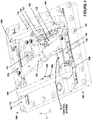
- Figure 3 illustrates an isometric view 300 of payload deployment system 102.
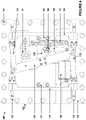
- Figure 4 illustrates a top view 400 of payload deployment system 102.
- Figure 5 illustrates exploded view 500 of payload deployment system 102. Similar elements are included across each of view 300, view 400, and view 500.
- payload deployment system 102 includes baseplate 120, baseplate mounting features 121, payload retention members 122, action arms 123, hammer arm 124, hammer element 125, sear element 126, pusher elements 127, spring elements 131-132, linear rails 133, and actuator system 140.
- Deployment mechanism 130 includes several of these elements, namely payload retention members 122, action arms 123, hammer arm 124, hammer element 125, sear element 126, pusher elements 127, spring elements 131-132, linear rails 133, and actuator system 140.
- Actuator system 140 can be coupled to a control system that might comprise control electronics, control circuitry, activation circuitry, or might include fluid control elements when hydraulic or pneumatic actuators are employed.
- a payload is inserted into deployment mechanism 130 where protrusions on the payload engage into hooks 150 (or rollers) of payload retention members 122.
- a holding force in the 'x' axis is provided by a spring-loaded mechanism that includes sear element 126 coupled to hammer element 125, hammer arm 124, and action arms 123.
- Hammer arm 124 is coupled to hammer element 125, such as by fasteners, welds, or other coupling elements.
- hammer element 125 and hammer arm 124 comprise a single piece or part, forming hammer element 125.
- Hammer element 125 is held against sear element 126 by at least an extension spring.
- Both hammer element 125 and sear element 126 are pivotably coupled to baseplate 120, such as mounted on bearings that can be pressed into baseplate 120.
- Sear element 126 is triggered by linear actuator system 140 that causes sear element 126 to release hammer element 125 and hammer arm 124.
- Hammer arm 124 thus moves when sear element 126 releases hammer element 125 which is coupled to hammer arm 124.
- Hammer element 125 is pivotably coupled to baseplate 120 and spring loaded by 131.
- Hammer arm 124 is pivotably coupled to a pair of action bars 123, which in turn act on payload retention members 122.
- Payload retention members 122 include rail channels 153 that move on linear guide rails 133, which allow motion of payload retention members 122 and allow payload retention members 122 to slide towards and away from protrusions 111 of payload 110.
- Pusher plates such as pusher elements 127
- pusher elements 127 are typically in contact with a bottom portion of payload 110. Once payload retention members 122 are spread apart by actuator system 140, pusher elements 127 exert a force on payload 110 in the 'z' direction away from baseplate 120, and thus deploy payload 110.
- Pusher elements 127 each exert a corresponding force onto the payload based on a spring force established during insertion of the payload into deployment mechanism 130. This spring force keeps the protrusions of the payload engaged in the 'z' axis in hooks 150 of payload retention members 122 until payload retention members 122 are spread apart along linear rails 133 by the triggering of actuator system 140.
- Pusher elements 127 allow payload 110 to be preloaded against hooks 150, establishing an invariant load path and allowing for less vibration to be transferred to payload 110.
- actuator system 140 exerts a force via actuation arm 141 on sear element 126 which is tensioned by spring 132 and rotates on an associated pivot 128.
- actuation arm 141 When a predetermined threshold force is exerted by actuator system 140 onto sear element 126, then sear element 126 will rotate past a 'trigger' feature of sear element 126 and begin to exert a force on hammer element 125 which responsively rotates on an associated pivot 129.
- Actuator system 140 can be controlled by an associated control system, not shown in Figures 3-5 for clarity. This control system can provide power or pressure to an actuator of actuator system to actuate or activate the actuator.
- Actuator system 140 can be triggered remotely, either by ground control systems or by an onboard timer or control system.
- Actuator system 140 can comprise a linear actuator, although variations are possible.
- the linear actuator can be coupled to baseplate 120 and exert a force onto sear element 126 which responsively rotates about pivot 128.
- the type of linear actuator can vary.
- leadscrew actuator can be employed.
- Other example actuators include solenoid actuators, paraffin actuators, ballscrew actuators, and linear motor actuators, among others, including combinations thereof.
- Other example actuators include rotational actuators, such as servos, motors, and the like, that rotate sear element 126 directly or through a gearing mechanism.
- Sear element 126 establishes a locking feature for payload deployment system 102.
- payload retention members 122 When payload retention members 122 are placed into the closed relative position to engage protrusions 111 of payload 110, sear element 126 can lock payload retention members 122 into the closed relative position.
- Spring 132 maintains sear element 126 into the 'locked' position against hammer element 125. This locked or closed relative position can be maintained to hold payload 110 during the rigors of a rocket vehicle launch process or until deployment is desired.
- Deployment of payload 110 can be initiated to separate payload 110 from a launch vehicle or vehicle stage, such as once a microgravity environment is established or a desired orbit is achieved. Movement of action bars 123, hammer arm 124, hammer element 125 can be triggered by sear element 126. Sear element 126 can be rotated by actuator system 140. When sear element 126 is rotated past a predetermined threshold angle of rotation, then sear element 126 'triggers' off hammer element 125 and allows hammer element 125 to pivotably rotate with respect to baseplate 120. Since hammer element 125 is coupled to hammer arm 124, then hammer arm 124 also rotates along with hammer element 125.
- Spring 131 exerts a force onto hammer arm 124 that can rotate hammer 124 when hammer element 125 is released or triggered by sear element 126.
- Hammer arm 124 is coupled to action bars 123 and rotation of hammer arm 124 and associated movement of action bars 123 converts the rotation into a linear motion of payload retention members 122 along rails 133.
- This linear motion triggered initially by sear element 126, spreads payload retention members 122 apart into an open relative position. This open relative position can deploy payload 110 held captive by payload retention members 122 due to the force preloaded by pusher elements 127 during insertion of payload 110 into the deployment mechanism.
- FIG. 6 illustrates view 600 of payload deployment system 601.
- Payload deployment system 601 comprises an alternate configuration of payload deployment system 102.
- Payload deployment system 601 includes alternate versions of payload retention members 122 as payload retention members 650 that include roller features 651 instead of hook features 150.
- Payload deployment system 601 also includes tension screw features 652.
- Payload deployment system 601 also includes weight-reduced versions of pusher elements, hammer arms, action arms, and other elements. The weight-reduced versions have material selectively eliminated while still providing full functionality, as can be seen by comparing versions in Figures 3-5 and Figure 6 .
- Roller features 651 can be included on one or more ends of one or more payload retention members 650.
- both payload retention members 650 can include two roller features 651, or just one of payload retention members 650 might include roller features 651 and another includes hook features.
- Other elements of system 601 can be similar to elements of system 102, although variations are possible. Roller features 651 can further mitigate risk of cold welding between materials of payload protrusions and materials of payload retention members 650, as well as ensure a smooth spreading or expansion of payload retention members 650 apart from each other.
- Tension screw features 652 are included in payload retention members 650 to reduce rattling and vibration of the payload during a launch process.
- Payload retention members 650 can be selectively tightened after the payload is mounted in the deployment mechanism to provide tension or support inward onto the payload.
- Figure 7 illustrates a method of operation 700 for a deployment system, such as any of payload deployment system 102 in Figures 1-5 or payload deployment system 601 in Figure 6 .
- an operator inserts a payload into a deployer, preloading associated pusher plates during insertion (operation 701).
- Opposing retention members are engaged onto protrusions of the payload, such as by pushing together retention members to fit protrusions of the payload into hook features or roller features of the retention members (operation 702).
- the payload can then be mounted along with the deployer onto a launch vehicle, such as that described below in Figure 9 .
- the payload, along with other payload items, can then be launched via an associated launch system (operation 703).
- the deployment mechanism can be activated to deploy the payload.
- An actuation system can be triggered by a control system on-board the flight system or based on control signals issued by a ground control system (operation 704).
- the deployment mechanism spreads apart associated retention members that hold the protrusions of the payload. This action deploys the payload by releasing the payload protrusions and allowing preloaded pusher plate elements to accelerate the payload away from the deployment mechanism (operation 705).
- Figure 8 illustrates example satellite deployment systems 800-802. These satellite deployment systems 800-802 include similar elements as discussed for those in Figures 1-6 , however, they are included to illustrate different possible form factors for deploying CubeSat type of payloads.
- a 1U-sized CubeSat 810 is included and stowed into deployer 811.
- Deployer 811 illustrates hook-style retention elements on a left side and roller-style retention elements on a right side. It should be understood that this configuration of retention elements is merely exemplary and can vary as discussed herein.
- a 3U-sized CubeSat 820 is included and stowed into deployer 821.
- a 6U-sized CubeSat 830 is included and stowed into deployer 831. Further modular configurations are possible than shown in Figure 8 .
- Example deployment systems 800-802 each include similar features, despite being of different sizes. Associated mechanical and structural features can be scaled up to suit the larger sizes and scaled down to suit the smaller sizes. Moreover, actuation elements can be selected to exert a desired force commensurate with the scale of deployment systems 800-802. Specifically, the operation of the trigger mechanisms are similar across all sizes, such as a sear element that is actuated by an actuator system, and a hammer element triggered by the sear element. Opposing retention members of each example can slide over associated linear rails to engage and dis-engage rail protrusions of the associated CubeSat.
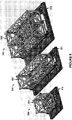
- Figure 9 illustrates example satellite deployment systems 900-901.
- View 900 includes several payloads stowed in associated deployment systems/mechanisms, while view 901 includes the payloads immediately after deployment by associated deployment systems/mechanisms.
- Figure 9 includes at least two sizes of CubeSats, namely a 1U size 910 and a 3U size 911.
- a central chassis is employed to structurally support each deployment system and couple the individual deployment systems to a common baseplate 920.
- One example deployment system 930 is shown for clarity in Figure 9 .
- This combined structure/mechanism can be integrated into an upper stage of a launch system, such as a rocket vehicle. Multiple deployment mechanisms can thus be employed to carry and deploy several payloads, with one deployment mechanism included for each payload/satellite.
- Figure 9 also illustrates optional arms 920-921 which are associated with payloads 910-911.
- Arms 920-921 can be employed to depress microswitches in each payload, such as the microswitches typically included in rail ends of CubeSats. These microswitches can be used to indicate successful deployment of the payload.
- the enhanced deployment mechanisms discussed herein do not require use of arms 920-921. Weight and cost can be reduced by eliminating arms in certain applications.
- the payloads can be mounted so that associated protrusions/rails are oriented with microswitches inserted into the deployment mechanism hook features or roller features.
Landscapes
- Engineering & Computer Science (AREA)
- Remote Sensing (AREA)
- Aviation & Aerospace Engineering (AREA)
- Physics & Mathematics (AREA)
- Astronomy & Astrophysics (AREA)
- General Physics & Mathematics (AREA)
- Details Of Aerials (AREA)
- Micromachines (AREA)
- Connection Of Plates (AREA)
Claims (10)
- Satelliteneinsatzvorrichtung (102), umfassend:eine Grundplatte (120);gegenüberliegende Halteelemente (122), die konfiguriert sind, um Vorsprünge (111) eines Satelliten (110) in Eingriff zu nehmen und den Satelliten (110) in Bezug auf die Grundplatte (120) zu halten;zumindest ein Schubelement (127), das konfiguriert ist, um eine Einsatzkraft auf den Satelliten (110) gegen die gegenüberliegenden Halteelemente (122) vorzuspannen, wenn die Vorsprünge (111) des Satelliten (110) in den gegenüberliegenden Halteelementen (122) festgehalten werden;ein Aktuatorsystem (140); undeinen Einsatzmechanismus (130), der konfiguriert ist, um die gegenüberliegenden Halteelemente (122) als Reaktion auf das Auslösen durch das Aktuatorsystem (140) zu spreizen und die Vorsprünge (111) des Satelliten (110) zum Einsatz des Satelliten (110) weg von der Grundplatte (120) unter Verwendung von zumindest der Einsatzkraft freizugeben;dadurch gekennzeichnet, dass der Einsatzmechanismus (130) Folgendes umfasst:einen Hammerarm (124), der an ein Hammerelement (125) gekoppelt ist, wobei das Hammerelement (125) in einer verriegelten Position durch eine Zugfeder (132) gegen ein Abzugselement (126) gehalten wird;wobei sowohl das Hammerelement (125) als auch das Abzugselement (126) schwenkbar an die Grundplatte (120) gekoppelt sind; wobei das Abzugselement (126) an das Aktuatorsystem (140) gekoppelt ist, wobei das Abzugselement (126) konfiguriert ist, um das Hammerelement (125) und den Hammerarm (124) freizugeben, wenn es durch das Aktuatorsystem ausgelöst wird, was zu Drehung der kombinierten Struktur aus Hammerelement (125) und Hammerarm (124) führt; undBetätigungsstangen (123), die jeweils an den Hammerarm (124) und die gegenüberliegenden Halteelemente (122) gekoppelt sind,wobei die Betätigungsstangen (123) konfiguriert sind, um die gegenüberliegenden Halteelemente (122) als Reaktion auf die Bewegung des Hammerarms (124) zu bewegen.
- Satelliteneinsatzvorrichtung (102) nach Anspruch 1, wobei die gegenüberliegenden Halteelemente (122) Rollenabschnitte (651) umfassen, die konfiguriert sind, um an die Vorsprünge (111) des Satelliten (110) zu koppeln, und konfiguriert sind, um Rollen der gegenüberliegenden Halteelemente (122) in Bezug auf die Vorsprünge (111) zu ermöglichen, wenn die gegenüberliegenden Halteelemente (122) gespreizt sind.
- Satelliteneinsatzvorrichtung (102) nach Anspruch 1, wobei die gegenüberliegenden Halteelemente (122) auf linearen Schienen (133) montiert sind, die an die Grundplatte (120) gekoppelt sind, und die gegenüberliegenden Halteelemente (122) konfiguriert sind, um entlang der linearen Schienen (133) zu gleiten.
- Satelliteneinsatzvorrichtung (102) nach Anspruch 1, wobei die gegenüberliegenden Halteelemente (122) konfiguriert sind, um Bewegung des Satelliten (110) in zumindest zwei Dimensionen einzuschränken, wenn die Vorsprünge (111) des Satelliten (110) durch die gegenüberliegenden Halteelemente (122) in Eingriff genommen sind.
- Satelliteneinsatzvorrichtung (102) nach Anspruch 1, wobei das zumindest eine Schubelement (127) ein Druckfedersystem umfasst, das konfiguriert ist, um zusammengedrückt zu werden, wenn der Satellit (110) in die gegenüberliegenden Halteelemente (122) in Eingriff genommen ist, um die Einsatzkraft aufzubauen.
- Satelliteneinsatzvorrichtung (102) nach Anspruch 1, wobei das Hammerelement (125) und das Abzugselement (126) durch zugeordnete Lagermerkmale jeweils schwenkbar an die Grundplatte (120) gekoppelt sind.
- Satelliteneinsatzvorrichtung (102) nach Anspruch 1, wobei das Aktuatorsystem (140) einen Linearaktuator umfasst, der zumindest eines von einem Leitspindelaktuator, Kugelumlaufspindelaktuator, Linearmotoraktuator, Paraffinaktuator und Solenoidaktuator umfasst.
- Satelliteneinsatzvorrichtung (102) nach Anspruch 1, die konfiguriert ist, um einen CubeSat-Formfaktor-Satelliten in Eingriff zu nehmen, und wobei die gegenüberliegenden Halteelemente (122) konfiguriert sind, um Schienenvorsprünge des CubeSat in Eingriff zu nehmen.
- Satelliteneinsatzvorrichtung (102) nach Anspruch 8, wobei zumindest eines der gegenüberliegenden Halteelemente (122) konfiguriert ist, um zumindest einen Druckschalter zu drücken, der an zumindest einem Ende der Schienen des Satelliten (110) bereitgestellt ist, wenn der Satellit (110) in den gegenüberliegenden Halteelementen (122) festgehalten wird.
- Verfahren zum Betreiben eines Satelliteneinsatzmechanismus (102), wobei das Verfahren Folgendes umfasst:Eingreifen in Vorsprünge (111) eines Satelliten (110) unter Verwendung von zumindest gegenüberliegenden Halteelementen (122), welche die Vorsprünge (111) des Satelliten (110) festhalten, wenn die gegenüberliegenden Halteelemente (122) in einer geschlossenen relativen Position sind; wobei der Einsatzmechanismus (102) einen Hammerarm (124) umfasst, der an ein Hammerelement (125) gekoppelt ist, wobei das Hammerelement (125) konfiguriert ist, um in einer verriegelten Position durch eine Zugfeder (132) gegen ein Abzugselement (126) gehalten zu werden, wobei sowohl das Hammerelement (125) als auch das Abzugselement (126) schwenkbar an eine Grundplatte (120) gekoppelt sind, und wobei Betätigungsstangen (123) jeweils an den Hammerarm (124) und die gegenüberliegenden Halteelemente (122) gekoppelt sind;Verriegeln der gegenüberliegenden Halteelemente (122) in die geschlossene relative Position unter Verwendung des Abzugselements (126);wobei als Reaktion auf Drehung des Abzugselements (126) durch ein Betätigungssystem (140) bis zu einem Schwellenwert, die die Drehung der kombinierten Struktur aus Hammerelement (125) und Hammerarm (124) auslöst, die Betätigungsstangen (123) die gegenüberliegenden Halteelemente (122) in eine offene relative Position spreizen und die Vorsprünge (111) des Satelliten (110) freigeben; undEinsetzen des Satelliten (110) unter Verwendung von zumindest einer Einsatzkraft, die auf dem Satelliten (110) während des Einführens des Satelliten (110) in den Satelliteneinsatzmechanismus (102) aufgebaut wird.
Applications Claiming Priority (2)
| Application Number | Priority Date | Filing Date | Title |
|---|---|---|---|
| US15/383,968 US10538348B2 (en) | 2016-12-19 | 2016-12-19 | Triggered satellite deployment mechanism |
| PCT/US2016/068027 WO2018118042A1 (en) | 2016-12-19 | 2016-12-21 | Triggered satellite deployment mechanism |
Publications (3)
| Publication Number | Publication Date |
|---|---|
| EP3554950A1 EP3554950A1 (de) | 2019-10-23 |
| EP3554950A4 EP3554950A4 (de) | 2021-01-06 |
| EP3554950B1 true EP3554950B1 (de) | 2022-09-14 |
Family
ID=62557304
Family Applications (1)
| Application Number | Title | Priority Date | Filing Date |
|---|---|---|---|
| EP16924261.7A Active EP3554950B1 (de) | 2016-12-19 | 2016-12-21 | Mechanismus zum einsatz eines ausgelösten satelliten |
Country Status (4)
| Country | Link |
|---|---|
| US (1) | US10538348B2 (de) |
| EP (1) | EP3554950B1 (de) |
| JP (1) | JP2020514155A (de) |
| WO (1) | WO2018118042A1 (de) |
Families Citing this family (23)
| Publication number | Priority date | Publication date | Assignee | Title |
|---|---|---|---|---|
| US11254453B2 (en) | 2016-11-14 | 2022-02-22 | Space Systems/Loral, Llc | Smallsat payload configuration |
| US20200198812A1 (en) * | 2017-07-28 | 2020-06-25 | Ruag Space Ab | A multiple payload set and method for assembly |
| AU2018375992B2 (en) * | 2017-12-01 | 2024-06-13 | D-ORBIT S.p.A. | Method of releasing artificial satellites in earth's orbit |
| FR3076817B1 (fr) * | 2018-01-16 | 2020-02-14 | Arianegroup Sas | Procede d'ejection d'une charge utile depuis un vehicule spatial anime d'une force de propulsion continue |
| WO2019223984A1 (en) * | 2018-05-24 | 2019-11-28 | The European Union, Represented By The European Commission | Efficient satellite structure concept for single or stacking multiple launches |
| WO2020065660A1 (en) * | 2018-09-24 | 2020-04-02 | Indian Space Research Organisation | A system and method for launching multiple satellites from a launch vehicle |
| CN109178343B (zh) * | 2018-09-28 | 2020-03-31 | 燕山大学 | 一种助展助缩式折展机构 |
| CN109229433B (zh) * | 2018-10-29 | 2020-04-28 | 浙江大学 | 一种皮卫星星箭固定及分离装置 |
| CN109484681B (zh) * | 2018-10-29 | 2020-09-18 | 北京卫星制造厂有限公司 | 一种自恢复触发机构 |
| US11377235B2 (en) * | 2019-04-26 | 2022-07-05 | L2 Solutions, Llc | Method and apparatus for satellite deployment |
| US11787572B1 (en) | 2019-05-14 | 2023-10-17 | Space Exploration Technologies Corp. | Spacecraft stack assembly configured for stacking, securing, and releasing spacecraft |
| US11878820B1 (en) | 2019-05-14 | 2024-01-23 | Space Exploration Technologies Corp. | Method for stacking, securing, and releasing a spacecraft stack assembly from a rocket |
| CN110228608A (zh) * | 2019-05-24 | 2019-09-13 | 上海宇航系统工程研究所 | 一种适应于侧挂式卫星的点式连接分离装置 |
| US11565834B2 (en) * | 2019-11-08 | 2023-01-31 | The Boeing Company | Clockable secondary payload bridges for a payload adapter |
| EP3854699B1 (de) * | 2020-01-21 | 2025-06-18 | Space Systems/Loral, LLC | Nutzlastkonfiguration eines kleinsatelliten |
| US11958638B1 (en) | 2020-05-14 | 2024-04-16 | Space Exploration Technologies Corp. | Spacecraft solar array biasing and tensioning system |
| IT202000012415A1 (it) | 2020-05-26 | 2021-11-26 | Thales Alenia Space Italia Spa Con Unico Socio | Sistema di rilascio di satelliti da un lanciatore |
| US12017808B2 (en) * | 2021-12-17 | 2024-06-25 | Maxar Space Llc | Dispenserless multi-satellite launch configuration with simple adapter interface |
| US12227315B2 (en) | 2022-10-17 | 2025-02-18 | Maxar Space Llc | Shockless spacecraft dispenser |
| US12221235B2 (en) * | 2022-10-20 | 2025-02-11 | Sidus Space, Inc. | Cube satellite space deployer system and method |
| US20240239522A1 (en) * | 2023-01-12 | 2024-07-18 | Spaceflight Inc. | Systems and apparatus for a configurable annex base (cab) on an orbital transfer vehicle (otv) for payload rideshare missions |
| US12214909B1 (en) | 2023-07-17 | 2025-02-04 | Maxar Space Llc | Dispensing hinge assembly |
| US12600497B2 (en) | 2023-07-17 | 2026-04-14 | Maxar Space Llc | Linked spacecraft dispensing |
Family Cites Families (18)
| Publication number | Priority date | Publication date | Assignee | Title |
|---|---|---|---|---|
| US4300737A (en) | 1978-05-30 | 1981-11-17 | Hughes Aircraft Company | Satellite deployment system with remotely controlled relocking capability |
| EP0314469B1 (de) | 1987-10-27 | 1993-06-23 | Fujitsu Limited | Verfahren und Vorrichtung zur Herstellung von Biopolymer-Einkristall |
| JPH01157100U (de) * | 1988-04-21 | 1989-10-30 | ||
| US5040748A (en) * | 1990-02-20 | 1991-08-20 | General Dynamics Corporation/Space Systems Division | Payload adapter ring |
| US6126115A (en) * | 1997-01-21 | 2000-10-03 | Lockheed Martin Corporation | Apparatus for retaining and releasing a payload |
| JP2000177699A (ja) * | 1998-12-21 | 2000-06-27 | Mitsubishi Electric Corp | 衛星搭載用保持解放装置 |
| US7908973B2 (en) | 2004-11-05 | 2011-03-22 | Raytheon Company | Lightweight deployment system and method |
| JP5569150B2 (ja) * | 2010-05-31 | 2014-08-13 | 株式会社Ihi | 人工衛星搭載システム |
| JP5677818B2 (ja) * | 2010-11-24 | 2015-02-25 | パナソニック デバイスSunx竜野株式会社 | 制御機器 |
| US8939409B2 (en) | 2012-05-07 | 2015-01-27 | The Johns Hopkins University | Adaptor system for deploying small satellites |
| US9415883B2 (en) * | 2013-04-25 | 2016-08-16 | Planetary Systems Corporation | Canisterized satellite dispenser |
| CN103662103B (zh) * | 2013-11-20 | 2015-09-30 | 上海宇航系统工程研究所 | 一种可更换模块拉紧释放装置 |
| JP6581601B2 (ja) * | 2014-05-19 | 2019-09-25 | マクドナルド デットワイラー アンド アソシエイツ インコーポレーテッド | ペイロード射出システム |
| US9845166B2 (en) | 2014-06-04 | 2017-12-19 | Ventions, Llc | Pneumatic cubesat payload deployment system utilizing launch vehicle tank pressure |
| US9567109B2 (en) * | 2014-09-17 | 2017-02-14 | The Boeing Company | Space structure deployment system |
| US10053243B2 (en) * | 2015-04-22 | 2018-08-21 | The Johns Hopkins University | Release system for deploying satellites |
| US9796488B2 (en) * | 2015-10-02 | 2017-10-24 | The Boeing Company | Dual port payload attach ring compatible satellite |
| US9731822B1 (en) * | 2016-03-30 | 2017-08-15 | The Boeing Company | Modular testable release mechanism |
-
2016
- 2016-12-19 US US15/383,968 patent/US10538348B2/en active Active
- 2016-12-21 JP JP2019533062A patent/JP2020514155A/ja active Pending
- 2016-12-21 EP EP16924261.7A patent/EP3554950B1/de active Active
- 2016-12-21 WO PCT/US2016/068027 patent/WO2018118042A1/en not_active Ceased
Also Published As
| Publication number | Publication date |
|---|---|
| EP3554950A4 (de) | 2021-01-06 |
| EP3554950A1 (de) | 2019-10-23 |
| NZ754914A (en) | 2020-12-18 |
| US20180170586A1 (en) | 2018-06-21 |
| JP2020514155A (ja) | 2020-05-21 |
| US10538348B2 (en) | 2020-01-21 |
| WO2018118042A1 (en) | 2018-06-28 |
Similar Documents
| Publication | Publication Date | Title |
|---|---|---|
| EP3554950B1 (de) | Mechanismus zum einsatz eines ausgelösten satelliten | |
| JP6581601B2 (ja) | ペイロード射出システム | |
| US6119984A (en) | Low shock anti-friction release device | |
| US5040749A (en) | Spacecraft berthing mechanism with discrete impact attennation means | |
| US20020102130A1 (en) | Connector assembly | |
| US6311930B1 (en) | Anti-friction release device | |
| Peffer et al. | Development and transition of low-shock spacecraft release devices for small satellites | |
| CN110914157B (zh) | 用于捕获客户飞行器的系统和相关方法 | |
| JP7713957B2 (ja) | ビークル捕獲組立体ならびに関連するデバイス、システム、および方法 | |
| EP4299451B1 (de) | Halte- und lösevorrichtung und anordnung für raumschiffe | |
| WO2010027780A1 (en) | Rotary actuator ball-detent locking mechanism | |
| US6547476B2 (en) | Universal spacecraft separation node | |
| Grimm et al. | The MASCOT separation mechanism: CD Grimm et al. | |
| US4860974A (en) | Payload deployment method and system | |
| JPH05112300A (ja) | 宇宙飛行体からの有用負荷の放出装置 | |
| Dowen et al. | Development of a reusable, low-shock clamp band separation system for small spacecraft release applications | |
| NZ754914B2 (en) | Triggered satellite deployment mechanism | |
| Peffer et al. | On-orbit experiments and applications of shape memory alloy mechanisms | |
| Nava et al. | REACT: resettable hold down and release actuator for space applications | |
| US5647561A (en) | Containment assembly for spin table | |
| WO2023059288A2 (en) | Rocket, missile and satellite components spring release system | |
| EP3475166B1 (de) | Beförderungssystem | |
| Fosness et al. | Overview of spacecraft deployment and release devices efforts at the Air Force Research Laboratory | |
| US12214909B1 (en) | Dispensing hinge assembly | |
| Cebrian et al. | RUAG’s approach to develop a modular low shock separation and jettison system |
Legal Events
| Date | Code | Title | Description |
|---|---|---|---|
| STAA | Information on the status of an ep patent application or granted ep patent |
Free format text: STATUS: THE INTERNATIONAL PUBLICATION HAS BEEN MADE |
|
| PUAI | Public reference made under article 153(3) epc to a published international application that has entered the european phase |
Free format text: ORIGINAL CODE: 0009012 |
|
| STAA | Information on the status of an ep patent application or granted ep patent |
Free format text: STATUS: REQUEST FOR EXAMINATION WAS MADE |
|
| 17P | Request for examination filed |
Effective date: 20190613 |
|
| AK | Designated contracting states |
Kind code of ref document: A1 Designated state(s): AL AT BE BG CH CY CZ DE DK EE ES FI FR GB GR HR HU IE IS IT LI LT LU LV MC MK MT NL NO PL PT RO RS SE SI SK SM TR |
|
| AX | Request for extension of the european patent |
Extension state: BA ME |
|
| DAV | Request for validation of the european patent (deleted) | ||
| DAX | Request for extension of the european patent (deleted) | ||
| A4 | Supplementary search report drawn up and despatched |
Effective date: 20201203 |
|
| RIC1 | Information provided on ipc code assigned before grant |
Ipc: B64G 1/22 20060101ALI20201127BHEP Ipc: B64G 1/64 20060101ALI20201127BHEP Ipc: B64G 1/10 20060101AFI20201127BHEP Ipc: B64G 1/24 20060101ALI20201127BHEP Ipc: H01Q 1/12 20060101ALI20201127BHEP Ipc: H01Q 1/00 20060101ALI20201127BHEP |
|
| GRAP | Despatch of communication of intention to grant a patent |
Free format text: ORIGINAL CODE: EPIDOSNIGR1 |
|
| STAA | Information on the status of an ep patent application or granted ep patent |
Free format text: STATUS: GRANT OF PATENT IS INTENDED |
|
| INTG | Intention to grant announced |
Effective date: 20220413 |
|
| GRAS | Grant fee paid |
Free format text: ORIGINAL CODE: EPIDOSNIGR3 |
|
| GRAL | Information related to payment of fee for publishing/printing deleted |
Free format text: ORIGINAL CODE: EPIDOSDIGR3 |
|
| GRAS | Grant fee paid |
Free format text: ORIGINAL CODE: EPIDOSNIGR3 |
|
| GRAA | (expected) grant |
Free format text: ORIGINAL CODE: 0009210 |
|
| STAA | Information on the status of an ep patent application or granted ep patent |
Free format text: STATUS: THE PATENT HAS BEEN GRANTED |
|
| AK | Designated contracting states |
Kind code of ref document: B1 Designated state(s): AL AT BE BG CH CY CZ DE DK EE ES FI FR GB GR HR HU IE IS IT LI LT LU LV MC MK MT NL NO PL PT RO RS SE SI SK SM TR |
|
| REG | Reference to a national code |
Ref country code: GB Ref legal event code: FG4D |
|
| REG | Reference to a national code |
Ref country code: CH Ref legal event code: EP |
|
| REG | Reference to a national code |
Ref country code: DE Ref legal event code: R096 Ref document number: 602016075087 Country of ref document: DE |
|
| REG | Reference to a national code |
Ref country code: IE Ref legal event code: FG4D |
|
| REG | Reference to a national code |
Ref country code: AT Ref legal event code: REF Ref document number: 1518566 Country of ref document: AT Kind code of ref document: T Effective date: 20221015 |
|
| REG | Reference to a national code |
Ref country code: LT Ref legal event code: MG9D |
|
| REG | Reference to a national code |
Ref country code: NL Ref legal event code: MP Effective date: 20220914 |
|
| PG25 | Lapsed in a contracting state [announced via postgrant information from national office to epo] |
Ref country code: SE Free format text: LAPSE BECAUSE OF FAILURE TO SUBMIT A TRANSLATION OF THE DESCRIPTION OR TO PAY THE FEE WITHIN THE PRESCRIBED TIME-LIMIT Effective date: 20220914 Ref country code: RS Free format text: LAPSE BECAUSE OF FAILURE TO SUBMIT A TRANSLATION OF THE DESCRIPTION OR TO PAY THE FEE WITHIN THE PRESCRIBED TIME-LIMIT Effective date: 20220914 Ref country code: NO Free format text: LAPSE BECAUSE OF FAILURE TO SUBMIT A TRANSLATION OF THE DESCRIPTION OR TO PAY THE FEE WITHIN THE PRESCRIBED TIME-LIMIT Effective date: 20221214 Ref country code: LV Free format text: LAPSE BECAUSE OF FAILURE TO SUBMIT A TRANSLATION OF THE DESCRIPTION OR TO PAY THE FEE WITHIN THE PRESCRIBED TIME-LIMIT Effective date: 20220914 Ref country code: LT Free format text: LAPSE BECAUSE OF FAILURE TO SUBMIT A TRANSLATION OF THE DESCRIPTION OR TO PAY THE FEE WITHIN THE PRESCRIBED TIME-LIMIT Effective date: 20220914 Ref country code: FI Free format text: LAPSE BECAUSE OF FAILURE TO SUBMIT A TRANSLATION OF THE DESCRIPTION OR TO PAY THE FEE WITHIN THE PRESCRIBED TIME-LIMIT Effective date: 20220914 |
|
| REG | Reference to a national code |
Ref country code: AT Ref legal event code: MK05 Ref document number: 1518566 Country of ref document: AT Kind code of ref document: T Effective date: 20220914 |
|
| PG25 | Lapsed in a contracting state [announced via postgrant information from national office to epo] |
Ref country code: HR Free format text: LAPSE BECAUSE OF FAILURE TO SUBMIT A TRANSLATION OF THE DESCRIPTION OR TO PAY THE FEE WITHIN THE PRESCRIBED TIME-LIMIT Effective date: 20220914 Ref country code: GR Free format text: LAPSE BECAUSE OF FAILURE TO SUBMIT A TRANSLATION OF THE DESCRIPTION OR TO PAY THE FEE WITHIN THE PRESCRIBED TIME-LIMIT Effective date: 20221215 |
|
| PG25 | Lapsed in a contracting state [announced via postgrant information from national office to epo] |
Ref country code: SM Free format text: LAPSE BECAUSE OF FAILURE TO SUBMIT A TRANSLATION OF THE DESCRIPTION OR TO PAY THE FEE WITHIN THE PRESCRIBED TIME-LIMIT Effective date: 20220914 Ref country code: RO Free format text: LAPSE BECAUSE OF FAILURE TO SUBMIT A TRANSLATION OF THE DESCRIPTION OR TO PAY THE FEE WITHIN THE PRESCRIBED TIME-LIMIT Effective date: 20220914 Ref country code: PT Free format text: LAPSE BECAUSE OF FAILURE TO SUBMIT A TRANSLATION OF THE DESCRIPTION OR TO PAY THE FEE WITHIN THE PRESCRIBED TIME-LIMIT Effective date: 20230116 Ref country code: ES Free format text: LAPSE BECAUSE OF FAILURE TO SUBMIT A TRANSLATION OF THE DESCRIPTION OR TO PAY THE FEE WITHIN THE PRESCRIBED TIME-LIMIT Effective date: 20220914 Ref country code: CZ Free format text: LAPSE BECAUSE OF FAILURE TO SUBMIT A TRANSLATION OF THE DESCRIPTION OR TO PAY THE FEE WITHIN THE PRESCRIBED TIME-LIMIT Effective date: 20220914 Ref country code: AT Free format text: LAPSE BECAUSE OF FAILURE TO SUBMIT A TRANSLATION OF THE DESCRIPTION OR TO PAY THE FEE WITHIN THE PRESCRIBED TIME-LIMIT Effective date: 20220914 |
|
| PG25 | Lapsed in a contracting state [announced via postgrant information from national office to epo] |
Ref country code: SK Free format text: LAPSE BECAUSE OF FAILURE TO SUBMIT A TRANSLATION OF THE DESCRIPTION OR TO PAY THE FEE WITHIN THE PRESCRIBED TIME-LIMIT Effective date: 20220914 Ref country code: PL Free format text: LAPSE BECAUSE OF FAILURE TO SUBMIT A TRANSLATION OF THE DESCRIPTION OR TO PAY THE FEE WITHIN THE PRESCRIBED TIME-LIMIT Effective date: 20220914 Ref country code: IS Free format text: LAPSE BECAUSE OF FAILURE TO SUBMIT A TRANSLATION OF THE DESCRIPTION OR TO PAY THE FEE WITHIN THE PRESCRIBED TIME-LIMIT Effective date: 20230114 Ref country code: EE Free format text: LAPSE BECAUSE OF FAILURE TO SUBMIT A TRANSLATION OF THE DESCRIPTION OR TO PAY THE FEE WITHIN THE PRESCRIBED TIME-LIMIT Effective date: 20220914 |
|
| REG | Reference to a national code |
Ref country code: DE Ref legal event code: R097 Ref document number: 602016075087 Country of ref document: DE |
|
| PG25 | Lapsed in a contracting state [announced via postgrant information from national office to epo] |
Ref country code: NL Free format text: LAPSE BECAUSE OF FAILURE TO SUBMIT A TRANSLATION OF THE DESCRIPTION OR TO PAY THE FEE WITHIN THE PRESCRIBED TIME-LIMIT Effective date: 20220914 Ref country code: AL Free format text: LAPSE BECAUSE OF FAILURE TO SUBMIT A TRANSLATION OF THE DESCRIPTION OR TO PAY THE FEE WITHIN THE PRESCRIBED TIME-LIMIT Effective date: 20220914 |
|
| PLBE | No opposition filed within time limit |
Free format text: ORIGINAL CODE: 0009261 |
|
| STAA | Information on the status of an ep patent application or granted ep patent |
Free format text: STATUS: NO OPPOSITION FILED WITHIN TIME LIMIT |
|
| PG25 | Lapsed in a contracting state [announced via postgrant information from national office to epo] |
Ref country code: DK Free format text: LAPSE BECAUSE OF FAILURE TO SUBMIT A TRANSLATION OF THE DESCRIPTION OR TO PAY THE FEE WITHIN THE PRESCRIBED TIME-LIMIT Effective date: 20220914 |
|
| 26N | No opposition filed |
Effective date: 20230615 |
|
| PG25 | Lapsed in a contracting state [announced via postgrant information from national office to epo] |
Ref country code: SI Free format text: LAPSE BECAUSE OF FAILURE TO SUBMIT A TRANSLATION OF THE DESCRIPTION OR TO PAY THE FEE WITHIN THE PRESCRIBED TIME-LIMIT Effective date: 20220914 |
|
| PGFP | Annual fee paid to national office [announced via postgrant information from national office to epo] |
Ref country code: GB Payment date: 20231213 Year of fee payment: 8 |
|
| PGFP | Annual fee paid to national office [announced via postgrant information from national office to epo] |
Ref country code: MC Payment date: 20231221 Year of fee payment: 8 |
|
| PGFP | Annual fee paid to national office [announced via postgrant information from national office to epo] |
Ref country code: LU Payment date: 20231227 Year of fee payment: 8 Ref country code: IE Payment date: 20231227 Year of fee payment: 8 Ref country code: FR Payment date: 20231227 Year of fee payment: 8 |
|
| PGFP | Annual fee paid to national office [announced via postgrant information from national office to epo] |
Ref country code: BE Payment date: 20231227 Year of fee payment: 8 |
|
| PG25 | Lapsed in a contracting state [announced via postgrant information from national office to epo] |
Ref country code: HU Free format text: LAPSE BECAUSE OF FAILURE TO SUBMIT A TRANSLATION OF THE DESCRIPTION OR TO PAY THE FEE WITHIN THE PRESCRIBED TIME-LIMIT; INVALID AB INITIO Effective date: 20161221 |
|
| PG25 | Lapsed in a contracting state [announced via postgrant information from national office to epo] |
Ref country code: CY Free format text: LAPSE BECAUSE OF FAILURE TO SUBMIT A TRANSLATION OF THE DESCRIPTION OR TO PAY THE FEE WITHIN THE PRESCRIBED TIME-LIMIT Effective date: 20220914 |
|
| PGFP | Annual fee paid to national office [announced via postgrant information from national office to epo] |
Ref country code: DE Payment date: 20231229 Year of fee payment: 8 Ref country code: CH Payment date: 20240101 Year of fee payment: 8 |
|
| PG25 | Lapsed in a contracting state [announced via postgrant information from national office to epo] |
Ref country code: MK Free format text: LAPSE BECAUSE OF FAILURE TO SUBMIT A TRANSLATION OF THE DESCRIPTION OR TO PAY THE FEE WITHIN THE PRESCRIBED TIME-LIMIT Effective date: 20220914 Ref country code: IT Free format text: LAPSE BECAUSE OF FAILURE TO SUBMIT A TRANSLATION OF THE DESCRIPTION OR TO PAY THE FEE WITHIN THE PRESCRIBED TIME-LIMIT Effective date: 20220914 |
|
| PG25 | Lapsed in a contracting state [announced via postgrant information from national office to epo] |
Ref country code: TR Free format text: LAPSE BECAUSE OF FAILURE TO SUBMIT A TRANSLATION OF THE DESCRIPTION OR TO PAY THE FEE WITHIN THE PRESCRIBED TIME-LIMIT Effective date: 20220914 |
|
| PG25 | Lapsed in a contracting state [announced via postgrant information from national office to epo] |
Ref country code: BG Free format text: LAPSE BECAUSE OF FAILURE TO SUBMIT A TRANSLATION OF THE DESCRIPTION OR TO PAY THE FEE WITHIN THE PRESCRIBED TIME-LIMIT Effective date: 20220914 |
|
| PG25 | Lapsed in a contracting state [announced via postgrant information from national office to epo] |
Ref country code: MT Free format text: LAPSE BECAUSE OF FAILURE TO SUBMIT A TRANSLATION OF THE DESCRIPTION OR TO PAY THE FEE WITHIN THE PRESCRIBED TIME-LIMIT Effective date: 20220914 |
|
| REG | Reference to a national code |
Ref country code: DE Ref legal event code: R119 Ref document number: 602016075087 Country of ref document: DE |
|
| PG25 | Lapsed in a contracting state [announced via postgrant information from national office to epo] |
Ref country code: MC Free format text: LAPSE BECAUSE OF NON-PAYMENT OF DUE FEES Effective date: 20241231 |
|
| REG | Reference to a national code |
Ref country code: CH Ref legal event code: PL |
|
| PG25 | Lapsed in a contracting state [announced via postgrant information from national office to epo] |
Ref country code: LU Free format text: LAPSE BECAUSE OF NON-PAYMENT OF DUE FEES Effective date: 20241221 |
|
| GBPC | Gb: european patent ceased through non-payment of renewal fee |
Effective date: 20241221 |
|
| REG | Reference to a national code |
Ref country code: BE Ref legal event code: MM Effective date: 20241231 |
|
| PG25 | Lapsed in a contracting state [announced via postgrant information from national office to epo] |
Ref country code: DE Free format text: LAPSE BECAUSE OF NON-PAYMENT OF DUE FEES Effective date: 20250701 |
|
| PG25 | Lapsed in a contracting state [announced via postgrant information from national office to epo] |
Ref country code: GB Free format text: LAPSE BECAUSE OF NON-PAYMENT OF DUE FEES Effective date: 20241221 Ref country code: BE Free format text: LAPSE BECAUSE OF NON-PAYMENT OF DUE FEES Effective date: 20241231 |
|
| PG25 | Lapsed in a contracting state [announced via postgrant information from national office to epo] |
Ref country code: FR Free format text: LAPSE BECAUSE OF NON-PAYMENT OF DUE FEES Effective date: 20241231 |
|
| PG25 | Lapsed in a contracting state [announced via postgrant information from national office to epo] |
Ref country code: CH Free format text: LAPSE BECAUSE OF NON-PAYMENT OF DUE FEES Effective date: 20241231 |
|
| PG25 | Lapsed in a contracting state [announced via postgrant information from national office to epo] |
Ref country code: IE Free format text: LAPSE BECAUSE OF NON-PAYMENT OF DUE FEES Effective date: 20241221 |